
Oil & Gas Science and Technology – Rev. IFP
, Vol. 60 (2005), No. 3, pp. 461-474
Copyright © 2005,
Post-combustion Decarbonisation Processes
D.W. Bailey
1
and P.H.M. Feron
2
1 Alstom Power Turbo-Systems Technology Centre, Cambridge Road, Whetstone, Leicester, LE8 6LH - United Kingdom
2 TNO Science and Industry, PO Box 342, 7300 AH Apeldoorn - The Netherlands
e-mail: david@aerospace.co.uk - paul.feron@tno.nl
Résumé — Capture post-combustion — Dans le cas de la capture post-combustion, le CO
2
est séparé
des gaz effluents. Ce procédé convient à la génération d’électricité conventionnelle et aux systèmes de
conversion d’énergie. Les principaux procédés de conversion d’énergie et leurs performances sont décrits
dans cet article. La technologie utilisée aujourd’hui, qui consiste à séparer le CO
2
des effluents gazeux à
l’aide de solvants, est présentée et les principaux procédés sont discutés. Plusieurs pistes de
développement de ces procédés sont envisageables à l’avenir : accroissement de l’efficacité des procédés
actuels, nouveaux procédés d’absorption avec de meilleurs solvants, utilisation de membranes, etc.
Abstract — Post-Combustion Decarbonisation Processes — Post-combustion decarbonisation processes
are focused on the separation of CO
2
from flue gases. The process route is ideally suitable for
conventional power stations and energy conversion systems. The main energy conversion processes and
components (steam boilers, gas turbines) are described and performances are given. The state-of-the-art
process to separate CO
2
from a flue gas, using the monoethanolamine solvent is discussed and
performances of the leading processes are presented. Several development options are suggested such as
improvement of available solvents and processes, novel absorption processes and membranes.
Capture and Geological Storage: State-of-the-Art
Capture et stockage géologique du CO
D o s s i e r
Oil & Gas Science and Technology – Rev. IFP, Vol. 60 (2005), No. 3
1 BASIC PROCESS AND ENERGY CONVERSION
DESCRIPTION
The energy conversion systems for fossil fuels can broadly
be classified by the technology variants adopted to produce
power from coal and gas. An overview of coal and gas power
generation is provided along with an introduction to the
technical variants deployed.
1.1 Coal Power Generation
Coal fired boiler technology has developed rapidly over the
last century, largely driven by industrialisation. The need for
power and electricity has driven increases in the size of plant
and its availability. During the last century, this has been
achieved by increases in both steam temperature and pressure
brought about through improved materials. During this time,
power plant efficiency has increased from less than 10% at
the turn of the century, through 20-35% during the middle of
the century to above 45% for coal fired power stations at the
end of the century (Fig. 1). As early as the 1970’s, the first
super-critical boiler with a capacity of 750 MW was
established.
1.1.1 Pulverised Fuel (PF) Boilers
In a typical PF boiler, coal is ground into fine particles before
being injected (with air) through a number of burners into the
bottom of a combustion chamber. The particles are burnt in
suspension which releases heat that is transferred to water
tubes in the walls of the combustion chamber. This process
generates steam at both high pressure and temperature which
is fed into a turbine and generator set to produce electricity.
PF boilers are defined as “subcritical” if the steam is
generated at a pressure below the critical pressure of
221.2 bar. At higher pressures, there is no distinct water and
steam phase transition, and the boiler is defined as
“supercritical”. Supercritical technology offers the benefits of
higher efficiency. In 2002, the 965 MW lignite fired power
plant at Niederaussem (Fig. 2) went on stream with a net
efficiency in excess of 45% (McMullan, 2004) and steam
pressure and temperatures of 275 bar/580-600°C.
Table 1 indicates the performance and emissions improve-
ments from the upgrade to supercritical technology for the
same sized plant.
TABLE 1
Performance of Subcritical vs. Supercritical (660MWe)
(Bozzuto et al., 2001)
Units
Sub Critical PF
Super Critical PF
Efficiency
%*
40.8
43.6
CO
2
kg/MWhr 845
791
NO
x
kg/MWhr**
2.36
2.21
SO
2
kg/MWhr**
6.3
5.9
Particulates
kg/MWhr**
0.158
0.148
*
LHV Basis (net).
** Flue gas clean up to 2001 World Bank Emissions Guidelines.
The goal of improving the efficiency of PF plant is
continuing with the development of ultra supercritical boiler
technologies. The goal of collaborative European research
and technology projects such as AD700 and COST522 is to
demonstrate that it is possible to operate plant with steam at a
pressure of 375 bar and at temperatures of 700/720°C. This
level of technology should lead to efficiencies in excess of
50%.
1.1.2 Fluidised Bed Combustion (FBC)
Due to the increasing requirement for fuel flexibility
(including the utilisation of renewable fuels such as biomass)
462
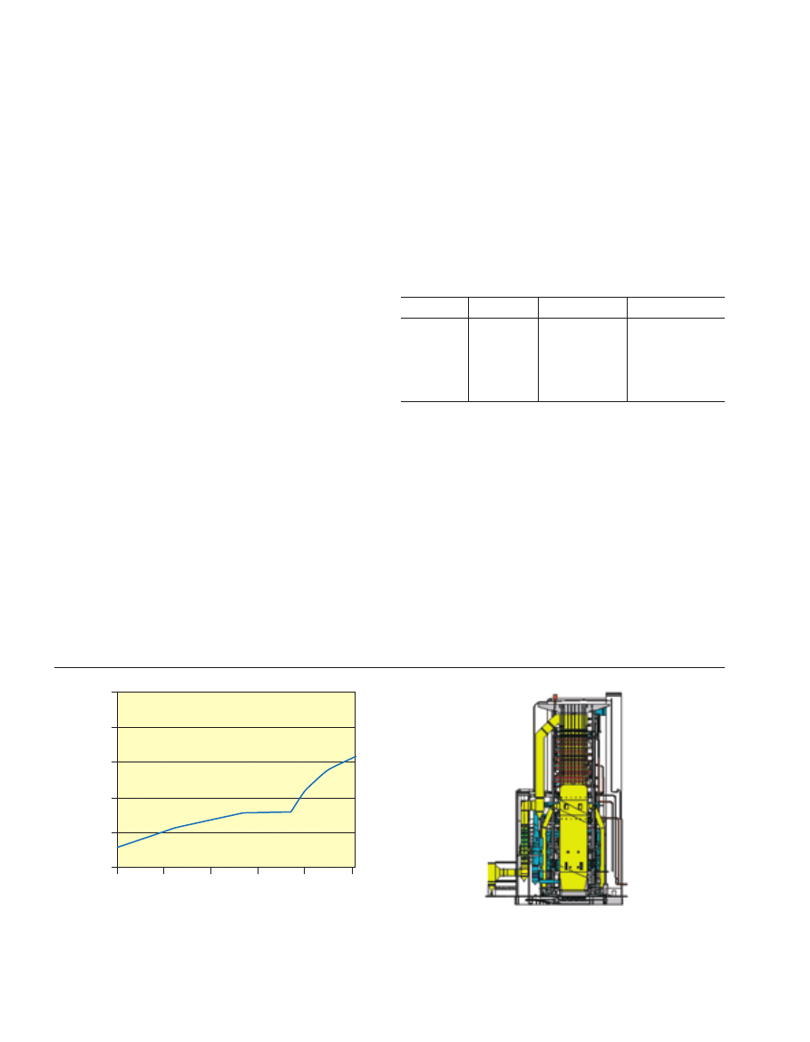
Figure 1
The efficiency of steam power plant in Europe
(Stamatelopoulos et al., 2003).
Figure 2
965 MW supercritical plant, Niederaussem, Germany (Owned
by RWE Energie, boiler supplied by Alstom et al.).
1950
30
35
40
45
50
55
1960
1970
Time
η
[%]
1980
1990
2000
Introduction of
once-through technology
175 bar/540°C/540°C
1st Supercritical plants
(240 - 280 bar
evaporated pressure)
250 bar/550°C/570°C
260 bar/580°C/600°C
280 bar/600°C/620°C
DW Bailey and PHM Feron / Post-combustion Decarbonisation Processes
there has been a requirement for technologies capable of
burning a variety of fuels efficiently and in an environ-
mentally acceptable way. These fuels are often of a poor
quality and are therefore available at low cost giving a plant
capable of burning them and an operating cost benefit that
can be substantial. Since PF technology depends on the
combustion of very finely ground particles, Fluidised Bed
Combustion (FBC) has been developed to meet these
requirements.
In an FBC plant, combustion of the fuel (which can be in
relatively large sizes of particle compared with PF plant)
takes place within a fluidised bed suspended by an ascending
air flow. The bed can be thought to behave like a fluid, with
the speed of the ascending airflow sufficient to maintain the
bed in a state of fluidisation and with a high level of mixing.
The temperature of the bed is typically 850°C which is an
optimum for low NO
x
formation and SO
x
capture by
sorbents.
There are two main types of FBC plant, Bubbling Flu-
idised Bed Combustion (BFBC) and Circulating Fluidised
Bed Combustion (CFBC) and both of these can be atmo-
spheric (BFB and CFB in Figure 3) or pressurised (PBFB
and PCFB in Figure 3).
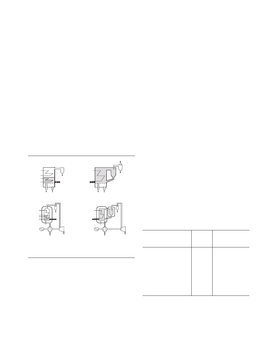
Figure 3
Illustration of the different types of fluidises bed power plants
(IFRF Combustion File 87).
The Bubbling Fluidised Bed plant maintains a dense bed
by setting the ascending airflow speed as just sufficient to
keep the bed in a state of fluidisation and high mixedness, but
also so that particles which are lifted out of the bed will still
fall back into the bed. In contrast, with the Circulating
Fluidised Bed plant, the air flow is higher through the bed
thereby entraining solid particles from the bed which are
carried upwards away from the bed surface so that the
combustion chamber is filled by a turbulent cloud of
particles. Solids leaving the combustion chamber are
collected by a cyclone and re-injected into the system thereby
reducing the amount of ash discharged with the flue gas.
The first major coal fired BFBC plant was installed in
1975 at Renfrew, Scotland. The largest BFBC power plant to
date (to re-power a 350 MW PF plant) was built in Takehara,
Japan. The trend, however, is for smaller industrial applica-
tions including co-firing of biomass and wastes with coal.
Larger scale BFBC plant (150-300 MW) tends to be supplied
for industrial application in paper and pulp mills. In contrast
with BFBC, there are more than 1,200 CFBC plants installed
with a capacity in excess of 65 GW (including 900 CFBC
plant in China with an average size of 30 MW). Plant ranges
in size from a few MW up to 300 MW. In 2002, Alstom
supplied two 250 MWe CFB Boilers (Marchetti et al., 2003)
to Choctaw Generation Limited Partnership located in
Mississippi, USA. The plant is called Red Hills (Fig. 4) and
commercial operation commenced in 2002.
Foster Wheeler has demonstrated a 297.5 MWe CFB
running on eastern bituminous fuel operating at atmospheric
pressure at Jacksonville, Duval County, Florida. Foster
Wheeler worked with Jackson Electric Authority and US
Department of Energy to develop the commercial
demonstrator which received “Power Magazine’s” 2002
Power Plant Award (Fig. 5).
Typical operating characteristics and emissions perfor-
mance is presented in Table 2 (EIS, 2000). It can be seen that
the levels of NO
x
and SO
x
emissions are substantially lower
than those obtained from PF plant. The re-circulation of the
solids in the CFB provides long particle residence times in
the combustor thereby allowing combustion to take place at a
lower temperature leading to lower NO
x
formation. The
addition of limestone to the bed enables the removal of up to
98% of the SO
2
and SO
3
from the gases.
TABLE 2
Typical Operating Characteristics of the JEA Large Scale CFB
(297.5 MWe)
JEA Large Scale CFB
Units
Combustion
DemonstrationPlant
Generating Capacity
MW
297.5
Power Production
MWh/yr
2,345,490
Efficiency (HHV)
%
34
NO
x
kg/MWh
0.429
SO
2
kg/MWh
0.715
Particulate Matter
kg/MWh
0.052
Volatile Organic Compounds
kg/MWh
0.026
Carbon Monoxide (CO)
kg/MWh
0.664
Carbon Dioxide
kg/MWh
993
The overall thermal efficiency of the CFB plant is rated at
approximately 34%. However, comparison with PF plant is
generally performed on the basis of plant with SCR (Selective
Air
Air
Air
Ash
Air
Ash
Ash
Ash
Fuel
Fuel
Fuel
Fuel
A) BF B
B) CF B
C) PBFB
D) PCFB
463
Oil & Gas Science and Technology – Rev. IFP, Vol. 60 (2005), No. 3
464
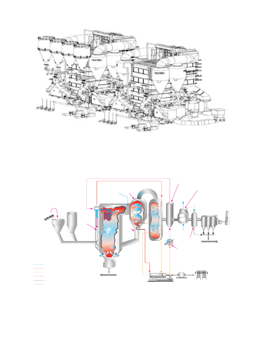
Figure 4
Red Hills – 2
×
250 MWe Circulating Fluidised Bed Boilers (Marchetti et al., 2003).
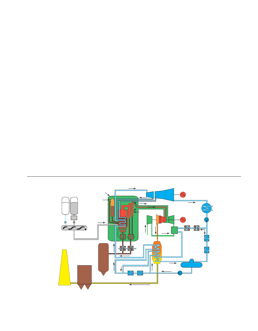
Air
Air
High pressure steam
Lower pressure steam
Water
Particulate
Lime slurry
Air
Generator
Steam turbine
Steam
Condenser
Air
Heated
air to
boiler
Air preheater
Stack
Particulate control
device
Polishing
scrubber
Economizer
Feed water
Cyclone
Intrex
Steam
Ammonia
injection
Circulating
fluidized-bed boiler
Secondary
air
Limestone
Coal/coke
Lime
slurry
Bottom
ash
To byproduct storage
To byproduct storage
Figure 5
JEA large scale CFB combustion plant (owned by JEA, developed by Foster Wheeler).
DW Bailey and PHM Feron / Post-combustion Decarbonisation Processes
465
Catalytic Reduction) and FGD (Flue Gas Desulphurisation)
technologies which reduce plant efficiency and increase
capital and O&M costs significantly.
1.1.3 Pressurised Fluidised Bed Combustion (FBC)
The pressurised FBC systems (PBFB and PCFB) involve the
combustion of the solid fuel in a fluidised bed at pressure.
Boiler tubes immersed in the fluidised bed generate steam
which is expanded through a steam turbine to drive a
generator. At the same time, the combustion gases are
expanded through a gas turbine to drive another generator
(Fig. 6). This results in higher cycle efficiency. However,
since the combustion gases are limited to about 900°C the
cycle cannot take account of the improved performance that
could be obtained from the gas turbine at higher gas inlet
temperatures.
The world’s largest PFBC (360 MW) began commercial
operations in July 2001. The plant was engineered and
constructed by Ishikawajima Harima Heavy Industries (IHI)
under licence from Alstom. IHI manufactured and erected the
pressure vessel and PFBC system internals, fuel and ash
handling equipment and the control system. Alstom supplied
the heavy-duty gas turbine (75 MWe operating at 13 bar and
850C) that creates the fluidised bed and provides air for
combustion, whilst Toshiba supplied the steam turbine
(290 MWe). The gross thermal efficiency of the plant is
reported (Yamamoto et al., 2003) to be 41.8% (net).
There are, however, several inherent problems with PFBC
technology that have limited its application:
– Particles of ash in the hot exhaust gas from the boiler
cause durability problems in the gas turbine.
– The gas turbine operates at low temperatures (850°C)
which reduces the cycle efficiency significantly.
– The availability of the PFBC plant is low due to the
complexity of the configuration and difficulty with access
to the boiler internals.
– The complex configurations are expensive and the
resulting cost of electricity is not competitive.
1.2 Gas Fired Power Plants
Gas fired power plants are very popular today both because
of reduced environmental concerns and cost. Gas fired plants
are cheaper to operate than coal fired plants despite recent
sharp rises in natural gas prices. A major reason for this is
due to the high fuel efficiency achievable with the newer
combined cycle gas power plants.
Combined cycle power plants (Fig. 7) generate electricity
using two methods; the steam cycle and gas cycle. In the
steam cycle, fuel is burned to boil water and create steam
which turns a steam turbine driving a generator to create
electricity. In the gas cycle, gas is burned in a gas turbine
which directly turns a generator to create electricity.
Combined cycle power plants operate by combining the gas
Figure 6
Schematic of a pressurised fluidised bed combustion concept (Bozzuto et al., 2001).
Solvent
Mixer
Stack
Filter
Ash silo
High pressure
preheaters
Feed water
pump
Deserator
Economiser
Ash coolers
Ash coolers
Air
Cyclones
Gas turbine
Condenser
Steam turbine
Low pressure
preheaters
Inter-
cooler
Combustor
vessel
Bed
reinjection
Coal

Oil & Gas Science and Technology – Rev. IFP, Vol. 60 (2005), No. 3
cycle and the steam cycle for higher efficiency. The hot
exhaust gases exiting the gas turbine are routed to the steam
cycle and are used to heat or boil water. These exhaust gases
typically carry away up to 70% of the energy in the fuel
before it was burned, so recovering what otherwise would be
wasted can double overall efficiency from 30% for a gas
cycle only plant to 60% using the newest combined cycle
technology.
Advancements in gas turbine technology have increased
power and efficiency while decreasing emissions and life-
cycle costs without sacrificing reliability. Retrofittable
enhancements including advanced blading design, high
temperature tolerant materials, sealing improvements, state-
of-the-art component cooling and low emission combustion
concepts have been incorporated in the newly developed gas
turbines to ensure high performance. Operating gas fired
power plants currently in use of this technology are meeting
their combined cycle efficiency, power and emissions targets
as well as the challenging and sometimes changing market
demands.
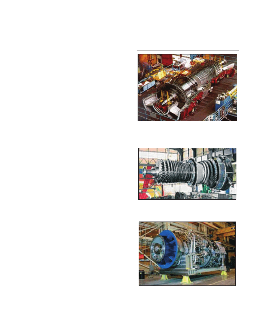
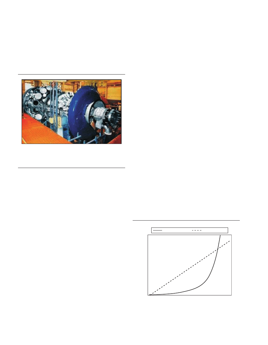
One can see the latest performance of large industrial gas
turbines developed by the major gas turbine manufacturers
(Table 3, Figs 8, 9, 10, 11). A typical power output of the
latest large industrial gas turbines is 180 MW for 60 Hz and
270 MW for 50 Hz application. The firing gas temperatures
are between 1200°C and 1400°C. The combined cycle
efficiency of the gas-fired plants is 56-58% depending on the
manufacturer. These are values of combined cycle efficiency
of the “F-class” gas turbine’s technology. “G-class” gas
turbines, which have a firing temperature of around 1500°C
and achieve a combined cycle efficiency of about 59%, have
already been developed and in operation. “H-class” gas
turbines, which apply “closed loop steam cooling” for turbine
blades, are now under development. This new concept allows
the turbine to fire at a higher temperature for increased perfor-
mance, yet without increased combustion temperatures or
466
TABLE 3
Large Industrial Gas Turbine’s performance (GT WORLD 2003-4 Spects)
Alstom General
electric
Mitsubishi Heavy
Siemens W
Industries
GT TYPE -
GT24B
GT26B
7FB
9FB
M501F
M701F
W501F
V94.3A
Frequency (Hz)
60 Hz
50 Hz
60 Hz
50 Hz
60 Hz
50 Hz
60 Hz
50 Hz
GT power (MW)
187
268.8
182
281
185
270
184
272
GT efficiency (%)
36.9
37.5
37.2
38.3
37
38.2
36.9
39.0
Combined cycle power (MW)
276.7
410.3
280.3
412.9
279
399
274
390
Combined cycle efficiency (%)
56.4
57.8
57.3
57.7
56.7
57
55.5
57.6
Pressure ratio
32
32
18.5
18.5
16
17
16
16.9
Gas firing temp (°C)
1280
1280
1371
1371
1400
1400
1350
1230
Exhaust mass flow (Kg/s)
429
623
431.8
659
453
651
457
644
Exhaust gas temperature (°C)
611
612
593
620
607
586
594
585
Stack
Air
Air
Compressor
Turbine
Hot
exhaust
gas
Combustion turbine
(Jet EngineTechnology)
How does a combined-cycle power plant work?
Heat recovery
steam generator
Steam turbine
(Traditional Steam
Technology)
Natural gas
Steam
Electric
generator
Electric
generator
Figure 7
Operation of Combined Cycle Power Plant (FPL’s new technology: the “repowered” Fort Myers plant).
DW Bailey and PHM Feron / Post-combustion Decarbonisation Processes
their resulting increased emission levels. Closed loop cooling
also minimises parasitic extraction of compressor discharged
air, thereby allowing more air to flow to the head-end of the
combustor for fuel premixing. Those turbines are expected to
achieve efficiency of 60% or more, and play a major role for
high-efficient power generation in the next decade.
There is an increasing trend toward more combined cycle
plants being commissioned in the world market for power
generation. The combined cycle efficiency is strongly
dependent on firing temperature. However the increase of the
firing temperature seems to have reached a limit with the
newly developed gas turbine engines. This saturation of the
firing temperature comes from the fact that the flame
temperature has to be kept below 1500°C to achieve low
NO
x
emission 25 ppm or less which comply within environ-
mental regulations. The combustion control to stabilise the
flame at lean fuel-to-air ratio is one of the most important
challenges for all gas turbine manufacturers.
To use costly clean energy such as natural gas effectively,
technological developments aimed at improving the effi-
ciency of the combined cycle power generation have been
vigorously promoted such as dry low NO
x
combustion, blade
cooling technology, heat resistant materials, blade design as
well as sealing improvements. The development of these key
technologies for large industrial gas turbines can be made
economical by using both the knowledge and experience
acquired during earlier aeroengine developments. Aero-
engines and their industrial derivatives, in contrast, are
optimised for maximum cycle efficiency at higher cycle
pressure ratios with lower gas turbine exit temperatures to
minimise waste heat in the exhaust. It is not possible
however in some fields to apply aeroengine’s technologies to
the industrial gas turbines due to the different sizes and
requirements. Dry low NO
x
combustors for dual fuel use in
the industrial gas turbines requires components that are much
different from those for aeroengine’s combustors. The
industrial gas turbines have some advantage over the
aeroengines with respect to the versatility of coolant, as for
instance steam or air cooled by an external cooler. This
advantage makes it possible to apply close loop steam
cooling concepts to cool turbine blades in newly developed
gas turbines. Similarly, there are other technological needs
for the industrial gas turbine manufacturers that necessitate
some deviation from technologies that may be appropriate to
aeroengine’s application.
The commercial development of combined-cycle power
plants has proceeded in parallel with gas turbine devel-
opment. Combined-cycles utilising the Brayton gas cycle and
the Rankine steam cycle with air and water as working fluids
achieve efficient, reliable, and economic power generation.
Current commercially available power generation combined-
cycle plants achieve net plant thermal efficiency typically of
some 55-59%. Further developments of gas turbine, high
temperature materials and hot gas path, metal surface cooling
technology show promise for near-term future power
generation combined-cycle plants capable of reaching 60%
or greater thermal efficiency. Fuel price escalation in the
1970s and 1980s further increased the need for more efficient
Figure 8
GT26B - 50 Hz (courtesy of Alstom Power generation).
Figure 9
Siemens V94.3A rotor.
Figure 10
GE 7FB Series - 60 Hz (courtesy of General Electric Power
Systems).
467
Oil & Gas Science and Technology – Rev. IFP, Vol. 60 (2005), No. 3
power plants for base- and mid-rage duty. This led to the
gas turbine designs in the late 1980s that were optimised
specifically for combined cycle efficiency. Where simple-
cycle efficiency is the goal a high pressure ratio is desirable,
whilst where combined-cycle efficiency is the objective more
modest pressure ratios are selected. Firing temperature has a
greater impact on combined-cycle efficiency than on simple-
cycle efficiency.
Figure 11
MHI M501G Series - 60Hz (Courtesy of Mitsubishi Heavy
Industries Ltd).
The majority of combined-cycle plants are configured
with open loop cooling of the turbine hot gas path and
cooling air supplied from the compressor. Hot gas path
components are in large part cooled by film cooling. As a
result, there is significant exhaust gas temperature drop
across the first stage nozzle, and significant “chargeable air”
required to cool down the turbine stages. The drop in exhaust
gas temperature across the first stage nozzle and the increase
in chargeable cooling loss due to the increases in turbine
firing temperature may diminish efficiency gains to the point
of being uneconomical. The concept of closed loop steam
cooling allows higher turbine firing temperature without
increasing combustion temperature. This is because gas
temperature drop across the first stage nozzle is significantly
reduced. Another important benefit is the elimination of
“chargeable cooling air” for the first and second stage
rotating and stationary airfoils. This technology is expected
to provide 2% thermal efficiency improvement. The
application of ceramic hot gas path parts and coatings show
promise for further future performance gains.
Steam cycle improvements that include increased steam
pressure and temperature with supercritical steam cycles
have near-term application. Current economic analysis
indicates, however, that the thermodynamic gain associated
with steam cycles that have steam temperatures and pressures
above the current levels cannot be justified in most cases
because of the added costs. As in the past, operating cost
(fuel price) and the cost of new technology development will
dictate the trend for increased combined-cycle efficiency.
2 STATE-OF-THE-ART
The state-of-the-art process to separate CO
2
from a flue gas is
a solvent process in which CO
2
reacts with an absorption
liquid. These chemical absorption processes are in general
applicable to gas streams at both high and low overall
process pressure, but which have a low CO
2
-partial pressure.
They make use of the reversible nature of the chemical
reaction, effected by a temperature difference. The heat of
absorption is in the range 50-80 kJ/mole CO
2
. Figure 12
shows the equilibrium CO
2
-partial pressure of a chemical
solvent and a physical solvent. The dependence between gas
partial pressure and solvent loading is not linear one. At low
partial pressure the loading of a chemical solvent will be
higher.
The regeneration in a chemical solvent process is carried
out at elevated temperatures (100-140°C) and pressures not
very much higher than the atmospheric pressure. This leads
to a thermal energy penalty as a result of heating up of the
solvent, the required desorption heat and the produced steam
which acts as a strip gas.
Since power plant flue gases are generally at atmospheric
pressure, CO
2
partial pressure is very low. Also flue gas
contains oxygen and other impurities; therefore an important
aspect of an absorption process is in the proper choice of
solvent for the given process duty. High CO
2
loading and
low heat of desorption energy are essential for atmospheric
flue gas CO
2
recovery. The solvents must also have low by-
product formation and low decomposition rates, to maintain
solvent performance and to limit the amount of waste
materials produced.
Figure 12
CO
2
equilibrium partial pressure for a chemical solvent.
Solvent loading
Physical solvent
Chemical solvent
CO
2
partial pressure
468

DW Bailey and PHM Feron / Post-combustion Decarbonisation Processes
469
Table 4 shows examples of commonly used chemical
solvents. These solvents are primarily used for acid gas (CO
2
,
H
2
S, COS) removal from natural gas and synthesis gas and to
a limited extent also for CO
2
-removal from flue gases. They
are often used as formulated solvents, containing dedicated
mixtures to attain the separation task. Some chemical
solvents also contain activators to promote the mass transfer
in the absorption step.
TABLE 4
Commercially available chemical solvent processes
Type of solvent
Example
Primary amines
Monoethanolamine (MEA),
Diglycolamine (DGA)
Secondary amines
Diethanolamine (DEA),
Diisopropanolamine (DIPA)
Tertiary amines
Methyldiethanolamine (MDEA),
Triethanolamine (TEA)
Alkaline salt solutions
Potassium carbonate
Important items in the selection of chemical solvents are
the CO
2
-loading capacity to result in low absorption liquid
flow rates, the reaction rate as this will determine the size of
the equipment and the heat requirement for regeneration, as
this dominates the operating costs.
The loading capacity for chemical solvents is primarily
dependent on the concentration of the active components and
the achievable loading according to the thermodynamic
equilibrium. For the range of alkanolamines the primary
amines (MEA, DGA) will be more favourable in terms of
reaction rates compared to secondary (DEA, DIPA), tertiary
(MDEA) amines. However, achievable loadings and heat
requirement for regeneration will be higher for primary
amines. Table 5 gives an overview of the characteristics of
commercially available absorption liquids.
TABLE 5
Overview of characteristics of commercially available chemical solvents
(Chakma and Tontiwachwuthikul, 1999; Butwell et al., 1982;
Versteeg et al., 1996)
Solvent
MEA
DGA
DEA
DIPA
MDEA
Concentration
(% mass)
< 30
< 60
< 40
< 40
< 50
Typical loading
(mole/mole)
0.3
0.35
0.30-0.70
0.45
0.45
Heat of absorption
(MJ/kg of CO
2
)
2.0
2.0
1.5
1.5
1.3
Reaction rate at 25°C
(m
3
/kmole·s)
7600
4000
1500
400
5
Monoethanolamine (MEA) is the state-of-the-art solvent
(Chapel et al., 1999; Barchas, 1992) for capture from flue gas.
However, novel solvents with lower energy consumption for
regeneration are currently becoming available (Mimura et al.,
2001; Sartori et al., 1994).
The following three solvent processes are commercially
available for CO
2
capture in post-combustion systems:
– The Kerr-McGee/ABB Lummus Crest Process (Barchas
and Davis, 1992). This process uses a 15 to 20 wt%
aqueous MEA solution. The largest capacity experienced
for this process is 800 t/day of CO
2
utilising two parallel
trains (Arnold et al., 1982).
– The Fluor Daniel
®
ECONAMINE™ Process (Sander and
Mariz, 1992, Chapel et al.,1999). This process was
acquired by Fluor Daniel Inc. from Dow Chemical
Company in 1989. It is a MEA based process (30 wt%
aqueous solution) with an inhibitor to resist carbon steel
corrosion and is specifically tailored for oxygen
containing gas streams. It has been used in many plants
worldwide recovering up to 320 t/day of CO
2
in a single
train for use in beverage and urea production.
– The Kansai Electric Power Co., Mitsubishi Heavy
Industries, Ltd. Process (Mimura et al., 2000). The
process is based upon sterically hindered amines and
already three solvents (KS-1, KS-2 and KS-3) have been
developed. KS-1 was commercialised in a urea production
application in Malaysia (200 t/day CO
2
) in 1999. The
major benefits in this process are low heat requirements
for regeneration, low amine losses and low solvent
degradation without the use of inhibitors or additives.
3 COMPONENT AND PROCESS CONSIDERATIONS
The typical flow sheet of CO
2
recovery using chemical
solvents is shown in Figure 13.
After cooling the flue gas, it is brought into contact with
the solvent in the absorber. A blower is required to pump the
gas through the absorber. At temperatures typically between
40 and 60°C, CO
2
is then bound by the chemical solvent in
the absorber. After passing through the absorber the flue gas
undergoes a water wash section to balance water in the
system and to remove any solvent droplets or solvent vapour
carried over and then leaves the absorber. It is possible to
reduce CO
2
concentration in the feed gas down to very low
values, as a result of the chemical reaction in the solvent, but
with lower exit concentrations tending to increase the height
of the absorption vessel. The “rich” solvent, which contains
the chemically bound CO
2
is then pumped to the top of a
stripper, via a heat exchanger. The regeneration of the
chemical solvent is carried out in the stripper at elevated
temperatures (100-140°C) and pressures not very much
higher than atmospheric pressure. Heat is supplied to the

Oil & Gas Science and Technology – Rev. IFP, Vol. 60 (2005), No. 3
Figure 13
Process flow diagram for CO
2
recovery from flue gas with
chemical solvent (MEA).
reboiler to maintain the regeneration conditions. This leads to
a thermal energy penalty as a result of heating up the solvent,
providing the required desorption heat for removing the
chemically bound CO
2
and for steam production which acts
as a stripping gas. Steam is recovered in the condenser and
fed back to the stripper, whereas the CO
2
product gas leaves
the condenser. The CO
2
-product is a relatively pure (> 99%)
product, with water vapour being the main other component.
Due to the selective nature of the chemical absorption
process, the concentration of inert gases is low. The CO
2
-
product might contain trace components, e.g. volatile solvent
decomposition products or components carried over from the
flue gas. A further CO
2
purification step makes it possible to
bring the CO
2
-quality up to food-grade standard. The “lean”
solvent, containing far less CO
2
is then pumped back to the
absorber via the lean-rich heat exchanger and a cooler to
bring it down to the absorber temperature level. It is possible
to reduce CO
2
concentration in purified gas down to
negligible values, as a result of the chemical reaction in the
solvent.
Solvent degradation, either by the continuous thermal
cycling solvent or induced by the oxygen present in the flue
gases is a major concern in CO
2
capture from flue gases. It
will also influence the corrosion rates in the reboiler. The
common method to deal with this is to incorporated oxygen
scavengers and corrosion inhibitors. Also in some part of the
plant the use of stainless steel is recommended to avoid
corrosion. In addition to this, the use of carbon beds
and filters will control these operational problems. Acid
components present in the flue gas, like SO
2
, will react with
the amines in way similar to CO
2
. The CO
2
carrying capacity
of the solution can be restored by adding an alkaline
component e.g. sodium hydroxide. This results in a heat
stable salt. The amine can be recovered thermally in the
reclaimer. It is also possible to reduce the concentration of
acidic components in the flue gas down to levels in which the
effect on the CO
2
-solvent is limited.
The following parameters influence the techno-economic
performance to a large extent:
Flue Gas Characteristics
The flue gas characteristics, such as CO
2
-content, flow rate
and impurities, will determine the performance of a capture
process. These characteristics are more or less determined by
the plant type. The CO
2
-content of flue gases from coal fired
power plants will be between 12 and 15%, whereas the levels
for a gas fired combined cycle will be between 3 and 4%, in
both cases at atmospheric pressure. A higher CO
2
content
results in a higher driving force for absorption and therefore a
smaller size column at a given CO
2
production capacity.
The flue gas flow rate will determine the size of the
absorber and the absorber represents a sizeable contribution
to the overall cost because of the high volume gas flows.
Also any flue gas pre-treatment, e.g. cooling of the flue gas
or additional removal of impurities (SO
2
, NO
x
, dust), will
involve relatively big and costly equipment. The flue gas
flow rate will also impact the operational costs through the
power consumption of the blower required for the pumping
the flue gas through the absorber.
Fractional CO
2
-Removal
The fractional removal of CO
2
is a parameter which can be
chosen freely in principle. However, in practice there might
by technical or economical limitations. Typical CO
2
recov-
eries currently considered are between 80 and 95%. The
exact value is ideally the result of an optimisation. High
recoveries will be desired to realise a large impact of the
capture process on the CO
2
-emission, but the cost associated
with this will also increase. A higher recovery will lead to a
taller absorption column and higher energy penalties because
more CO
2
needs to be removed. In practice it seems this
optimisation is rarely made.
Solvent Type
The solvent type and characteristics, particularly the amount
of CO
2
it can absorb, are the determining factors in the
process performance. The solvent flow rate will determine
the size of most equipment apart from the absorber and
contributes to the process energy requirement. In flue gas
applications for a given solvent, the flow rate will be
primarily determined by the required CO
2
production
capacity. For the commonly used solvents there is only small
influence of the CO
2
-content. The solvent consumption
should be low to avoid high costs. This means that the
vapour pressure has to be low, but also that the solvent must
be stable under the typical operating conditions. Thermal
stability and oxidative stability are important in this respect,
also because they might enhance corrosion. Normally, the
solvent used is a formulated mixture to which also corrosion
inhibitors and oxygen scavengers are added.
Exhaust
gas
Absorber
Filter
Lean
amine
cooler
Condenser
Stripper
Reboiler
Reclaimer
Knock-out
drum
CO
2
product
gas
Water
wash
Feed
gas
Feed
gas
cooler
Flue
gas fan
470

DW Bailey and PHM Feron / Post-combustion Decarbonisation Processes
Utilities Requirement
The main utilities requirement in an absorption process are
energy, both heat and electricity, and cooling. The energy
requirement of the process is the sum of the thermal energy
needed to regenerate the solvents and the electrical energy
required to operate liquid pumps, the flue gas fan and the
CO
2
-compressor. The thermal energy required to regenerate
the solvent can be extracted from the steam cycle in the
power plant or brought in from a separate unit. In a power
plant this will lead to loss in power production, which is
obviously not desired. Cooling is needed to bring the flue gas
and solvent temperatures down to temperature levels required
for efficient absorption of CO
2
. Also the product from the
stripper will require cooling to recover steam from the
stripping process. Finally, the CO
2
-compressor will need
cooling between separate stages. Smaller utilities require-
ments are in the area of solvent chemicals, solvent additives
and carbon beds to purify the solvents.
A comparison between the three commercially available
processes on a number of key performance parameters is
presented in Table 6.
4 DEVELOPMENT OPTIONS
4.1 Improvement of Available Processes
Vendors have been continuously improving their processes
over the last decade. In a recent study carried out by IEA
(IEA GHG R&D, 2004), the heat requirement for solvent
regeneration in the Fluor Daniel process was further reduced
by a split flow arrangement, absorber intercooling, and an
improved solvent formulation. The use of flash step after the
stripper was also found to be advantageous. A study carried
out by the CCP (Chinn et al., 2004) also indicated that using
a flash step after the stripper was advantageous in reducing
the thermal energy requirement. The study also claimed
cost reductions through the avoidance of flue gas cooling
and sending the hot flue gases directly into the absorber.
Also the Mitsubishi process is undergoing continuous
improvements, resulting in a lower energy consumption
compared to MEA-based processes. In addition to this, the
CCP study has resulted in cost reductions by a detailed
analysis of the design, equipment and materials used in
capture processes.
4.2 Integration into Power Plants
The integration of the capture process into a power plant is an
area which has received little attention. A power plant with
post-combustion CO
2
-capture using solvent technology can
be looked upon as a cogeneration plant where the heat-
customer is the CO
2
-production plant. Hence, integration
methods used in cogeneration plants are equally applicable in
CO
2
-capture. Mitsubishi Heavy Industries has looked into the
integration in more detail (Mimura et al., 1995, Mimura et
al., 1997) and proposed the re-use of heat in the overhead
condenser in the stripper to preheat boiler feed water. Also
the steam condensate coming from the reboiler could be re-
used in the boiler feed water deaerator.
471
TABLE 6
Performance of processes for CO
2
-separation from flue gas
Kerr-McGee/ABB ECONAMINE™
Mitsubishi KS-1
Lummus Crest Process
(Sander and Mariz, 1992;
(Mimura et al.,
(Company brochure, 1992)
Chapel et al., 1999)
1997, 1999)
Licenser
ABB Lummus
Fluor Daniel
Kansai Electric Power and
Mitsubishi Heavy Industries. Ltd.
Steam for solvent
2.3-3.0 t/t CO
2
1.94 t/t CO
2
1.5 t/t CO
2
regeneration (3 Bar. G.)
(5-6.5 GJ/t CO
2
)
(4.2 GJ/t CO
2
)
(3.2 GJ/t CO
2
)
Solvent flow rate
25 m
3
/t CO
2
17 m
3
/t CO
2
11 m
3
/t CO
2
(estimated)
(estimated)
Electricity for fans
100-300 kWh/t CO
2
110 kWh/t CO
2
(GTCC)
11 kWh/t CO
2
and pumps
40 kWh/t CO
2
(PCF)
(PCF)
Cooling Water
75-150 m
3
/t CO
2
165 m
3
/t CO
2
150 m
3
/t CO
2
(
∆
T = 10°C)
(estimated)
Solvent consumption
0.45 kg/t CO
2
1.5-2.0 kg/t CO
2
0.35 kg/t CO
2
Activated carbon consumption
Not available
0.075 kg/t CO
2
Not available
SO
2
-tolerance
< 100 ppm
< 10 ppm
< 10 ppm

Oil & Gas Science and Technology – Rev. IFP, Vol. 60 (2005), No. 3
4.3 Novel Absorption Process
Various novel solvents are being investigated, with the object
of achieving a reduced energy use for solvent regeneration.
This has the following contributions:
– The energy required to break the binding between CO
2
and the active component in the solvent. Reducing this
energy requirement can be achieved by using amines with
a lower binding energy for CO
2
. This has to be balanced
with the reaction rates, which might be lower. This will
then lead to a larger absorber.
– The evaporation enthalpy for the stripping steam which
leaves the stripper together with the CO
2
. The amount of
water vapour leaving the stripper is controlled by the
operating conditions of the stripper and the type of
solvent.
– The heat required for the bringing the solvent up to the
reboiler temperature. A solvent with a high cyclic loading
will lead to a lower heat requirement, as there is less
solvent to heat up.
Examples of current developments are:
– Dedicated amine mixtures (Chakma, 1995; Chakma and
Tontiwachwuthikul, 1999). The development is aimed at
lowering the CO
2
-binding energy and hence the overall
energy consumption whilst keeping the reaction rates at
economically attractive levels.
– Use of ammonia for CO
2
-capture (Xian-Yu Zheng et al.,
2003). The use of ammonia will result in a high loading of
the solvent and provides a product (urea) which could be
used as a fertiliser.
– Promoted aqueous potassium carbonate (Cullinane and
Rochelle, 2003). This solvent mixture combines the fast
reaction of CO
2
with piperazine with the low binding
energy for carbonates.
– Non-aqueous solvents (Leites, 1998). The use of non-
aqueous solvents has the benefit that the energy for the
production of steam is not needed.
– Amino-acid salt solutions (Erga et al., 1995; Feron and ten
Asbroek, 2004). Amino-acids are alternatives to amines
for CO
2
. They are salt solutions with lower vapour
pressure and some of them have a high stability towards
oxygen present in the flue gas.
– Di-amines (Aresta and Dibenedetto, 2003). Components
with more than one amine group will be able to bind more
CO
2
molecules. This results in a lower solvent flow and
hence reduced energy requirement for regeneration.
– Use of ionic liquids (Baltus et al., 2005). Ionic liquids
have no vapour pressure and are generally regarded as
“green solvents” for many separations. The potential
benefit for CO
2
capture is that there is no thermal energy
required for the production of stripping steam.
Beside novel solvents, novel process designs are also
currently becoming available (Leites et al., 2003). As already
mentioned, the use of a split flow system can lead to
reductions in the energy consumption (IEA GHG R&D
2004). In such a system there are two liquid flows: one for
the bulk removal of CO
2
, which undergoes a partial
regeneration (requiring less heat) and one for the removal
down to outlet specification, which requires a deeper
regeneration.
Research is also being carried out to improve upon the
existing practices. One of the areas is the increase of
concentration levels of aqueous MEA solution (Aboudheir
et al., 2003). Also methods to prevent oxidative degradation
of MEA by deoxygenation of the solvent solutions are being
investigated (Chakravarti et al., 2001). In addition to this the
catalytic removal of oxygen in flue gases from coal firing has
been suggested (Nsakala et al., 2001) to enable operation of
promising solvents sensitive to oxygen. This could enable the
use of MDEA as a solvent for CO
2
capture from flue gases.
4.4 Membranes
Membrane processes are used commercially for CO
2
removal from natural gas at high pressure and at high CO
2
concentration. In flue gases, the low CO
2
partial pressure
provides a low driving force for gas separation. Therefore,
the flue gas needs to be compressed to pressure levels at
which there is a high enough driving force for CO
2
(total
pressure at least 10 bar). As a consequence, the removal of
carbon dioxide using commercially available polymeric gas
separation membranes results in higher energy penalties on
the power generation compared to a standard chemical
absorption process (Herzog et al., 1991; Van der Sluijs et al.,
1992 and Feron, 1994). Also, the maximum percentage of
CO
2
removed is lower than for a standard chemical
absorption processes. Improvements can be made if more
selective membranes become available, such as facilitated
transport membranes. Facilitated transport membranes rely
on the formation of complexes or reversible chemical
reactions of components present in a gas stream with
compounds present in the membrane. These complexes
or reaction products are then transported through the
membrane. Although solution and diffusion still play a role
in the transport mechanism, the essential element is the
specific chemical interaction of a gas component with a
compound in the membrane, the so-called carrier. Like other
pressure driven membrane processes, the driving force for
the separation comes from a difference in partial pressure of
the component to be transported. An important class of
facilitated transport membranes is the so-called supported
liquid membrane in which the carrier is dissolved into a
liquid which is contained in a membrane. For CO
2
-
separations, carbonates, amines and molten salt hydrates
have been suggested as carriers (Feron, 1992). Porous
membranes and ion-exchange membranes have been
employed as the support. Until now, supported liquid
membranes have only been studied on a laboratory scale.
472

DW Bailey and PHM Feron / Post-combustion Decarbonisation Processes
Practical problems associated with supported liquid mem-
branes are membrane stability and liquid volatility. Further-
more, the selectivity for a gas decreases with increasing
partial pressure on the feed side. This is a result of saturation
of the carrier in the liquid, which limits the CO
2
-transfer.
Also, as the total feed pressure is increased, the permeation
of unwanted components is increased. This also results in a
decrease in selectivity. Finally, selectivity is reduced by a
reduction in membrane thickness. Recent development work
has focused on the following technological options:
– Amine containing membranes (Teramoto et al., 1996);
– Potassium carbonate containing polymer gel membranes
(Okabe et al., 2003);
– Potassium carbonate-glycerol containing membranes
(Chen et al., 1999);
– Dendrimer containing membranes (Kovalli and Sirkar,
2001);
– Poly-electrolyte membranes (Quinn and Laciak, 1997).
4.5 Other Processes
Other relevant development options, i.e. membrane con-
tactors and high temperature sorbents, are discussed in the
chapter on novel capture processes.
REFERENCES
Aboudheir, A., Tontiwachwuthikul, P., Chakma, A. and Idem, R.
(2003) Kinetics of the Reactive Absorption of Carbon Dioxide in
High CO
2
-Loaded, Concentrated Aqueuous Monoethanolamine
Solutions. Chemical Engineering Science, 58, 5195-5210.
Audus, H. (1998) Leading Options for the Capture of CO
2
at
Power Stations, Greenhouse Gas Control Technologies. Riemer,
P., Eliasson, B., Wokaun, A. (eds.), Elsevier Science, Ltd.,
Kidlington, United Kingdom, 91-96.
Aresta, M. and Dibenedetto, A. (2003) New Amines for the
Reversible Absorption of Carbon Dioxide from Gas Mixtures,
Greenhouse Gas Control Technologies,
Vol. II, J. Gale, Y. Kaya,
Elsevier Science, Ltd., Kidlington, United Kingdom, 1599-1602.
Arnold, D.S., Barrett, D.A. and Isom, R.H. (1982) CO
2
can be
Produced from Flue Gas. Oil & Gas Journal, 130-136, November.
Baltus, R.E, Counce, R.M., Culbertson, B.H., Luo, H., DePaoli,
D.W., Dai, S. and Duckworth, D.C. (2005) Examination of the
Potential of Ionic Liquids for Gas Separations. Separation
Science and Technology, 40, 525-541.
Barchas, R. and Davis, R. (1992) The Kerr-McGee/ABB
Lummus Crest Technology for the Recovery of CO
2
from Stack
Gases. Energy Convers. Mgmt, 33,5-8, 333-340.
Bozzuto, C., Scheffknecht, G. and Fouilloux, J.P. (2001) Clean
Power Generation Technologies Utilising Solid Fuels. Presen-
tation to World Energy Council, 18th Congress, Buenos Aries,
October.
Chakma, A. (1995) An Energy Efficient Mixed Solvent for the
Separation of CO
2
. Energy Convers. Mgmt., 36, 6-9, 427-430.
Chakma, A. and Tontiwachwuthikul, P. (1999) Designer Solvents
for Energy Efficient CO
2
Separation from Flue Gas Streams.
Greenhouse Gas Control Technologies. Riemer, P., Eliasson, B.,
Wokaun, A. (eds.), Elsevier Science, Ltd., Kidlington, United
Kingdom, 35-42.
Chakravarty, S., Gupta, A. and Hunek, B. (2001) Advanced
Technology for the Capture of Carbon Dioxide from Flue Gases.
Paper presented at First National Conference on Carbon
Sequestration, Washington DS, May 15-17.
Chapel, D., Ernst, J. and Mariz, C. (1999) Recovery of CO
2
from
Flue Gases: Commercial Trends. Paper No. 340 at Canadian
Society of Chemical Engineers, Saskatoon, Canada.
Chen, H., Kovvali, A.S., Majumdar, S. and Sirkar, K.K. (1999)
Selective CO
2
Separation from CO
2
-N
2
Mixtures by Immobilised
Carbonate-Glycerol Membranes. Ind. Eng. Chem., 38, 3489-
3498.
Chinn, D., Choi, G.N., Chu, R. and Degen, B. (2004) Cost
Efficient Amine Plant Design for Post Combustion CO
2
Capture
from Power Plant Flue Gas. Paper presented at GHGT-7,
Vancouver.
Cullinane, J.T. and Rochelle, G.T. (2002) Carbon Dioxide
Absorption with Aqueous Potassium Carbonate Promoted by
Piperazine, Greenhouse Gas Control Technologies, Vol. II, J.
Gale, Y. Kaya, Elsevier Science, Ltd., Kidlington, United
Kingdom, 1603-1606.
EIS (2000) Final Environmental Impact Statement for the JEA
Circulating Fluidized Bed Combustor Project, US Department of
Energy, June.
Erga, O., Juliussen, O. and Lidal, H. (1995) Carbon Dioxide
Recovery by Means of Aqueous Amins. Energy. Convers. Mgmt.,
36, 6-9, 387-392.
Feron, P.H.M. (1992) Carbon Dioxide Capture: The Charac-
terisation of Gas Separation/Removal Membrane Systems
Applied to the Treatment of Flue Gases Arising from Power Plant
Generation Using Fossiel Fuel. IEA/92/08, IEA Greenhouse Gas
R&D programme, Cheltenham, United Kingdom.
Feron, P.H.M. (1994) Membranes for Carbon Dioxide Recovery
from Power Plants. In: Carbon Dioxide Chemistry: Environmental
Issues. Paul, J., Pradier, C.M. (eds.), The Royal Society of
Chemistry, Cambridge, United Kingdom, 236-249.
Feron, P.H.M. and N.A.M. ten Asbroek (2004) New Solvents
Based on Amino-Acid Salts for CO
2
Capture from Flue Gases.
Paper presented at GHGT-7, Vancouver.
Herzog, H., Golomb, D. and Zemba, S. (1991) Feasibility,
Modeling and Economics of Sequestering Power Plant CO
2
Emissions in the Deep Ocean. Environmental Progress, 10, 1, 64-
74.
IEA GHG R&D Programme (2004) Improvement in Power
Generation with Post-Combustion Capture of CO
2
. Report
number PH4/33.
IFRF Combustion File 87.
Kovvali, A.S. and Sirkar, K.K. (2001) Dendrimer Liquid
Membranes: CO
2
Separation from Gas Mixtures. Ind. Eng.
Chem., 40, 2502-2511.
Leites, I.L. (1998) The Thermodynamics of CO
2
Solubility in
Mixtures Monoethanolamine with Organic Solvents and Water
and Commercial Experience of Energy Saving Gas Purification
Technology. Energy Convers Mgmt., 39, 1665-1674.
Leites, I.L., Sama, D.A. and Lior, N. (2003) The Theory and
Practice of Energy Saving in the Chemical Industry: Some
Methods for Reducing Thermodynamic Irreversibility in
Chemical Technology Processes. Energy, 28, 1, 55-97.
Mano, H., Kazama, S. and Haraya, K. (2003) Development of
CO
2
Separation Membranes (1) Polymer Membrane, In Green-
house Gas Control Technologies. J. Gale and Y. Kaya (eds.),
Elsevier Science, Ltd., Kidlington, United Kingdom, 1551-1554.
Marchetti, M.M, Czarnecki, T.S., Semedard, J.C., Lemasle, J.M.
and Devroe, S. (2003) Alstom’s Large CFB’s and Results. 17th
International Conference on Fluidised Bed Combustion,
Jacksonville Florida USA, 18th to 21st May.
473

Oil & Gas Science and Technology – Rev. IFP, Vol. 60 (2005), No. 3
McMullan, J. (2004) Fossil Fuel Power Generation: State of the
Art. Report prepared by PowerClean R, D&D Thematic Network,
European Commission Contract No. ENK5-CT-2002-20625,
July.
Mimura, T., Shimojo, S., Suda, T., Iijima, M. and Mitsuoka, S.
(1995) Research and Development on Energy Saving Technology
for Flue Gas Carbon Dioxide Recovery and Steam System in
Power Plant. Energy Convers. Mgmt., 36, 6-9, 397-400.
Mimura, T., Simayoshi, H., Suda, T., Iijima, M. and Mitsuoka, S.
(1997) Development of Energy Saving Technology for Flue Gas
Carbon Dioxide Recovery in Power Plant by Chemical
Absorption Method and Steam System. Energy Convers. Mgmt.,
38, S57-S62.
Mimura, T., Satsumi, S., Iijima, M. and Mitsuoka, S. (1999)
Development on Energy Saving Technology for Flue Gas Carbon
Dioxide Recovery by the Chemical Absorption Method and Steam
System in Power Plant, Greenhouse Gas Control Technologies.
Riemer, P., Eliasson, B., Wokaun, A. (eds.), Elsevier Science,
Ltd., Kidlington, United Kingdom, 71-76.
Mimura, T.K. Matsumoto, Iijima, M. and Mitsuoka, S. (2001)
Development and Application of Flue Gas Carbon Dioxide
Recovery Technology. Proceedings of the Fifth International
Conference on Greenhouse Gas Control Technologies,Williams,
D. et al. (eds), CSIRO publishing, Australia, 138-142.
Nsakala, Y.N., Marion, J., Bozzuto, C., Liljedahl, G., Palkes, M.,
Vogel, D., Gupta, J.C., Guha, M., Johnson, H. and Plasynski, S.
(2001) Engineering Feasibility of CO
2
Capture on an Existing US
Coal-Fired Power Plant. Paper presented at First National
Conference on Carbon Sequestration, Washington DS, May 15-17.
Okabe, K., Matsumija, N., Mano, H. and Teramoto, M. (2003)
Development of CO
2
Separation Membranes (1) Facilitated
transport membrane, In Greenhouse Gas Control Technologies.
Gale, J. and Kaya, Y. (eds.), Elsevier Science, Ltd., Kidlington,
United Kingdom, 1555-1558.
Quinn, R. and Laciak, D.V. (1997) Polyelectrolyte Membranes
for Acid Gas Separations. Journal of Membrane Science, 131, 49-
60.
Sander, M.T. and Mariz, C.L. (1992) The Fluor Daniel®
Econamine™ FG Process: Past Experience and Present Day
Focus. Energy Convers. Mgmt, 33, 5-8, 341-348.
Stamatelopoulos, G., Scheffknecht, G. and Sadlon, E.S. (2003)
Supercritical Boilers and Powerplants: Experience and
Perspectives, Presented at PowerGen Europe 2003, Dusseldorf,
Germany.
Teramoto, M., Nakai, K., Ohnishi, N., Huang, Q., Watari, T. and
Matsuyama, H. (1996) Facilitated Transport of Carbon Dioxide
through Supported Liquid Membranes of Aqueous Amine
Solutions. Ind. Eng. Chem., 35, 538-545.
Van der Sluijs, J.P., Hendriks, C.A. and Blok, K. (1992)
Feasibility of Polymer Membranes for Carbon Dioxide Recovery
from Flue Gases. Energy Convers. Mgmt., 33, 5-8, 429-436.
Yamamoto, K., Kajigaya, I. and Umaki, H. (2003) Operational
Experience of USC Steam Condition Plant and PFBC Combined
Cycle System with Material Performance, Materials at High
Temperatures, Volume 20, Number 1.
Zheng, X.Y., Diao, Y.F., He, B.S., Chen, C.H., Xu, X.C. and
Feng, W. (2002) Carbon Dioxide Recovery from Flue Gases by
Ammonia Scrubbing. Proceedings of Papers for Sixth Inter-
national Conference on Greenhouse Gas Control Technologies,
Kyoto, Japan, Oct. 1, Session No. I4-5.
Final manuscript received in May 2005
474
Copyright © 2005 Institut français du pétrole
Permission to make digital or hard copies of part or all of this work for personal or classroom use is granted without fee provided that copies are not made
or distributed for profit or commercial advantage and that copies bear this notice and the full citation on the first page. Copyrights for components of this
work owned by others than IFP must be honored. Abstracting with credit is permitted. To copy otherwise, to republish, to post on servers, or to redistribute
to lists, requires prior specific permission and/or a fee: Request permission from Documentation, Institut français du pétrole, fax. +33 1 47 52 70 78,
or revueogst@ifp.fr.
Wyszukiwarka
Podobne podstrony:
PCI POSTcode display
Bailey Elizabeth Przyjaciółki z Paddington 03 Dziedziczka z nieprawego łoża
Bailey Robin Wayne Miecze przeciw Krainie Ciemności
Bailey Elizabeth Tajemnice Opactwa Steepwood 10 W kręgu pozorów
Bailey Elizabeth Tajemnice Opactwa Steepwood 02 Panna Serena
02 Panna Serena Bailey Elizabeth
Likier krówka czyli domowy baileys
Shawn Bailey Mark Me
Shawn Bailey Cherish
Bradford Bailey Love In Xxchange 3 Bend
Tajemnice opactwa Steepwood 02 Panna Serena Bailey Elizabeth
Bailey Elizabeth Wybór Sereny (Panna Serena)
Bailey Alice Leczenie ezoteryczne(1)
więcej podobnych podstron