
j
a
t
40-1
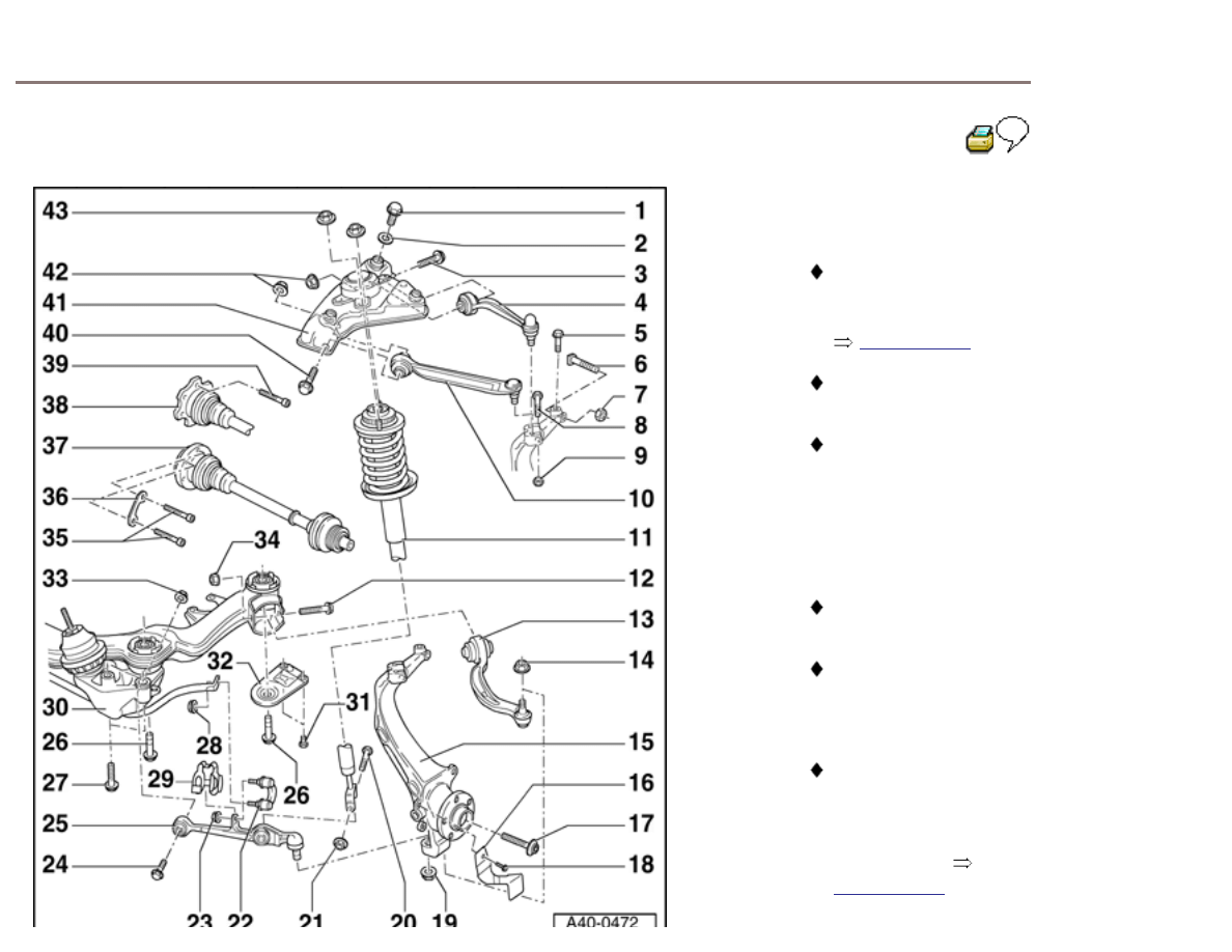
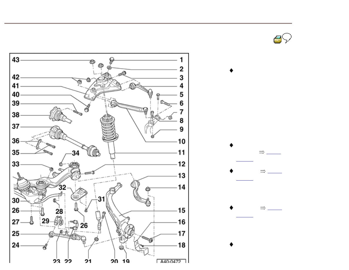
Front axle components, overview
General Information
Load bearing components and parts of the suspension
must not be welded or straightened.
Vehicles without drive axle must not be moved, or wheel
bearing will be damaged. If vehicle does have to be
moved, always note the following points:
-
Install an outer joint in place of the drive
axle.
-
Tighten outer joint to 115 Nm (M14 bolt) or 190 Nm
(M16 bolt).
Bonded rubber bushings can only be turned to a limited
extent. The bolted connections on suspension links
should only be tightened when vehicle is standing on
the ground.
Advanced
Search
Version: 2.5r01sp0003
Search
40-2
Threads in longmember, servicing
Servicing thread in weld nuts in longmember is possible
under certain circumstances.
Servicing must only be performed once per
thread.
If secondary servicing is required, the weld nut must
be replaced.
WARNING!
Wear protective glasses when drilling!
Have responsible foreman or next superior check
thread repair.
Thread insert must have same length as thread in
body.

Repair possible damage to underbody; applicable
notes can be found in:
Repair Manual, Body Collision Repair, Repair Group
00; Corrosion protection measures
40-3
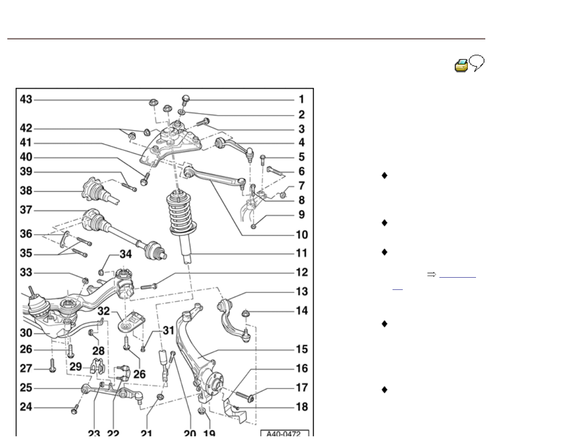
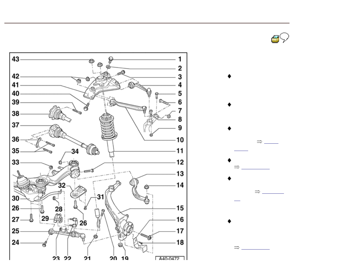
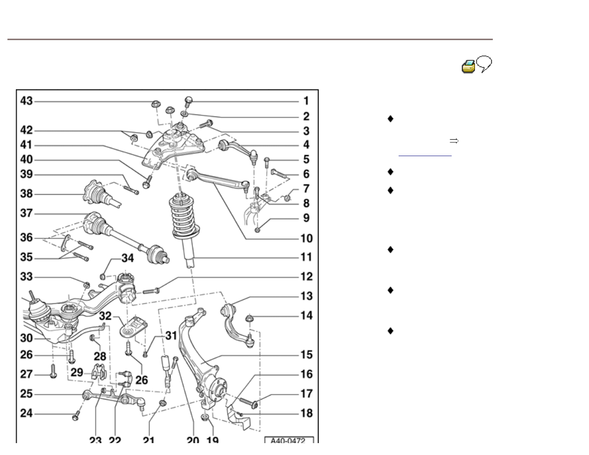
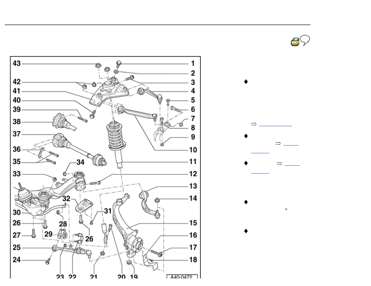
Component overview
1 - Hex bolt, 75 Nm
2 - Washer
3 - Hex bolt M10 x 62
Always replace
after disassembly
4 - Upper rear link
Replace
bushing
Separating from
wheel bearing
housing
Page 40-
15
5 - Hex bolt, 5 Nm
Bolt onto
system
6 - Bolt
7 - Self-locking nut
Always replace
after disassembly
50 Nm for steel
wheel bearing
housing
45 Nm for
aluminium wheel
bearing housing
8 - Hex bolt M10 x 100
40-4
9 - Self-locking nut, 40
Nm
Always replace
after disassembly
10 - Front upper link
Can be removed
together with
mounting bracket
Mounting bracket,
removing and
installing
Page
40-84
Replacing bushing
Page 40-84
Separating from
wheel bearing
housing
Page 40-
15
11 - Suspension strut
Note varying spring/
shock absorber
versions, see
vehicle data sticker
Page 40-27
Removing and
installing
Page
40-19
Servicing
Page
40-24
12 - Hex bolt M12 x 1.5 x
120
Always replace
after disassembly
40-5
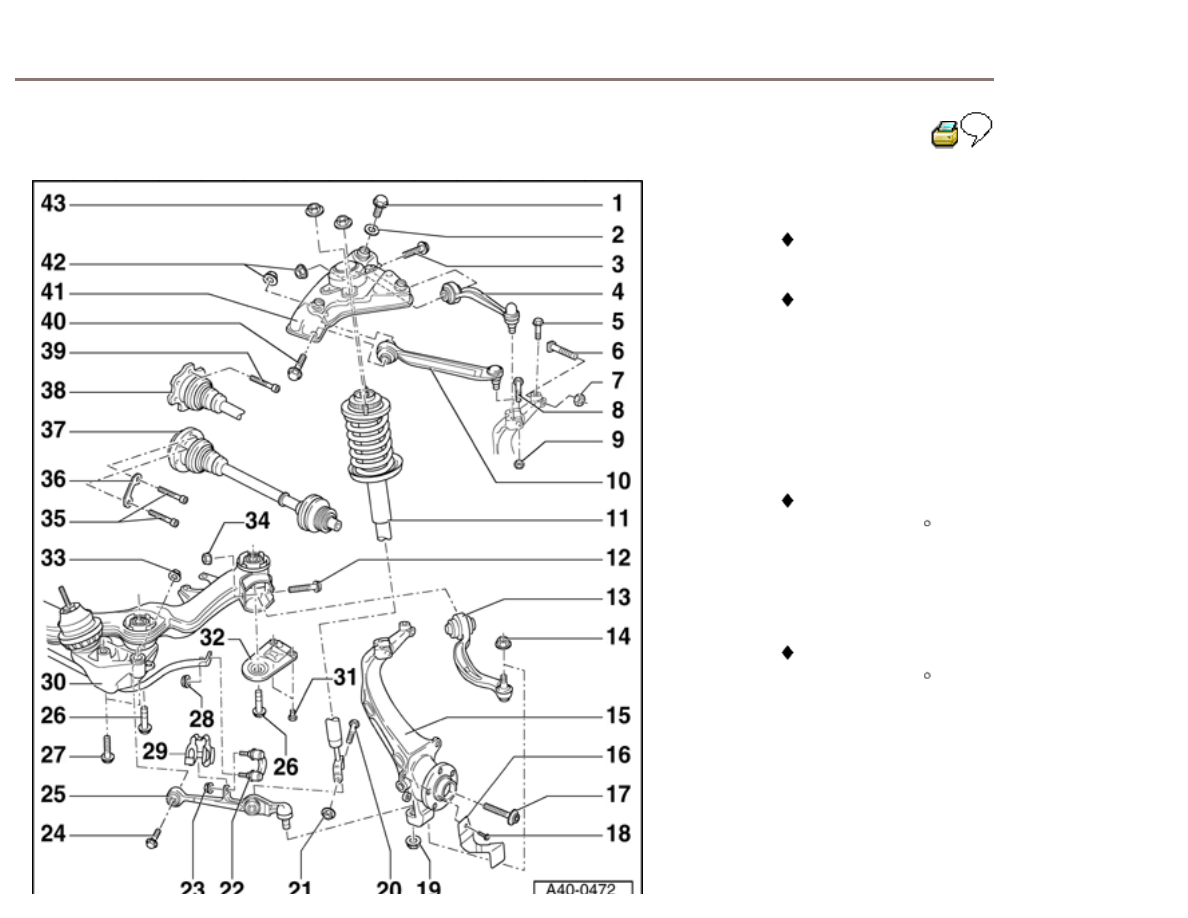
13 - Lower guide link
If anti-vibration
mount leaks it must
be replaced
Page 40-136
Application
See Parts
catalog
14 - Self-locking nut, 100
Nm
100 Nm for steel
wheel bearing
housing
110 Nm for
aluminium wheel
bearing housing
Always replace
after disassembly
15 - Wheel bearing
housing
There are versions
with and without a
groove for a ring on
the tie rod end -
only new version is
supplied as a
replacement part
On vehicles with a
headlight vertical
aim control system
be careful removing
and installing
Page 40-120
Removing and
installing
Page
40-35
Servicing
Page
40-42
Separating from
upper link
Page
40-15
16 - Backing plate
40-6
17 - Hex bolt
Always replace
after disassembly
Vehicle must not be
raised when
tightening
Tightening
torques:
Bolt
M14:
115 Nm plus
additional 180 (
1
/
2
-
turn)
Bolt
M16:
190 Nm plus
additional 180 (
1
/
2
-
turn)
18 - Socket head bolt, 10
Nm
19 - Self-locking nut, 100
Nm
100 Nm for steel
wheel bearing
housing
120 Nm for
aluminium wheel
bearing housing
Always replace
after disassembly
20 - Hex bolt M12 x 1.5 x
85
21 - Self-locking nut, 90
Nm
Always replace
after disassembly

40-7
22 - Coupling
Arrow on coupling
points in direction of
travel
Note change in
coupling and in
tightening torques
Page 40-144
23 - Self-locking hex nut
Always replace
after disassembly
40 Nm plus
additional 90 (
1
/
4
-
turn)
Nut has ribs on the
bottom
Only use this special
nut as replacement!
24 - Hex bolt M12 x 1.5 x
100
Always replace
after disassembly
40-8
25 - Lower track control
link
On vehicles with a
headlight vertical
aim control system
be careful removing
and installing
vehicle level sensor
Page 40-120
Removing and
installing
Page
40-117
Servicing
Page
40-126
26 - Hex bolt M12 x 1.5 x
110
110 Nm plus
additional 90 (
1
/
4
-
turn)
Always replace
after disassembly
Thread in body can
be repaired with
thread insert made
of wire according to
DIN 8140 (Helicoil).
Thread insert must
have same length
as thread in body.
27 - Hex bolt, 75 Nm
M10 X
70
Always replace
after disassembly
40-9
28 - Self-locking nut, 100
Nm
Note change in
coupling and in
tightening torques
Page 40-144
nut has ribs on the
bottom
Always replace
after disassembly
Only use this special
nut as replacement!
29 - Clip
inserted in track
control link
Always
replace
30 - Subframe
On vehicles with a
headlight vertical
aim control system
be careful removing
and installing
Page 40-120
Removing and
installing
Page
40-102
Servicing
Page
40-111

40-10
31 - Hex bolt, 25 Nm
Always replace
after removing
Observe different
bolt versions and
tightening torques
Fig. 6
Page
40-13
32 - Subframe support
33 - Self-locking nut
70 Nm plus
additional 180
1
/
2
turn
Always replace
after removing
34 - Self-locking nut
70 Nm plus
additional 180
1
/
2
turn
Always replace
after removing

40-11
35 - Socket-head bolt
Tightening
torques:
Bolt M8 X 48: 40
Nm
Bolt M10 X 48: 70
Nm
36 - Backing plate
37 - Drive axle
Removing and
installing
Page
40-147
Servicing
Page
40-151
38 - Drive axle with triple
roller joint
Servicing
Page
40-164
39 - Twelve-point socket
head bolt, 70 Nm
For vehicles with
triple roller joint
M10 X
20

40-12
40 - Hex bolt M10 x 62
Always replace
after disassembly
41 - Mounting bracket
Removing and
installing
Page
40-84
42 - Self-locking nut
50 Nm plus
additional 90 (
1
/
4
-
turn)
Always replace
after disassembly
43 - Self-locking nut with
flange, 20 Nm
Always replace
after disassembly

40-13
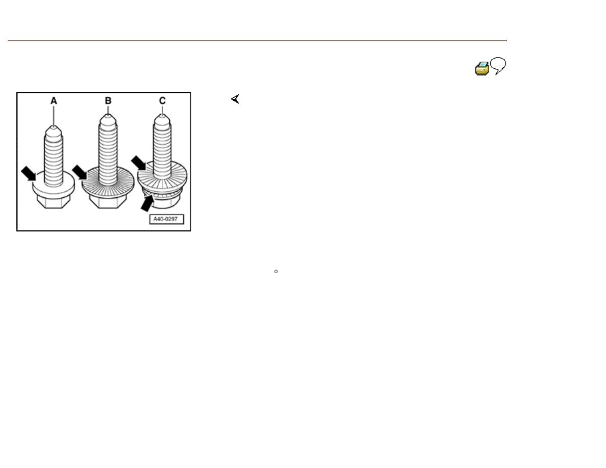
Fig. 6
Bolt
versions
Bolt -A- without ribbing.
Tightening torques: 25 Nm
Bolt -B- with ribbing.
Tightening torques: 75 Nm
Bolt -C- with screw head and washer ribbing.
Tightening torques: 30 Nmand turn an additional
90
All bolts must only be used once.
40-14
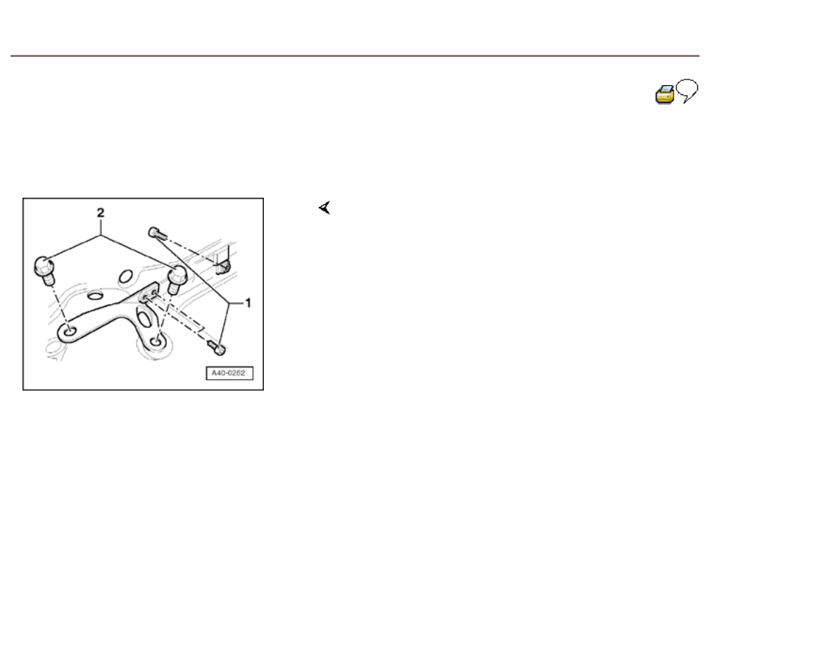
Mounting bracket with transverse beam,
removing and installing
To remove and install mounting bracket with transverse
beam, unscrew
-
Hex bolt -1- ( 1x behind
bulkhead)
-
Hex bolts -2-
( 4x )
Tightening torques
-
Hex bolts -
1-
Tightening torque 30
Nm
-
Hex bolts -
2-
Tightening torque 75
Nm
40-15
Upper link connection at wheel bearing
housing (steel), separating
This operation is only necessary if hex bolt for
connecting upper links to wheel bearing housing
cannot be removed.
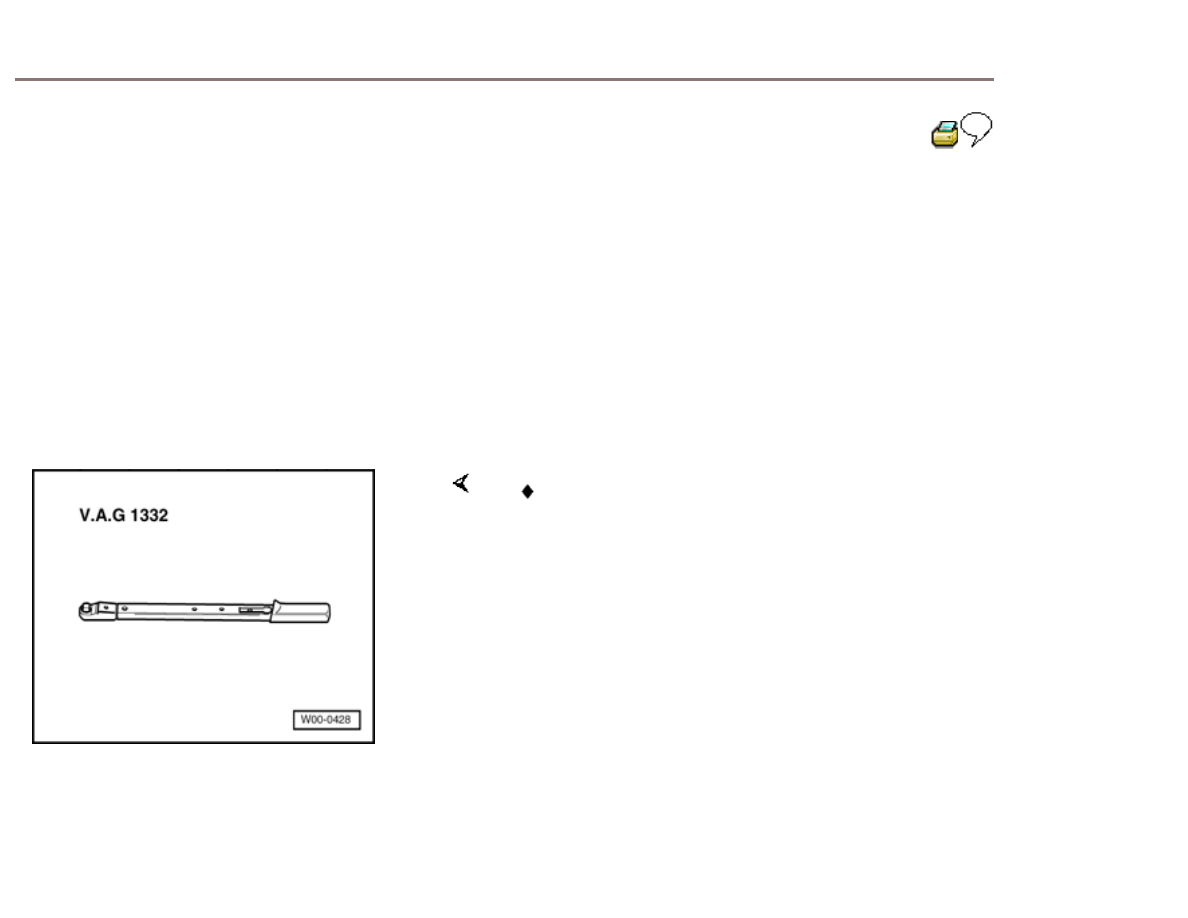
Special tools and equipment
V.A.G 1332 Torque
wrench
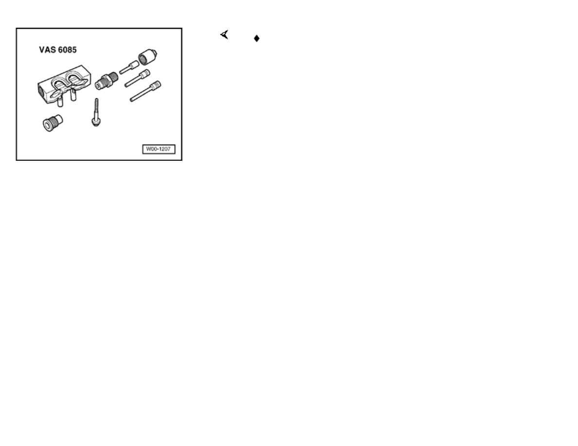
VAS 6085 Pressing-out
tool
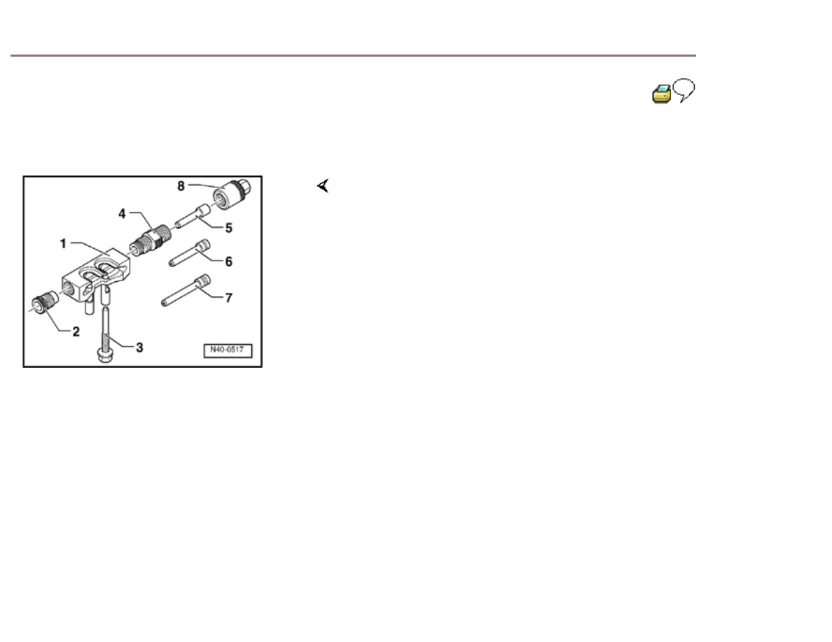
40-16
Removing
Pressing-out tool VAS 6085 components
1 -
Body
2 -
Adapter
3 - Thrust bolt M10 x 1.25 x
95
4 - Threaded
sleeve
5 - Press tool (length 78
mm)
6 - Press tool (length 98
mm)
7 - Press tool (length 118
mm)
8 -
Nut
Note:
Apply polycarbamide grease Part no. G 052 142 A2
before starting work to thrust bolt, press tools and nut.
-
Remove
wheel.
-
Disconnect ABS speed sensor wire out of holder at
brake caliper.
-
Unscrew nut -
1-.
Bolts -3- and -4- are never to be loosened.
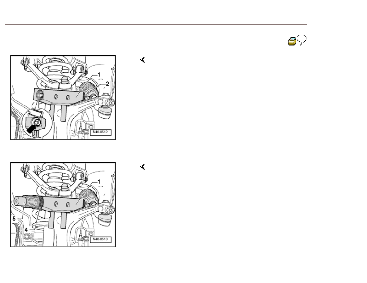
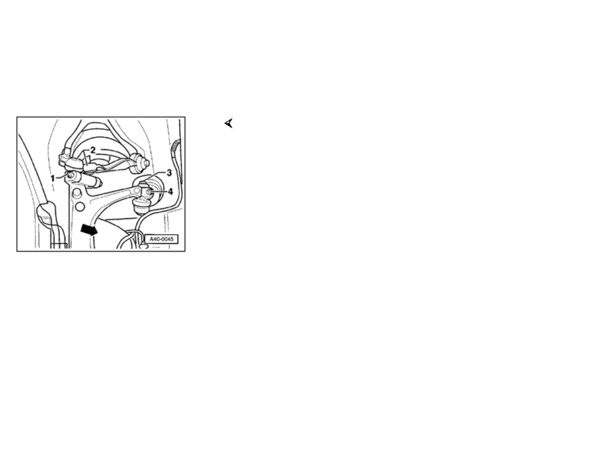
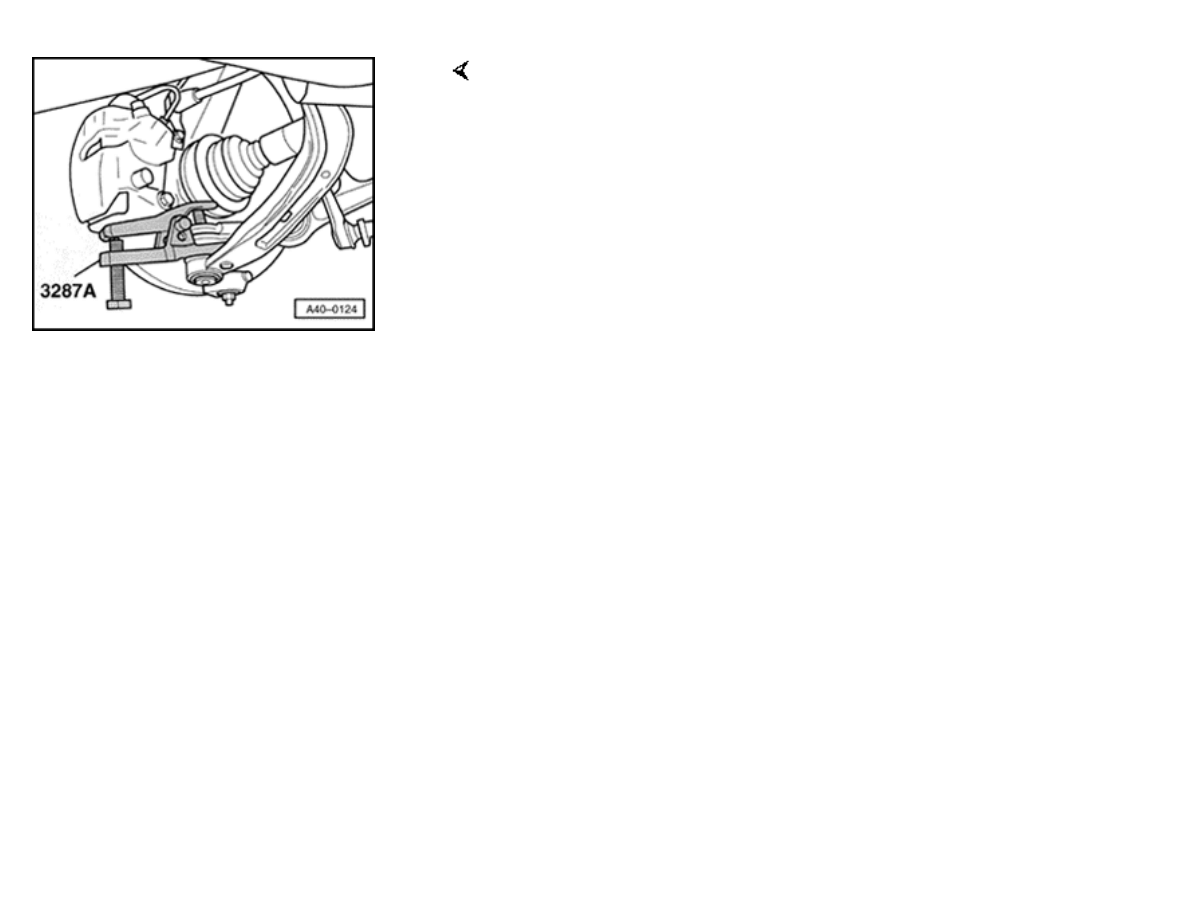
40-17
-
Position body -1- on wheel bearing housing. In doing
so, recesses engage beneath joints of links.
Note:
On inserting body, pay attention to boot as to avoid
damage.
-
Insert body -1- so that end of bolt (arrow) is centred
in hole in body.
-
Screw home adapter -2- in body -1- to lock
body.
-
Screw home threaded sleeve -4- in body -
1-.
-
Insert press tool -5- in threaded sleeve -
4-.
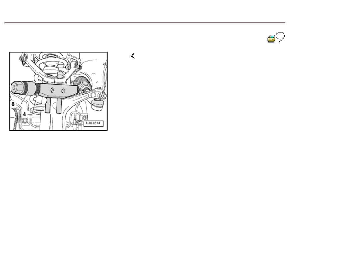
40-18
-
Screw nut -8- onto threaded sleeve -4- and turn as
far as it will go, thus pressing out bolt.
Note:
Use a wrench or an impact screwdriver to turn nut -8-.
-
Unscrew nut -8- from threaded sleeve -4-, take out
press tool -5- and insert press tool -6- in threaded
sleeve -4-.
-
Repeat pressing
operation.
-
If bolt can still not be taken out by hand, repeat
pressing operation with press tool -7-.
-
Unscrew nut -8- from threaded sleeve -4-. Take out
press tool and bolt.
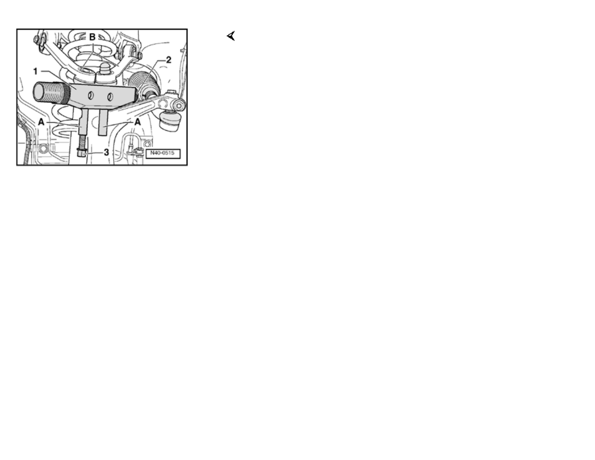
-
Screw thrust bolt -3- into one of the guides -A- in
each case and press links -B- out of wheel bearing
housing.
-
Screw thrust bolt -3- out of guide -A- and release
adapter -2-.
-
Detach body -1- from wheel bearing
housing.
j
a
t
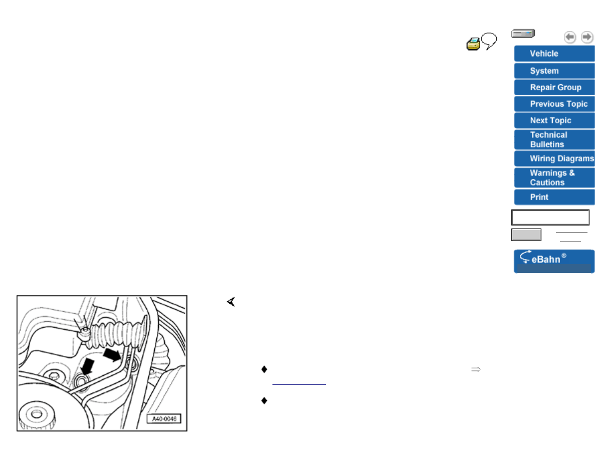
40-19
Suspension strut, removing and
installing
Removing
-
Remove cover plenum chamber /
battery
-
Remove hubcap, for light-alloy wheels pull off center
cap (use pulling hook in vehicle tools).
-
Remove
wheels.
-
Remove rubber grommets in plenum
(arrows).
Note:
For vehicles with headlight vertical aim control,
Page 40-120
.
In order not to damage joints of lower control arms,
it is necessary to use engine/transmission jack
VAG1383-A, for example, to brace against too
strong rebound.
Advanced
Search
Version: 2.5r01sp0003
Search
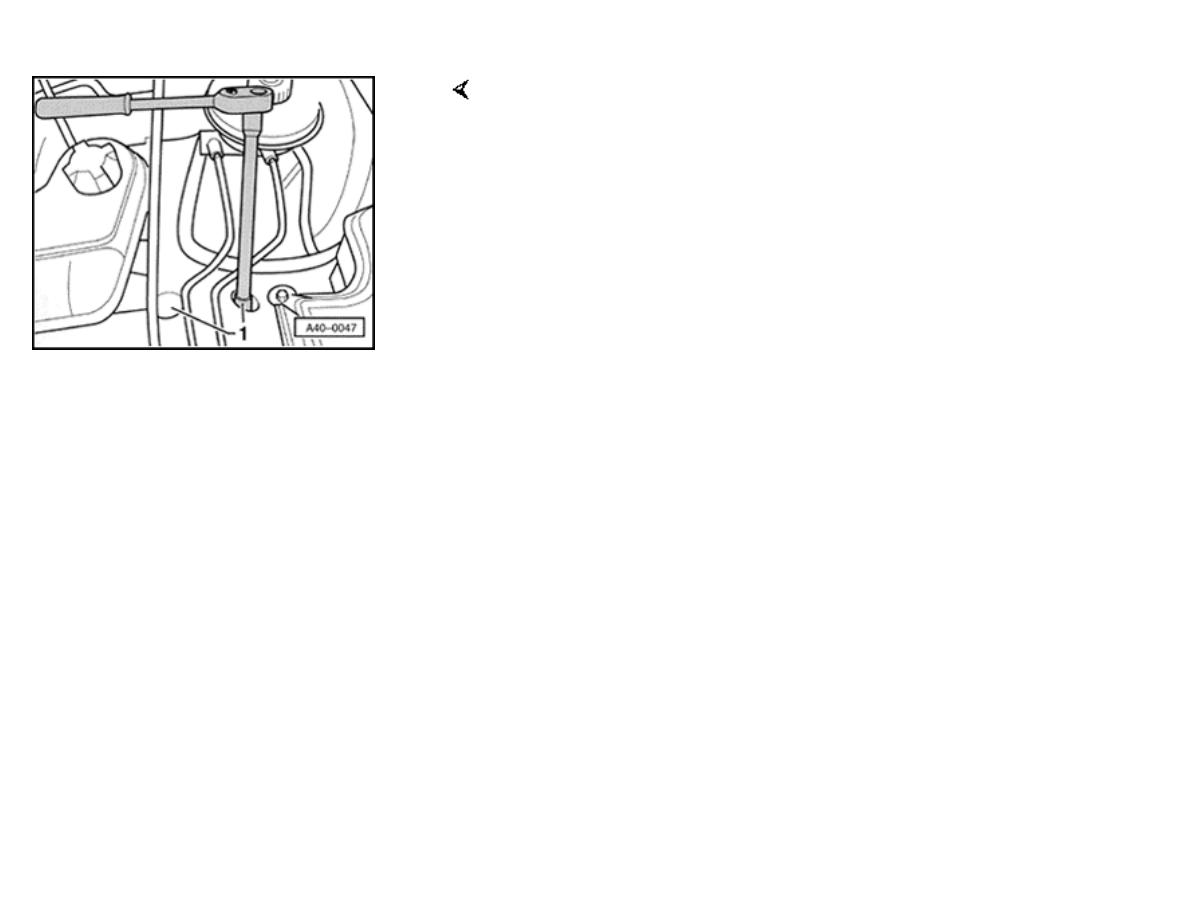
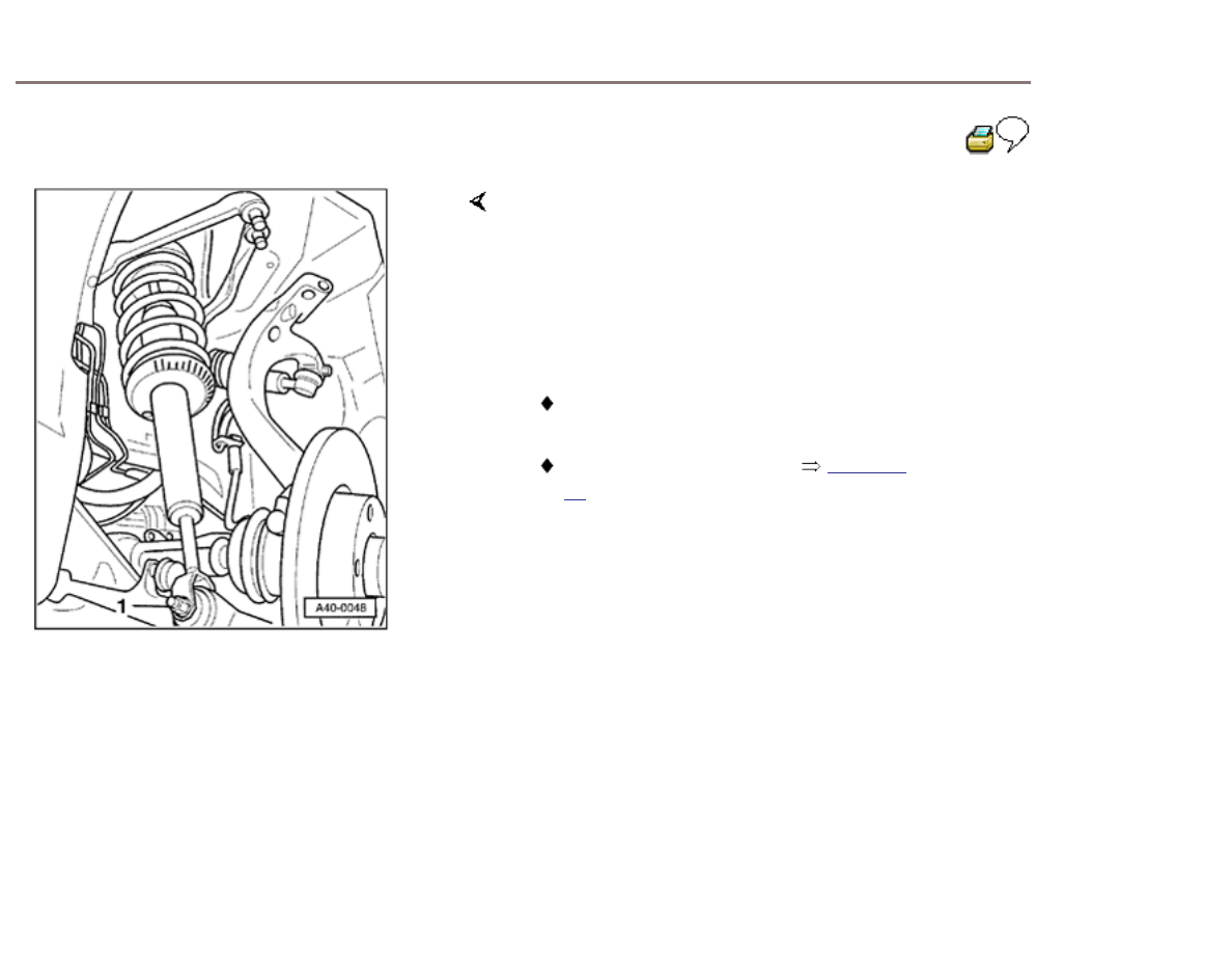
-
Unscrew suspension strut from
body.
1 -
Nuts
-
Pull cable of ABS wheel speed sensor out of bracket
on brake caliper.
Be careful not to damage surface of brake
lines!
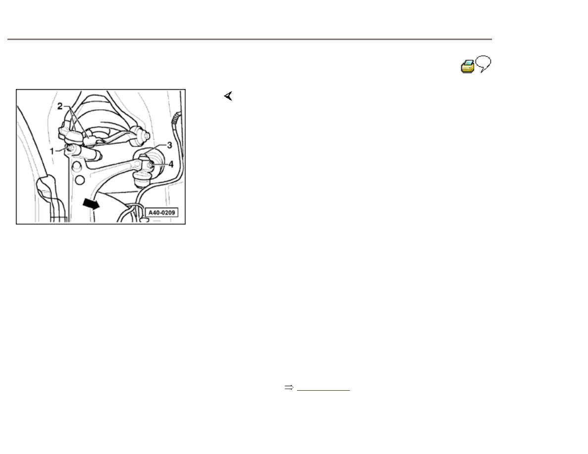
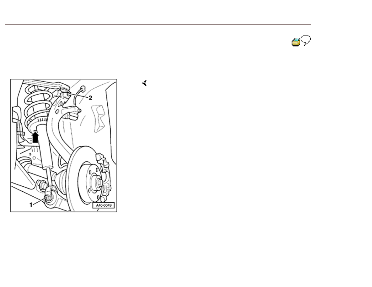
40-20
-
Unscrew nut -
1-.
Slits in wheel bearing housing may not be widened with
a chisel or similar tool!
-
Remove hex bolt and lift out link -
2-.
-
Swing away wheel bearing housing toward side, in
direction of (arrow).
Bolts -3- and -4- may not be loosened!
Otherwise wheel adjustment must be checked!
To unscrew hex bolt from suspension strut/track control
link, you must detach guide link from wheel bearing
housing.
Use 4 mm socket wrench to hold joint bolt, if
necessary.
-
On vehicles with an aluminum wheel bearing
housing be careful removing and installing guide
link,
Page 40-139
-
Unscrew guide link nut from joint bolt, then press off
joint bolt.
Be careful not to damage CV boot in the
process!
40-21
-
Unscrew bolt -1-, of suspension strut/track control
link.
-
Pull suspension strut down and
out.
Note:
Be careful not to damage CV boot when removing
suspension strut.
Servicing suspension strut
Page 40-
24
40-22
Installing
-
Put in suspension strut so that hole (arrow) in spring
seat faces middle of vehicle.
-
Bolt suspension strut together with track control
link.
Note:
Remove any adhesive remaining on thread of joint bolt.
-
Bonded rubber bushings can only be turned to a
limited extent. The suspension strut/track control link
bolt connection should only be tightened when
vehicle is standing on ground.
-
Tighten new nuts to 90
Nm.
-
Insert upper links in wheel bearing housing and
tighten new nuts -2- to 40 Nm.
-
Press upper links down as far as possible when
tightening!
-
Tighten nut on joint bolt to 100
Nm.

Use 4 mm socket wrench to hold joint bolt, if
necessary.

40-23
-
Insert cable of ABS wheel speed sensor into bracket
on brake caliper.
-
Screw on new bolts for suspension strut and tighten
to 20 Nm.
Be careful not to damage surface of brake
lines!
-
Put rubber grommets in
plenum.
-
Mount wheel and tighten to 120
Nm.
Wyszukiwarka
Podobne podstrony:
Bentley Audi A6 C5 EGT Testing
Bentley Audi A6 C5 Ignition
BentleyPublishers com Audi A6 C5 Service Reset
BentleyPublishers com Audi A6 C5 4 2L Secondary Air Injection Maintenance
BentleyPublishers com Audi A6 C5 Sunroof drain cleaning
BentleyPublishers com Audi A6 C5 4 2L Secondary Air Injection Maintenance
Audi A6 C5 2000 AirbagWiring
Instrukcja obslugi AUDI A6 C5 PL up by dunaj2
Audi A6 C5 Front Bumper Removal
Fourtitude com Audi A6 C5 Brake Information PartNumbers
Audi A6 C5 Podstawowe Informacje
Audi A6 C5 QuickReferenceGuide [4s]
Audi A6 C5 AirConditioner OutputDiagnosticTesting
AudiForums com Audi A6 C5 IceLink iPod Install
Instrukcja obslugi AUDI A6 C5 PL up by dunaj2
Audi A6 C5 Front Bumper Removal
Audi A6 C5 Climatronic ukryte menu serwisowe
AudiWorld com Audi A6 C5 Boor Blade Installation DIY
więcej podobnych podstron