
SECTION : 5B
FIVE–SPEED MANUAL TRANSAXLE
CAUTION : Disconnect the negative battery cable before removing or installing any electrical unit or when a tool
or equipment could easily come in contact with exposed electrical terminals. Disconnecting this cable will help
prevent personal injury and damage to the vehicle. The ignition must also be in LOCK unless otherwise noted.
TABLE OF CONTENTS
SPECIFICATIONS
5B–2
. . . . . . . . . . . . . . . . . . . . . . . . . .
FASTENER TIGHTENING
SPECIFICATIONS
5B–2
. . . . . . . . . . . . . . . . . . . . . . .
SPECIAL TOOLS
5B–3
. . . . . . . . . . . . . . . . . . . . . . . . . . .
SPECIAL TOOLS TABLE
5B–3
. . . . . . . . . . . . . . . . . . .
DIAGNOSIS
5B–5
. . . . . . . . . . . . . . . . . . . . . . . . . . . . . . . .
ISOLATE NOISE
5B–5
. . . . . . . . . . . . . . . . . . . . . . . . . .
SYMPTOM DIAGNOSIS
5B–6
. . . . . . . . . . . . . . . . . . . .
COMPONENT LOCATORS
5B–9
. . . . . . . . . . . . . . . . . .
GEARS AND CASE
5B–9
. . . . . . . . . . . . . . . . . . . . . . . .
DIFFERENTIAL AND CASE
5B–11
. . . . . . . . . . . . . . .
SHIFT LINKAGE
5B–12
. . . . . . . . . . . . . . . . . . . . . . . . .
MAINTENANCE AND REPAIR
5B–15
. . . . . . . . . . . . . .
ON–VEHICLE SERVICE
5B–15
. . . . . . . . . . . . . . . . . . . .
CHECKING FLUID LEVEL
5B–15
. . . . . . . . . . . . . . . . .
SHIFT LINKAGE ADJUSTMENT
5B–15
. . . . . . . . . . .
GEARSHIFT LEVER
5B–17
. . . . . . . . . . . . . . . . . . . . . .
GEARSHIFT TUBE, BOOT, BUSHING
AND/OR BEARING RING
5B–18
. . . . . . . . . . . . . . . .
CONTROL SHIFT ROD
5B–23
. . . . . . . . . . . . . . . . . . .
LINKAGE LEVER AND/OR BUSHINGS
5B–24
. . . . .
SPEEDOMETER DRIVEN GEAR
5B–30
. . . . . . . . . . .
SHIFT LEVER COVER
5B–32
. . . . . . . . . . . . . . . . . . . .
DRIVE AXLE SEAL
5B–34
. . . . . . . . . . . . . . . . . . . . . . .
TRANSAXLE ASSEMBLY
5B–34
. . . . . . . . . . . . . . . . .
UNIT REPAIR
5B–42
. . . . . . . . . . . . . . . . . . . . . . . . . . . . .
MAJOR COMPONENT DISASSEMBLY
5B–42
. . . . .
INPUT SHAFT AND CLUSTER GEAR
5B–53
. . . . . .
MAINSHAFT
5B–56
. . . . . . . . . . . . . . . . . . . . . . . . . . . . .
HOUSING CASE
5B–71
. . . . . . . . . . . . . . . . . . . . . . . . .
DIFFERENTIAL
5B–74
. . . . . . . . . . . . . . . . . . . . . . . . . .
MAJOR COMPONENT ASSEMBLY
5B–82
. . . . . . . . .
GENERAL DESCRIPTION AND SYSTEM
OPERATION
5B–91
. . . . . . . . . . . . . . . . . . . . . . . . . . . . .
FIVE–SPEED MANUAL TRANSAXLE
5B–91
. . . . . . .
5B – 2
I
FIVE–SPEED MANUAL TRANSAXLE
DAEWOO V–121 BL4
SPECIFICATIONS
FASTENER TIGHTENING SPECIFICATIONS
Application
N
S
m
Lb–Ft
Lb–In
Backup Lamp Switch
18
13
Bearing Plate Bolts
22
16
Bearing Retainer Bolts, Right Side
25
18
Bearing–Adjusting Ring–Retainer Plate Bolt
25
18
Center Rear Transaxle Support Bracket Bolts
93
69
Clutch–Release Cylinder Bracket Bolts
75
55
Differential Cover Bolts
40
30
Fifth–Gear Fork Bolts
22
16
Fifth–Gearshift Connector Bolts
7
62
Gearshift Lever Cover Bolts
22
16
Input Driveshaft Detent Screw
15
11
Left Front Transaxle Support Bracket Bolts
47
35
Left Rear Transaxle Support Bracket Bolts
47
35
Lower Transaxle–to–Engine Bolts
75
55
Ring–Gear Bolts
70
52
Rod Clamp Bolt
14
124
Speedometer Housing Retaining Bolt
4
35
Speedometer–Driven Gear Bolt
5
44
Support Bracket Bolt
7
62
Transaxle Cover Bolts, Bigger
20
15
Transaxle Cover Bolts, Smaller
15
11
Upper Transaxle–to–Engine Bolts
75
55
FIVE–SPEED MANUAL TRANSAXLE 5B – 3
DAEWOO V–121 BL4
SPECIAL TOOLS
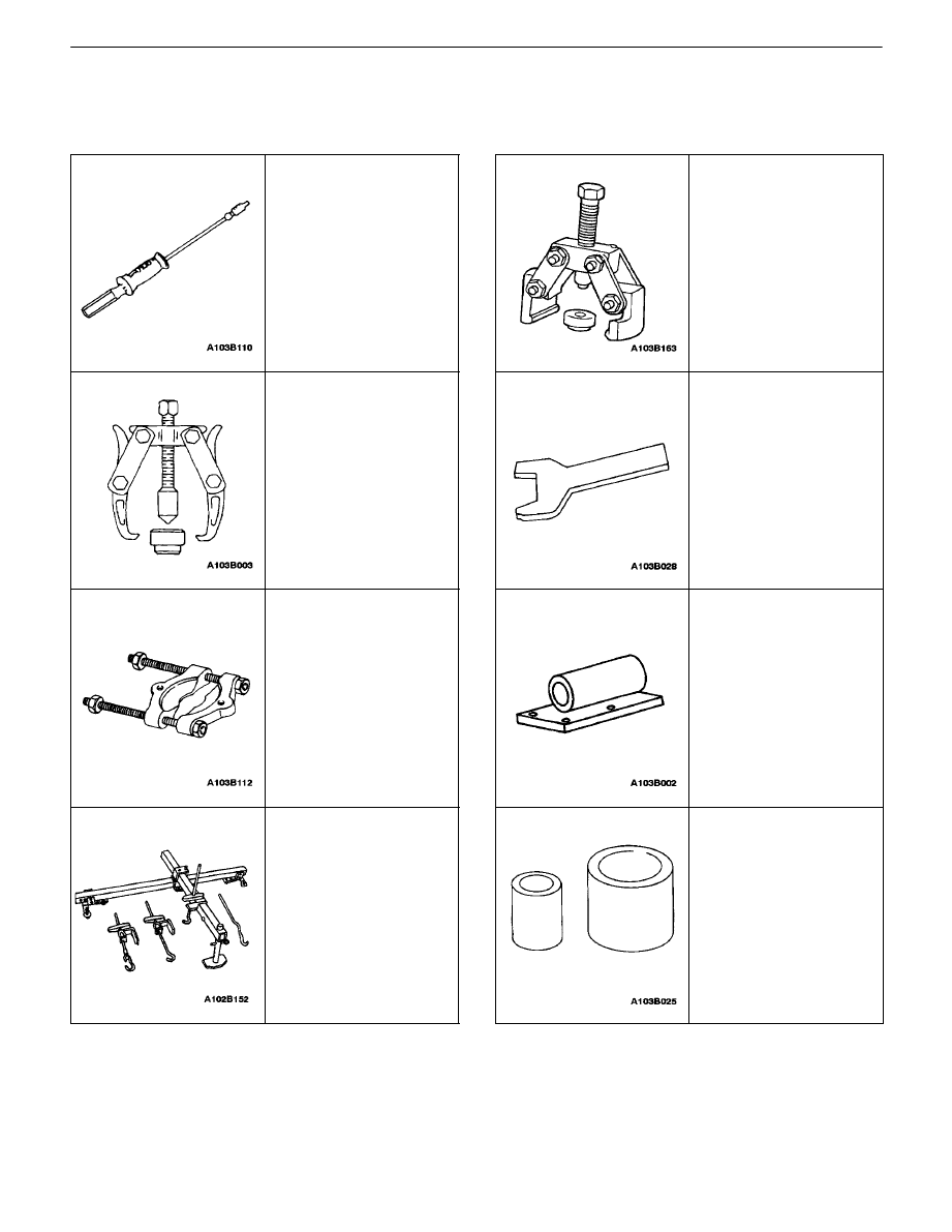
SPECIAL TOOLS TABLE
J–6125–B
Slide Hammer
J–22888–20–A
Bearing Puller with
J–22888–35
Puller Legs
J–22912–01
Universal Bearing
Puller
J–28467–B
Engine Support Fixture
KM–553–A
Fifth–Gear Puller
J–36633
Snap Ring Retainer
KM–113–2
Base
KM–334
Installer Sleeve
5B – 4
I
FIVE–SPEED MANUAL TRANSAXLE
DAEWOO V–121 BL4
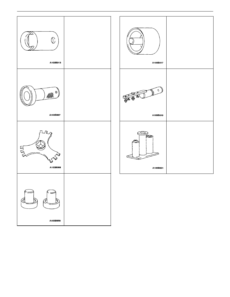
J–42469
Shift Rod Remover
KM–519
Ring Installer
KM–520
Remover/Installer
KM–522
Installer
KM–525
Installer
KM–552
Fixture
KM–554
Installer

FIVE–SPEED MANUAL TRANSAXLE 5B – 5
DAEWOO V–121 BL4
DIAGNOSIS
ISOLATE NOISE
Identify the cause of any noise before attempting to repair
the clutch, the transaxle, or their related linkages.
Symptoms of trouble with the clutch or the manual trans-
axle include:
S
A great effort required to shift gears.
S
The sound of gears clashing and grinding.
S
Gear
blockout.
Any of these conditions requires a careful analysis. Make
the following checks before disassembling the clutch or
the transaxle for repairs.
Road Travel Noise
Many noises that appear to come from the transaxle may
actually originate with other sources such as the:
S
Tires.
S
Road
surfaces.
S
Wheel
bearings.
S
Engine.
S
Exhaust
system.
These noises may vary according to the:
S
Size of the vehicle.
S
Type of the vehicle.
S
Amount of insulation used in the body of the ve-
hicle.
Transaxle Noise
Transaxle gears, like any mechanical device, are not ab-
solutely quiet and will make some noise during normal op-
eration.
To verify suspected transaxle noises:
1. Select a smooth, level asphalt road to reduce tire
and resonant body noise.
2. Drive the vehicle far enough to warm up all the lu-
bricants thoroughly.
3. Record the speed and the gear range of the trans-
axle when the noise occurs.
4. Check for noises with the vehicle stopped, but with
the engine running.
5. Determine if the noise occurs while the vehicle op-
erates in:
S
Drive – under a light acceleration or a heavy
pull.
S
Float – maintaining a constant speed with a light
throttle on a level road.
S
Coast – with the transaxle in gear and the
throttle partly or fully closed.
S
All of the above.
Bearing Noise
Differential Side Bearing Noise
Differential side bearing noise and wheel bearing noise
can be confused easily. Since side bearings are pre-
loaded, a differential side bearing noise should not dimin-
ish much when the differential/transaxle is run with the
wheels off the ground.
Wheel Bearing Noise
Wheel bearings produce a rough growl or grating sound
that will continue when the vehicle is coasting and the
transaxle is in NEUTRAL. Since wheel bearings are not
pre–loaded, a wheel bearing noise should diminish con-
siderably when the wheels are off the ground.
Other Noise
Brinelling
A brinelled bearing causes a ”knock” or ”click” approxi-
mately every second revolution of the wheel because the
bearing rollers do not travel at the same speed as the
wheel. In operation, the effect is characterized by a low–
pitched noise.
A brinelled bearing is caused by excessive thrust which
pushes the balls up on the pathway and creates a triangu-
lar– shaped spot in the bearing race. A brinelled bearing
can also be caused from pressing one race into position
by applying pressure on the other race.
A false indication of a brinelled bearing occurs as a result
of vibration near the area where the bearing is mounted.
Brinelling is identified by slight indentations, resulting in a
washboard effect in the bearing race.
Lapping
Lapped bearing noise occurs when fine particles of abra-
sive materials such as scale, sand, or emery circulate
through the oil in the vehicle, causing the surfaces of the
roller and the race to wear away. Bearings that wear loose
but remain smooth, without spalling or pitting, are the re-
sult of dirty oil.
Locking
Large particles of foreign material wedged between the
roller and the race usually causes one of the races to turn,
creating noise from a locked bearing. Pre–loading regular
taper roller bearings to a value higher than that specified
also can result in locked bearings
Pitting
Pitting on the rolling surface comes from normal wear and
the introduction of foreign materials.
Spalling
Spalled bearings have flaked or pitted rollers or races
caused by an overload or an incorrect assembly that re-
sults in a misalignment, a cocking of bearings, or adjust-
ments that are too tight.
After completing these checks, refer to the ”Diagnosis
Chart” in this section.

5B – 6
I
FIVE–SPEED MANUAL TRANSAXLE
DAEWOO V–121 BL4
SYMPTOM DIAGNOSIS
Checks
Action
Check for a knock at low speeds.
S
Replace any worn drive axle CV joints.
S
Replace any worn side gear hub.
Check for a noise most pronounced on turns.
S
Correct any abnormalities in the differential gear.
Check for a clunk upon acceleration or deceleration.
S
Tighten any loose engine mounts.
S
Replace any worn drive axle inboard joints.
S
Replace any worn differential pinion shaft in the
case.
S
Replace any worn side gear hub in the case.
Check for a clunking noise in turns.
S
Replace any worn outboard CV joint.
Check for a vibration.
S
Replace any rough wheel bearing.
S
Replace any bent drive axle shaft.
S
Replace any out–of–round tires.
S
Balance any unbalanced tire.
S
Replace any worn CV joint in the drive axle shaft.
S
Correct an excessive drive axle angle by adjusting
the trim height.
Check for a noise in the NEUTRAL gear with the engine
running.
S
Replace any worn cluster bearing shaft.
S
Replace any worn clutch–release bearing.
S
Replace any worn input shaft cluster gears.
S
Replace any worn first–gear/bearing.
S
Replace any worn second–gear/bearing.
S
Replace any worn third–gear/bearing.
S
Replace any worn fourth–gear/bearing.
S
Replace any worn fifth–gear/bearing.
S
Replace any worn mainshaft bearings.
Check for a noise in the first gear (1) only.
S
Replace any chipped, scored, or worn first–gear
constant mesh gears.
S
Replace any worn first–second gear synchronizer.
S
Replace any worn first–gear/bearing.
S
Replace any worn differential–gear/bearing.
S
Replace any worn–ring gear.
S
Adjust, repair, or replace the shift lever and the rods.
Check for a noise in the second gear (2) only.
S
Replace any chipped, scored, or worn second–gear
constant mesh gears.
S
Replace any worn first–second gear synchronizer.
S
Replace any worn second–gear/bearing.
S
Replace any worn differential–gear/bearing.
S
Replace any worn–ring gear.
S
Adjust, repair, or replace the shift lever and the rods.
Check for a noise in the third gear (3) only.
S
Replace any chipped, scored, or worn third–gear
constant mesh gears.
S
Replace any worn third–fourth gear synchronizer.
S
Replace any worn third–gear/bearing.
S
Replace any worn differential–gear/bearing.
S
Replace any worn–ring gear.
S
Adjust, repair, or replace the shift lever and the rods.

FIVE–SPEED MANUAL TRANSAXLE 5B – 7
DAEWOO V–121 BL4
Checks
Action
Check for a noise in the fourth gear (4) only.
S
Replace any chipped, scored, or worn fourth gear or
output gear.
S
Replace any worn third–fourth gear synchronizer.
S
Replace any worn fourth–gear/bearing.
S
Replace any worn differential–gear/bearing.
S
Replace any worn–ring gear.
S
Adjust, repair, or replace the shift lever and the rods.
Check for a noise in the fifth gear (5) only.
S
Replace any chipped, scored, or worn fifth gear or
output gear.
S
Repair any worn fifth–gear synchronizer.
S
Replace any worn fifth–gear/bearing.
S
Replace any worn differential–gear/bearing.
S
Replace any worn–ring gear.
S
Adjust, repair, or replace the shift lever and the rods.
Check for a noise in the reverse (R) gear only.
S
Replace any chipped, scored, or worn reverse idler
gear, idler–gear bushing, input gear, or output gear.
S
Replace any worn first–second gear synchronizer.
S
Replace any worn output gear.
S
Replace any worn differential–gear/bearing.
S
Replace any worn–ring gear.
Check for a noise in all gears.
S
Add
sufficient
lubricant.
S
Replace any worn bearings.
S
Replace any chipped, scored, or worn input–gear
shaft or output–gear shaft.
Check for the transaxle slipping out of gear.
S
Adjust or replace the linkage, as needed.
S
Adjust, repair, or replace any binding shift linkage.
S
Tighten or replace the input–gear bearing retainer, as
needed.
S
Repair or replace any worn or bent shift fork.
Check for a leak in the area of the clutch.
S
Repair the transaxle casing.
S
Replace any damaged release bearing guide.
Check for a leak at the center of the transaxle.
S
Repair the transaxle casing.
S
Repair the shift mechanism.
S
Replace the damaged backup lamp switch.
Check for a leak at the differential.
S
Adjust or replace the bearing retainers.
S
Tighten or replace the differential cover.
S
Adjust or replace the drive axle shaft seals.
Check for a hard shift.
S
Replace any damaged release–bearing guide.
S
Adjust, repair, or replace the shift mechanism.
S
Adjust, repair, or replace the clutch–release system.
S
Replace any chipped, scored, or worn fifth–gear syn-
chronizer.
S
Replace any chipped, scored, or worn first–second
gear synchronizer.
S
Replace any worn third–fourth gear synchronizer.
S
Adjust, repair, or replace the shift lever and the rods.
5B – 8
I
FIVE–SPEED MANUAL TRANSAXLE
DAEWOO V–121 BL4
Checks
Action
Check for a clashing of gears.
S
Replace any damaged release–bearing guide.
S
Adjust, repair, or replace the clutch–release system.
S
Replace the chipped, scored, or worn input shaft/
gear–cluster gears.
S
Replace any worn fifth–gear synchronizer.
S
Replace any worn fifth–gear/bearing.
S
Replace any worn first–gear/bearing.
S
Replace any worn first–second gear synchronizer.
S
Replace any worn second–gear/bearing.
S
Replace any worn third–gear/bearing.
S
Replace any worn third–fourth synchronizer.
S
Replace any worn fourth–gear/bearing.
S
Replace any worn reverse–idler gear.
FIVE–SPEED MANUAL TRANSAXLE 5B – 9
DAEWOO V–121 BL4
COMPONENT LOCATORS
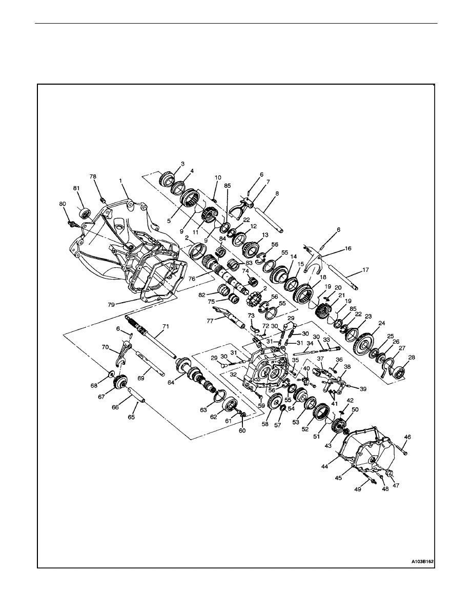
GEARS AND CASE

5B – 10
I
FIVE–SPEED MANUAL TRANSAXLE
DAEWOO V–121 BL4
1. Case
2. Mainshaft
Bearing
3. Fourth
Gear
4. Synchronizer Blocking Ring
5. Synchronizer
Sleeve
6. Pin
7. Third–Fourth Gearshift Fork
8. Third–Fourth Gearshift Shaft
9. Spring
10. Key
11. Third–Fourth Synchronizer Gear
12. Synchronizer Blocking Ring
13. Third Gear
14. Second Gear
15. First–Second Gear Blocking Ring
16. First–Second Gearshift Fork
17. First–Second Gearshift Shaft
18. Synchronizer Hub Sleeve
19. Synchronizer Spring
20. Key
21. First–Second Synchronizer Gear
22. Snap Ring
23. Outer Blocking Ring
24. First Gear
25. First Gear Needle Bearing
26. Mainshaft Wear Plate
27. Snap Ring
28. Mainshaft Bearing
29. Shift Rod Plug (21.5 mm)
30. Spring
31. Shift Rod Lock Pin
32. Bearing Plate
33. Shift Rod Plug (50.4 mm)
34. Detent Rod Bolt
35. Bolt
36. Bolt
37. Support
38. Fifth Gearshift Fork
39. Pin
40. Fifth Gear Connector
41. Shoe
42. Key
43. Snap Ring
44. Gasket
45. Cover
46. Bolt
47. Plug
48. Bolt
49. Screw
50. Synchronizer Gear
51. Spring
52. Synchronizer Sleeve
53. Synchronizer Blocking Ring
54. Mainshaft Driven Fifth Gear
55. Ring
56. Thrust Washer
57. Ring
58. Input Drive Fifth Gear
59. Bolt
60. Cluster Gear Snap Ring
61. Screw
62. Cluster Shaft Bearing
63. Ring
64. Input Shaft Cluster Gear
65. Ball
66. Reverse Idler Gear Shaft
67. Reverse Idler Gear
68. Washer
69. Reverse Gear Fork Shaft
70. Reverse Gearshift Fork
71. Input Drive Shaft
72. Bolt
73. Fifth–Gear Pawl
74. Fifth–Gear Needle Bearing
75. First–Gear Needle Bearing
76. Main Driven Shaft
77. Fifth Gearshift Lever
78. Hex Plug
79. Gasket
80. Reverse Lamp Switch
81. Input Shaft Bearing
82. Second–Gear Needle Bearing
83. Third–Gear Needle Bearing
84. Fourth–Gear Needle Bearing
85. Washer
FIVE–SPEED MANUAL TRANSAXLE 5B – 11
DAEWOO V–121 BL4
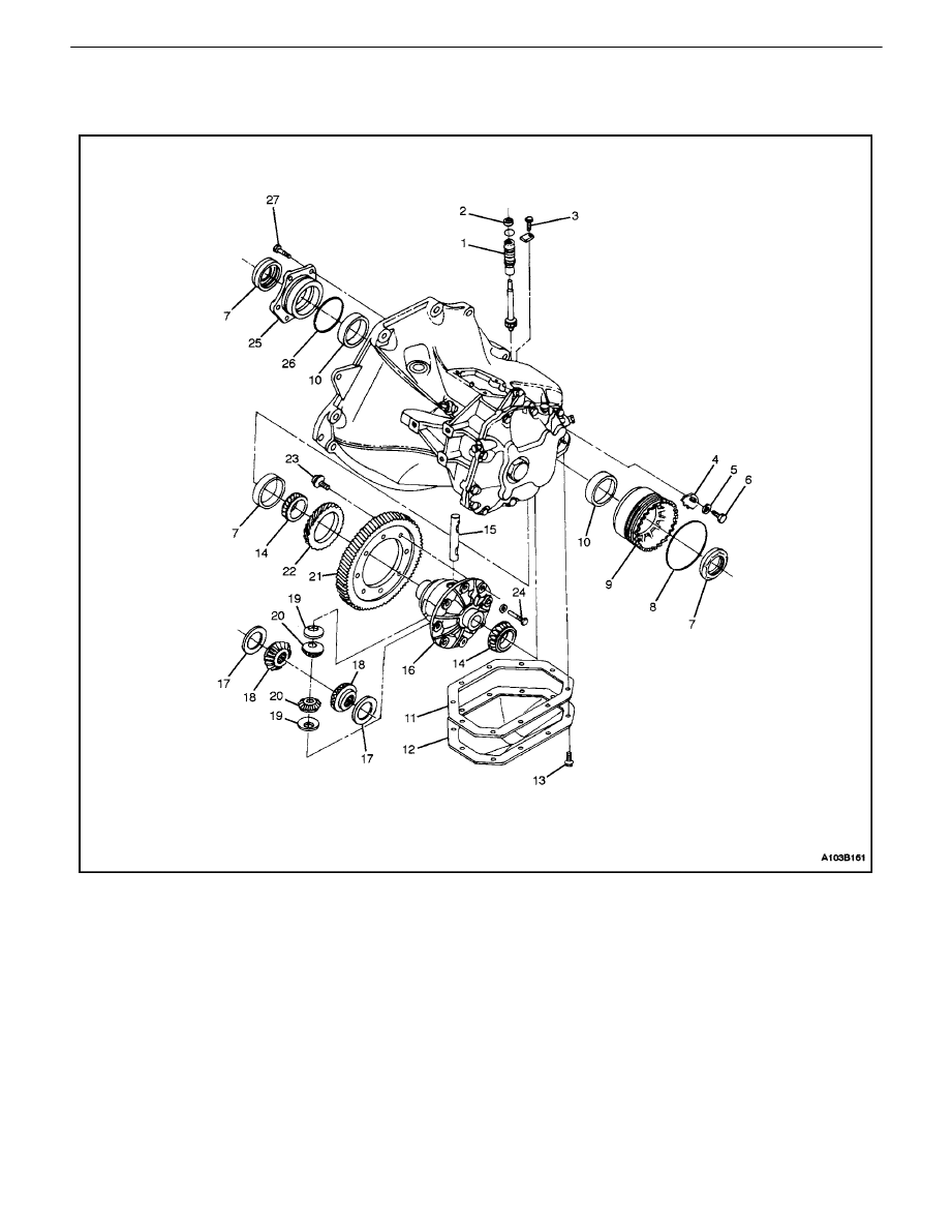
DIFFERENTIAL AND CASE
1. Speedometer–Driven
Gear
2. Seal
3. Hex
Bolt
4. Bearing
Plate
5. Washer
6. Bolt
7. Seal
8. Seal
9. Bearing Adjusting Ring
10. Side Bearing Race
11. Housing Cover Gasket
12. Differential Cover
13. Bolt
14. Differential Bearing
15. Pinion Gear Shaft
16. Differential Housing
17. Thrust Washer
18. Side Gear
19. Washer
20. Pinion Gear
21. Ring Gear
22. Speedometer Drive Gear
23. Bolt
24. Pinion Shaft Lock Pin
25. Right Side Bearing Retainer
26. Seal
27. Retainer Bolt
5B – 12
I
FIVE–SPEED MANUAL TRANSAXLE
DAEWOO V–121 BL4
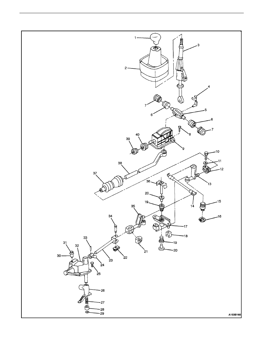
SHIFT LINKAGE

FIVE–SPEED MANUAL TRANSAXLE 5B – 13
DAEWOO V–121 BL4
1. Gearshift Lever Knob
2. Gearshift Lever Boot
3. Gearshift
Lever
4. Gearshift Lever Stop Clamp
5. Gearshift Lever Shaft
6. Gearshift Lever Stop Bushing
7. Gearshift Lever Stop Bushing
8. Bolt
9. Gearshift
Housing
10. Shift Rod Clamp Bolt
11. Washer
12. Clamp
13. Linkage Adjuster Bolt
14. Gearshift Control Rod
15. Linkage Ball Socket
16. Circlip Ring
17. Linkage Reverse Lever
18. Gearshift Boot
19. Bushing
20. Bushing
21. Rod U–Joint Bushing
22. Clip
23. Gearshift Rod
24. Shift Finger Lever
25. Cover Bolt
26. Intermediate Lever
27. Shift Lever Thrust Spring
28. Bushing
29. Snap Ring
30. Oil Filler Plug
31. Oil Plug Cap
32. Gearshift Lever Cover
33. Pin
34. Bolt
35. Gearshift Adjuster Linkage
36. Shift Reverse Pivot Bolt
37. Boot
38. Gearshift Tube
39. Bushing
40. Gearshift Tube Bearing
Wyszukiwarka
Podobne podstrony:
M35b Five Speed Manual Transaxle
06 MANUAL TRANSAXLE (C153)(1)
13 manual transaxle
ARTICLE MANUAL TRANSAXLE DISASSMEBLY
M33b Manual Transaxle Drive Axle
ARTICLE MANUAL TRANSAXLE ASSMEBLY
06 MANUAL TRANSAXLE (C153)(1)
AUTOMATIC TRANSAXLE SECTION 5A 18
06 MANUAL TRANSAXLE (C153)(1)
41 Manual Transmission Transaxle
NX650 Y Section 22 Service manual Index
Mazda 6 (Mazda6) Automatic Transaxle Workshop Manual Supplement JA5AX EL
MANUAL TRANSMISSION & TRANSAXLE
NX650 Y Section 22 Service manual Index
więcej podobnych podstron