Features
ARTCHIP
SEMICONDUCTOR
ART3653A
9Aa : Product code
LL : Lot code or datecode abbreviation (From A~Z)
ORDERING INFORMATION
Device
Marking Code
Package
Shipping
†
ART3653A
9AaLL
3000 / Tape & Reel
1
5
1
3
2
4
5
SOT23 5
9AaLL
-
SOT23 5
-
1
3
2
FB
4
Vcc
5
(Top View)
CS
GND
Vout
POWER MANAGEMENT
Primary Side Control CC/CV Controller
Constant-Current (CC) and Constant-Voltage
(CV) Control with Primary Side Control
±
5% Constant Voltage Regulation
±
10% Constant Current Regulation
Eliminates Opto-Coupler and TL431
External Power NPN Transistor for Low Cost
Operation Frequency Modulation Improve
System EMI
Built-in Line Compensation
Cycle-by-Cycle Current Limiting
Over Voltage Protection (OVP)
Over Temperature Protection (OTP)
Open Circuit Protection
Short Circuit Protection
Pb-Free Device
•
•
•
•
•
•
•
•
•
•
•
•
•
The 3653A controller device is optimized for low
cost, low power switching mode power supply
applications that not needed cable compensation .
The 3653A facilitates CC/CV charger design by
eliminating an opto-coupler and TL431. Its highly
integrated functions such as Under Voltage Lockout
(UVLO), Leading Edge Blanking (LEB), Buit-in line
compensation and Cycle-by-Cycle current limiting
offer the users a high efficiency and low cost solution
for AC/DC power applications.
Furthermore, 3653A features fruitful protections
like OTP (Over Temperature Protection), OVP (Over
Voltage Protection), and Open Circuit Protection,
Short Circuit Protection to eliminate the external
protection circuits and provide reliable operation.
ART3653A is available in SOT23-5 packages.
TYPICAL APPLICATION
Adapter/Charger for Cell/Cordless Phones,
PDAs, MP3 and Other Portable Apparatus
Standby and Auxiliary Power Supplies
Set Top Boxes (STB)
LED Driver
•
•
•
•
•
©
1
@ Artchip Semiconductor , 2008
V1.3 2011
ARTCHIP
SEMICONDUCTOR
ART3653A
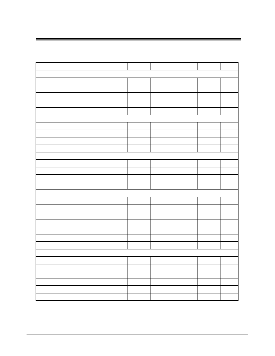
ELECTRICAL CHARACTERISTICS
(For typical values Tj=25℃, Vcc=10V, unless otherwise noted)
Characteristic Symbol
Min
Typ
Max
Unit
Current Sense
Maximum Current Threshold
Vcs_max
0.49
0.5
0.51
V
Pre-drive Current Threshold
Vcs_pre
0.44
0.45
0.46
V
Vcs_limit Temperature Stability
(-40℃~125℃)
1
%
Leading Edge Blanking Duration
Tleb
400 ns
Propagation Delay (OUT=1.0nF to GND)
Tpd
200 ns
Feedback Section
Feedback Voltage Threshold
Vfb
2.97
3
3.03
V
FB Pin minimum current
Ifb_open
50
μA
OVP Protection Threshold Level
Vovp
4.55
4.65
4.75
V
CCM protection Threshold Level
Vcp
0.1
V
Supply Section
Start Up Threshold Voltage
Vcc_on
13.5
15
17.2
V
Vcc_off
4.8
5.4
6
V
VCC Start Up Current
Istart_up
6 uA
Operating Current
Iop
1.1 mA
Protection Section
Feedback Loop Open Protection
Ifb_open
150 uA
Over Temperature Protection
Tsd
140
℃
Base Driver
Output Maximum Sink current
Isink
50
mA
Output Maximum Source current
30
mA
Compensation
Line Compensation (Ifb=1mA)
Vline
45
mV
Driver Input Characteristics
AC Input Voltage Rating
Vac
AC Input Frenquency
Environmental
Operating Temperature
Storage Temperature
47
KHz
264
50
Hz
℃
-10
+85
℃
-40
+125
Operating Freqq
V
k
60
90
uency
©
2
@ Artchip Semiconductor , 2008
V1.3 2011
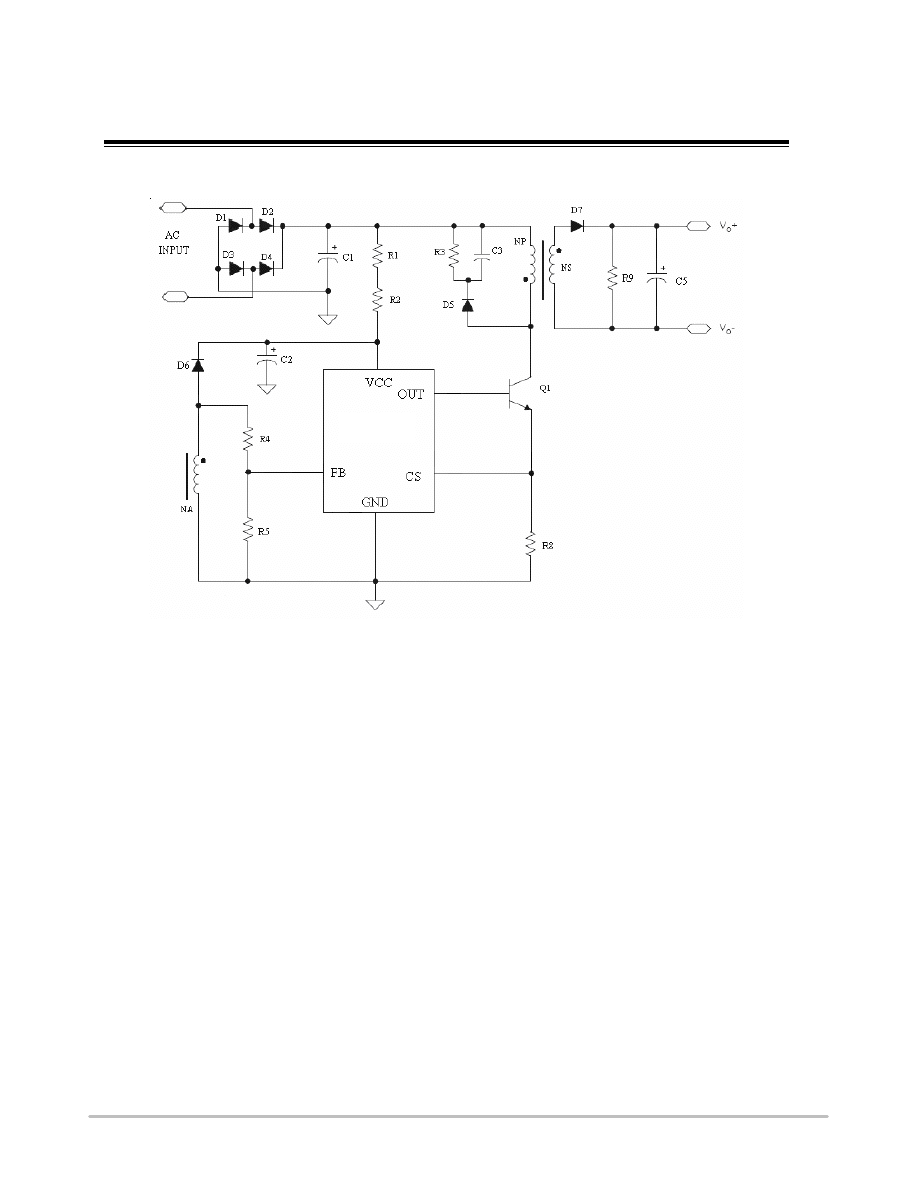
TYPICAL APPLICATION CIRCUIT
Figure 1: Typical Application Circuit
ABSOLUTE MAXIMUM RATINGS
FB to GND………………………………...…………………………………….…….……….….... -0.3V to +9V
CS to GND…………………………………………...……………………………………….…….....-0.3V to +9V
VCC to GND…………………………………..………….…………………………………………-0.3V to +18V
OUT to GND…………………………………...…………………………….……….…………......-0.3V to +9V
Operating Temperature Range……………………...……………………………………………...-40℃ to +125℃
Junction Temperature………………………………..………………………………………….... -40℃ to +150℃
Storage Temperature Range ……………………………..…………………………………….….-60℃ to +150℃
ESD Protection HBM……………….....…………………………………………………………………….2000V
MM…………………..……………………………………………………………………...500V
Stresses exceeding Maximum Ratings may damage the device. Maximum Ratings are stress ratings only.
Functional operation above the Recommended Operating Conditions is not implied. Extended exposure to
stresses above the Recommended Operating Conditions may affect device reliability
.
ART3653A
ART3653A
SEMICONDUCTOR
ARTCHIP
©
3
@ Artchip Semiconductor , 2008
V1.3 2011
ARTCHIP
SEMICONDUCTOR
ART3653A
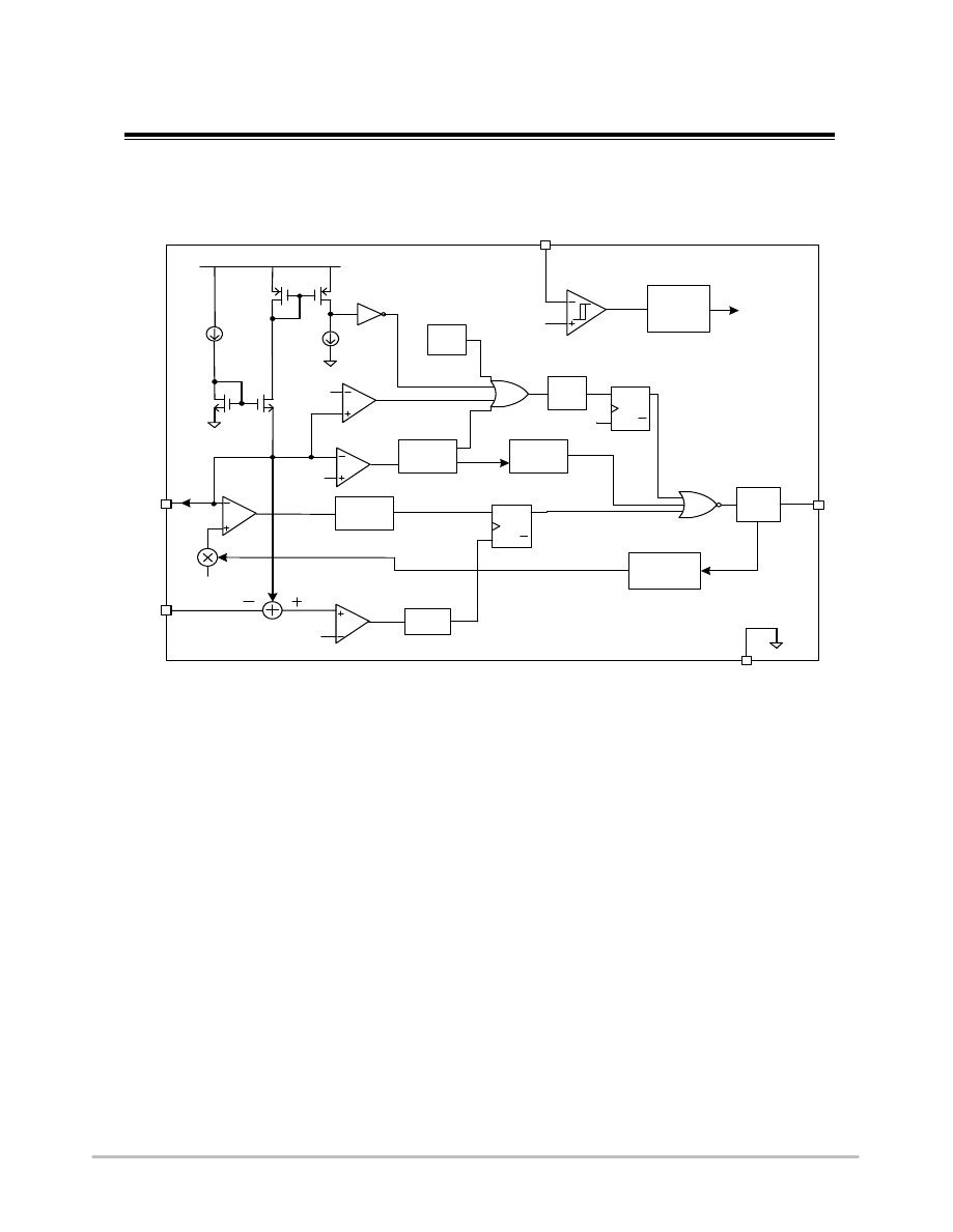
BLOCK DIAGRAM
D river
Q
Q
SET
CLR
S
R
CV
C ontroller
C OM P
0.5V
LEB
400ns
C C
C ontroller
EA
3V
CC M
Protection
V D D
COM P
4.65V
Q
Q
SET
CLR
S
R
PO R
D elay
3uS
Band G ap
LD O
R ef
Internal
reference
& bias
Cable
Com pensation
POR
GND
OUT
CS
FB
VCC
UV LO
O TP
150uA
12.1/5.1V
COM P
0.1V
3 x (1+K cab)V
V line
Vcc_on/Vcc_off
FB_open
Ovp
V cs
V ovp
V fb
Ifb_open
O TP
Ifb
Ibias
V cp
Figure 4: ART3653A Block Diagram
©
4
@ Artchip Semiconductor , 2008
V1.3 2011
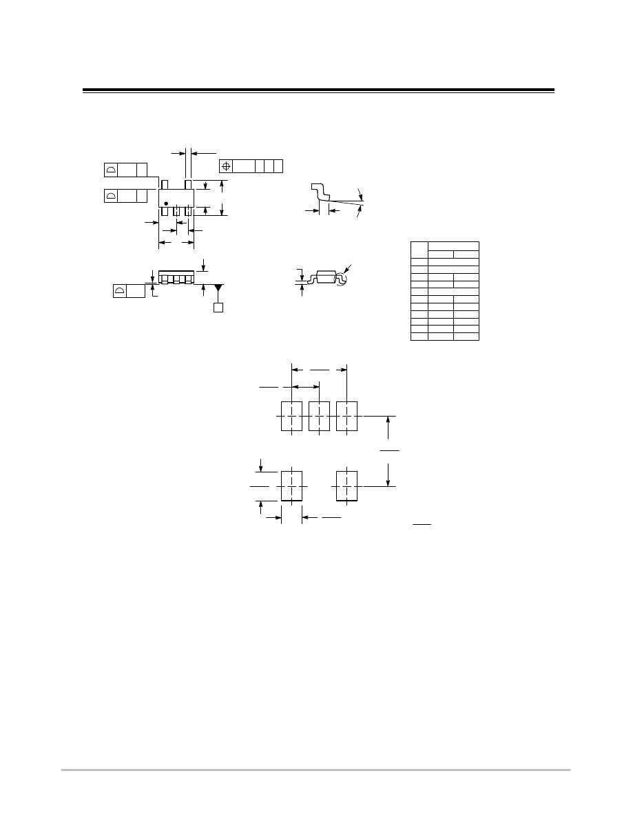
NOTES:
1. DIMENSIONING AND TOLERANCING PER
ASME Y14.5M, 1994.
2. CONTROLLING DIMENSION: MILLIMETERS.
3. MAXIMUM LEAD THICKNESS INCLUDES
LEAD FINISH THICKNESS. MINIMUM LEAD
THICKNESS IS THE MINIMUM THICKNESS
OF BASE MATERIAL.
4. DIMENSIONS A AND B DO NOT INCLUDE
MOLD FLASH, PROTRUSIONS, OR GATE
BURRS.
5. OPTIONAL CONSTRUCTION: AN
ADDITIONAL TRIMMED LEAD IS ALLOWED
IN THIS LOCATION. TRIMMED LEAD NOT TO
EXTEND MORE THAN 0.2 FROM BODY.
DIM
MIN
MAX
MILLIMETERS
A
3.00 BSC
B
1.50 BSC
C
0.90
1.10
D
0.25
0.50
G
0.95 BSC
H
0.01
0.10
J
0.10
0.26
K
0.20
0.60
L
1.25
1.55
M
0
10
S
2.50
3.00
1
2
3
5
4
S
A
G
L
B
D
H
C
J
_
_
0.7
0.028
1.0
0.039
ǒ
mm
inches
Ǔ
SCALE 10:1
0.95
0.037
2.4
0.094
1.9
0.074
SOLDERING FOOTPRINT*
0.20
5X
C A B
T
0.10
2X
2X
T
0.20
T
SEATING
PLANE
0.05
K
M
DETAIL Z
DETAIL Z
ARTCHIP
SEMICONDUCTOR
ART3653A
PACKAGE INFORMATION
©
5
@ Artchip Semiconductor , 2008
V1.3 2011
Wyszukiwarka
Podobne podstrony:
led driver3626
High Efficiency 12V White Led Driver
HV9910B LED DRIVER
AMC7150 ReferenceDesign LED DRIVER
Diody prostownicze, stabilizacyjne, LED
Oswietlenie LED do akwarium id Nieznany
Kolejny miernik na ICL7107 i wyświetlaczach LED wspólna anoda schemat
30 LED Projects
drivers data tab 1
Embedded Linux Kernel And Drivers
21 Montaż oświetlenia LED przestrzeni stóp
Constant current driving of the RGB LED
alpa led 4 kk EMM7XJKOQ7YNP6ZMH Nieznany
6Ż52P driver
Wyposażenie SHARANA w LED
iody led sprawko
Diody LED
How to install HD Audio driver?ter installation of slipstreamed XP SP3
sprawko led
więcej podobnych podstron