13 11
23
19
2
2
5 3 4
20
10
19
17
18
21
22
17
18
8
9
AD91368
all models
&
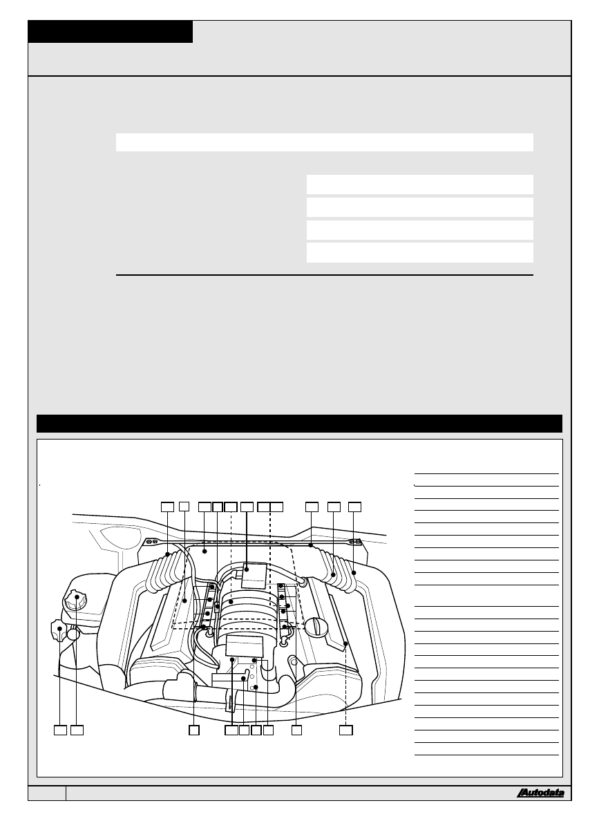
1 Engine control module (ECM) ± above pedals
&
2 Injectors
&
3 Throttle body
&
4 Throttle position (TP) sensor
&
5 Idle air control (IAC) valve
&
6 Fuel pump ± in tank
&
7 Fuel filter ± tank exterior
&
8 Fuel pressure regulator
&
9 Engine coolant temperature (ECT) sensor
&
10 Mass air flow (MAF) sensor
&
11 Evaporative emission canister purge
(EVAP) valve
&
12 Heated Oxygen sensor (HO2S) ± front pipes
&
13 Auxiliary starting terminal
&
14 Fuel pump relay I ± RH kick panel
&
15 Fuel pump relay II ± RH footwell relay plate
&
16 Data link connector (DLC) ± LH fascia
&
17 Ignition distributors
&
18 Ignition coils/modules
&
19 Knock sensors (KS)
&
20 Engine speed (RPM) sensor
&
21 Crankshaft position (CKP) sensor
&
22 Sensor multi-plugs
&
23 Intake air temperature (IAT) sensor
Model:
Engine code:
Year:
V8 4.2L
ABH
1992-94
System:
Bosch Motronic 2.4.1
Fuel system type:
Multi-port injection, sequential
Ignition system type:
ECM controlled with Hall effect trigger
Trouble shooter:
2
Engine management system layout and components
120
# 1997 Copyright Autodata Limited
Self-diagnosis
General information
l
Engine control module (ECM) incorporates self-
diagnosis function.
l
Malfunction indicator lamp (MIL) will illuminate if certain
faults are recorded.
l
ECM operates in backup mode if sensors fail, to enable
car to be driven to workshop.
l
Trouble codes can be accessed with suitable code
reader. Refer to Self-diagnosis section 2.
Trouble code identification
Trouble code Fault location
0000
No fault found
1111
Engine control module (ECM)
1231
Vehicle speed sensor (VSS)
2111
Engine speed (RPM) sensor
2112
Crankshaft position (CKP) sensor
2113
Camshaft position (CMP) sensor/Hall sensor
2114
Hall sensor not at reference mark
2121
Closed throttle position (CTP) switch
2141
Knock sensors (KS)
2142
Knock sensors (KS)
2143
Knock sensors (KS)
2144
Knock sensors (KS)
2212
Throttle position (TP) sensor
2231
Idle air control (IAC) valve
2232
Mass air flow (MAF) sensor
2234
Engine control module (ECM), voltage supply
too high
2312
Engine coolant temperature (ECT) sensor
2314
Engine/transmission connection
2322
Intake air temperature (IAT) sensor
2324
Engine control module (ECM)
2341
Heated oxygen sensor (HO2S)
2342
Heated oxygen sensor (HO2S)
2411
Exhaust gas recirculation (EGR) system control
2413
Fuel/air mixture incorrect
4312
Exhaust gas recirculation (EGR) solenoid
4334
Oxygen sensor heating
4343
Evaporative emission canister purge (EVAP) valve
4411
Injector valve No.1
4412
Injector valve No.2
4413
Injector valve No.3
4414
Injector valve No.4
4421
Injector valve No.5
4422
Injector valve No.6
4431
Idle air control (IAC) valve
Service adjustments
Preparatory conditions
i
Engine at normal operating temperature.
i
Engine oil temperature min. 85aC.
i
Ignition system in good condition.
i
Air filter installed and in good condition.
i
Automatic transmission in `P'.
i
All auxiliary equipment, including air conditioning,
switched OFF.
i
Radiator fan must not run during checks and
adjustments.
Idle speed
Adjustment
TECHNICAL DATA
Automatic transmission
710-770 rpm
Manual transmission
650-710 rpm
l
Idle speed electronically controlled.
l
No adjustment possible.
l
If idle speed not as specified, check for air leaks in
intake system.
l
Carry out component and electrical tests.
CO level
Adjustment
TECHNICAL DATA
All models
0.5-0.9% ± at emission port
l
CO level electronically controlled.
l
No adjustment possible.
l
If CO level not as specified, check for air leaks in intake
and exhaust systems.
l
Carry out component and electrical tests.
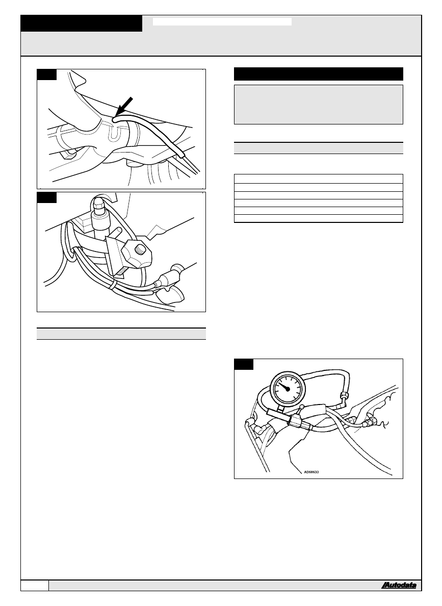
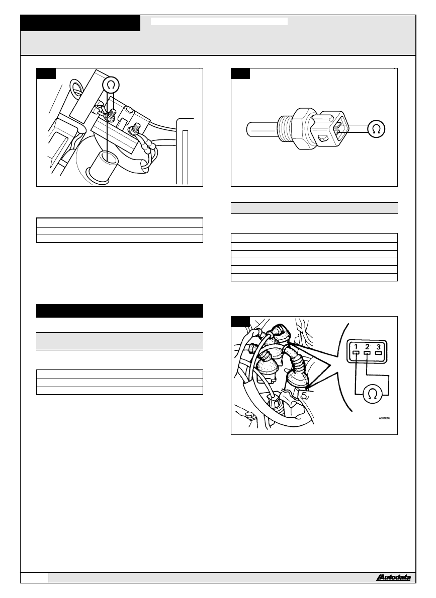
Checking ±
&
1
&
&
2
l
Connect CO meter to CO tap tube
&
1
.
l
Clamp off upper (thicker) carbon canister hose
&
2
.
l
Start engine.
l
Allow to idle.
l
Check CO level.
V8 4.2L
1992-94
AUDI
121
# 1997 Copyright Autodata Limited
1
AD68623
2
AD68624
Throttle initial position
Adjustment
l
Throttle initial position set by manufacturer.
l
No adjustment possible.
Fuel system
CAUTION:
To minimize fire risk, fuel system must be
depressurized before disconnecting any
fuel lines or fuel system components ± refer
to Safety Precautions at the front of this
manual.
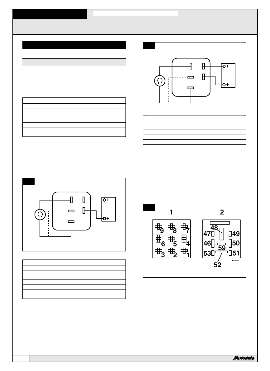
Fuel pressure
Checking ±
&
3
&
&
4
TECHNICAL DATA
Pressure
Condition
Value
System
vacuum OFF
57-61 psi (4-4.3 bar)
Regulated
vacuum ON
48-53 psi (3.4-3.7 bar)
Residual
after 10 minutes (cold)
43 psi (3 bar)
Residual
after 10 minutes (hot)
50 psi (3.5 bar)
l
Ensure ignition switched OFF.
l
Connect pressure gauge between fuel supply pipe and
fuel manifold
&
3
.
l
Remove fuel pump relay I.
l
Jump fuel pump relay base terminal 52 and auxiliary
starting terminal with a switched lead
&
4
.
l
Operate switch to run fuel pump.
l
Check system pressure.
l
Remove jumper lead.
l
Reinstall fuel pump relay I.
l
Start engine.
l
Allow to idle.
l
Compare regulated pressure indicated with that
specified.
l
Switch ignition OFF.
l
After 10 minutes check residual pressure.
3
V8 4.2L
1992-94
122
AUDI
# 1997 Copyright Autodata Limited
4
50
48
47
46
AD68632
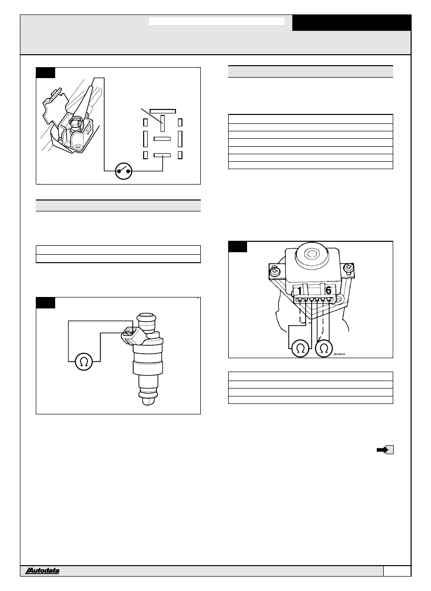
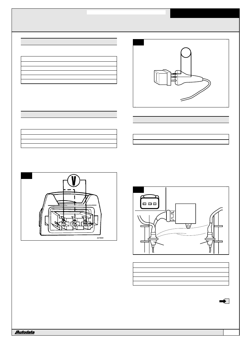
Injectors
Injector spray pattern and leak rate: Refer to General
Test Procedures.
Checking resistance ±
&
5
TECHNICAL DATA
Resistance
15-17 b
l
Ensure ignition switched OFF.
l
Disconnect injector multi-plug.
l
Check resistance between injector multi-plug terminals.
5
AD79117
Throttle position (TP) sensor
NOTE: TP sensor incorporates closed throttle position
(CTP) switch.
Checking ±
&
6
TECHNICAL DATA
Terminals
Accelerator
Resistance
1 & 2
-
1500-2500 b
2 & 3
in idle position
750-1300 b
2 & 3
in full load position
2400-3600 b
4 & 6
in idle position
Zero
4 & 6
partly open
u
l
Ensure ignition switched OFF.
l
Disconnect TP sensor multi-plug.
l
Check resistance between TP sensor terminals 1 and 2.
l
Operate accelerator while checking resistance between
terminals 2 and 3.
l
Resistance change should be smooth.
l
Operate accelerator while checking resistance between
terminals 4 and 6.
6
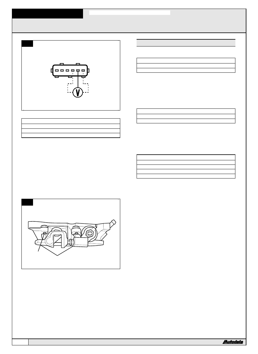
Checking supply voltage ±
&
7
TECHNICAL DATA
Terminals
Voltage
4 & 5
4.5-5.5 V
5 & 6
4.5-5.5 V
l
Ensure ignition switched OFF.
l
Disconnect TP sensor multi-plug.
l
Switch ignition ON.
l
Check voltage between harness multi-plug terminals.
V8 4.2L
1992-94
AUDI
123
# 1997 Copyright Autodata Limited
7
3
2
1
6
5
4
AD74867
Adjustment ±
&
8
TECHNICAL DATA
Terminals Condition
Resistance
4 & 6
0.010 in. (0.25 mm) feeler gauge inserted Zero
4 & 6
0.012 in. (0.30 mm) feeler gauge inserted u
l
Ensure ignition switched OFF.
l
Remove throttle housing.
l
Loosen TP sensor screws.
l
Insert feeler gauge of specified thickness between
throttle lever and stop screw [
1
].
l
Turn TP sensor body counter-clockwise against stop.
l
Turn TP sensor slowly clockwise until resistance
between terminals 4 & 6 as specified.
l
Tighten TP sensor screws.
l
Insert feeler gauge of specified thickness between
throttle lever and stop screw [
1
].
l
Check resistance between terminals 4 & 6.
8
1
AD68629
Mass air flow (MAF) sensor
Checking supply voltage ±
&
7
TECHNICAL DATA
Terminals
Voltage
5 & ground
Battery voltage
l
Ensure ignition switched OFF.
l
Disconnect MAF sensor multi-plug.
l
Switch ignition ON.
l
Check voltage between harness multi-plug terminal and
ground.
Checking ground connection ±
&
7
TECHNICAL DATA
Terminals
Resistance
1 & ground
Zero
l
Ensure ignition switched OFF.
l
Disconnect MAF sensor multi-plug.
l
Check resistance between harness multi-plug terminal
and ground.
Checking voltage ±
&
9
TECHNICAL DATA
Terminals
Condition
Voltage
1 & 3
ignition ON
1.3-1.6 V
1 & 3
engine idling
2.5 V approx.
1 & 3
engine speed raised
3-5 V
l
Ensure ignition switched OFF.
l
Expose MAF sensor multi-plug terminals without
disconnecting multi-plug.
l
Switch ignition ON.
l
Check voltage between multi-plug terminals.
l
Start engine.
l
Allow to idle.
l
Check voltage between multi-plug terminals.
l
Briefly increase rpm.
l
Check voltage between multi-plug terminals.
V8 4.2L
1992-94
124
AUDI
# 1997 Copyright Autodata Limited
9
AD68631
6
1
Checking filament burn off ±
&
9
l
Ensure ignition switched OFF.
l
Engine at normal operating temperature.
l
Expose MAF sensor multi-plug terminals without
disconnecting multi-plug.
l
Connect LED test lamp between multi-plug terminals 1
and 4.
l
Remove fuse No.27.
l
Connect ammeter between fuse terminals.
l
Start engine.
l
Raise engine speed to above 2000 rpm, for more than
3 seconds.
l
Switch ignition OFF.
l
Check filament burn off.
l
If successful burn off indication:
LED illuminates.
ammeter indicates more than 2 A for approximately 1
second.
burn off occurs approximately 3 seconds after engine
stops.
Intake air temperature (IAT) sensor
Checking resistance ±
&
10
TECHNICAL DATA
Temperature
Resistance
68aF (20aC)
450-550 b
l
Ensure ignition switched OFF.
l
Pull back sensor rubber cover.
l
Remove IAT sensor.
l
Check ambient air temperature.
l
Check resistance between IAT sensor terminals.
10
AD73172
Idle air control (IAC) valve
Checking resistance ±
&
11
TECHNICAL DATA
Resistance
7.5-8.5 b
l
Ensure ignition switched OFF.
l
Disconnect IAC valve multi-plug.
l
Remove the IAC valve.
l
Check for high spots on mating faces [
1
].
l
Check for smooth operation.
l
Check resistance between IAC valve terminals.
11
1
AD74215
Checking signal ±
&
12
l
Ensure ignition switched OFF.
l
Disconnect IAC valve multi-plug.
l
Connect LED test lamp between harness multi-plug
terminals.
l
Switch ignition ON.
l
Briefly crank engine.
l
Check that LED flashes.
V8 4.2L
1992-94
AUDI
125
# 1997 Copyright Autodata Limited
12
1
2
AD86786
LED
Ignition system
CAUTION:
To prevent engine starting and to avoid
damaging catalytic converter, disconnect
fuel injector valve multi-plug before
cranking tests ± refer to Safety Precautions
at the front of this manual.
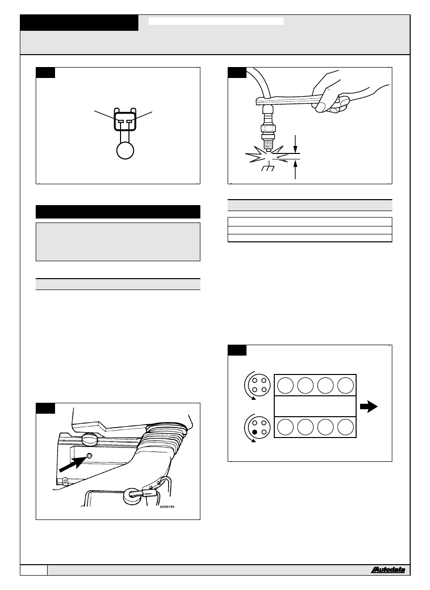
High-tension spark
Checking ±
&
13
&
&
14
l
Ensure ignition switched OFF.
l
Remove upper engine cover
&
13
.
l
Disconnect one high-tension lead from spark plug.
l
Connect test spark plug to high-tension lead.
l
Using insulated pliers, hold test spark plug at 1/4 in.
from suitable ground
&
14
.
l
Briefly crank engine.
l
Check for strong blue spark.
l
Repeat test for each high-tension lead.
l
If no spark is visible, carry out high-tension circuit
component checks.
l
Refer to General Test Procedures.
13
14
AD73908
Ignition timing & firing order
TECHNICAL DATA
Firing order
1-5-4-8-6-3-7-2
Distributor rotation
Counter-clockwise
l
Ignition timing electronically controlled.
l
No adjustment possible.
Checking ±
&
15
,
&
16
&
&
17
l
Ensure ignition switched OFF.
l
Check distributor rotor rotation and firing order
&
15
.
l
Ensure high-tension leads are connected correctly
&
16
.
l
Align crankshaft pulley TDC marks
&
17
[
1
].
l
Rotor arms should align with slots in distributor
housings
&
17
[
2
].
NOTE: If rotor arms not aligned turn crankshaft one
further turn clockwise and recheck.
15
4
3
2
1
6
5
7
8
AD75117
V8 4.2L
1992-94
126
AUDI
# 1997 Copyright Autodata Limited
16
4
3
2
1
6
5
7
8
AD73929
17
O
T
1
2
AD73930
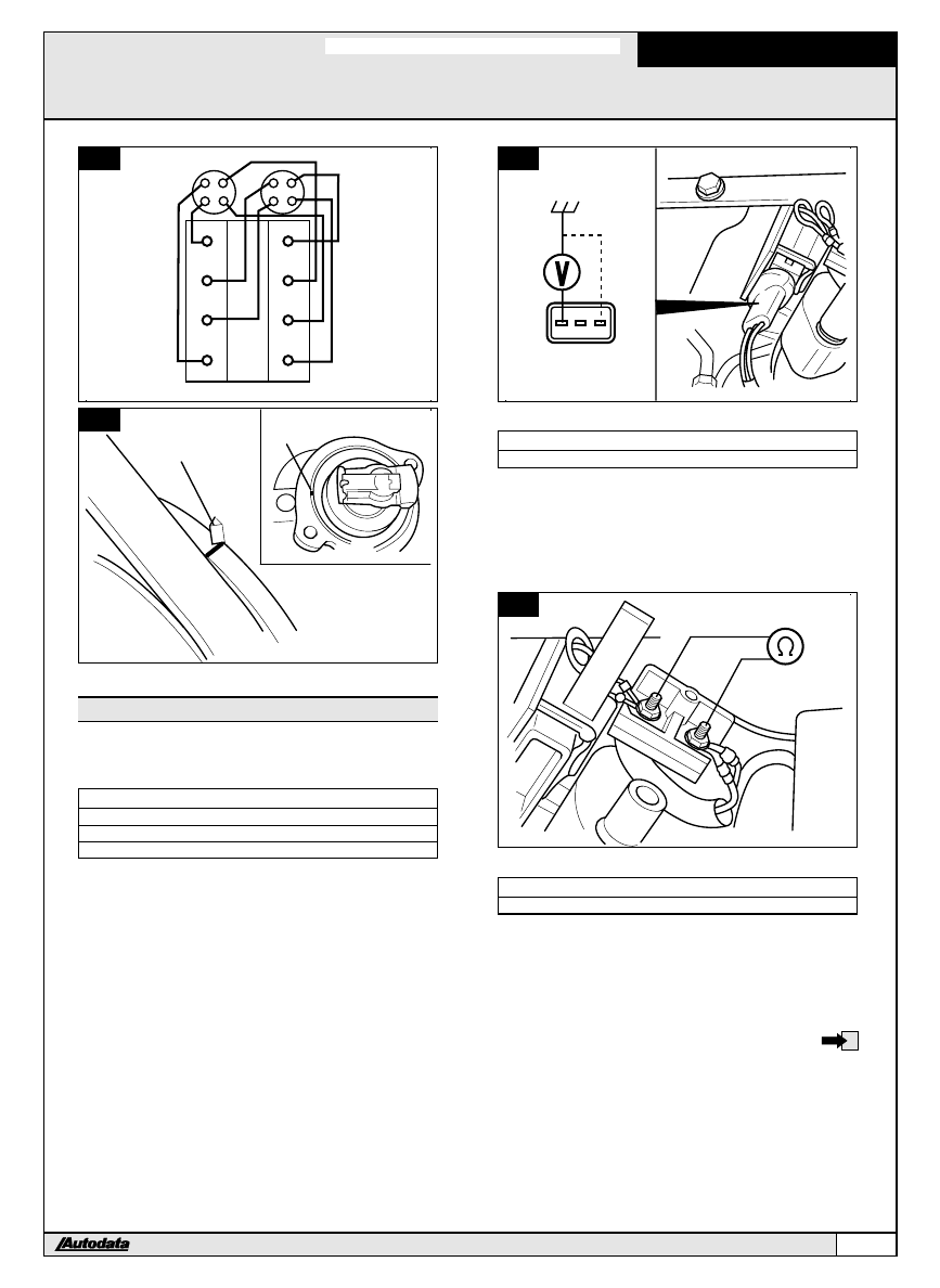
Ignition coil
NOTE: Ignition coil incorporates module.
Checking supply voltage ±
&
18
TECHNICAL DATA
Terminals
Ignition
Voltage
1 & ground
ON
Battery voltage
1 & 3
ON
Battery voltage
l
Ensure ignition switched OFF.
l
Disconnect ignition coil multi-plug.
l
Switch ignition ON.
l
Check voltage between harness multi-plug terminal and
ground.
l
Check voltage between harness multi-plug terminals.
l
Repeat test on other ignition coil.
l
If voltage not as specified, check wiring.
18
1
2 3
AD73931
Checking primary resistance ±
&
19
TECHNICAL DATA
Primary resistance
0.5-1 b
l
Ensure ignition switched OFF.
l
Open cover of low-tension terminals.
l
Disconnect ignition coil low-tension leads.
l
Check resistance between ignition coil low-tension
terminals.
l
Repeat test on other ignition coil.
19
AD69206
Checking secondary resistance ±
&
20
TECHNICAL DATA
Secondary resistance
5000-9000 b
l
Ensure ignition switched OFF.
l
Open cover of low-tension terminals.
l
Disconnect ignition coil low-tension leads.
l
Disconnect ignition coil king lead.
l
Check resistance between one ignition coil low-tension
terminal and the high-tension connection.
l
Repeat test on other ignition coil.
V8 4.2L
1992-94
AUDI
127
# 1997 Copyright Autodata Limited
20
AD69207
Checking signal ±
&
18
NOTE: Disconnect injector multi-plugs before cranking
tests,
TECHNICAL DATA
Terminals
Voltage
2 & 3
0.2 V minimum
l
Ensure ignition switched OFF.
l
Disconnect ignition coil/module multi-plug.
l
Briefly crank engine.
l
Check voltage between harness multi-plug terminals.
Engine sensors
Engine coolant temperature (ECT)
sensor
Checking ±
&
21
TECHNICAL DATA
Temperature
Resistance
68aF (20aC)
1500-3000 b
l
Ensure ignition switched OFF.
l
Disconnect ECT sensor multi-plug.
l
Remove ECT sensor from engine.
l
Check resistance between ECT sensor terminals.
l
ECT sensor may be checked in position if engine
temperature and resistance readings are compared.
21
AD52755
Crankshaft position (CKP) sensor
Checking resistance ±
&
22
TECHNICAL DATA
Multi-plug color
black
Terminals
Resistance
1 & 2
1000 b
1 & 3
u
2 & 3
u
l
Ensure ignition switched OFF.
l
Disconnect CKP sensor multi-plug.
l
Check resistance between CKP sensor terminals.
22
V8 4.2L
1992-94
128
AUDI
# 1997 Copyright Autodata Limited
Engine speed (RPM) sensor
Checking resistance ±
&
22
TECHNICAL DATA
Multi-plug color
gray
Terminals
Resistance
1 & 2
1000 b
1 & 3
u
2 & 3
u
l
Ensure ignition switched OFF.
l
Disconnect CKP sensor multi-plug.
l
Check resistance between CKP sensor terminals.
Camshaft position (CMP) sensor
Checking supply voltage ±
&
23
TECHNICAL DATA
Terminals
Voltage
1 & 3
4.5-5.5 V
2 & 3
4.3-5.2 V
l
Ensure ignition switched OFF.
l
Disconnect distributor multi-plug.
l
Switch ignition ON.
l
Check voltage between harness multi-plug terminals.
23
Checking signal ±
&
24
NOTE: Disconnect injector multi-plugs before cranking
tests, to avoid damage to catalytic converter(s).
l
Ensure ignition switched OFF.
l
Disconnect both module multi-plugs.
l
Expose CMP sensor multi-plug terminals without
disconnecting multi-plug.
l
Connect LED test lamp between multi-plug terminals 1
and 2.
l
Briefly crank engine.
l
Check that LED flashes.
24
LED
1
2
3
AD74065
Knock sensor (KS)
Checking ±
&
25
TECHNICAL DATA
Tightening torque
15 ft. lbs (20 Nm)
l
Ensure ignition switched OFF.
l
Disconnect KS multi-plugs [
1
] & [
2
].
l
Remove KS.
l
Ensure cylinder block and KS mating faces are free
from corrosion and clean.
l
Reinstall KS.
l
Tighten bolt to specified tightening torque.
l
Check each KS.
25
1
2 3
AD73936
1
2
Checking resistance ±
&
25
TECHNICAL DATA
Terminals
Resistance
1 & 2
u
1 & 3
u
2 & 3
u
l
Ensure ignition switched OFF.
l
Disconnect KS multi-plugs [
1
] & [
2
].
l
Check resistance between KS terminals.
V8 4.2L
1992-94
AUDI
129
# 1997 Copyright Autodata Limited
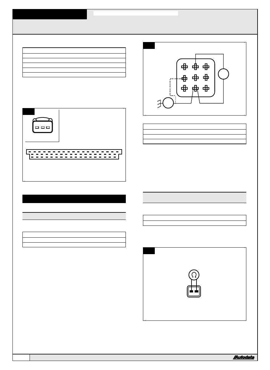
Checking wiring ±
&
26
TECHNICAL DATA
Sensor terminal
ECM terminal
Resistance
1 (left)
29
Zero
1 (right)
11
Zero
2
30
Zero
3
19
Zero
l
Ensure ignition switched OFF.
l
Disconnect engine control module (ECM) multi-plug.
l
Check resistance between ECM harness multi-plug
terminals and knock sensor multi-plug terminals.
l
Check each KS.
26
1
2
3
4
5
6
7
8
9
10
11
12
13
15
14
16
17
18
19
20
21
22
23
24
25
35
34
33
32
31
30
29
28
27
26
36
37
55
54
53
52
51
50
49
48
47
46
45
44
43
42
41
40
39
38
AD69209
1
2 3
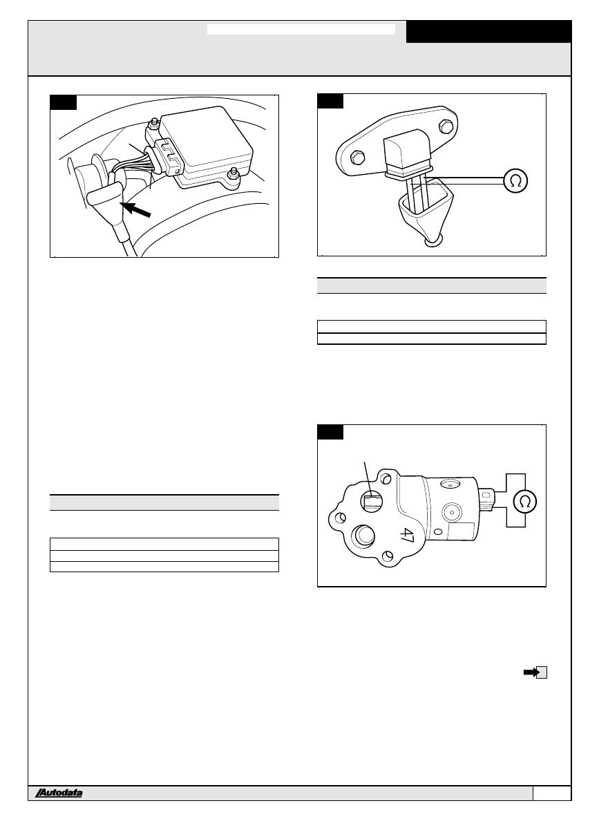
Emission control system
Oxygen sensor heater
Checking heater current ±
&
27
TECHNICAL DATA
Terminals
Current
2 & 8
0.5-4 A
l
Ensure ignition switched OFF.
l
Remove oxygen sensor control unit ± located in RH
footwell.
l
Connect ammeter between control unit base socket
terminals.
l
Switch ignition ON.
l
Check heater current.
27
AD74869
LED
A
1
2
3
4
5
6
7
8
9
Checking signal ±
&
27
TECHNICAL DATA
Terminals
LED
2 & ground
ON
6 & ground
ON
l
Ensure ignition switched OFF.
l
Remove oxygen sensor control unit ± located in RH
footwell.
l
Switch ignition ON.
l
Connect LED test lamp between control unit base
terminals and ground.
l
Check that LED illuminates.
Exhaust gas recirculation (EGR)
solenoid
Checking resistance ±
&
28
TECHNICAL DATA
Resistance
25-35 b
l
Ensure ignition switched OFF.
l
Disconnect EGR solenoid multi-plug.
l
Check resistance between EGR solenoid terminals.
28
AD86047
V8 4.2L
1992-94
130
AUDI
# 1997 Copyright Autodata Limited
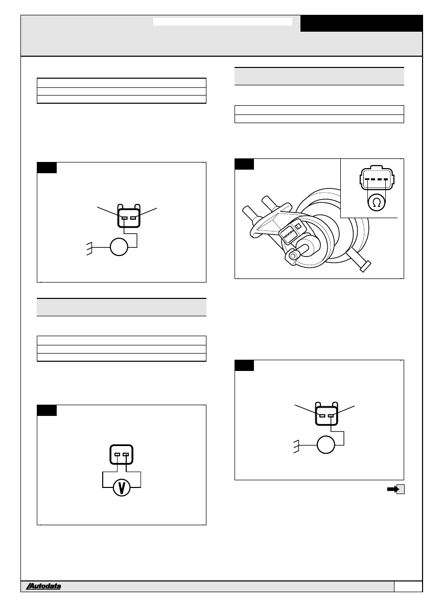
Checking supply voltage ±
&
29
TECHNICAL DATA
Terminals
Condition
LED
1 & ground
engine cranking
ON
l
Ensure ignition switched OFF.
l
Disconnect EGR solenoid multi-plug.
l
Connect LED test lamp between harness multi-plug
terminal and ground.
l
Briefly crank engine.
l
Check that LED illuminates.
29
1
2
AD86805
LED
Exhaust gas recirculation (EGR)
temperature sensor
Checking supply voltage ±
&
30
TECHNICAL DATA
Terminals
Voltage
1 & 2
4.5-5.5 V
l
Ensure ignition switched OFF.
l
Disconnect EGR temperature sensor multi-plug.
l
Switch ignition ON.
l
Check voltage between harness multi-plug terminals.
30
AD74133
Evaporative emission canister purge
(EVAP) valve
Checking resistance ±
&
31
TECHNICAL DATA
Resistance
40-50 b
l
Ensure ignition switched OFF.
l
Disconnect EVAP valve multi-plug.
l
Check resistance between EVAP valve terminals.
31
AD74868
Checking supply ±
&
32
NOTE: Disconnect injector multi-plugs before cranking
tests, to prevent engine from starting.
l
Ensure ignition switched OFF.
l
Disconnect EVAP valve multi-plug.
l
Connect LED test lamp between harness multi-plug
terminal 2 and ground.
l
Briefly crank engine.
l
Check that LED illuminates.
32
1
2
AD86787
LED
V8 4.2L
1992-94
AUDI
131
# 1997 Copyright Autodata Limited
Control system
Fuel pump relay
NOTE: This model is fitted with two fuel pump relays
connected in parallel. Fuel pump relay I ± behind
RH kick panel. Fuel pump relay II ± in RH footwell
fuse/relay plate.
Checking operation ± relay I ±
&
33
TECHNICAL DATA
Terminals
Condition
Resistance
48 & 59
battery voltage disconnected
u
48 & 52
battery voltage disconnected
u
48 & 59
battery voltage connected
Zero
48 & 52
battery voltage connected
Zero
(Battery positive to terminal 46)
(Battery negative to terminal 47)
NOTE: Ensure battery voltage supply connected
correctly, otherwise relay could be damaged.
l
Ensure ignition switched OFF.
l
Remove relay.
l
Check resistance between relay terminals.
l
Connect battery supply to specified relay terminals.
l
Check resistance between relay terminals.
33
AD86788
48
59
52
47
46
Checking operation ± relay II ±
&
34
TECHNICAL DATA
Terminals
Condition
Resistance
2 & 5
battery voltage disconnected
u
2 & 8
battery voltage disconnected
u
2 & 5
battery voltage connected
Zero
2 & 8
battery voltage connected
Zero
(Battery positive to terminal 4)
(Battery negative to terminal 1)
NOTE: Ensure battery voltage supply connected
correctly, otherwise relay could be damaged.
l
Ensure ignition switched OFF.
l
Remove relay.
l
Check resistance between relay terminals.
l
Connect battery supply to specified relay terminals.
l
Check resistance between relay terminals.
34
AD86789
2
5
8
1
4
Checking supply voltage ±
&
35
TECHNICAL DATA
Terminals
Ignition
Voltage
46 & ground
ON
Battery voltage
1 & ground
ON
Battery voltage
l
Ensure ignition switched OFF.
l
Remove fuel pump relay I.
l
Switch ignition ON.
l
Check voltage between relay plate terminals and
ground.
l
Switch ignition OFF.
l
Reinstall fuel pump relay I.
l
Remove fuel pump relay II.
l
Switch ignition ON.
l
Check voltage between relay plate terminals and
ground.
35
V8 4.2L
1992-94
132
AUDI
# 1997 Copyright Autodata Limited
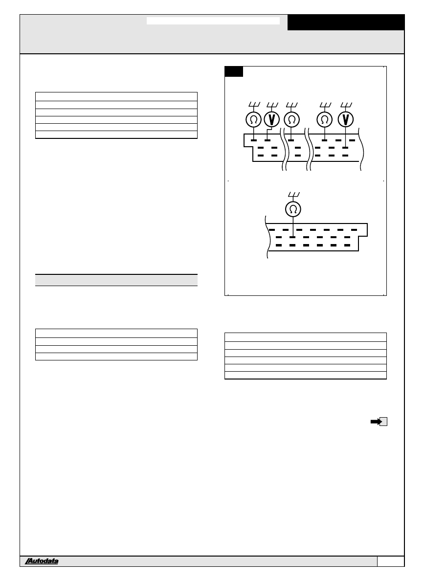
Checking relay activation ±
&
35
NOTE: Disconnect injector multi-plugs before cranking
tests, to avoid damage to catalytic converter(s).
TECHNICAL DATA
Terminals
Condition
LED
46 & 47
ignition ON
ON faintly
46 & 47
engine cranking
ON brightly
1 & 4
ignition ON
ON faintly
1 & 4
engine cranking
ON brightly
l
Ensure ignition switched OFF.
l
Remove fuel pump relays I and II.
l
Connect LED test lamp between relay I base terminals
46 and 47.
l
Switch ignition ON.
l
Check that LED illuminates.
l
Briefly crank engine.
l
Check that LED illuminates.
l
Switch ignition OFF.
l
Connect LED test lamp between relay II base terminals
1 and 4.
l
Switch ignition ON.
l
Check that LED illuminates.
l
Briefly crank engine.
l
Check that LED illuminates.
Engine control module (ECM)
Checking supply voltage ±
&
36
NOTE: Due to small size of engine control module (ECM)
harness multi-plug pins it is advisable to use a
breakout box.
TECHNICAL DATA
Terminals
Ignition
Voltage
18 & ground
OFF
Battery voltage
27 & ground
ON
Battery voltage
l
Ensure ignition switched OFF.
l
Disconnect ECM multi-plug.
l
Connect breakout box to ECM multi-plug.
l
Check voltage between breakout box terminal and
ground.
l
Switch ignition ON.
l
Check voltage between breakout box terminal and
ground.
36
1
2
3
4
5
6
7
8
9
10
11
14
18
19
20
21
22
23
24
25
32
29
28
27
36
37
55
54
50
47
46
45
43
42
41
40
39
38
AD86790
Checking ground connections ±
&
36
NOTE: Due to small size of engine control module (ECM)
harness multi-plug pins it is advisable to use a
breakout box.
TECHNICAL DATA
Terminals
Resistance
10 & ground
Zero
14 & ground
Zero
19 & ground
Zero
24 & ground
Zero
l
Ensure ignition switched OFF.
l
Disconnect ECM multi-plug.
l
Connect breakout box to ECM multi-plug.
l
Check resistance between breakout box terminals
and ground.
V8 4.2L
1992-94
AUDI
133
# 1997 Copyright Autodata Limited
SPINE
LEFT HAND PAGE
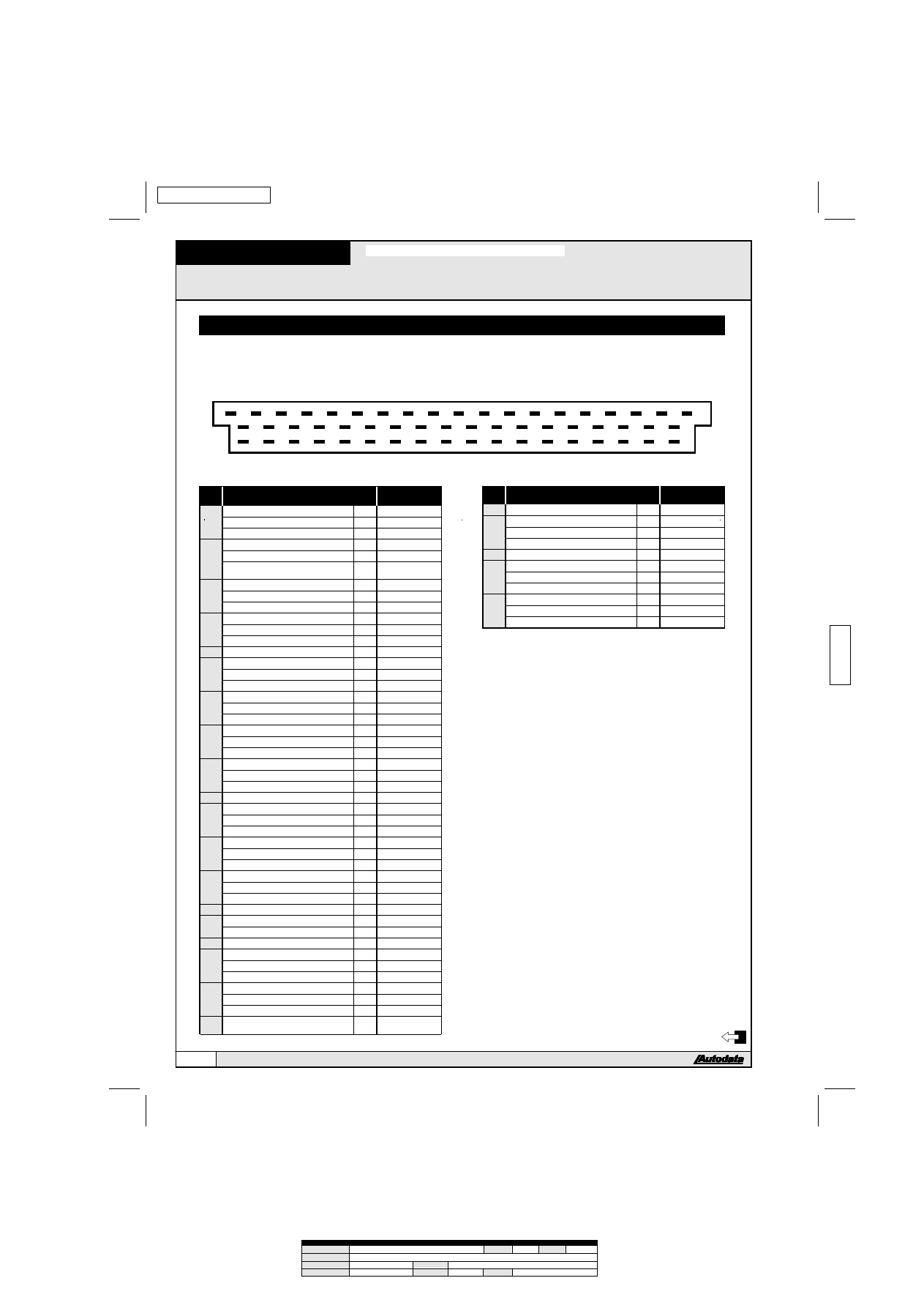
ECM pin diagram
V8 4.2L
1
2
3
4
5
6
7
8
9
10
11
12
13
15
14
16
17
18
19
20
21
22
23
24
25
35
34
33
32
31
30
29
28
27
26
36
37
55
54
53
52
51
50
49
48
47
46
45
44
43
42
41
40
39
38
AD72618
ECM
pin
Component
Comp
Description
p
onent
in no.
Wire color
1
Ignition module No.1
2
green
2
Not used
3
Fuel pump relay
T
brown/green
3
Transmission control module
54
brown/green
4
Idle air control (IAC) valve
2
brown/red
5
Evaporative emission canister purge
(EVAP) valve
1
black/white
6
AC control module
12
green/red
7
Mass air flow (MAF) sensor
3
gray/yellow
8
Camshaft position (CMP) sensor
2
black/violet
9
Spare cable
white/violet
10
Ground
brown/black
11
Knock sensor (KS) No.1
1
brown
12
Camshaft position (CMP) sensor
1
black
13
Data link connector (DLC) No.1
1
white/black
14
Ground
brown
15
Injector valve No.3
1
black/green
16
Injector valve No.8
1
black/gray
17
Injector valve No.5
1
black/violet
18
Battery
+
red/brown
19
Ground
brown/black
20
Ignition module No.2
2
green/black
21
EGR system solenoid
2
brown/yellow
22
Data link connector (DLC) No.1
2
white/black
23
Oxygen sensor control module
86
yellow/blue
24
Ground
brown
25
Mass air flow (MAF) sensor
4
gray
26
Mass air flow (MAF) sensor
2
gray/black
27
Ignition switch
15
black
28
Heated oxygen sensor (HO2S)
29
Knock sensor (KS) No.2
1
brown
30
Ground
black/brown
31
Trip computer
7
green/white
32
Injector valve No.2
1
black/yellow
33
Injector valve No.7
1
black/yellow
34
Injector valve No.6
1
black/green
35
Injector valve No.4
1
black/gray
36
Injector valve No.1
1
black/violet
37
Fuel injection relay
87a red/yellow
38
Spare cable
white/yellow
39
Spare cable
gray/green
40
AC refrigerant pressure switch
green/red
41
AC control module
2
red/black
42
Transmission shift position switch
1
green
43
Not used
44
Intake air temperature (IAT) sensor
white/green
45
Engine coolant temperature (ECT)
sensor
violet
ECM
pin
Component
Comp
Description
p
onent
in no.
Wire color
46
EGR temperature sensor
2
white/red
47
Engine speed (RPM) sensor
2
black
48
Engine speed (RPM) sensor
1
brown
48
Crankshaft position (CKP) sensor
1
brown
49
Crankshaft position (CKP) sensor
2
black
50
Instrumentation control module
white/blue
51
Transmission control module
32
blue/green
52
Throttle position (TP) sensor
1
green/violet
53
Throttle position (TP) sensor
2
blue
54
Transmission control module
47
blue/white
55
Data link connector (DLC) No.2
2
blue/yellow
V8 4.2L
1992-94
Autodata Limited
Copyright 1997
File Name:
aud1
Page no:
134
Version:
X
Path:
g:/pchold1/rack1
Description:
Engine Management US
Comments:
Operator:
Eddie
Job Number:
??????
Date:
28-8-97 (Time: 10:50)
134
AUDI
Document Outline
- Untitled
Wyszukiwarka
Podobne podstrony:
akumulator do audi v8 d11 36 quattro 42 quattro
Audi V8 Star
Audi 200 V8
Audi 200 V8
audi 100 klimaautomatik fehlerspeicher v6 v8 mj1997
akumulator do audi a6 avant 4ac4 42 s6 v8 quattro 42 s6 plus q
akumulator do audi a6 4ac4 42 s6 v8 quattro 42 s6 plus quattro
akumulator do audi 100 avant 4a c4 42 s4 v8 quattro
akumulator do audi 100 4a c4 42 s4 v8 quattro
AUDI COUPE GT 1984
Audi 80 Cabriolet
AllRoadFAQ com Audi C5 2 7T 402 AirLoweringMod[1]
AUDI 100 1990
OPONY - oznaczenia, AUDI 80 B4
Readers v8
kluczyk audi scyzoryk
AUDI A4 8E 2005pl
audi A4 6 stala praca wentylatora chlodnicy
więcej podobnych podstron