
CATIA Kinematics
CATIA® V5R19
Table of Contents, Page i
© Wichita State University
TABLE OF CONTENTS
Introduction . . . . . . . . . . . . . . . . . . . . . . . . . . . . . . . . . . . . . . . . . . . . . . . . . . . . . . . . . . . . . . 1
Fitting Simulation . . . . . . . . . . . . . . . . . . . . . . . . . . . . . . . . . . . . . . . . . . . . . . . . . . . 2
Pull Down Menus . . . . . . . . . . . . . . . . . . . . . . . . . . . . . . . . . . . . . . . . . . . . . . . . . . . 3
Insert . . . . . . . . . . . . . . . . . . . . . . . . . . . . . . . . . . . . . . . . . . . . . . . . . . . . . . . . 3
Tools . . . . . . . . . . . . . . . . . . . . . . . . . . . . . . . . . . . . . . . . . . . . . . . . . . . . . . . 4
Analyze . . . . . . . . . . . . . . . . . . . . . . . . . . . . . . . . . . . . . . . . . . . . . . . . . . . . . 5
Window . . . . . . . . . . . . . . . . . . . . . . . . . . . . . . . . . . . . . . . . . . . . . . . . . . . . . 5
Fitting Simulation Workbench . . . . . . . . . . . . . . . . . . . . . . . . . . . . . . . . . . . . . . . . . . 6
Manipulation . . . . . . . . . . . . . . . . . . . . . . . . . . . . . . . . . . . . . . . . . . . . . . . . . 7
Recorder . . . . . . . . . . . . . . . . . . . . . . . . . . . . . . . . . . . . . . . . . . . . . . . . . . . . . 8
Player . . . . . . . . . . . . . . . . . . . . . . . . . . . . . . . . . . . . . . . . . . . . . . . . . . . . . . . 8
Bottom Toolbar . . . . . . . . . . . . . . . . . . . . . . . . . . . . . . . . . . . . . . . . . . . . . . . . . . . . . 9
Viewing . . . . . . . . . . . . . . . . . . . . . . . . . . . . . . . . . . . . . . . . . . . . . . . . . . . . . 9
Fitting Simulation . . . . . . . . . . . . . . . . . . . . . . . . . . . . . . . . . . . . . . . . . . . . . . . . . . . . . . . . 11
Creating Tracks . . . . . . . . . . . . . . . . . . . . . . . . . . . . . . . . . . . . . . . . . . . . . . . . . . . . 11
Compass . . . . . . . . . . . . . . . . . . . . . . . . . . . . . . . . . . . . . . . . . . . . . . . . . . . . . . . . . . 12
Color Action . . . . . . . . . . . . . . . . . . . . . . . . . . . . . . . . . . . . . . . . . . . . . . . . . . . . . . . 21
Visibility Action . . . . . . . . . . . . . . . . . . . . . . . . . . . . . . . . . . . . . . . . . . . . . . . . . . . . 22
Sequences . . . . . . . . . . . . . . . . . . . . . . . . . . . . . . . . . . . . . . . . . . . . . . . . . . . . . . . . . 23
Shuttles . . . . . . . . . . . . . . . . . . . . . . . . . . . . . . . . . . . . . . . . . . . . . . . . . . . . . 28
Creating a Sequence from Explode . . . . . . . . . . . . . . . . . . . . . . . . . . . . . . . 39
Modifying Tracks . . . . . . . . . . . . . . . . . . . . . . . . . . . . . . . . . . . . . . . . . . . . . . . . . . . 41
Reordering Shots . . . . . . . . . . . . . . . . . . . . . . . . . . . . . . . . . . . . . . . . . . . . . 41
Reusing Shots . . . . . . . . . . . . . . . . . . . . . . . . . . . . . . . . . . . . . . . . . . . . . . . . 43
Shot Time . . . . . . . . . . . . . . . . . . . . . . . . . . . . . . . . . . . . . . . . . . . . . . . . . . . 45
Adding, Deleting and Modifying Shots . . . . . . . . . . . . . . . . . . . . . . . . . . . . 47
Advanced Tracks . . . . . . . . . . . . . . . . . . . . . . . . . . . . . . . . . . . . . . . . . . . . . . . . . . . 49
Mirroring Tracks . . . . . . . . . . . . . . . . . . . . . . . . . . . . . . . . . . . . . . . . . . . . . 50
Reversing Tracks . . . . . . . . . . . . . . . . . . . . . . . . . . . . . . . . . . . . . . . . . . . . . 55
Joining Tracks . . . . . . . . . . . . . . . . . . . . . . . . . . . . . . . . . . . . . . . . . . . . . . . 60
Generating Tracks . . . . . . . . . . . . . . . . . . . . . . . . . . . . . . . . . . . . . . . . . . . . . . . . . . 63
Clash Detection . . . . . . . . . . . . . . . . . . . . . . . . . . . . . . . . . . . . . . . . . . . . . . . . . . . . 64
Path Finder . . . . . . . . . . . . . . . . . . . . . . . . . . . . . . . . . . . . . . . . . . . . . . . . . . . . . . . . 68
Smooth . . . . . . . . . . . . . . . . . . . . . . . . . . . . . . . . . . . . . . . . . . . . . . . . . . . . . . . . . . . 72
Angle Validation . . . . . . . . . . . . . . . . . . . . . . . . . . . . . . . . . . . . . . . . . . . . . . . . . . . 75
Advanced Sequences . . . . . . . . . . . . . . . . . . . . . . . . . . . . . . . . . . . . . . . . . . . . . . . . 79
Advanced Shuttles . . . . . . . . . . . . . . . . . . . . . . . . . . . . . . . . . . . . . . . . . . . . 79
Gantt Chart . . . . . . . . . . . . . . . . . . . . . . . . . . . . . . . . . . . . . . . . . . . . . . . . . . 87
Generating a Replay . . . . . . . . . . . . . . . . . . . . . . . . . . . . . . . . . . . . . . . . . . . 90
Generating a Video . . . . . . . . . . . . . . . . . . . . . . . . . . . . . . . . . . . . . . . . . . . 91
Clash Analysis . . . . . . . . . . . . . . . . . . . . . . . . . . . . . . . . . . . . . . . . . . . . . . . . . . . . . 92
Distance Analysis . . . . . . . . . . . . . . . . . . . . . . . . . . . . . . . . . . . . . . . . . . . . . . . . . . . 99
Analysis with Sequences . . . . . . . . . . . . . . . . . . . . . . . . . . . . . . . . . . . . . . . . . . . . 104
Swept Volumes . . . . . . . . . . . . . . . . . . . . . . . . . . . . . . . . . . . . . . . . . . . . . . . . . . . 108
Experiments . . . . . . . . . . . . . . . . . . . . . . . . . . . . . . . . . . . . . . . . . . . . . . . . . . . . . . 111

CATIA Kinematics
CATIA® V5R19
Table of Contents, Page ii
©Wichita State University
Other Tracks . . . . . . . . . . . . . . . . . . . . . . . . . . . . . . . . . . . . . . . . . . . . . . . . . . . . . . 117
Introduction . . . . . . . . . . . . . . . . . . . . . . . . . . . . . . . . . . . . . . . . . . . . . . . . . . . . . . . . . . . . 119
Kinematics . . . . . . . . . . . . . . . . . . . . . . . . . . . . . . . . . . . . . . . . . . . . . . . . . . . . . . . 120
Pull Down Menus . . . . . . . . . . . . . . . . . . . . . . . . . . . . . . . . . . . . . . . . . . . . . . . . . 121
Insert . . . . . . . . . . . . . . . . . . . . . . . . . . . . . . . . . . . . . . . . . . . . . . . . . . . . . . 121
Tools . . . . . . . . . . . . . . . . . . . . . . . . . . . . . . . . . . . . . . . . . . . . . . . . . . . . . 123
Analyze . . . . . . . . . . . . . . . . . . . . . . . . . . . . . . . . . . . . . . . . . . . . . . . . . . . 124
Window . . . . . . . . . . . . . . . . . . . . . . . . . . . . . . . . . . . . . . . . . . . . . . . . . . . 124
Kinematics Workbench . . . . . . . . . . . . . . . . . . . . . . . . . . . . . . . . . . . . . . . . . . . . . 125
Player . . . . . . . . . . . . . . . . . . . . . . . . . . . . . . . . . . . . . . . . . . . . . . . . . . . . . 126
Bottom Toolbar . . . . . . . . . . . . . . . . . . . . . . . . . . . . . . . . . . . . . . . . . . . . . . . . . . . 127
Viewing . . . . . . . . . . . . . . . . . . . . . . . . . . . . . . . . . . . . . . . . . . . . . . . . . . . 127
Kinematics . . . . . . . . . . . . . . . . . . . . . . . . . . . . . . . . . . . . . . . . . . . . . . . . . . . . . . . . . . . . . 129
Joints . . . . . . . . . . . . . . . . . . . . . . . . . . . . . . . . . . . . . . . . . . . . . . . . . . . . . . . . . . . 129
Revolute - Null Offset . . . . . . . . . . . . . . . . . . . . . . . . . . . . . . . . . . . . . . . . 130
Revolute - Centered . . . . . . . . . . . . . . . . . . . . . . . . . . . . . . . . . . . . . . . . . . 136
Prismatic . . . . . . . . . . . . . . . . . . . . . . . . . . . . . . . . . . . . . . . . . . . . . . . . . . 139
Cylindrical - Angle and Length . . . . . . . . . . . . . . . . . . . . . . . . . . . . . . . . . 142
Cylindrical - Length . . . . . . . . . . . . . . . . . . . . . . . . . . . . . . . . . . . . . . . . . . 145
Cylindrical - Angle . . . . . . . . . . . . . . . . . . . . . . . . . . . . . . . . . . . . . . . . . . . 147
Screw . . . . . . . . . . . . . . . . . . . . . . . . . . . . . . . . . . . . . . . . . . . . . . . . . . . . . 149
Spherical . . . . . . . . . . . . . . . . . . . . . . . . . . . . . . . . . . . . . . . . . . . . . . . . . . 152
Planar . . . . . . . . . . . . . . . . . . . . . . . . . . . . . . . . . . . . . . . . . . . . . . . . . . . . . 154
Rigid . . . . . . . . . . . . . . . . . . . . . . . . . . . . . . . . . . . . . . . . . . . . . . . . . . . . . . 156
Point Curve . . . . . . . . . . . . . . . . . . . . . . . . . . . . . . . . . . . . . . . . . . . . . . . . 158
Slide Curve . . . . . . . . . . . . . . . . . . . . . . . . . . . . . . . . . . . . . . . . . . . . . . . . . 160
Roll Curve . . . . . . . . . . . . . . . . . . . . . . . . . . . . . . . . . . . . . . . . . . . . . . . . . 162
Point Surface . . . . . . . . . . . . . . . . . . . . . . . . . . . . . . . . . . . . . . . . . . . . . . . 165
Universal . . . . . . . . . . . . . . . . . . . . . . . . . . . . . . . . . . . . . . . . . . . . . . . . . . 168
Constant Velocity . . . . . . . . . . . . . . . . . . . . . . . . . . . . . . . . . . . . . . . . . . . . 173
Gear . . . . . . . . . . . . . . . . . . . . . . . . . . . . . . . . . . . . . . . . . . . . . . . . . . . . . . 176
Rack . . . . . . . . . . . . . . . . . . . . . . . . . . . . . . . . . . . . . . . . . . . . . . . . . . . . . . 180
Cable . . . . . . . . . . . . . . . . . . . . . . . . . . . . . . . . . . . . . . . . . . . . . . . . . . . . . 183
Joints using Axis Systems . . . . . . . . . . . . . . . . . . . . . . . . . . . . . . . . . . . . . 185
Assembly Constraints . . . . . . . . . . . . . . . . . . . . . . . . . . . . . . . . . . . . . . . . . . . . . . 189
Auto Create . . . . . . . . . . . . . . . . . . . . . . . . . . . . . . . . . . . . . . . . . . . . . . . . 189
Advanced . . . . . . . . . . . . . . . . . . . . . . . . . . . . . . . . . . . . . . . . . . . . . . . . . . 191
Simulations . . . . . . . . . . . . . . . . . . . . . . . . . . . . . . . . . . . . . . . . . . . . . . . . . . . . . . 197
Simulation . . . . . . . . . . . . . . . . . . . . . . . . . . . . . . . . . . . . . . . . . . . . . . . . . 197
Compiling the simulation . . . . . . . . . . . . . . . . . . . . . . . . . . . . . . . . . . . . . . 200
Replay . . . . . . . . . . . . . . . . . . . . . . . . . . . . . . . . . . . . . . . . . . . . . . . . . . . . 201
Simulation player . . . . . . . . . . . . . . . . . . . . . . . . . . . . . . . . . . . . . . . . . . . . 202
Sequences . . . . . . . . . . . . . . . . . . . . . . . . . . . . . . . . . . . . . . . . . . . . . . . . . . 204
Generate Replay . . . . . . . . . . . . . . . . . . . . . . . . . . . . . . . . . . . . . . . . . . . . . 207
Generate Video . . . . . . . . . . . . . . . . . . . . . . . . . . . . . . . . . . . . . . . . . . . . . 208

CATIA Kinematics
CATIA® V5R19
Table of Contents, Page iii
© Wichita State University
Knowledgeware . . . . . . . . . . . . . . . . . . . . . . . . . . . . . . . . . . . . . . . . . . . . . . . . . . . 210
Laws . . . . . . . . . . . . . . . . . . . . . . . . . . . . . . . . . . . . . . . . . . . . . . . . . . . . . . 210
Rules . . . . . . . . . . . . . . . . . . . . . . . . . . . . . . . . . . . . . . . . . . . . . . . . . . . . . 214
Advanced Laws . . . . . . . . . . . . . . . . . . . . . . . . . . . . . . . . . . . . . . . . . . . . . 218
Path Generation . . . . . . . . . . . . . . . . . . . . . . . . . . . . . . . . . . . . . . . . . . . . . . . . . . . 224
Traces . . . . . . . . . . . . . . . . . . . . . . . . . . . . . . . . . . . . . . . . . . . . . . . . . . . . . 224
Swept Volumes . . . . . . . . . . . . . . . . . . . . . . . . . . . . . . . . . . . . . . . . . . . . . 227
Sensors . . . . . . . . . . . . . . . . . . . . . . . . . . . . . . . . . . . . . . . . . . . . . . . . . . . . . . . . . . 233
Speed and Acceleration . . . . . . . . . . . . . . . . . . . . . . . . . . . . . . . . . . . . . . . 239
Clash and Distance . . . . . . . . . . . . . . . . . . . . . . . . . . . . . . . . . . . . . . . . . . . 243
Joint Limits . . . . . . . . . . . . . . . . . . . . . . . . . . . . . . . . . . . . . . . . . . . . . . . . 249
Mechanism Dressup . . . . . . . . . . . . . . . . . . . . . . . . . . . . . . . . . . . . . . . . . . . . . . . . 251
Mechanism Analysis . . . . . . . . . . . . . . . . . . . . . . . . . . . . . . . . . . . . . . . . . . . . . . . 255
Tracks and Simulations . . . . . . . . . . . . . . . . . . . . . . . . . . . . . . . . . . . . . . . . . . . . . 257
Problems . . . . . . . . . . . . . . . . . . . . . . . . . . . . . . . . . . . . . . . . . . . . . . . . . . . . . . . . . . . . . . 259
Problem #1 . . . . . . . . . . . . . . . . . . . . . . . . . . . . . . . . . . . . . . . . . . . . . . . . . . . . . . . 259
Problem #2 . . . . . . . . . . . . . . . . . . . . . . . . . . . . . . . . . . . . . . . . . . . . . . . . . . . . . . . 260
Problem #3 . . . . . . . . . . . . . . . . . . . . . . . . . . . . . . . . . . . . . . . . . . . . . . . . . . . . . . . 261
Problem #4 . . . . . . . . . . . . . . . . . . . . . . . . . . . . . . . . . . . . . . . . . . . . . . . . . . . . . . . 262
Problem #5 . . . . . . . . . . . . . . . . . . . . . . . . . . . . . . . . . . . . . . . . . . . . . . . . . . . . . . . 263
Problem #6 . . . . . . . . . . . . . . . . . . . . . . . . . . . . . . . . . . . . . . . . . . . . . . . . . . . . . . . 264
Appendix A . . . . . . . . . . . . . . . . . . . . . . . . . . . . . . . . . . . . . . . . . . . . . . . . . . . . . . . . . . . . 267
Digital Mockup - DMU Fitting - DMU Fitting . . . . . . . . . . . . . . . . . . . . . . . . . . . 267
Digital Mockup - DMU Fitting - DMU Manipulation . . . . . . . . . . . . . . . . . . . . . . 268

CATIA Fitting Simulation
CATIA® V5R19
Fitting Simulation - Introduction, Page 1
© Wichita State University
Introduction
CATIA Version 5 Fitting Simulation
Upon completion of this course the student should have a full understanding of the
following topics:
-
Creating tracks
-
Editing Sequences
-
Creating replays and playing them back
-
Using pathfinder to determine a path
-
Performing clash analysis during a fitting simulation

CATIA Fitting Simulation
CATIA® V5R19
Fitting Simulation - Introduction, Page 2
©Wichita State University
Fitting Simulation
Fitting simulation often gets confused with kinematics because it involves motion. The
main difference between a fitting simulation and a kinematic simulation is that a fitting
simulation moves according to a set path without regard to constraints. A kinematic
simulation moves according to defined joints which control the motion of an assembly.
The purpose of fitting simulation is to show how to assemble or disassemble an assembly.
This can be useful to create training videos or just to make sure that it is possible to
disassemble or assemble an assembly in the defined space. The analysis available in
Assembly Design only allows you to perform a clash analysis between objects in their static
state. In Fitting Simulation, you can perform clash analysis between the objects as they are
being disassembled or assembled. Kinematics can perform a clash analysis as an assembly
operates.
Since Fitting Simulation does not involve constraints, assembly constraints are unnecessary
to perform a simulation. However, you normally would want to constrain your assembly in
order to have all of the parts located correctly.

CATIA Kinematics
CATIA® V5R19
Kinematics - Introduction, Page 119
© Wichita State University
Introduction
CATIA Version 5 Kinematics
Upon completion of this course the student should have a full understanding of the
following topics:
-
Creating joints
-
Creating simulations and replays
-
Performing analysis on a kinematic mechanism
-
Using laws to help simulate a mechanism
-
Converting assembly constraints to joints

CATIA Kinematics
CATIA® V5R19
Kinematics - Introduction, Page 120
©Wichita State University
Kinematics
The first item that needs to be understood is what is kinematics. Kinematics involves an
assembly of parts that are connected together by a series of joints, referred to as a
mechanism. These joints define how an assembly can perform motion. When one of the
joints move it causes the assembly to move. Kinematics does not involve any type of finite
element analysis which means there are no associated loads or weights with the parts. You
are simply moving the assembly through some range of motion as defined by the joints.
Sometimes kinematics gets confused with animation as well. Although kinematics does
perform some actions similar to animation, it is a very limited. Kinematics is meant to
show the range of motion of a mechanical mechanism. Basically, it will show how the
movement of one joint affects all of the other joints defined in the mechanism.
The second item that needs to be understood are degrees of freedom. Every part has six
degrees of freedom. It can move in three directions and it can also rotate about those three
directions. In order for an assembly to be used in kinematics it must have at least one
degree of freedom. The remaining degrees of freedom are controlled with commands. This
is what allows the motion of the mechanism to be defined.
The hardest part about kinematics is figuring out what joints need to be defined on an
assembly in order for it to operate correctly. The actual definition of the joints is pretty
easy. Kinematics requires you to think a little differently without letting finite element
analysis and animation to confuse the situation.
Kinematics is used to check for clearances and interferences among moving parts, and
analyze the velocities of parts as well. In addition, laws can be applied to the mechanism to
force the parts to accelerate.

CATIA Kinematics
CATIA® V5R19
Kinematics - Simulations, Page 197
© Wichita State University
Simulations
Up until now you have been simulating your mechanisms using the simulation with
commands icon. You can also create a simulation that can be used to generate a replay or a
movie file for external use. The simulation can be used in conjunction with sequences that
will allow you to put multiple simulations together and vary their duration.
Simulation
This will allow you to create a simulation that can be used to make a replay or movie file.
In addition, simulations can be put together in a sequence.
Open the Simulation - Replay document located in the Simulation directory. A
simple cam mechanism appears. The mechanism is already constrained with an angle
command that drives the assembly. Instead of using the simulation with commands icon
you are going to create a simulation.
Select the Simulation icon.
A Select window appears. This will show all of the
available simulation objects in your document.
Select the Cam object from the window and select OK. Two windows appear. One of
them is the Kinematics Simulation window which is similar to the window that appears with
the simulation with commands icon.
Check Joint Limits
Checks to see if any joint limits are being reached
Keep position on exit The current position of your mechanism will remain when exiting the
simulation. Otherwise it will reset to its original position.
CATIA Kinematics
CATIA® V5R19
Kinematics - Simulations, Page 198
©Wichita State University
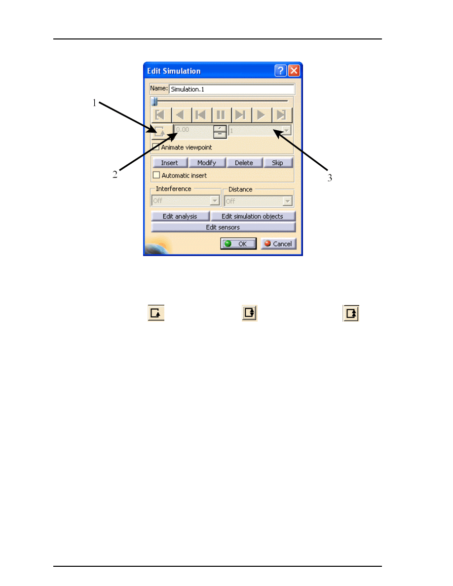
The second window is the Edit Simulation window.
Name
Defines a name for the simulation. Each simulation should be given a
unique and descriptive name for future reference.
Arrow 1
The loop mode icon. Selecting this icon will change the loop mode between
single loop
, forward and reverse
, or continuous forward
.
Arrow 2
The time step indicator. Each motion placed in the simulation indicates a
time step and is displayed in the box.
Arrow 3
The replay interpolation step. In general, it controls the speed of the replay.
Animate viewpoint
Allows the viewpoint position to be recorded with the
simulation. This would be useful if a certain area needs
special attention while a component is being removed.
Insert, Modify, Delete, Skip
Allows you to insert steps manually, modify the position at a
desired step, delete a step or skip over a step during replay
Automatic insert
Allows the positions to be automatically inserted
Edit analysis
Allows you to add or remove various analyses to your
simulation
Edit simulation objects
Allows you to add additional objects that you want to be part
of the simulation
Edit sensors
Allows you to turn on sensors to be observed

CATIA Kinematics
CATIA® V5R19
Kinematics - Simulations, Page 199
© Wichita State University
Change the Name to be Cam mechanism. You have to be careful when inserting steps if
you want a uniform speed. The best way to insert steps at a uniform speed is to change the
command value using the step arrows.
Select the Browse icon in the Kinematics Simulation window and change the Spin box
increments to 5.0 and select OK.
You are going to insert a step into the simulation
every 5 degrees.
Select the Automatic insert option in the Edit Simulation window. This will insert a step
every time you change the command value.
In the Kinematics Simulation window press and hold the first mouse button while on
the up arrow of the command value box. This will change the command value in 5
degree increments until it reaches 360. There should be 72 steps in the simulation.
Select OK in the Edit Simulation window. Both windows close. You should see a
Simulation branch under the Applications branch that contains the simulation.
Double select on the Cam mechanism simulation. The windows reappear.
Select the Jump to Start icon.
The simulation returns to the beginning.
Select the Play Forward icon.
The simulation plays forward.
Change the replay step to 0.2 and change the Loop Mode to Continuos Forward.
Select the Play Forward icon.
Notice that the simulation runs fairly slow and it will
continue to run until you select pause.
Select the Pause icon and select OK.
The simulation stops and the windows close.
Notice that the assembly returned to its original position since you did not turn on the Keep
position on exit option. You are going to create a replay out of this simulation.

CATIA Kinematics
CATIA® V5R19
Kinematics - Simulations, Page 200
©Wichita State University
Compiling the simulation
After a simulation is created, you can generate a replay or a movie file by compiling the
simulation. This will create an external file that can viewed without CATIA or it can create
an internal replay to be used by other users.
Select the Compile Simulation icon.
A Compile Simulation window appears. The
icon is located under the Simulation icon.
Generate a replay
This will compile the simulation into a replay. The replay can
only be viewed from within CATIA V5.
Name
Defines a name for the replay
Generate an animation file
Compiles the simulation into one of three file types
Definition
Allows you to change what simulation will be compiled, the
time step that it will be compiled at (same as the replay
interpolation setting from the Edit Simulation window) and if
the viewpoint is going to be compiled into the animation or
replay
Turn on the Generate a replay option, change the Name to Cam, change the Time step
to 0.2 and select OK. The replay is generated and a Replay branch appears under the
Applications branch. This may take a couple of seconds to compute all of the motion.
CATIA Kinematics
CATIA® V5R19
Kinematics - Simulations, Page 201
© Wichita State University
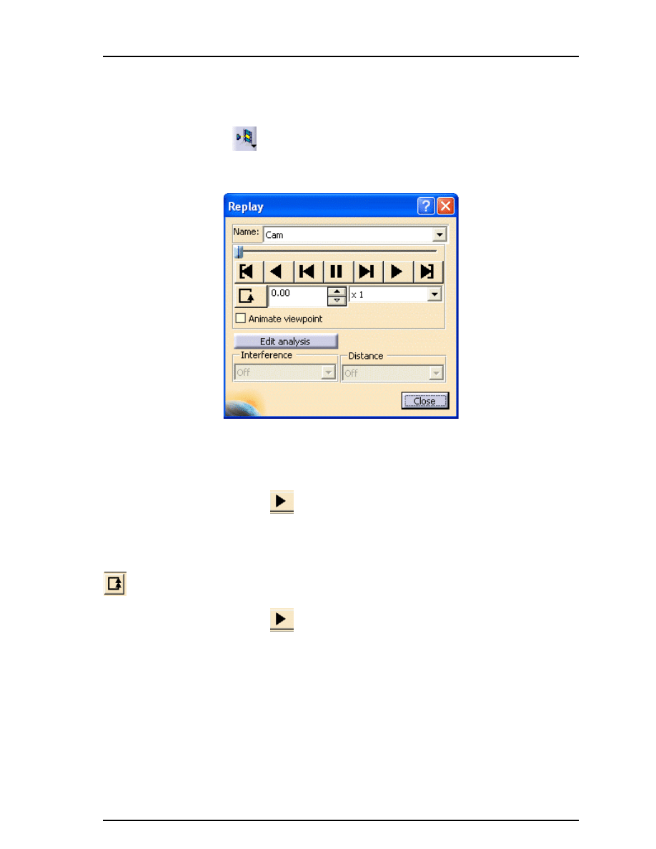
Replay
The replay option allows you to play a replay. This is an easy way to view an internal
replay.
Select the Replay icon.
A Replay window appears. This will allow you to play your
replay. The icon is located under the Simulation or Compile Simulation icon. You can also
get to this window by double selecting on the replay itself.
Most of the icons are the same as on the Edit Simulation window. The one exception is the
replay time step interpolation list is now a replay speed. If the simulation was compiled at
too slow a speed, it can be sped up using this dialog.
Select the Play Forward icon.
Notice that the replay is much smoother than when
you played the simulation. This is because all of the calculations have already been
performed and this is simply a video playback.
Change the Loop Mode to Continuous Forward and change the replay speed to be x2.
This will play the replay over and over again creating a constant moving cam.
Select the Play Forward icon.
The cam mechanism continues to run over and over
again.
Select the Close button. The window closes and the cam returns to its original position.
CATIA Kinematics
CATIA® V5R19
Kinematics - Simulations, Page 202
©Wichita State University
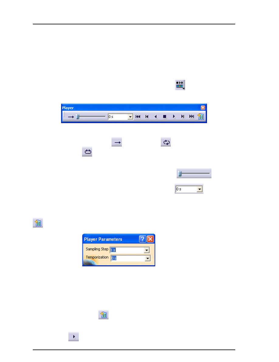
Simulation player
The simulation player is an alternative to using the replay option. You can play any item
that has motion defined. In other words, you can use this player to play a simulation or a
replay. In addition, the player’s speed is adjusted using a time variable. This can be
important if you are using simulations with laws that are set up using time. The player can
also be slowed down or sped up as opposed to the replay option which could only speed up
the replay.
Select the Simulation Player icon and select the Cam replay.
A Player window
appears. This will determine which item will be played.
Change loop mode
Similar to the replay window you can have your item play either one
time forward
, continuous loop
, or forward and backward
.
Simulation line
The slider can be slid along the line to various locations automatically
moving your item to that parameter value.
Parameter value
Shows the current value of the parameter
Player commands
These act very similar to the commands available in the other
windows.
Allows you to modify the parameters of the player
Sampling Step
Defines how fast or slow the player will play
the item
Temporization
Defines how long the player will pause after
each step before continuing
Select the Parameters icon.
The Player Parameters window appears.
Change the Sampling Step to 1.0s and the Temporization to 0.0s and select the Play
Forward icon.
The replay plays quite fast.
CATIA Kinematics
CATIA® V5R19
Kinematics - Simulations, Page 203
© Wichita State University
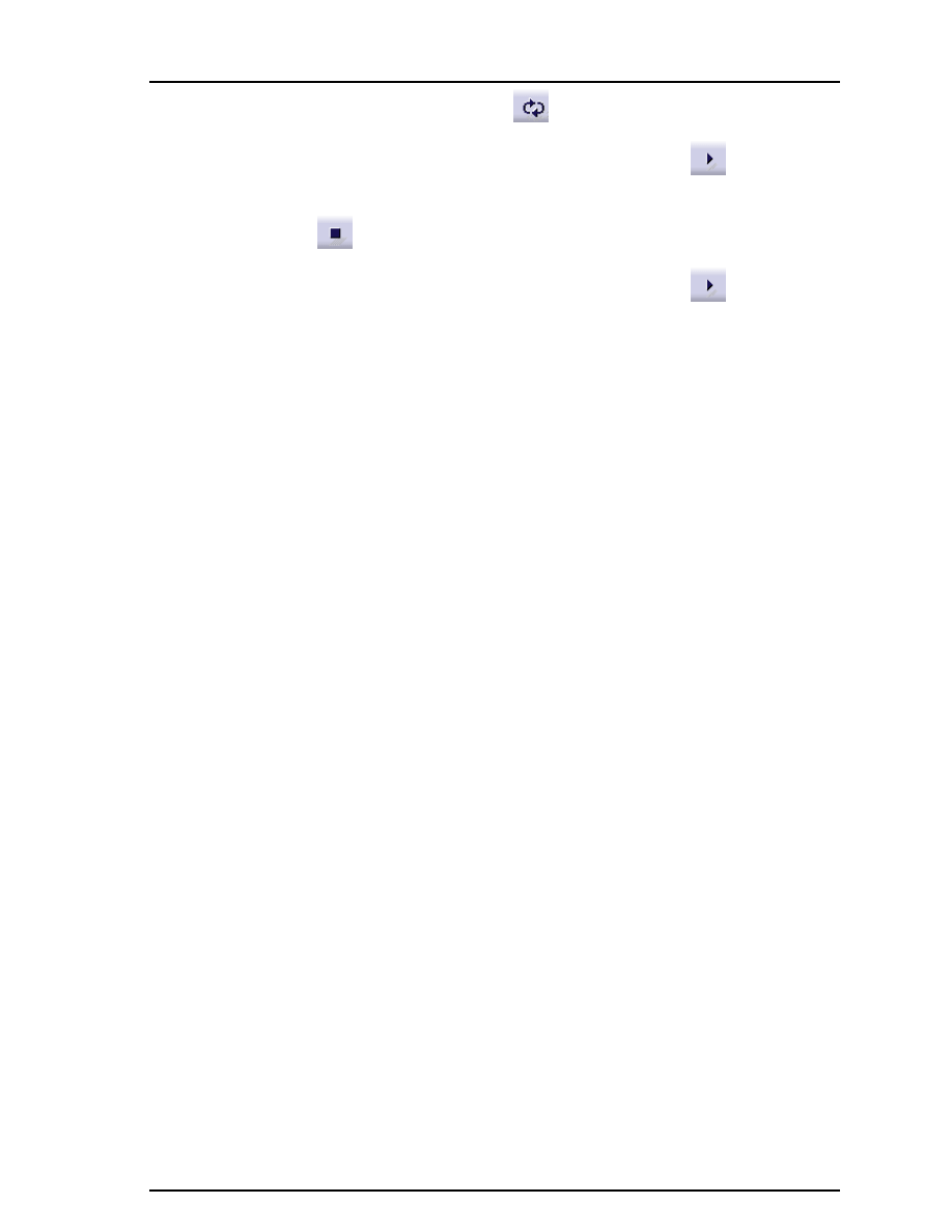
Change the Loop Mode to Continuous Loop.
Change the Sampling Step to 0.5s and select the Play Forward icon.
The replay
plays continuously.
Select the Stop icon.
The replay stops playing.
Change the Temporization to 0.2s and select the Play Forward icon.
Notice that
the replay is playing much slower since it pauses 0.2s each time it takes a step. The motion
will be jerky.
Close the player. You can do this by selecting on the X in the top right corner of the Player
window or by selecting the icon again. The window closes and the assembly returns to its
initial position.
CATIA Kinematics
CATIA® V5R19
Kinematics - Simulations, Page 204
©Wichita State University
Sequences
Sequences allow you to put together a sequence of actions. These actions can be assigned a
duration which determines how fast an action occurs. This allows you to have multiple
actions occur at the same time if desired. This exercise will have you create a sequence
using the one simulation that you created.
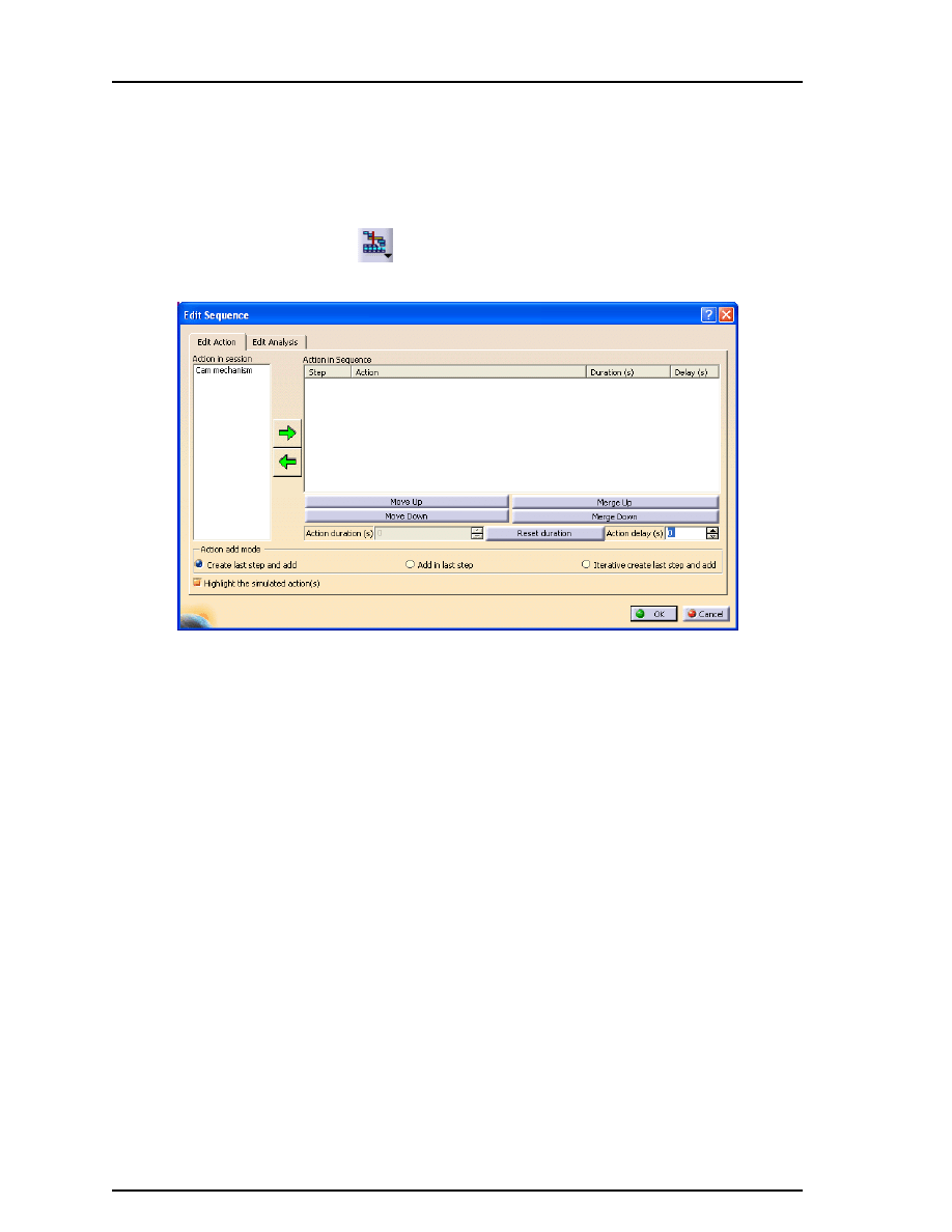
Select the Edit Sequence icon.
The Edit Sequence window appears along with the
Player window. The icon is located under the simulation player icon.
Action in session
These are all the actions that can be added to the sequence.
Action in Sequence
This is where your sequence will appear. By selecting one of the
actions in the session, then selecting the right arrow, the action will
be merged into the sequence.
Move Up/Down
Changes the order of the actions in the sequence
Merge Up/Down
Merges actions together to make them occur at the same time
Action duration
Defines the length of time for each action in seconds
Reset duration
Resets the duration to its original duration
Action delay
Defines how long an action will wait before beginning
Action add mode
Defines how the next action gets added to the sequence
Create last step and add
Adds the next action after the last action (Consecutive)
Add in last step
Adds the next action with the last action
(Simultaneous)
Iterative create last step...
Adds a group of actions in consecutive order
CATIA Kinematics
CATIA® V5R19
Kinematics - Simulations, Page 205
© Wichita State University
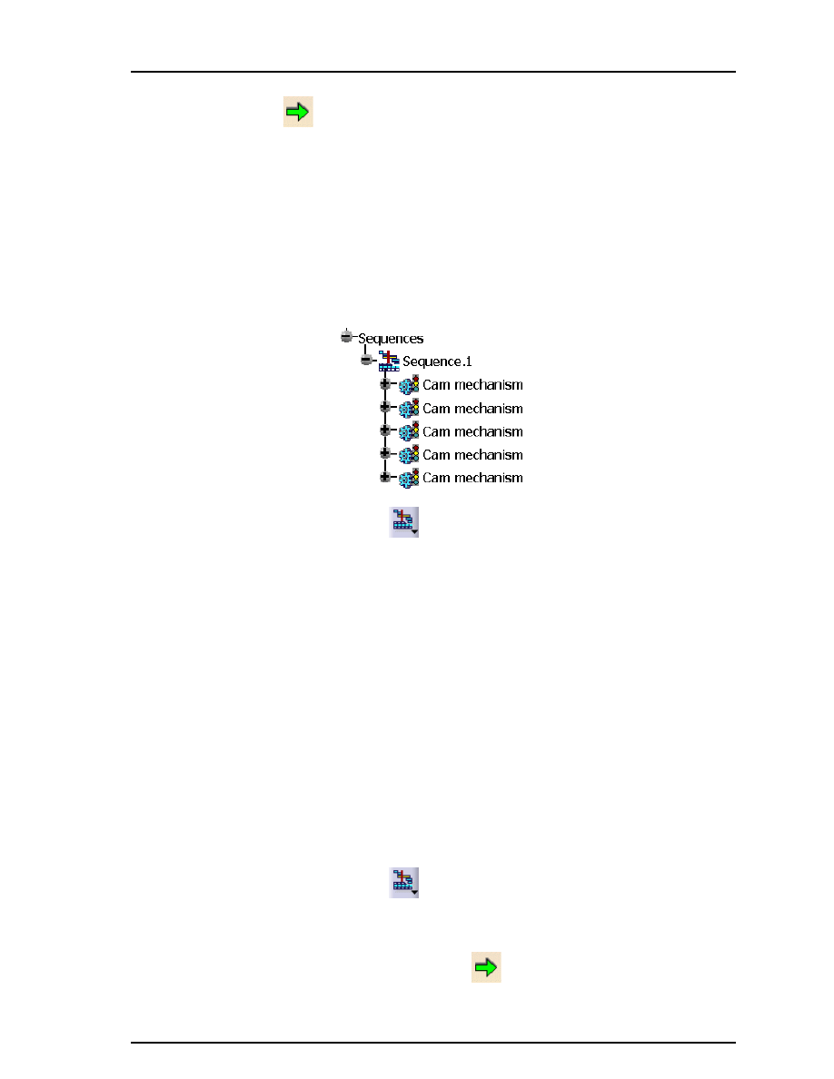
Select the Cam mechanism simulation from the window and select the green arrow
pointing to the right.
The simulation is put into the sequence. The default duration
is 72s.
Insert the Cam mechanism simulation again. You can do this in the same manner as you
did previously.
Insert the Cam mechanism simulation three more times. This will give you five full
turns of the mechanism.
Select OK. The sequence is created and you will have a Sequences branch under the
Applications branch.
Select the Edit Sequence icon again.
The Edit Sequence window appears. This time
you have Sequence.1 as an available action as well as the Cam mechanism simulation. You
are going to create a sequence that has five revolutions of the mechanism but at twice the
speed.
Insert the Cam mechanism simulation and change the Action duration to 36. The
duration will change in the window after you select another option.
Insert the Cam mechanism simulation again and change the Action duration to 36.
Insert the Cam mechanism simulation three more times making each one have a
duration of 36.
Select OK. Sequence.2 is created.
Create another sequence with the Cam mechanism simulation inserted five times with
a duration of 144 each. You should have three sequences created. You are going to create
one sequence that contains all three sequences.
Select the Edit Sequence icon again.
The Edit Sequence window appears. The three
sequences should appear as available actions.
Turn on the Iterative create last step and add option, select all three of the sequences
and select the green arrow pointing to the right.
The three sequences are inserted
consecutively. You will need to the use the
Ctrl
or
Shift
key in order to select all three at
once.

CATIA Kinematics
CATIA® V5R19
Kinematics - Simulations, Page 206
©Wichita State University
The sequence should look similar to the one shown below.
Select the Parameters icon in the Player window and change the Sampling Step to 3.0s
and the Temporization to 0.0s.
This will play the sequence at a rate of 3s per step.
Move the windows so that you can see the mechanism work and select the Play
Forward icon in the Player window.
Notice that the cam turns faster after five
revolutions and then slows down after another five revolutions.
Select OK in the Edit Sequence window. All of the windows close. Sequence.4 appears in
the specification tree as shown below.
You are going to generate a replay from the sequence, however, you cannot use the compile
simulation icon to do this. The compile simulation icon only works with simulations. You
are going to have to use a different option found in the pull down menus.

CATIA Kinematics
CATIA® V5R19
Kinematics - Simulations, Page 207
© Wichita State University
Generate Replay
The generate replay option is found in the pull down menus and is used to generate a replay
out of any item that has motion. It can be used with a simulation or sequence unlike the
compile simulation option which only works with a simulation. The generate replay option
will not generate a video or movie file. If you want to do that, you need to use a different
option.
Select pull down menu Tools, Simulation, Generate Replay. A Player window appears
and it is waiting for you tell it which item you want to use to create the replay.
Select Sequence.4 from the specification tree. The Replay Generation window appears.
Select OK. The replay is generated. This may take a couple of minutes since it has to run
through the entire sequence to generate the replay.
Select the Simulation Player icon and then Replay.2 from the specification tree.
The Player window appears. The icon may be located under the sequence icon. This will
allow you to play the replay.
Change the Sampling Step to 2.0s under the Parameters icon.
Select the Play Forward icon.
Notice that the replay plays faster than the sequence
due to the calculations that took place when generating the replay.
Close the Player window. If you want to generate a video or movie file you need to use
another option.
CATIA Kinematics
CATIA® V5R19
Kinematics - Simulations, Page 208
©Wichita State University
Generate Video
The generate video option will allow you to create a video or movie file from any item that
has motion. This is similar to creating a video file using the compile simulation icon but it
works with other items besides simulations.
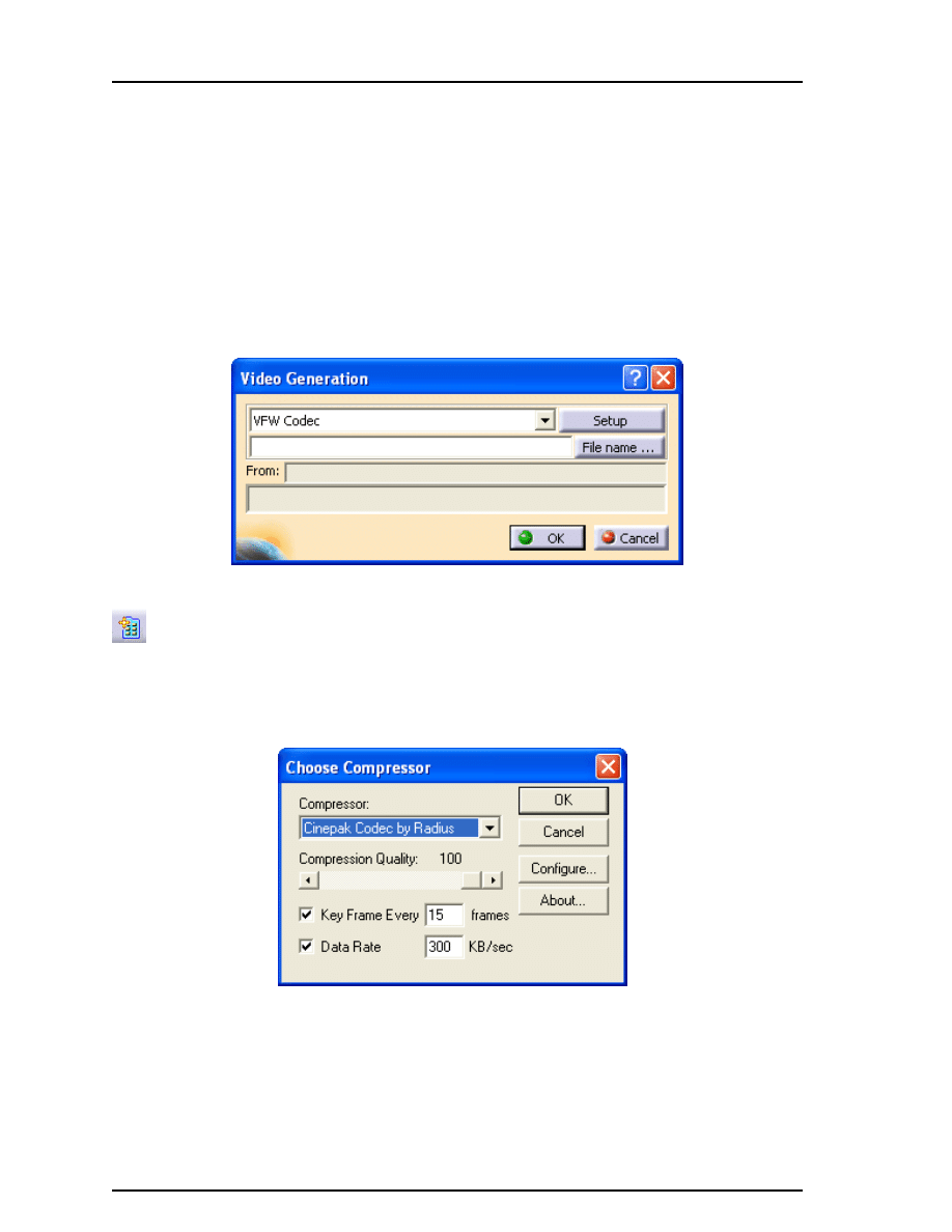
Select pull down menu Tools, Simulation, Generate Video. A Player window appears and
it is waiting for you tell it which item you want to use to create the video or movie file.
Select Replay.2 from the specification tree. You could have selected the sequence if you
preferred. The Video Generation window appears. You have the same options of creating
an video file or a series of images.
Change the Sampling Step to 5.0s under the Parameters icon in the Player window.
Select the Setup button in the Video Generation window. The Choose Compressor
window appears. You are going to change the compressor to make the video file a
reasonable size.
Change the Compressor to Cinepak Codec by Radius and drag the Compression Quality
to 100.
Select OK in the Choose Compressor window. The window closes.

CATIA Kinematics
CATIA® V5R19
Kinematics - Simulations, Page 209
© Wichita State University
Select the File name... button in the Video Generation window. The File Selection
window appears.
Go to your area and make the File name Cam and select Save. The path and file name
appear in the window.
Turn off the display of your specification tree and select OK. Press
F3
to turn off the
specification tree or you can select pull down menu View, Specifications. The video file is
being generated. This will take quite a while due to the size of the file. When it is finished
all of the windows will close.
Turn your specification tree back on.
Minimize CATIA and go to your area and play the Cam video file. You can play it by
double selecting on it. As you can see, the file can be viewed outside of CATIA.
Close the media player and go back to CATIA. You have to be careful generating video
files because they can become very big files.
Save and close your document. This exercise introduced how to use the simulation tools.
Later in the course, you will use these tools along with other options.
CATIA Kinematics
CATIA® V5R19
Kinematics - Path Generation, Page 224
©Wichita State University
Path Generation
There are a couple of methods to generate the path of an object. You can either create a
trace or a swept volume. A trace will create a wireframe path whereas the swept volume
will create the actual volume of the path.
Traces
Traces allow you to define a point, line or any combination of those elements and it will
create wireframe geometry showing the path those elements take during simulation. The
trace will only work if you have a replay created or if the mechanism can be simulated with
laws.
Open the Trace - Swept Volume document located in the Path Generation directory.
You will see a mechanism that you worked with earlier. There already is a simulation and
replay generated for this mechanism, but, there are no laws associated with the mechanism.
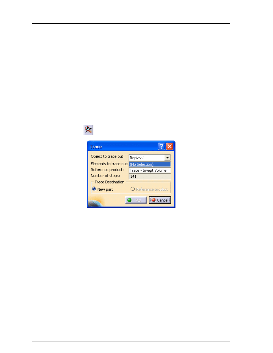
Select the Trace icon.
The Trace window appears.
Object to trace out
Defines the replay or mechanism that will be used to perform the
trace. In order for a mechanism to be available it has to have a law.
Elements to trace out Defines the elements that will be traced, either a point, line or a
combination of those
Reference Product
Defines which part or product will contain the trace. If a product is
chosen then a New Part will be created within the product that
contains the trace.
Number of steps
Shows how many steps will be involved in the object you chose to
trace. You cannot change the number of steps within the Trace
window, it is determined by the object. If you want the number of
steps to be different you will have to change them within the object
itself.
Trace Destination
You can specify whether you want the trace to go into a New Part or
the Reference Product. If the Reference Product is a product then
only the New Part option is available.
CATIA Kinematics
CATIA® V5R19
Kinematics - Path Generation, Page 225
© Wichita State University
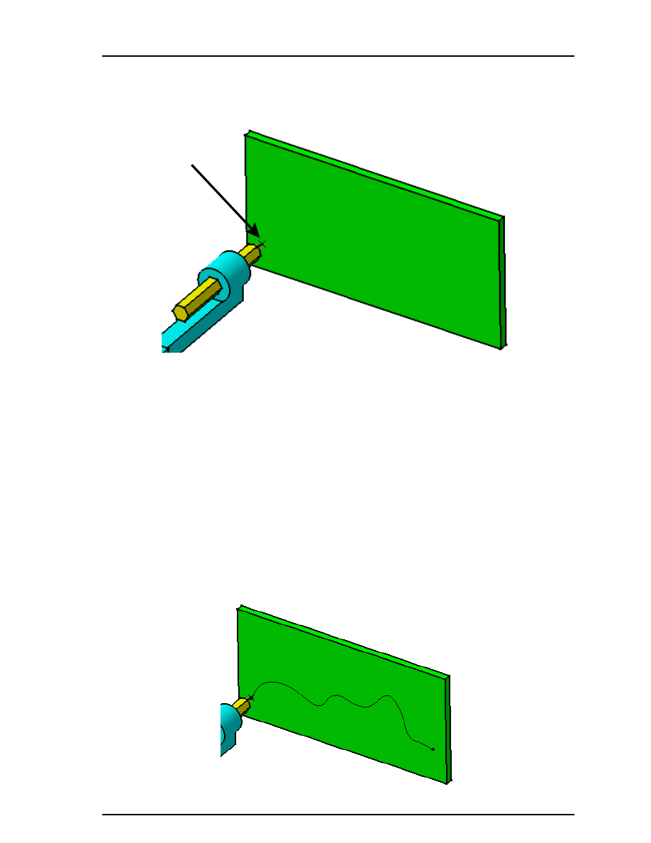
Select the point at the end of the pencil that touches the flat block as shown below.
This defines the element that you are going to trace. The only object that you can use to
create the trace is Replay.1.
Select in the Reference Product box and select the Block. You can select it either in the
specification tree or from the graphic area.
Make sure the Trace Destination is set to Reference Product and select OK. The trace is
created and it appears on the block. You are going to open the block to take a better look at
it.
In the specification tree, press the third mouse button while on the Block, select
Block.1 object and Open in New Window. The part is opened in a new window.
Hide all of the points. You can do this by using pull down menu Tools, Hide, All Points.
You should see a spline that was generated from the trace.
Save and close this document. You should see the mechanism with the spline on the
block.

CATIA Kinematics
CATIA® V5R19
Kinematics - Path Generation, Page 226
©Wichita State University
Select the Trace icon again.
The Trace window appears.
Select the point at the end of the pencil that touches the contoured base. This time you
are going to use the main product as the Reference Product.
Notice that the Destination of the trace is New Part and select OK. A new part window
appears with the trace.
Hide all of the points and planes. You can do this in the same manner as you did earlier.
Save and close this document. You should see your mechanism again.
Insert the Trace1 document into the assembly. The trace appears in the assembly.
Save your document. You are going to create a swept volume using the dark blue part.
CATIA Kinematics
CATIA® V5R19
Kinematics - Path Generation, Page 227
© Wichita State University
Swept Volumes
Swept volumes are used to create volumes that represent the total space an object or objects
use when in motion. These can be saved as cgr files which are “light” models and then
inserted into assemblies to check for interferences. Just like the trace, the swept volume
will only work with a replay or a mechanism with laws.
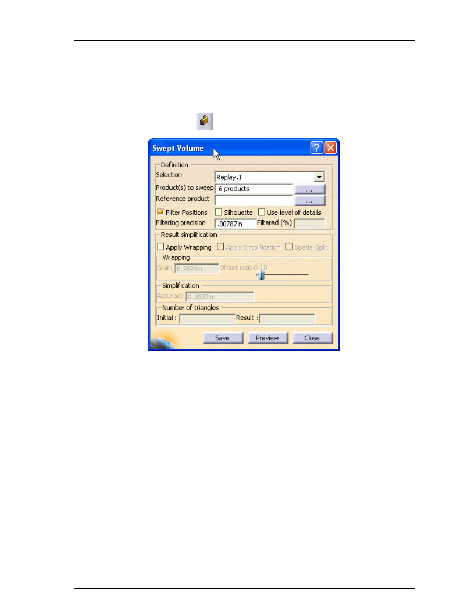
Select the Swept Volume icon.
The Swept Volume window appears.
Selection
Defines the item that will be used to perform the motion
Product(s) to sweep
Defines the objects that will be used to create the swept volume
Reference product
Allows you to define a moving product that you want the product(s)
to sweep to reference
Filter Positions
Reduces the number of positions that will be kept in the swept
volume
Filtering precision
Defines the maximum distance allowed between the filtered result
and the non-filtered result
Result simplification Simplifies the resulting volume by using Wrapping and
Simplification. These are only available if you have the DMU
Optimizer license.
Number of triangles
Shows the number of triangles used to create the swept volume. The
Result value is how many triangles there are after optimizing with
wrapping or simplification.
CATIA Kinematics
CATIA® V5R19
Kinematics - Path Generation, Page 228
©Wichita State University
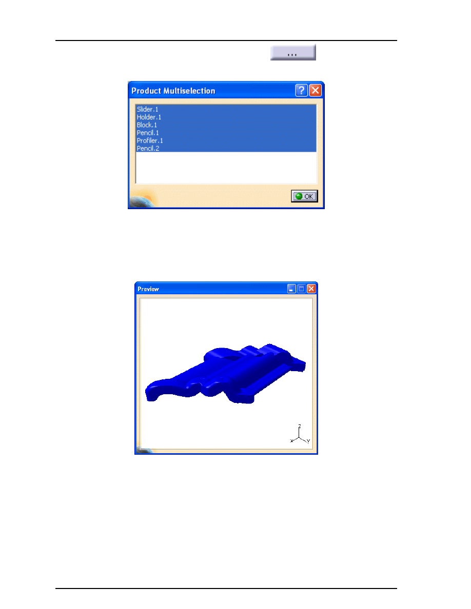
Select the Browse icon next to the Product(s) to sweep.
The Product
Multiselection window appears.
Select the Profiler.1 object from the window and select OK. This will be the product that
you are going to sweep. By default the Filter Positions option is on.
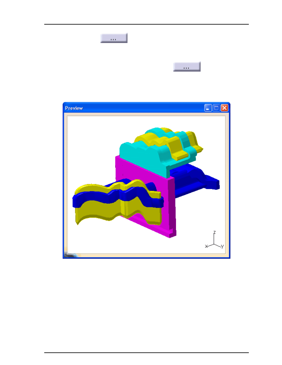
Turn off the Filter Positions option and select Preview. A Preview window appears
showing you the result. Notice the number of triangles.
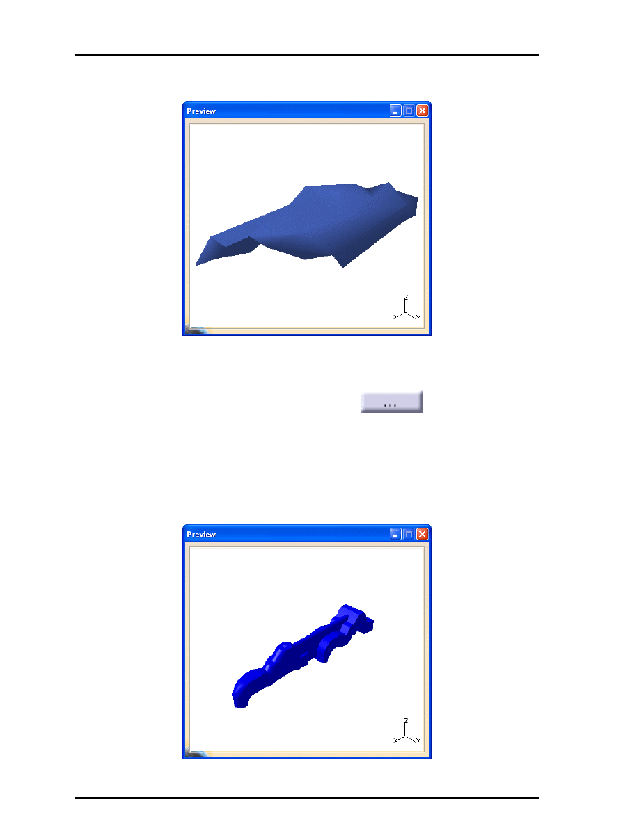
Turn on the Filter Positions with a Filtering precision of 0.005 and select Preview. The
preview does not look that much different but it is comprised of fewer triangles and it
filtered a majority of the positions.

CATIA Kinematics
CATIA® V5R19
Kinematics - Path Generation, Page 229
© Wichita State University
Change the Filtering precision to 0.1 and select Preview. You can see how the volume
becomes less smooth as you increase the precision. This filtered more of the positions and
is using even fewer triangles.
Change the Filtering precision back to 0.005, turn on the Apply Wrapping option using
the default values and select Preview. This is like taking a plastic sheet and wrapping the
volume with it. Notice that the wrapping reduced the number of triangles.
CATIA Kinematics
CATIA® V5R19
Kinematics - Path Generation, Page 230
©Wichita State University
Turn on the Apply Simplification option using the default values and select Preview.
The number of triangles is reduced.
Turn off the Apply Simplification and Apply Wrapping options and select Preview. You
are going to define a reference product for this swept volume.
Select the Browse icon next to the Reference product.
The Reference
Product Selection window appears.
Select the Slider.1 object from the window and select OK. This will show the motion of
the profiler with respect to the slider.
Select Preview. The only motion is back and forth since the slider moves sideways with the
profiler.
CATIA Kinematics
CATIA® V5R19
Kinematics - Path Generation, Page 231
© Wichita State University
Select the Browse icon next to the Reference product, select the Slider.1 object from the
window and select OK.
This removes the object so that there is not a
reference product defined.
Select the Browse icon next to the Product(s) to sweep, select the Slider.1, Holder.1,
Pencil.1, Profiler.1 and Pencil.2 objects and select OK.
You will probably
have to use the
Ctrl
key to select all of them. There should be 5 products in the Product(s)
to sweep box.
Select Preview. All of the objects are used for the swept volume.
Select Save in the window. A Save As window appears. You can save the swept volume
as a cgr, wrl, model or stl file. A cgr is a computer graphic representation, a wrl is a VRML
file for web viewing, a model file is a V4 file type and an stl is for stereolithography.
Save each swept volume in your area using the default name as cgr files. You are going
to insert these files into your assembly.
Select Close. The windows close.

CATIA Kinematics
CATIA® V5R19
Kinematics - Path Generation, Page 232
©Wichita State University
Insert the five swept volumes into this assembly. Your assembly should appear similar to
the one shown below.
Save and close your document.
Document Outline
- Back Cover with Blank.pdf
- Slide Number 1
- Slide Number 2
Wyszukiwarka
Podobne podstrony:
DESIGN, SIMULATION, AND TEST RESULTS OF A HEAT ASSISTED THREE CYLINDER STIRLING HEAT PUMP (C 3)(1)
Simulating and optimising worm propagation algorithms
Baudrillard Simulacra and Simulation
DESIGN, SIMULATION, AND TEST RESULTS OF A HEAT ASSISTED THREE CYLINDER STIRLING HEAT PUMP (C 3)(1)
ROOM ACOUSTIC SIMULATION AND AURALIZATION – WESPAC8
Jean Baudrillard Simulacra and Simulation
Process Modeling, Simulation, and Control for Chemical Engineers 2E
Kang, Meng Sound Propagation in Micro Scale Urban Areas Simulation and Animation
7 3 1 2 Packet Tracer Simulation Exploration of TCP and UDP Instructions
Fluid Dynamics Theory Computation and Numerical Simulation
Control Systems Simulation using Matlab and Simulink
Lab 5, 7.3.1.2 Packet Tracer Simulation - Exploration of TCP and UDP Instructions
56 793 814 Thermal Fatique of a Tool Steel Experiment and Numerical Simulation
Gade, Lisa, Lynge, Rindel Roman Theatre Acoustics; Comparison of acoustic measurement and simulatio
Modeling And Simulation Of ATM Networks
Identification and fault diagnosis of a simulated model of an industrial gas turbine I6C
Multiscale Modeling and Simulation of Worm Effects on the Internet Routing Infrastructure
Being Warren Buffett [A Classroom Simulation of Risk And Wealth When Investing In The Stock Market]
Simulation for Fuel Cell Inverter using Simplorer and Simulink
więcej podobnych podstron