http://users.otenet.gr/~athsam/electrocompaniet.htm
ith output of 25W per channel into 8ohms, this power amplifier, presents exceptional interest for
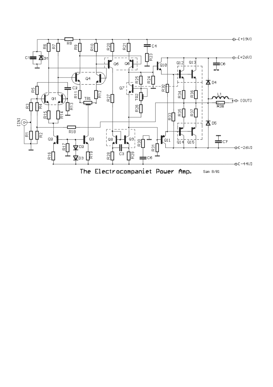
he circuit is designed with regard to reducing T.I.M (Transient Intermodulation Distortion).
bserving the circuit of amplifier, we will see that it is separated in four stages. The three first are
e
the first differential stage Q1 is BCY87 (Philips), in a metal case. The input impedance R1 of the
Ferranti).
the second differential stage Q4- BCY89 (Philips), trimmer TR1, adjusts for output offset
d
he third differential stage Q5-Q6, is supplied with current from current mirror Q8-Q9. These
, 8,
7 and TR2 are a Vbe multiplier, in thermal contact with the output stage
he output stage is the classic Darlington pair for positive and negative supplies. D4 & D5 protect
W
many, and it applies enough technological solutions, that we do not find in a lot of other amplifiers.
T
O
full differential amplifiers (in thermal equilibrium, for minimal change in characteristic with
temperature variation) and the fourth stage of the classic Darlington arrangement, with Vb
multiplier transistor so set bias current in the output stage.
In
amplifier is very low 1.8K, compared to most amplifiers which are between 47K-100K.
The two first differential amplifiers are supplied by current sources Q2 and Q3 ZTX384 (
The base of Q1 is applied the negative feedback via R18, R2, R4. Compensation for high
frequencies is provided by R5 and C2.
In
voltage. The constant current sources are roughly 0.2mA for first stage and 0.4mA for secon
stage.
T
function to increase the speed and the linearity of stage. Thermal balance is ensured as Q5, 6
9 are all in thermal contact.
Q
T
the output transistors from speaker back emf.
A other point of difference is the driver stags are supplied with non symmetrical regulated power
supplies of +19V and -44V and the final stage with and unregulated +/- 26V. This segregation of
power supplies improves the Power Supply rejection ratio for low noise and decreases the
intermodulation and the distortion.
R1-3-19= 1.8Kohms
R24-31= 2.2Kohms
D1= 15V 0.5W Zener
R2= 10 ohms
R25= 2.7Kohms
D2-3= 1N4148
R4= 12Kohms
R28-29= 10 ohms
D4-5= BY206
R5= 120 ohms
R32-33= 56 ohms
Q1=
BCY87
(Philips)
R6-7-27= 1Kohms
R34-35= 1 ohms/5W
Q2-3= ZTX384
(Ferranti)
R8-13= 2.7Kohms
R36-37= 1 ohms/5W
Q4=
BCY89
(Philips)
R9-10= 1Kohms
R38= 1 ohms/ 3W
Q5-6=
R11-12= 33 ohms
C1-6-7= 100nF 100V Polyester
BD139
R14-15-20-21= 10 ohms
C4-5= 680nF 100V Polyester
Q10= BD139
R16= 3.3Kohms
C2= 2.2nF 100V Polyester
Q11= BD140
R17= 4.7Kohms
C3= 2.5nF 100V Polyester
Q12-13=
BD203
R18-26= 470 ohms
TR1= 220 ohms Trimmer
Q14-15=
R23-30= 1 ohm
TR2= 1Kohms Trimmer
All R is metal film 1% except R34-
38
SPECIFICATIONS
OUTPUT POWER
25W/8 ohm - 40W/4 ohm
DAMPING FACTOR
160 [8 ohm]
INPUT IMPEDANCE
1Kohm
SLOW RATE
125V/μs
FREQUENCY RESPONSE
1W/8 ohm DC-1MHZ
THD
0.01% 12.5W
TIM
0.03% 12.5W
S/N
100dB
Wyszukiwarka
Podobne podstrony:
3Y11 schematic diagram(90 260v)
Laser Schematic Diagram
Genesis B200 Stelth pwr Schematic Diagram
Cambridge P60 int Schematic Diagram1
Cello Encore Schematic Diagram
Cambridge P500 pwr Schematic Diagram
Cygnus PA1800D int Schematic Diagram
Classe 70 pwr Schematic Diagram
Quad 33 pre Schematic Diagram
Phonic MAX860 1500 2500 pwr Schematic Diagram
Cambridge T55 tun Schematic Diagram
Jbl Arc Sub Schematic Diagram
Beocenter 1400 int Schematic Diagram
Cambridge P50 v1 int Schematic Diagram
Marantz 4100 Schematic Diagram
Rogers Cadet III pwr Schematic Diagram
Cambridge P100 int Schematic Diagram
Lecson Ap 1 Schematic Diagram
więcej podobnych podstron