
Suzuki Samurai Air Compressor Conversion Project
By Jim Cambron
You can convert your Samurai Air Conditioning compressor for use as an air compressor. It does not cost much
to do and it’s a fairly simple project. These instructions can also be used to build a similar compressor system
on other vehicles.
You should consider doing this project if you have a need for air for inflating tires after off-roading, you are
installing air lockers or you want to inflate camping matteresses and other items. If you add a pressure switch
and a tank, you can also operate small air-powered tools to a limited degree.
You should NOT consider doing this project if you plan to add power steering or you like air conditioning in
your Samurai.
There are a number of ways to do this conversion. The most common ways are with a pressure switch and tank
and without a pressure switch and tank. If you only want to inflate tires or power your locker(s) you can do
without the pressure switch and tank. However, a pressure switch and tank adds a great deal of usefulness and
safety to the system. You should seriously consider the inclusion of these two items is you want to get the most
usefulness out of this conversion. See the Operations section at the end of this document for details.
Basic parts list.
Some specific items, such as the Campbell-Hausfield air tool set and parts assortment, may not be available in
your area. If you have to buy most items separately, refer to figure 1 for part name and count. Note that all the
copper fittings, couplers and other components are labeled 1/4” NPT. This represents the inside diameter hole
size (in English measurement units) and NPT the type of threads on the part. NPT is a standard English
plumbing thread type if you have metric components where you live, use the metric counterparts.
Part
Description
Source
Rough
Cost
Samurai
Compressor
junkyard
$0.00
to
?
Outlet connector from A/C Assembly
junkyard
$0.00 to ?
2 - 3/8” – 7/8” clamps
hardware store
$1.38
1 - 25’ air hose with ¼” NPT nipples
hardware store
$9.90
2 - barb hose, 1.4” NPT
hardware store
$1.86
1 - 90-degree brass ¼” NPT elbow
hardware store
$2.25
1 - 1/4” NPT brass tee
hardware store
$2.89
1 - Campbell-Hausfeld air tool set (tire gage, air chuck, tire
inflation chuck, snap connector assortment, etc.)
hardware store
$14.89
2 - female snap air fitting/coupler
hardware store
$2.19
1 - male snap air fitting/coupler
hardware store
$1.06
1 - ¼” NTP hex nipple
hardware store
$1.33
1 - 125 PSI ASME coded pop-off safety valve ¼” male NPT hardware store
$9.98
1 – automatic line oiler ¼” male NPT
hardware store
$18.99
1 – roll Teflon plumber’s tape
hardware store
$0.59
1- 12V illuminated toggle switch (Radio Shack 25-50706)
Radio Shack
$2.79
----------
total:
$70.10
Tank items:
1
-
compressor
gage
Hardware
Store
$14.89
2 - 1/4” NPT brass tee
hardware store
$2.89
1 - 25’ length of air hose with ¼” NPT nipples on each end
hardware store
$9.90
(or build one with air hose and 2 barb hose to ¼” nipples)
1 - Pressure switch
hardware store
$48.00 (ballpark)
----------
total:
$75.68
Tank adapter for Basic conversion:
Part
Description
Source
Rough
Cost
1 - male snap air fitting/coupler with ¼” NPT tread end
hardware store
$1.06
1 – male snap air fitting coupler with ¼” NPT nipple end
hardware store
$1.89
--------
Total
$2.95
Construction:
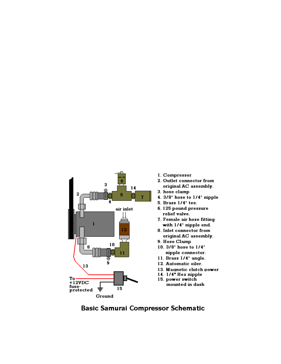
Refer to Figure 1 for parts placement. Be sure to wrap all threads with Teflon plumbers tape (or similar sealing
product) as you assemble the plumbing. Note that the outlet connector on the compressor is the one CLOSEST
TO the engine block and the inlet connector is the one that is the farthest away from the engine block.
I used hose clamps and the original compressor hoses and hose clamps to simplify adapting the air plumbing
from Metric to English. Since the United States has not completely adapted ourselves to the metric standard,
finding metric fittings for the compressor outlet and inlet is difficult and expensive. Recycling the original hose
lines and using hose clamps solves this problem. It also makes for an easier to repair system.
There is another description of this conversion on the Internet that involves the use of a ½” iron plumbing tee
and an epoxy-like substance called J-B weld. The idea is to liberally apply J-B weld to the right-angle port of the
tee, then screw it onto the metric threaded outlet port of the compressor. I guess this is okay in a pinch, but it is
prone to pinhole leaks if not done properly and is very permanent! The hose clamp method allows you to easily
adjust the positioning of the components and does not permanently change the compressor’s outlet connector.
Figure 1

If you want to use the basic design to fill an air tank, try the tank design in Figure 2. You will also need to make
the adapter pictured in Figure 3. The double-ended male connector adapter allows you to connect the air tank in
figure 2 for filling through an air hose. If you already have a tank, examine the way the tank is filled and create a
suitable adapter for it. Be sure to check for a one-way check valve on your tank if you want to use the adapter in
Figure 3. If there is one installed in line with the tank’s outlet connector, you will not be able to fill the tank
with the adapter.
Although the 125 pound pressure relief ( item 6 in the schematic) valve will provide protection from over-
pressurizing a tank, YOU MUST STILL CAREFULLY MONITOR THE PRESSURE ON THE TANK’S
GAGE DURING THE FILLING PROCESS TO KEEP IT FROM ACCIDENTALLY OVERFILLING THE
TANK CAUSING THE TANK IT TO EXPLODE!
Figure 2 Figure 3
If you would like to permanently add a tank to your basic compressor, use the schematic in Figure 4. It uses a
pressure switch that is designed to automatically shut off the compressor when a maximum pressure is reached –
usually no more than 125 pounds and turn the compressor back on when the pressure drops to a minimum level –
usually around 60 to 80 pounds. This system MUST use a pressure switch in order to work safely and properly.
In addition, the pressure switch makes the system work a lot easier! See the Operation section at the end of the
article for details.

Figure 4
Picture 1
Picture 1 is an example of how the compressor and plumbing is installed on my vehicle. You can place your air
hose connector and tank wherever you want on the vehicle body. Just be sure that you keep the lines away from
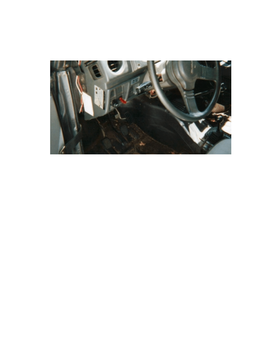
heat and the potential for damage from objects while on the trail. Picture 2 shows how I mounted the power
switch (the red switch next to the dimmer knob) on my dash
Picture 2
Although some people use their hollow steel bumper as an air tank, there is a REAL danger of flying shrapnel
should a pressurized bumper be torn open in an accident. Something to think about…
Operation
I have installed the basic system in my Samurai without a pressure switch and a permanent tank.. Operating it
REQUIRES two people – one to operate the compressor switch and the throttle and one to inflate the tire or
other item. Here is what I do when I inflate something (tires, air mattresses, etc.) with the Basic Compressor
setup:
1. Make sure that the compressor switch is turned off.
2. Pull up on the pressure relief valve to depressureize the output side of the compressor.
3. Connect the air hose and appropriate tool (usually an tire inflating chuck) to the output of the compressor.
4. Start the engine and idle up to around 2000 RPM.
5. Connect the air hose to the item to be inflated. If you are using a tool with a trigger, press the trigger.
6. Start the compressor to inflate.
7. Turn off the compressor and release the throttle to disconnect and check the air pressure.
8. Repeat steps 4 through 7 until the item is properly inflated.
If you have installed the pressure switch and a permanent tank, you only need one person to operate the system.
Here is what you need to do:
1. Start the engine.
2. Connect the air hose and tool to be used.
3. Turn on the compressor.
4. If the system is discharged, let the pressure build up until the pressure switch shuts off the compressor.
5. Use the air tool stopping as necessary for the compressor to “catch up” with air useage.
6. Turn off the compressor when done.
There you have it. Have fun and be careful on the trails!
Document Outline
Wyszukiwarka
Podobne podstrony:
How To Multiply Your Baby vol 1D a4
Obrigado how to express your gratitude in Portuguese
How To Multiply Your Baby vol 1C a4
How To Multiply Your Baby vol 1A a4
How to prepare your Curriculum Vitae
How to Create Your Future
How To Meet Your Gay Mate Get a Gay Date
How to Attain Your Desires
How to make your own power Bleeder
How to Make Your Own Perfume
How to improve your English
How to Change Your Life Around in 30 days
Change Your Mind How to Change Your Thought Patterns to Change Your Reality
APA style How to present your paper
how to activate your mb star
How To Multiply Your Baby vol 1B a4
How to Write your College Application Essays
Bazooka How To Build Your Own
więcej podobnych podstron