I24201
Instrument Panel J/B
I10
Ignition SW
Engine Room J/B
Battery
FL MAIN
ALT
IG1 Relay
AM1
IG1
J7
J/C
+B
C14
RH J/B
2
IG
A
IA
IF
6
3B
IF
B
W–B
5
1A
1
2
3
1
1
12
2
2
1
IF
9
IB
1
AM1
ECU–IG
IH
10
B–W
B–W
5
3B
W
C14
16
GND
W–B
A
J6
J/C
IE
4B
14
4B
21
Center
J/B
W–B
W
W
1C
1
1D
1
W
W–B
Cruise Control
ECU Assy
B–Y
W
2
1
–
DIAGNOSTICS
CRUISE CONTROL SYSTEM (April, 2003)
05–779
944
Author:
Date:
2004 COROLLA (RM1037U)
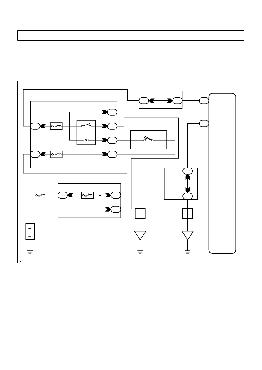
ECU POWER SOURCE CIRCUIT
CIRCUIT DESCRIPTION
The cruise control ECU assy power source supplies power to the actuator and sensors, etc., when terminal
GND and the case of the cruise control ECU assy are grounded.
WIRING DIAGRAM
0527C–06
I32648
ECU –IG
Fuse
Instrument Panel J/B
I30401
GND (–)
+B (+)
05–780
–
DIAGNOSTICS
CRUISE CONTROL SYSTEM (April, 2003)
945
Author:
Date:
2004 COROLLA (RM1037U)
INSPECTION PROCEDURE
1
CHECK FUSE(ECU–IG)
(a)
Remove the ECU–IG fuse from the instrument panel J/B.
(b)
Check the continuity of the ECU–IG fuse.
OK: Continuity
NG
REPLACE FUSE
OK
2
INSPECT TERMINAL VOLTAGE(B)
(a)
Remove the cruise control ECU assy with connector still
connected.
(b)
Turn the ignition switch to ON.
(c)
Measure voltage between terminals 2 (B) and 16 (GND)
of the cruise control ECU assy connector.
OK:
Voltage: 10 – 16 V
OK
PROCEED TO NEXT CIRCUIT INSPECTION
SHOWN ON PROBLEM SYMPTOMS TABLE (See
page
NG

I30401
GND
–
DIAGNOSTICS
CRUISE CONTROL SYSTEM (April, 2003)
05–781
946
Author:
Date:
2004 COROLLA (RM1037U)
3
CHECK HARNESS AND CONNECTOR(BETWEEN CRUISE CONTROL ECU ASSY
AND BODY GROUND)
(a)
Measure resistance between terminal 16 (GND) of the
cruise control ECU assy connector and body ground.
OK:
Resistance: Below 1
Ω
NG
REPAIR OR REPLACE HARNESS OR
CONNECTOR
OK
CHECK AND REPAIR HARNESS AND CONNECTOR BETWEEN CRUISE CONTROL ECU ASSY
AND BATTERY
Wyszukiwarka
Podobne podstrony:
Power Source Current Flow Chart
Paralleling Arc Welding Power Sources
Power Source
Power Source
68 Power Sources
Power Source Current Flow Chart
Power Source Current Flow Chart
Paralleling Arc Welding Power Sources
circuit diagram of mig rx 250 power source
A Series Active Power Filter Based on a Sinusoidal Current Controlled Voltage Source Inverter
A Series Active Power Filter Based on Sinusoidal Current Controlled Voltage Source Inverter
A Composite Pwm Method Of Three Phase Voltage Source Inverter For High Power Applications
A Series Active Power Filter Based on Sinusoidal Current Controlled Voltage Source Inverter
więcej podobnych podstron