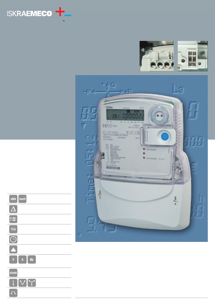
Energy Measurement and Management
Polyphase meter
MT174
MT174 is a polyphase multifunc-
tion meter used for measurement of
active, active and reactive or active,
reactive and apparent energy and
demand in three-phase four- or
three-wire networks. It can be con-
nected directly or via CT. The meter
can also be used in single phase
two-wire networks. The meters
comply
with
both
European
(EN 50470-1 and EN 50470-3) and
international (IEC 62052-11 and
IEC 62053-21) standards, and are
designed and manufactured in
compliance with the ISO 9001 stan-
dard. The kvarh-meter complies
with the IEC 62052-23 standard.
■
Fast and easy installation procedure, indications of correct connection
■
Compact meter case with IP54 protection
■
Multi-phasing connection (all-in-one: poly- and single-phase meter)
■
Universal current terminal for all types of conductors
■
Indications of meter operation status
■
Antifraud features
■
Very high EMC immunity level
■
Optical port and optionally RS485 interface
■
Internal real time clock
■
Powerful load profile recorder with up to 8 channels
One or two energy flow directions or always
positive registration
Internal real time clock
Measurement of phase
voltages, currents, power
factors and frequency
Load profile registration (8-channel)
Multi-phasing
Interface RS485
Multirate registration
Maximum demand and instantaneous power
Active, active and reactive or active,
reactive and apparent energy
Pulse output(s)
Option: Tariff output(s) instead of pulse output(s)
MT174
FUNCTIONAL AND TECHNICAL DATA
The MT174 polyphase meter is intended for residential and small
commercial customers. It is used for revenue measuring of active, active
and reactive or active, reactive and apparent energy and demand in three-
phase four- or three-wire networks.
Measuring and registration:
– One energy flow direction (import)
– Two energy flow directions
– Always positive (absolute)
– Four-quadrant for reactive energy (option)
Accuracy/calibration: There is no need for meter recalibration due to long-term
metering stability.
Indications:
LED 1 (red): kWh impulses
LED 2 (red): kvarh impulses (option)
LED 3 (red): kVAh impulses (option)
Blinking: the load current is higher than the starting current
Lit: voltage applied to the meter, the load current is smaller than the starting
current
Turned-off: no voltage applied to the meter
Communication: Optical port (IEC 62056 – 21) for local meter programming and
data downloading, RS485 serial interface.
Multi-phasing metering operation: The meter can be connected as a single, two- or
three-phase meter.
Multirate registration: Internal time-switch or external tariff changeover.
Programmable number of rates (1 … 4 rates, 10 day types, 10 seasons, 46 holidays).
7-segment LCD:
– In compliance with VDEW recommendation, 8 digits for data + 5 digits for EDIS
code (DIN 43863-3) + 11 signal flags; indicators: energy flow direction and
presence of phase voltages
– Automatic scroll mode
– Manual scroll mode (with a pushbutton)
Programmable data set and sequence
Option: data display on LCD in no-voltage state
Real time clock:
– 32 kHz quartz crystal
– Time keeping accuracy better than prescribed by IEC 62054-21 standard
– RTC back-up power supply: Li-battery
– The real time clock enables: tariff changeover, seasons changeover, transition
to day light saving period and vice-versa, demand and load profile periods
Current terminals:
– Directly connected meters: A universal clamping type for all types of wires
(diameter ø = 9.5 mm or ø = 8.5 mm)
– Transformer operated meters: solid brass with bore diameter ø 5.5 mm
Enclosure: Self-extinguishing UV stabilized polycarbonate
Protection against water and dust: IP 54
TYPE DESIGNATION FOR ORDERING
M
T
174
–
D1
A4
1
R5
1
S5
–
V22
G22
–
M3
K
0
3
Z
M
–
Electronic meter
T
–
Three-phase three-element meter
174
–
Multi-tariff meter with LCD, RTC and maximum demand indicator
D1
–
Terminal block up to 85 A for direct connection
D2
–
Terminal block up to 120 A for direct connection
T1
–
Terminal block up to 6 A for indirect connection
A5
–
Active energy measurement, accuracy class A (by EN 50470-3)
2 (by IEC 62053-21)
A4
–
Active energy measurement, accuracy class B (by EN 50470-3)
1 (by IEC 62053-21)
1
–
Measurement in one energy flow direction
2
–
Measurement in two energy flow directions
4
–
Measurement in two energy flow directions, absolute registration
R6
–
Reactive energy measurement, accuracy class 3 (option)
R5
–
Reactive energy measurement, accuracy class 2 (option)
1
–
Measurement in one energy flow direction
2
–
Measurement in two energy flow directions
5
–
Measurement in four quadrants
6
–
Measurement in four quadrants and two energy flow directions
S6
–
Apparent energy measurement, accuracy class 3 (option)
S5
–
Apparent energy measurement, accuracy class 2 (option)
V12
–
1 tariff input
V22
–
2 tariff inputs
G12
–
1 pulse output, class A by IEC 62053-31(S0 by DIN 43864)
G22
–
2 pulse outputs, class A by IEC 62053-31(S0 by DIN 43864)
L11
–
1 optomos relay pulse output, make contact (option: tariff output)
L21
–
2 optomos relay pulse outputs, make contact (option: tariff outputs)
M3
–
RTC with Li-battery as back-up supply
K
–
Communication channel
0
–
Optical port in compliance with IEC 62056-21
3
–
RS485 (option)
Z
–
Load profile recorder (option)
7
2
2
.9
9
9
.1
2
4
1
0
0
7
/2
2
Iskraemeco, Energy Measurement and Management
4000 Kranj, Savska loka 4, Slovenia
Telephone: (+386 4) 206 40 00, Telefax: (+386 4) 206 43 76,
http://www.iskraemeco.si, e-mail: info@iskraemeco.si
Published by Iskraemeco. Data subject to alteration without notice.
Owing to periodical improvements of our products the supplied products can differ in some
details from the data stated in the prospectus material.
Accuracy class (kWh) . . . . . . . .A or B (by EN 50470-3) 2 or 1 (by IEC 62053-21)
(kvarh) . . . . . . . . . . . . . . . . . . . . . . . . . .3 or 2 (by IEC 62053-23)
(kVAh) . . . . . . . . . . . . . . . . . . . . . . . . . . . . . . . . . . . . . . . . . .3 or 2
Reference / Basic current I
b
. . . . . . . . .5, 10, 15, 20 A (directly connected meters)
1 A (CT operated meters)
Max. current I
max
. . . . . . . . . . .60, 80, 85, 100, 120 A (directly connected meters)
6 A (CT operated meters),
Min. current . . . . . . . . . . . . . . . . . . . . . . . . . . . . . . . . . . . . . . . . . . . . . . . . . .0.05 I
b
Starting current . . . . . . . . . . . . . . . . . . . . . . . .0.004 I
b
(directly connected meters)
0.002 I
b
(CT operated meters)
Reference voltage U
r
. . . . . . . . . . . . . .3 x 230/400 V, 3 x 400 V, 3 x 230 V, 230 V
Voltage range . . . . . . . . . . . . . . . . . . . . . . . . . . . . . . . . . . . . . . . . .0.8 U
r
... 1.15 U
r
Reference frequency . . . . . . . . . . . . . . . . . . . . . . . . . . . . . . . . . . . . .50 Hz or 60 Hz
Operating temper. range . . . . . . . . . . . . . . .-40°C ... +60°C (LCD: -25°C ... +60°C)
Extended temper. range . . . . . . . . . . . . . . . . . . . . . . . . . . . . . . . . . .-40°C ... +70°C
Storage temperature . . . . . . . . . . . . . . . . . . . . . . . . . . . . . . . . . . . . .-40°C ... +85°C
Optical port . . . . . . . . . . . . . . . . . . . . . . . . . . . . . . . . . . . . . . . . . . . . .IEC 62056-21
RTC (IEC 62054-21) . . . . . . . . . . . . . . . . . . . . . . . . . . . . . . . . . . . . . .
≤
±3 min/year
RTC operation reserve . . . . . . . . . . . . . . . . . . . . . . . . . . . . . . . .5 years (Li-battery)
Pulse output(s) IEC 62053-31, class A (S0) . . . . . .ti = 40 ms (10, 20, 30, ... 160 ms)
Optomos relay . . . . . . . . . . . . . . . . . . . . . . . . . .ti = 80 ms, ... 160 ms
Tariff output(s) . . . . . . . . . . . . . . . . . . . . . . . . .Optionaly instead of impulse output
Current circuit burden . . . . . . . . . . . . . . . . . . . . . . . . . . . . . . . . . . . . . . . . .<0.5 VA
Voltage circuit burden . . . . . . . . . . . . . . . . . . . . . . . . . . . . . . . . . . . . .<1 W / 10 VA
Dielectric strength . . . . . . . . . . . . . . . . . . . . . . . . . . . . . . . . . . . .4 kV, 50 Hz, 1 min
Impulse voltage
main circuits: . . . . . . . . .12 kV (aux. circuits: 6 kV), 1.2/50 µs
CT operated: . . . . . . . . . . . . . . . . . . . . . . . . . . .6 kV, 1.2/50 µs
Short-circuit current . . . . . . . . . . . . . . . . . . . . . . . . . . . . . . . . . . . . . . . . . . .30 I
max
Fast transients (burst) . . . . . . . . . . . . . . . . . . . . . . . . . . . . . . .6 kV (IEC 61000-4-4)
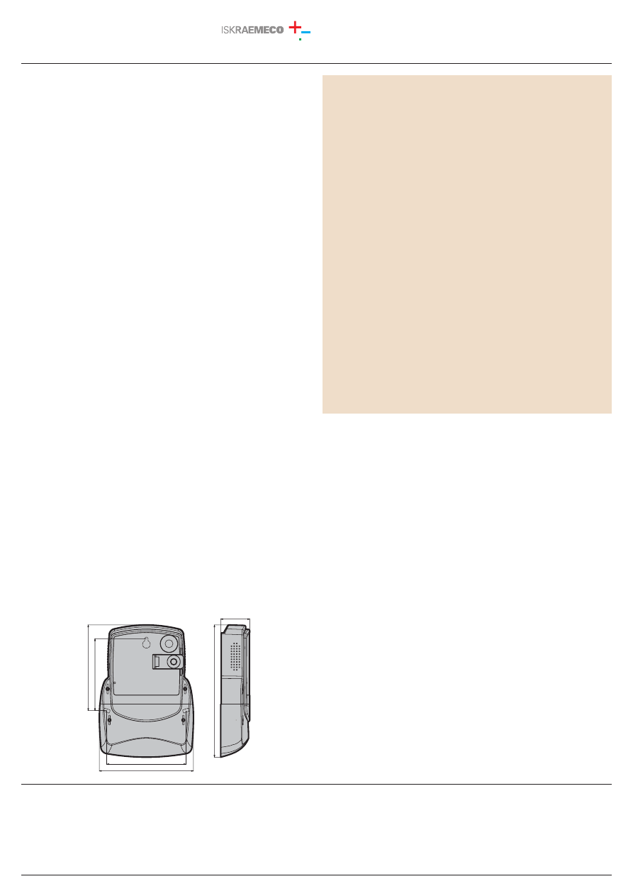
Dimensions . . . . . . . . . . . . . . . . . . . . . . . . . . . . . . . . . . . . . . . .250 x 178 x 55 mm
Mass . . . . . . . . . . . . . . . . . . . . . . . . . . . . . . . . . . . . . . . . . . . . . . . . . . . . . . . . . .1 kg
150
150
1
3
6
1
3
6
55
55
2
5
0
2
5
0
178
178
1
6
2
1
6
2
OVERALL AND METER FIXING DIMENSIONS
Wyszukiwarka
Podobne podstrony:
Volkswagen BETA Instrukcja obsługi PL, Elektronika, Instrukcje obsługi PL-radia samochodowe
Rieju RS2 KOSO instrukcja obługi licznika elektrycznego manual service
Instrukcja obsługi lodówka Elektrolux ERC 19002W8 i ERC 24002W8
instrukcja obslugi do Goclever TabI70 EN i PL
Instrukcja obsługi warsztatu elektrycznego poz 864 Nadrybie
Dane techniczne i instrukcja obsługi skanera ręcznego SKYPIX EN
Instrukcja obslugi EN
instrukcja obsługi elektrycznej maszynki do strzyżenia włosów Philips QC 5053, QC 5050, QC 5010 po p
Instrukcja BHP obsługi czajnika elektrycznego
Instrukcja Obslugi Audi A4 S4 Cabriolet en
instrukcja obslugi do Nokia CR 115 EN
Instrukcja obsługi stołowych wiertarek elektryczznych, Instrukcje w wersji elektronicznej
INSTRUKCJA BHP OBSŁUGI PATELNI ELEKTRYCZNEJ, instrukcje BHP
elektrody kombinowane instrukcja obslugi
Instrukcja obsługi obrabiarek, Instrukcje w wersji elektronicznej
więcej podobnych podstron