
DIFFERENTIAL & AXLE SHAFTS - FRONT
1993 Mitsubishi Montero
1993 Drive Axles - Differentials & Axle Shafts - Front
Ram-50 4WD, Montero, Pickup 4WD
DESCRIPTION & OPERATION
Front axle assembly consists of differential carrier, housing
tube, inner shaft and drive axles. See Fig. 1. A full-floating axle
design is used. Drive axles are flexible assemblies made up of inner
and outer CV joints. Birfield Joints (BJ) and Double Offset Joints
(DOJ) are used at opposite ends of each drive axle.
AXLE RATIO & IDENTIFICATION
AXLE RATIO SPECIFICATIONS TABLE
Application Ratio
Montero
LT31X10.50R15 Tire .................... 4.88:1
P235/75R15 Tire ....................... 4.63:1
Pickup & Ram-50 ......................... 4.22:1
LUBRICATION
CAPACITY
DIFFERENTIAL FLUID CAPACITY TABLE
Application Specification
Montero ........................ 2.6 Pts. (1.2L)
Pickup & Ram-50 ................ 2.3 Pts. (1.1L)
FLUID TYPE
All models use fluid type SAE 80W-90/API GL-5.
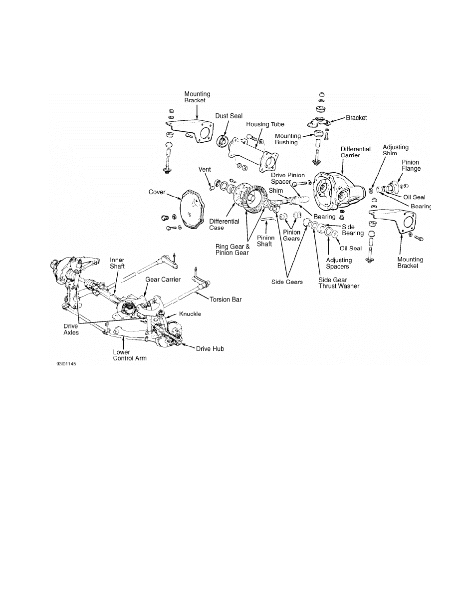
Fig. 1: View Of Front Differential Assembly & Suspension Components
Courtesy of Mitsubishi Motor Sales of America.
TROUBLE SHOOTING
See TROUBLE SHOOTING - BASIC PROCEDURES article in
GENERAL INFORMATION section.
REMOVAL & INSTALLATION
DRIVE AXLES
Removal
1) Raise and support vehicle. Remove wheels and undercover.
Ensure hub is in free-wheeling position. Place transfer case in 2H
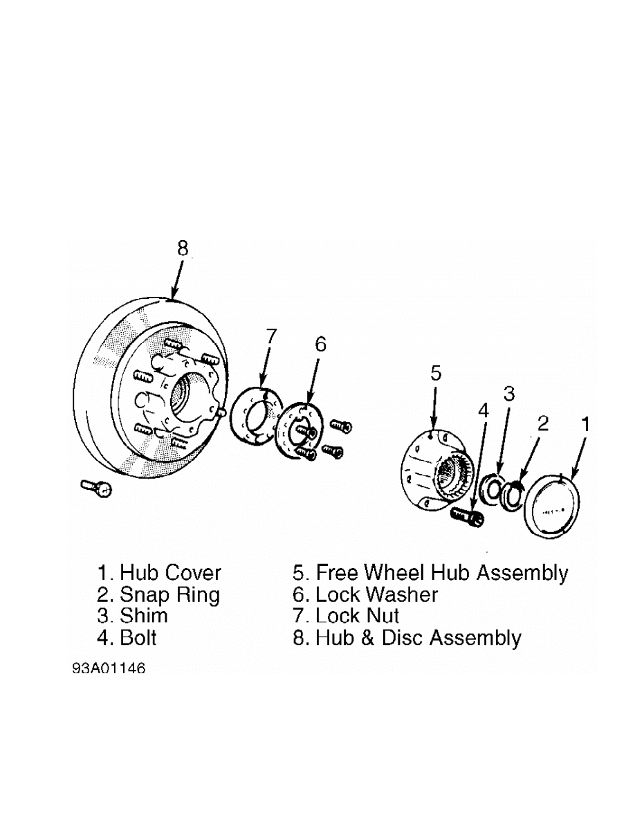
position. Remove drive hub cover, snap ring and shim from drive axle.
See Fig. 2. Remove brake calipers and support aside.
2) Disconnect tie rod assembly. Support lower control arm
with jack. Separate ball joints from knuckle. Remove knuckle and front
hub assembly. Using flat-blade pry bar, carefully remove left drive
axle from differential carrier. DO NOT damage oil seal. On right drive
axle, remove drive axle-to-inner shaft flange retaining bolts. Remove
right drive axle.
CAUTION: Replace circlips on BJ/DOJ splined shaft end.
Installation
1) Install right drive axle on inner shaft flange. Install
new circlip on DOJ side of left drive axle. Carefully install left
drive axle into differential. DO NOT damage oil seal.
2) Reinstall knuckle with front hub assembly. To complete
installation, reverse removal procedure. Install shim and snap ring.
Check axle end play. See Figs. 3 and 4. End play should be .016-.028"
(.4-.7 mm) on Montero, .008-.020" (.2-.5 mm) on Pickup and Ram-50. If
end play is not within specification, install correct shim.
Fig. 2: Exploded View Of Auto-Locking Hub Assembly (Pickup & Ram-
50 Shown, Montero Similar)
Courtesy of Mitsubishi Motor Sales of America.
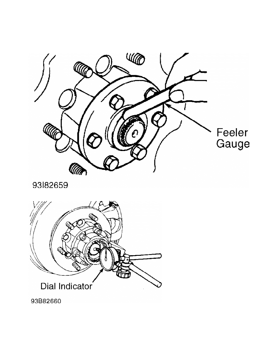
Fig. 3: Measuring Axle Shaft End Play (Montero)
Courtesy of Mitsubishi Motor Sales of America.
Fig. 4: Measuring Axle Shaft End Play (Pickup & Ram-50)
Courtesy of Mitsubishi Motor Sales of America.
DIFFERENTIAL CARRIER ASSEMBLY

Removal
1) Raise and support vehicle. Drain gear oil. Support
differential carrier. Remove the drive axles and inner shaft. See
DRIVE AXLES and INNER SHAFT & BEARING under REMOVAL & INSTALLATION.
Place alignment mark on drive shaft and pinion companion flange for
reassembly reference.
2) Remove drive shaft. Remove differential mounting brackets
at differential and frame. See Fig. 1. Disconnect front crossmember
from frame. Remove differential carrier assembly and front
crossmember. Remove differential carrier from front crossmember.
Installation
To install, reverse removal procedure. Align marks on drive
shaft and pinion companion flange.
INNER SHAFT & BEARING
Removal
Remove right drive axle. See DRIVE AXLES under REMOVAL &
INSTALLATION. Using slide hammer, remove inner shaft from differential
carrier. If dust seal replacement is required, pry dust seal from
housing tube assembly using a screwdriver. See Fig. 1. To remove
bearing, bend outer area of dust cover inward on inner shaft. Press
shaft out of bearing. Remove dust cover from shaft.
Inspection
Inspect inner shaft for damaged splines or threads. Inspect
bearing for roughness or damage.
Installation
1) Install housing tube. Using Seal Installer (MB990955) and
Handle (C-4171), install new dust seal in housing tube. Dust seal must
be even with housing tube. Coat seal lip with grease.
2) Using a pipe with O.D. of 2.95" (74.3 mm), wall thickness
of .16" (4.0 mm) and overall length of 1.97" (50.0 mm), install dust
cover on shaft. Coat inside of dust cover with grease. Press bearing
on shaft. Install new circlip on inner shaft. Carefully drive inner
shaft into differential. DO NOT damage oil seal. To complete
installation, reverse removal procedure.
OVERHAUL
DRIVE AXLES & BEARINGS
NOTE: References to BJ and DOJ refer to Birfield Joint and Double
Offset Joint, respectively.
Disassembly
1) Remove boot bands. Remove circlip from DOJ outer race.
Separate drive axle from DOJ outer race. Remove balls from DOJ cage.
Remove DOJ cage from DOJ inner race in direction of BJ. See Fig. 5.
2) Remove snap ring from drive axle shaft. Remove DOJ inner
race from shaft. Remove circlip from shaft. Wrap tape around splines
of shaft to prevent boot damage during removal. Remove DOJ boot. Note
size of boot. Remove dust cover from shaft. Move boot protector toward
BJ side of shaft and remove. Remove BJ boot.
CAUTION: Drive axle and BJ are serviced as a unit. DO NOT attempt to
disassemble BJ and drive axle.
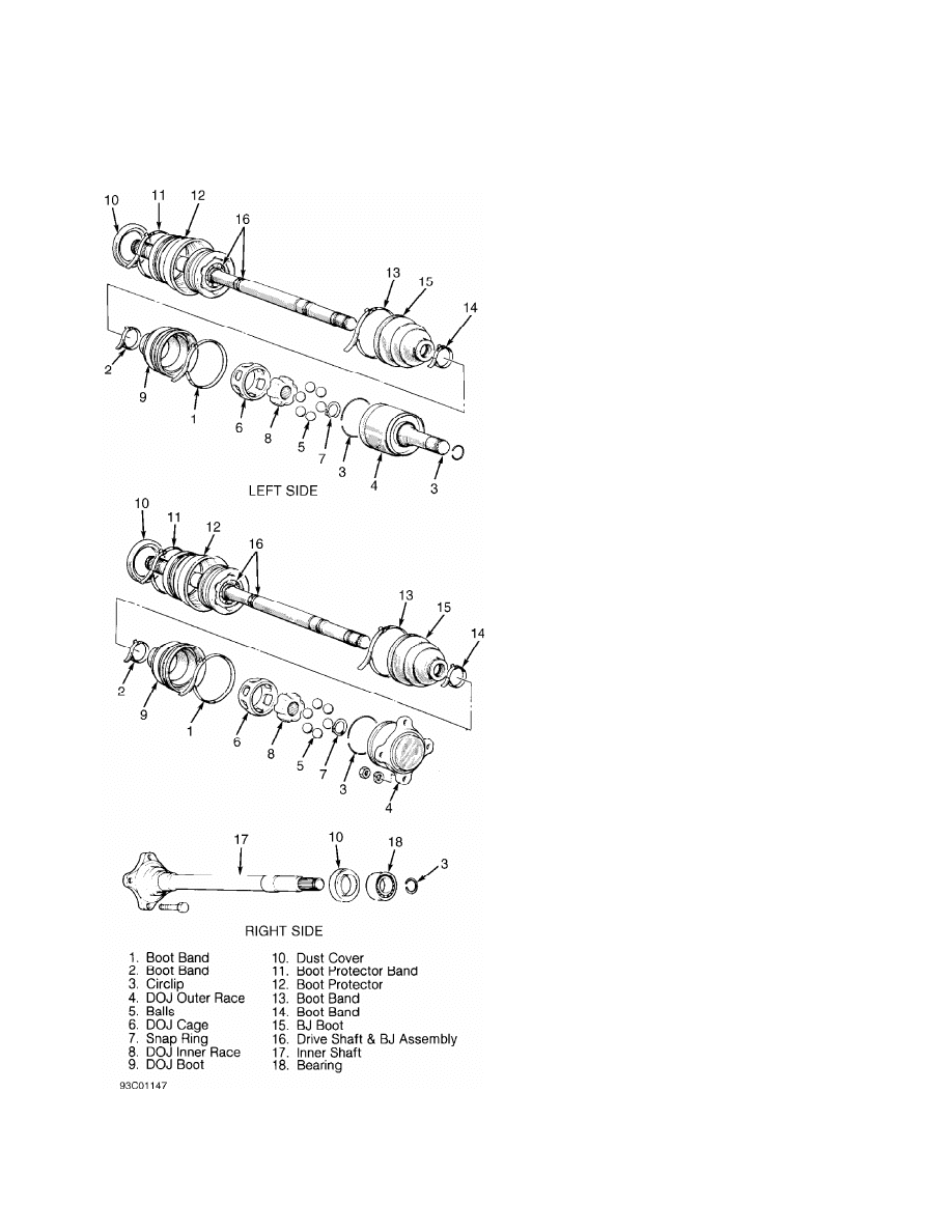
Fig. 5: Exploded View Of Drive Axles
Courtesy of Mitsubishi Motor Sales of America.
Reassembly
1) Coat shaft with light coat of grease. Wrap splines with

tape. Install BJ boot, bands and DOJ boot on shaft. Ensure correct
size boot is installed in proper location.
2) Pack proper amount of grease in the BJ and BJ boot. See
CV JOINT GREASE CAPACITY table. Boot bands must be installed so lever
is pulled toward rear of vehicle when band is tightened.
3) Place DOJ cage on shaft with smaller diameter installed
first. Install circlip, DOJ inner race and snap ring on shaft. Apply
grease to DOJ inner race and cage. Install balls into cage. Apply
proper amount of grease to outer DOJ race. See CV JOINT GREASE
CAPACITY table. Install shaft into DOJ outer race. Install circlip.
4) Place DOJ boot over DOJ outer race. Install boot bands so
lever is pulled toward rear of vehicle when band is tightened. Adjust
DOJ boot bands to have proper distance between center line of boot
bands. See BOOT BAND SPECIFICATIONS table. This distance is necessary
to control air in DOJ boot. Tighten boot bands. Install boot protector
and band. Install dust cover on shaft.
CV JOINT GREASE CAPACITY TABLE
Application Ozs. (g)
BJ Boot
Montero ............................................ ( 1)
Pickup & Ram-50 .................................... ( 1)
DOJ Outer Race
Montero ...................................... 3.5 (100)
Pickup & Ram-50 .............................. 3.9 (110)
(1) - Boots, bands and grease are packaged as a kit.
No specifications given by manufacturer.
BOOT BAND SPECIFICATIONS TABLE
Application In. (mm)
All Models ................... 3.03-3.27 (76.9-83.0)
DIFFERENTIAL ASSEMBLY
Disassembly
1) Remove the differential carrier from vehicle. See
DIFFERENTIAL CARRIER ASSEMBLY under REMOVAL & INSTALLATION. Remove
cover. Mark bearing caps for reassembly reference. Remove bearing
caps. Remove differential case assembly from carrier.
CAUTION: Ensure adjusting spacers, bearing caps, gears and side
bearings are marked for reassembly reference. Components
must be installed in original location.
2) Using bearing puller, remove differential case side
bearings. Loosen ring gear retaining bolts in diagonal sequence.
Remove ring gear. Remove drive pinion shaft lock pin from ring gear
side. Remove pinion shaft and pinion gears. Remove side gears and
thrust spacers.
Drive Pinion Removal
Remove pinion flange nut. Scribe alignment mark on pinion
companion flange and drive pinion. Remove flange. Using soft-faced
hammer, drive out pinion. Remove rear bearing and oil seal from
carrier. Remove rear adjusting shim from pinion. See Fig. 1. Press
front bearing from pinion. Remove front adjusting shim and spacer from
pinion.
Cleaning & Inspection
Use cleaning solvent to rinse gears and components. Check
bearings for wear or discoloration. Check gear carrier for cracks or
damage. Check pinion, side gear and flange splines for excessive wear.
Check ring gear, pinion and side gears for wear or damage. Replace
components as necessary.
Reassembly & Adjustments
1) Place side gear thrust spacers behind side gears in
original position. Assemble side gears in differential case. Install
pinion gears and washers. Rotate pinion gears to mesh with side gears.
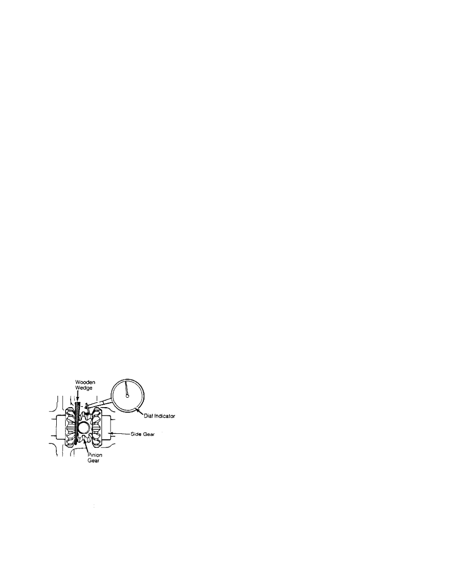
2) Install pinion shaft without lock pin. Check pinion and
side gear backlash. Install wooden wedge to lock side gears. Using
dial indicator, measure gear backlash. See Fig. 6.
3) Backlash must be within specification. See PINION & SIDE
GEAR BACKLASH SPECIFICATIONS table. Adjust backlash by using different
side gear spacers. Ensure both sides are equally shimmed. If backlash
cannot be adjusted within specifications, replace side and pinion
gears as matched set.
4) Install pinion shaft lock pin. Using a punch, securely
stake lock pin in 2 places. Ensure adhesive is removed from ring gear
mounting bolts and gear mounting surface. Clean internal threads with
tap.
5) Install ring gear on differential case. Ensure alignment
marks on differential case and ring gear are aligned. Apply Loctite
271 to bolts and install bolts. Tighten bolts alternately in diagonal
sequence to specification. See TORQUE SPECIFICATIONS table.
PINION & SIDE GEAR BACKLASH SPECIFICATIONS TABLE
Application In. (mm)
Standard ............................ .003 (.08)
Wear Limit .......................... .008 (.20)
Fig. 6: Checking Pinion & Side Gear Backlash
Courtesy of Mitsubishi Motor Sales of America.
Drive Pinion Depth
1) Install pinion bearing races in carrier housing. Ensure
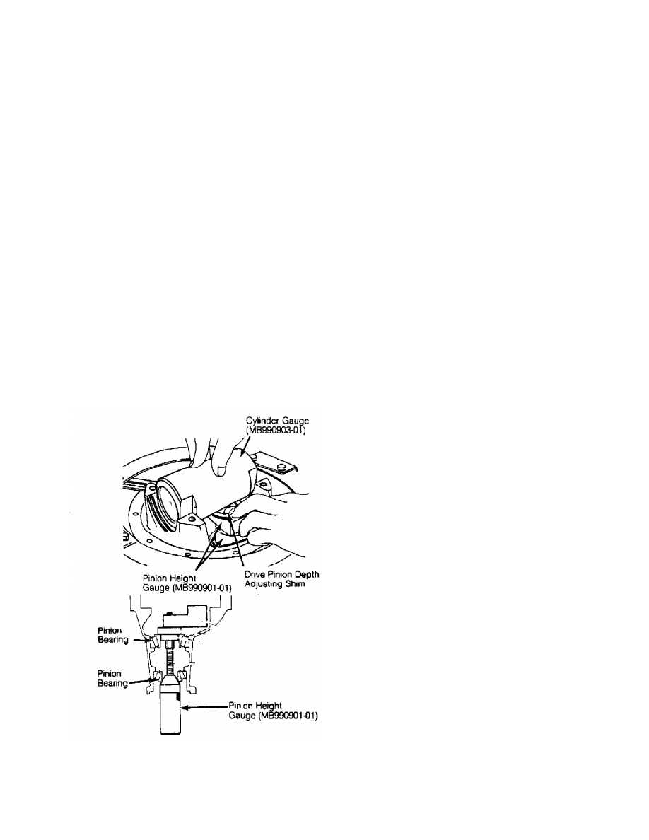
races are fully seated. Install Pinion Height Gauge (MB990901-01) with
pinion bearings. See Fig. 7. DO NOT install oil seal.
2) Using INCH-lb. torque wrench, measure pinion rotating
torque. Gradually tighten pinion height gauge to increase rotating
torque to proper specification. See PINION ROTATING TORQUE
SPECIFICATIONS table. Install Cylinder Gauge (MB990903-01). Ensure
flat areas are aligned and gauge contacts carrier bearing bores
firmly. See Fig. 7.
3) Select adjusting shim with same thickness as gap between
cylinder gauge and pinion height gauge. Use minimum amount of
adjusting shims. Install selected adjusting shims between drive pinion
gear and rear drive pinion bearing. Using Bearing Installer (MB990802-
01), install rear pinion bearing.
PINION ROTATING TORQUE SPECIFICATIONS TABLE
Application INCH Lbs. (N.m)
Oil Seal Not Installed
With Lubrication ........... 1.3-2.2 (.15-.25)
Without Lubrication ........ 2.6-4.3 (.30-.50)
Oil Seal Installed
With Lubrication ........... 3.1-3.9 (.35-.45)
Without Lubrication ........ 4.3-6.1 (.50-.70)
Fig. 7: Setting Drive Pinion Depth
Courtesy of Mitsubishi Motor Sales of America.
Drive Pinion Preload
1) Install drive pinion in differential carrier. Install

spacer, pinion front shim(s) and front pinion bearing. DO NOT install
oil seal at this time. Install pinion companion flange, washer and
retaining nut. Tighten nut to 137 ft. lbs. (190 N.m).
2) Using INCH-lb. torque wrench, check pinion rotating torque
without pinion oil seal. See PINION ROTATING TORQUE SPECIFICATIONS
table. Adjust rotating torque by replacing drive pinion front shims or
spacer. Once correct rotating torque is obtained, install oil seal.
Coat seal lip with grease.
3) Install pinion flange so alignment marks are correct.
Apply light coat of grease to flange washer contact area. Install new
retaining nut. Check pinion rotating torque with pinion oil seal
installed. Rotating torque must be within proper specification. See
PINION ROTATING TORQUE SPECIFICATIONS table.
Side Bearing Installation
1) Using Bearing Installer (MB990802-01), install bearings on
differential case. Select 2 side bearing adjusting shims thinner than
those removed. Shims must be equal in thickness on both sides. Install
shims on each side of case assembly. Install case assembly in
differential carrier housing.
2) Push case assembly fully to one side of carrier. Using 2
feeler gauges (feeler gauges 180 degrees opposed), measure clearance
between carrier and side bearing. Remove shims from one side of
differential carrier.
3) Measure thickness of shims removed. Add .002" (.05 mm) to
50% of measured clearance and then add thickness measurement of
removed shim. This is thickness of new shim that should be installed
on each side of case. Install equal thickness shims on each side of
case assembly.
NOTE: Ensure zero clearance exists between gear carrier and
adjusting shim.
4) Install side bearing shims and differential case assembly
in differential carrier. Using brass drift, tap shims to fit them to
side bearing outer race. Install bearing caps. Tighten bolts to
specification. See TORQUE SPECIFICATIONS table. Check ring gear
backlash.
Ring Gear Backlash
1) Lock drive pinion in place. Using dial indicator, check
ring gear backlash at heel of ring gear tooth. Measure at 4 locations
of ring gear. Gear backlash should be .004-.006" (.10-.15 mm).
2) If backlash is not within specification, change side
bearing adjusting shims and recheck backlash. See GEAR TOOTH CONTACT
PATTERNS article in GENERAL INFORMATION. Check gear tooth contact
using Prussian Blue.
CAUTION: When changing shims, total thickness of all shims must
remain constant to ensure correct bearing preload.
Ring Gear Runout
Using dial indicator, measure runout at back side of ring
gear. Runout should be .002" (.05 mm). If runout is excessive, change
ring gear-to-differential case mounting position. Ensure ring gear
mounting bolts are tightened to correct specification. Recheck runout.
Install cover and gasket.
TORQUE SPECIFICATIONS
TORQUE SPECIFICATIONS TABLE

Application Ft. Lbs. (N.m)
Brake Caliper Bolt ......................... 58-72 (79-98)
Carrier-To-Housing Tube Bolt ............... 58-72 (79-98)
Cover Bolt ................................. 11-16 (15-22)
Drain Plug ................................. 43-51 (58-69)
Drive Shaft Flange Bolt .................... 36-43 (49-58)
Fill Plug .................................. 29-43 (39-58)
Front Crossmember Bolt .................... 72-87 (98-118)
Hub Cover Bolt ............................. 13-25 (18-34)
Knuckle-To-Ball Joint Nut
Upper .................................... 43-65 (58-88)
Lower ................................. 87-130 (118-176)
Mounting Bracket-To-Frame Bolt ............ 58-80 (79-108)
Mounting Bracket-To-Housing Tube Bolt ...... 58-72 (79-98)
Pinion Flange Nut ...................... 137-159 (186-220)
Right Drive Axle-To-Inner Shaft Bolt ....... 36-43 (49-58)
Ring Gear-To-Case Bolt ..................... 58-65 (79-88)
Side Bearing Cap Bolt ...................... 40-47 (54-64)
Tie Rod-To-Knuckle Nut ........................... 33 (45)
Wheel Lug Nuts
Montero ................................. 72-87 (98-118)
Pickup & Ram-50 ....................... 87-101 (118-137)
INCH Lbs. (N.m)
Undercover-To-Frame Bolts (Montero) .... 84-108 (9.5-12.2)
Wyszukiwarka
Podobne podstrony:
The Differences and Similarities of Pneumonia and Tuberculosi
07 SUSPENSION AND AXLE
Harrison C White Status Differentiation and the Cohesion of Social Network(1)
07 SUSPENSION AND AXLE
THE POLITICS OF DIFFERENCE AND COMMUNITY AND THE ETHIC OF UNIVERSALISM
2002 09 Creating Virtual Worlds with Pov Ray and the Right Front End
Albert, Buzan Functional differentiation and sectors between Sociology and International Relation
11 drive shaft and front axle
Complex Numbers and Ordinary Differential Equations 36 pp
Gender and Racial Ethnic Differences in the Affirmative Action Attitudes of U S College(1)
Mathematics HL paper 3 series and differential equations 001
Mathematics HL paper 3 series and differential equations
Differences?tween islamic?nks and conventional?nks
PRACTICAL SPEAKING EXERCISES with using different grammar tenses and constructions, part Ix
Back Post Double Crochet (BPdc) and Front Post Double Crochet (FPdc)
Equality And Difference
więcej podobnych podstron