
VERSA 2000 (RT1)
SERVICE AND REFERENCE MANUAL
SOLD BY laptopia2005 DO NOT RESELL!!
SOLD BY laptopia2005 DO NOT RESELL!!

PROPRIETARY NOTICE AND LIABILITY DISCLAIMER
The information disclosed in this document, including all designs and related materials, is
the valuable property of NEC Corporation (NEC) and/or its licensors. NEC and/or its
licensors, as appropriate, reserve all patent, copyright and other proprietary rights to this
document, including all design, manufacturing, reproduction, use, and sales rights thereto,
except to the extent said rights are expressly granted to others.
The NEC product(s) discussed in this document are warranted in accordance with the terms
of the Warranty Statement accompanying each product. However, actual performance of
each such product is dependent upon factors such as system configuration, customer data,
and operator control. Since implementation by customers of each product may vary, the
suitability of specific product configurations and applications must be determined by the
customer and is not warranted by NEC.
To allow for design and specification improvements, the information in this document is
subject to change at any time, without notice. Reproduction of this document or portions
thereof without prior written approval of NEC is prohibited.
FastFacts, and NEC SVGA, are U.S. trademarks of NEC Technologies, Inc.
All other product, brand, or trade names used in this publication are the trademarks or registered
trademarks of their respective trademark owners.
SOLD BY laptopia2005 DO NOT RESELL!!
SOLD BY laptopia2005 DO NOT RESELL!!

Preface ............................................................................................................................. vii
Abbreviations .................................................................................................................. ix
Section 1 Technical Information
Hardware Overview......................................................................................................... 1-2
Liquid Crystal Display (LCD) .................................................................................. 1-3
System Board ........................................................................................................... 1-3
Battery Pack ............................................................................................................. 1-4
CMOS Battery.......................................................................................................... 1-4
Bridge Battery .......................................................................................................... 1-4
PCMCIA Slots.......................................................................................................... 1-4
Keyboard .................................................................................................................. 1-4
NEC VersaGlide....................................................................................................... 1-5
System Memory............................................................................................................... 1-5
Memory Map............................................................................................................ 1-6
System Video................................................................................................................... 1-7
Parallel Interface.............................................................................................................. 1-11
Serial Interface................................................................................................................. 1-11
NEC Versa 2000 Series Chip Set .................................................................................... 1-11
System Logic ............................................................................................................ 1-12
Flash ROM ............................................................................................................... 1-12
ROM BIOS........................................................................................................ 1-12
Peripheral Controller ................................................................................................ 1-13
VGA Controller........................................................................................................ 1-13
Video Controller Architecture........................................................................... 1-13
Diskette Controller, Serial Interface, Parallel Interface ........................................... 1-14
Keyboard Controller................................................................................................. 1-14
PCMCIA Controller ................................................................................................. 1-14
I/O Addressing ......................................................................................................... 1-15
Interrupt Controllers ................................................................................................. 1-16
Power Management Overview ........................................................................................ 1-17
System Power Management ..................................................................................... 1-17
Local Power Management........................................................................................ 1-17
Plug and Play................................................................................................................... 1-18
Specifications .................................................................................................................. 1-19
Section 2 Setup and Operation
SOLD BY laptopia2005 DO NOT RESELL!!
SOLD BY laptopia2005 DO NOT RESELL!!

Unpacking the System ..................................................................................................... 2-1
Setup ................................................................................................................................ 2-1
Cable Connections.................................................................................................... 2-2
Operating Controls .......................................................................................................... 2-3
LEDs......................................................................................................................... 2-4
Function Keys (Fn Keys).......................................................................................... 2-5
CMOS Clear Switch and Keyboard Switch ............................................................. 2-6
Smart Power Switch ................................................................................................. 2-7
Power-on Self-Test (Post) ............................................................................................... 2-7
POST Errors ............................................................................................................. 2-8
System Parameters........................................................................................................... 2-9
Auto Setup................................................................................................................ 2-9
Accessing Auto Setup .............................................................................................. 2-9
Auto Setup Keys ............................................................................................... 2-10
Auto Setup Parameter Options ........................................................................................ 2-11
Parameter Descriptions ............................................................................................ 2-12
Comms .............................................................................................................. 2-12
Drives ................................................................................................................ 2-12
Keyboard ........................................................................................................... 2-12
Power ................................................................................................................ 2-13
System ............................................................................................................... 2-13
Time/Date.......................................................................................................... 2-14
Using Auto Setup to Select Parameters........................................................................... 2-14
Security Options .............................................................................................................. 2-15
System Password...................................................................................................... 2-15
Using the System Password .............................................................................. 2-15
Keyboard Lock Hotkey ............................................................................................ 2-16
NEC Utilities ................................................................................................................... 2-17
BIOS Update Utility (BUU) ..................................................................................... 2-17
Precautions ........................................................................................................ 2-17
Downloading the Update Utility ....................................................................... 2-18
Using the Update Utility ................................................................................... 2-18
Menu Functions................................................................................................. 2-20
Power Sources ................................................................................................................. 2-24
AC Adapter .............................................................................................................. 2-24
Battery Power ........................................................................................................... 2-25
Recharging the Battery Pack ............................................................................. 2-26
SOLD BY laptopia2005 DO NOT RESELL!!
SOLD BY laptopia2005 DO NOT RESELL!!

Replacing the Battery Pack.............................................................................................. 2-26
Saving Battery Power ............................................................................................... 2-27
Automatic Power-Saving Features .................................................................................. 2-28
Power Saving Levels ................................................................................................ 2-28
Active Mode...................................................................................................... 2-28
Suspend Mode................................................................................................... 2-28
Section 3 Illustrated Parts Breakdown
Appendix A Connector Locations and Pin Assignments
List of Figures
1-1
Versa 2000 Series (Right Side View) ............................................................... 1-1
1-2
Versa 2000 Series (Left Side View).................................................................. 1-2
1-3
Versa 2000 Series (Rear View)......................................................................... 1-3
2-1
Power and I/O Connector Locations ................................................................. 2-2
2-2
Control and Switch Locations........................................................................... 2-3
2-3
CMOS Clear and Keyboard Switch Locations ................................................. 2-6
2-4
Connecting the AC Adapter .............................................................................. 2-25
2-5
Battery Release Latch Location......................................................................... 2-26
2-6
Battery Pack Replacement ................................................................................ 2-27
3-1
Illustrated Parts Breakdown .............................................................................. 3-4
A-1
System Board Connector Locations .................................................................. A-1
List of Tables
1-1
Versa 2000 Series Memory Map....................................................................... 1-6
1-2
CRT Display Mode (CRT only)........................................................................ 1-7
1-3
LCD Display Modes (640 x 480 TFT, Simultaneous CRT) ............................. 1-9
1-4
LCD Display Modes (640 x 480 DSTN, Simultaneous CRT).......................... 1-10
1-5
Versa 2000 Series Chip Types and Technologies ............................................. 1-11
1-6
Versa 2000 Series I/O Address Map ................................................................. 1-15
1-7
Versa 2000 Series Interrupt Level Assignments ............................................... 1-16
1-8 Specifications ....................................................................................................
1-19
SOLD BY laptopia2005 DO NOT RESELL!!
SOLD BY laptopia2005 DO NOT RESELL!!

2-1
I/O Connector Descriptions............................................................................... 2-2
2-2
Control and Switch Functions........................................................................... 2-4
2-3 FnKey
Operations .............................................................................................
2-5
2-4
POST Error Messages ....................................................................................... 2-8
2-5
Auto Setup Key Functions ................................................................................ 2-10
2-6
Auto Setup Parameter Options.......................................................................... 2-11
2-7
Automatic Power-Saving Features.................................................................... 2-28
3-1
Versa 2000 Series Field-Replaceable Parts....................................................... 3-1
3-2
Option and Documentation Part Numbers ........................................................ 3-5
A-1
System Board Connectors ................................................................................. A-1
A-2
Keyboard/Mouse Connector Pin Assignments ................................................. A-2
A-3
Serial Port Connector Pin Assignments ............................................................ A-3
A-4
CRT Connector Pin Assignments ..................................................................... A-3
A-5
Parallel Printer Pin Assignments....................................................................... A-4
A-6
Docking Connector Pin Assignments ............................................................... A-5
A-7 Power
Connector...............................................................................................
A-9
A-8
Hard Disk Drive Connector .............................................................................. A-10
SOLD BY laptopia2005 DO NOT RESELL!!
SOLD BY laptopia2005 DO NOT RESELL!!

Preface
This service and reference manual contains the technical information necessary to set up,
and maintain the NEC Versa™ 2000 Series Notebook systems. It also provides hardware
and interface information for users who need an overview of the computer system design.
The manual is written for NEC-trained customer engineers, system analysts, service center
personnel, and dealers.
Please refer to the training module provided on CD-ROM for disassembly/assembly
procedures.
The manual is organized as follows:
Section 1
Technical Information, provides an overview of the hardware and interface
components. System specifications are listed including computer dimensions, weight,
environment, safety compliance, power consumption, and system memory specifications.
Section 2
Setup and Operation, takes the user from unpacking to setup and operation.
The section includes a description of operating controls, setting parameters and accessing
the NEC bulletin board system (BBS).
Section 3
Illustrated Parts Breakdown (IPB), provides an exploded-view diagram of
the Versa 2000 series system and part numbers.
Appendix A
Connector Locations and Pin Assignments, provides a list of the main
board internal connector pin assignments and a list of external pin assignments.
An Index is included for convenience.
SOLD BY laptopia2005 DO NOT RESELL!!
SOLD BY laptopia2005 DO NOT RESELL!!

Abbreviations
A ampere
AC alternating
current
AT
advanced technology
(IBM
PC)
BBS
Bulletin Board System
BCD binary-coded
decimal
BCU
BIOS Customized Utility
BIOS
basic input/output system
bit binary
digit
bpi
bits per inch
bps
bits per second
BUU
BIOS Upgrade Utility
C centigrade
Cache
high-speed buffer storage
CAM
constantly addressable memory
CAS
column address strobe
CD-ROM compact
disk-ROM
CGA
Color Graphics Adapter
CGB
Color Graphics Board
CH channel
clk clock
cm centimeter
CMOS
complementary metal oxide
semiconductor
COM communication
CONT contrast
CPGA
ceramic pin grid array
CPU
central processing unit
CRT cathode-ray
tube
DAC digital-to-analog
converter
DACK DMA
acknowledge
DC direct
current
DIP
dual in-line package
DLAB
Divisor Latch Address bit
DMA
direct memory access
DMAC DMA
controller
DOS
disk operating system
SOLD BY laptopia2005 DO NOT RESELL!!
SOLD BY laptopia2005 DO NOT RESELL!!

DRAM dynamic
RAM
DTE
data terminal equipment
ECC
error checking and correction
EDS
error detecting system
EGA
Enhanced Graphics Adapter
EMS
Expanded Memory
Specification
EPP
enhanced parallel port
EPROM
erasable and programmable
ROM
EVGA
Enhanced Video Graphics
Array
F Fahrenheit
FAX facsimile
transmission
FCC
Federal Communications
Commission
FG frame
ground
FM frequency
modulation
Fn Function
FRU field-replaceable
unit
GB gigabyte
GND ground
HDD hard
diskdrive
HEX hexadecimal
HGA
Hercules Graphics Adapter
Hz hertz
IC integrated
circuit
ID identification
IDE
intelligent device electronics
IDTR
interrupt descriptor table register
IMR
Interrupt Mask register
in. inch
INTA interrupt
acknowledge
IPB
illustrated parts breakdown
IRR
Interrupt Request register
ISA
Industry Standard Architecture
ISR
In Service register
I/O input/output
IPC
integrated peripheral controller
ips
inches per second
IRQ interrupt
request
SOLD BY laptopia2005 DO NOT RESELL!!
SOLD BY laptopia2005 DO NOT RESELL!!

K kilo
(1024)
k kilo
(1000)
KB kilobyte
kg kilogram
kHz kilohertz
kV kilovolt
lb pound
LDTR
local descriptor table register
LED light-emitting
diode
LSB least-significant
bit
LSI large-scale
integration
M mega
mA milliamps
max maximum
MB megabyte
MDA
Monochrome Display Adapter
MFM
modified frequency modulation
Mhz megahertz
mm millimeter
ms millisecond
MSB most-significant
bit
NASC
National Authorized Service
Center
NC not
connected
NDP
numeric data processor
NMI Non-maskable
Interrupt
ns nanosecond
NSRC
National Service Response
Center
PAL
programmable array logic
PC personal
computer
PCB
printed circuit board
PFP
plastic flat package
PIO parallel
input/output
pixel picture
element
PJQFP
plastic J-lead quad flat pack
PLCC
plastic lead chip carrier
PLL
phase lock loop
p-p peak-to-peak
SOLD BY laptopia2005 DO NOT RESELL!!
SOLD BY laptopia2005 DO NOT RESELL!!

PPI
programmable peripheral
interface
PROM programmable
ROM
QFP
quad flat pack
RAM random-access
memory
RAMDAC RAM digital-to-analog
RAS
row address strobe
RGB
red green blue
RGBI
red green blue intensity
ROM read-only
memory
rpm
revolutions per minute
R read
RTC real-time
clock
R/W read/write
S slave
SCSI
Small Computer System Interface
SDLC
Synchronous Data Link Control
SG signal
ground
SIMM
single inline memory module
SQFP
silver quad flat package
SVGA
Super Video Graphics Array
SW switch
TAC
Technical Assistance Center
TCP
Thin chip package
TQFP
Thin-quad flat package
TSC
Technical Support Center
TTL transistor/transistor
logic
tpi
tracks per inch
UART
universal asynchronous receiver/transmitter
V volt
Vdc
volts, direct current
VESA
video electronics standards
association
VFO
variable frequency oscillator
VGA
Video Graphics Array
VLSI
very large-scale integration
VRAM virtual
RAM
W watt
W write
SOLD BY laptopia2005 DO NOT RESELL!!
SOLD BY laptopia2005 DO NOT RESELL!!

µ
f microfarad
µ
PD microprocessor
µ
s microsecond
Ω
ohm
SOLD BY laptopia2005 DO NOT RESELL!!
SOLD BY laptopia2005 DO NOT RESELL!!
Section 1
Technical Information
The NEC Versa 2000 series computers integrate the Intel
®
486 DX4-75 chip. The systems
offer a unique transportable unit in the following configurations:
!"
NEC Versa 2000C
75-MHz CPU, 350-MB hard disk drive, 9.5-inch thin-film
transistor (TFT) color LCD, 4-MB standard RAM, 1-MB video memory, 256-KB
ROM, no modem
!"
NEC Versa 2000C
75-MHz CPU, 350-MB hard disk drive, 9.5-inch thin-film
transistor (TFT) color LCD, 8-MB standard RAM, 1-MB video memory, 256-KB
ROM, 14.4K bps data fax/modem
!"
NEC Versa 2000C
75-MHz CPU, 540-MB hard disk drive, 9.5-inch thin-film
transistor (TFT) color LCD, 8-MB standard RAM, 1-MB video memory, 256-KB
ROM, 14.4K bps fax/modem
!"
NEC Versa 2000D
75-MHz CPU, 350-MB hard disk drive, 10.4-inch Dual-
scan Super Twisted Nematic (DSTN) color LCD, 4-MB standard RAM, 1-MB
video memory, 256-KB ROM, no modem
Figure Section 2-1 and Figure Section 2-2 show system features.
Figure Section 2-1
Versa 2000 Series (Right Side View)
SOLD BY laptopia2005 DO NOT RESELL!!
SOLD BY laptopia2005 DO NOT RESELL!!
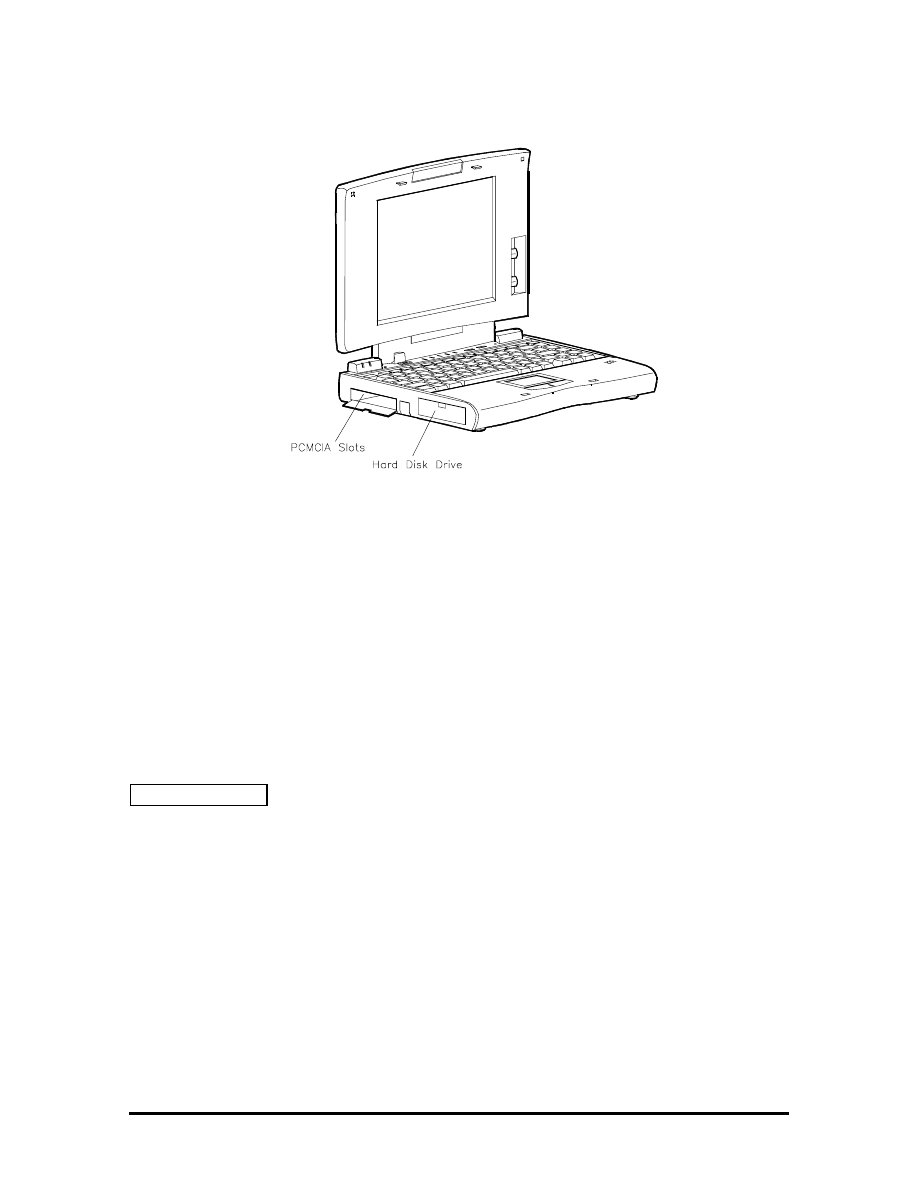
Figure Section 2-2 Versa 2000 Series (Left Side View)
HARDWARE OVERVIEW
The base unit includes a color LCD panel, a 2 1/2-inch 350-MB, or 540-MB hard disk
drive, a 3 1/2-inch, 1.44-MB diskette drive, a battery pack, and a PS/2 compatible 83-key
keyboard. A 79-key keyboard is used for U.K. and Germany.
Two memory cards slot are available for the addition of a 4-, 8- or 16-MB capacity
memory card. Two Personal Computer Memory Card International Association (PCMCIA)
card slots, supported by the Cirrus Logic CL-PD6720 PCMCIA controller, allow for the
addition of either two PCMCIA Type 1/Type II cards or one PCMCIA Type III card.
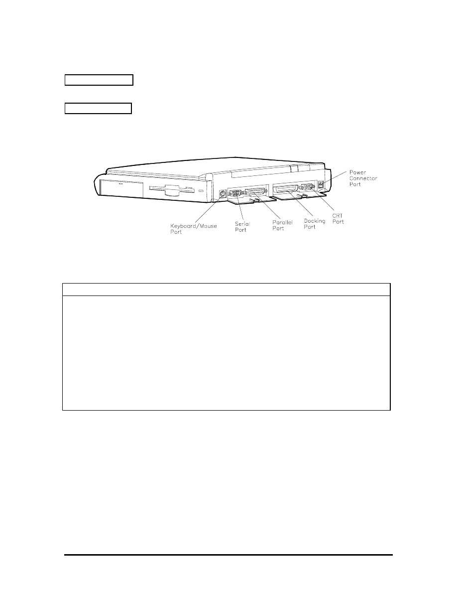
Figure Section 2-3 shows the standard I/O interface ports on the system's rear panel. These
include one 6-pin shared PS/2-style keyboard/mouse port, one 9-pin (RS-232C) serial port,
one 25-pin enhanced printer (parallel) port, one docking connector, one 15-pin Super VGA
CRT port, and one 3-pin power connector port.
SOLD BY laptopia2005 DO NOT RESELL!!
SOLD BY laptopia2005 DO NOT RESELL!!
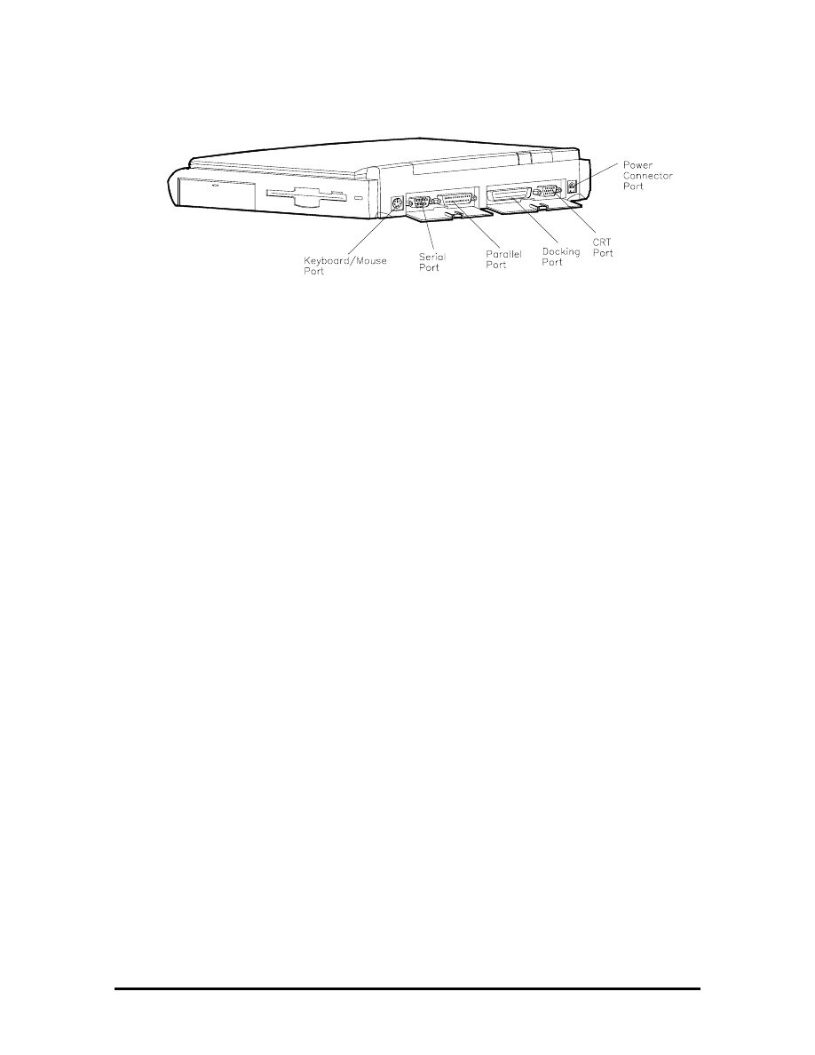
Figure Section 2-3
Versa 2000 Series (Rear View)
Liquid Crystal Display (LCD)
The system integrates a built-in LCD. The LCD supports VESA Local (VL) bus video. The
LCD operates with the Chips & Technologies 65545B1-5 VGA controller. The controller
supports Super VGA. For more information on the 65545B1-5 VGA controller, read the
description provided in the Versa 2000 Series Chip Set subsection.
The Versa 2000 series system features the following types of LCDs.
!"
TFT — 9.5-inch thin-film transistor backlit color LCD, 0.3 mm dot pitch, 12-bit
digital interface, 640 x 480 resolution, 4,096 colors, (64K colors on an external
CRT).
!"
DSTN — 10.4-inch dual-scan super twisted nematic color LCD, 0.3 mm dot
pitch, 12-bit digital interface, 600 x 480 resolution, (64K colors on an external
CRT).
In addition, the CRT port on the system's rear panel allows the user to connect an optional
monochrome or color external display to the system. The computer supports the LCD and
external display simultaneously.
Power-saving features for controlling the LCD's backlighting include the ROM-based hot
key Fn F5, and Auto Setup power management settings. See Section 2, Setup and
Operation, for information on using these settings. In addition, the automatic LCD status
sense feature conserves the backlight. When the LCD is closed the backlight shuts off,
saving battery power.
SOLD BY laptopia2005 DO NOT RESELL!!
SOLD BY laptopia2005 DO NOT RESELL!!

System Board
The system board (G8TZL) is the primary component in the system. It contains I/O
subsystems and houses the Intel
®
486 DX4-75 chip (75 Mhz internal, 50 Mhz external).
The chip controls important functions including power management, direct drive bus
interface and memory management.
System board specifications are listed in Table Section 2-8 at the end of this section.
Battery Pack
The system uses a rechargeable lithium-ion (Li-ION) battery as its transient power source.
The battery pack installs in the compartment next to the diskette drive assembly. The
battery uses 14.4 volts with a 2700 mAh capacity.
The battery pack powers the Versa 2000 for up to approximately four hours under power
management, and two hours without power management. In addition, the battery pack lets
the user know how much battery power is available via the LEDs on the front of the
system, or the battery gas gauge in Windows.
When battery power is getting low, connect the AC adapter to a wall outlet and recharge
the battery. It takes 1.6 hours to recharge the battery pack when the system is powered off.
It takes 6 to 9 hours to recharge the battery while the system is powered on.
CMOS Battery
The lithium battery (3.6 Volts, 1000 mAh capacity) is connected to CN17A on the system
board. It provides battery backup and prevents data loss in the system’s complementary
metal oxide semiconductor (CMOS) RAM. This memory area contains information on the
system’s configuration like date, time, drives, and memory. The CMOS battery lasts
approximately two years.
Bridge Battery
The bridge battery saves the memory contents and system status for up to 5 minutes while
in Suspend mode. It is connected to the system board via CN 13. The AC adapter maintains
voltage in the bridge battery when the system is powered on or off. The bridge battery
provides 10 Volts, 30 mAH.
PCMCIA Slots
The Versa 2000 provides a 3.3 volt interface for either two Type I/Type II PCMCIA cards,
or one Type III PCMCIA card.
SOLD BY laptopia2005 DO NOT RESELL!!
SOLD BY laptopia2005 DO NOT RESELL!!

Keyboard
The built-in, 83-key keyboard (U.S) or 79-key keyboard (UK and Germany) uses the
standard QWERTY format. The keyboard provides 12 function keys and 8 cursor control
keys, with an Fn key for ROM-based key functions. The numeric keypad is embedded in
the standard key layout.
NEC VersaGlide
The NEC VersaGlide is a built-in mechanism that functions as the system’s mouse. It
controls the on-screen pointer (cursor). To use the VersaGlide, glide your finger across the
NEC VersaGlide pad, and the cursor follows. The buttons on either side of the NEC
VersaGlide allow the user to select or deselect menu items. Double-tap is also supported on
the VersaGlide pad.
The NEC VersaGlide is the system's default pointing device unless a PS/2 mouse is
installed. If an external mouse is installed, then the NEC VersaGlide is deactivated. A
serial mouse is not supported.
SYSTEM MEMORY
The system board provides either 4- or 8-MB of standard random access memory (RAM).
Base memory is 640 KB and extended memory is 3072 or 7168 KB (interleaved),
depending on the system model.
Optional memory cards with a value of 4-, 8-, or 16-MB can be added to increase system
memory up to a maximum of 36- or 40-MB. In addition, 256 KB of read-only memory
(ROM), 1 x 28F020, enables the system BIOS to be flashed.
SOLD BY laptopia2005 DO NOT RESELL!!
SOLD BY laptopia2005 DO NOT RESELL!!

Memory Map
The system supports system and video shadowing, both controlled through complementary
metal oxide semiconductor (CMOS). The system supports BIOS as a cacheable area with
write protection. Table Section 2-1 lists the system's memory map.
To view a more complete breakdown, and to determine available space for the addition of
drivers etc., type
MSD at the DOS prompt and press Enter.
Table Section 2-1 Versa 2000 Series System Memory Map
Memory Space
Size
Function
017FFFFFh-
01400000h
24 MB
Reserved for Extended Memory
017FFFFFh-
01000000h
20 MB
Reserved for Extended Memory
00FFFFFFh-
00C0000h
16
MB
Reserved for Extended Memory
00BFFFFFh-
00400000h
8 MB
Base Memory
003FFFFFh-
00100000h
4
MB
Base Memory
000FFFFFh-
000E0000h
128KB
ROM BIOS
Low System & Video
000DFFFFh-
000D0000h
000BFFFFh-
000A0000h
128 KB
Video Memory
0009FFFFh-
000C0000h
SOLD BY laptopia2005 DO NOT RESELL!!
SOLD BY laptopia2005 DO NOT RESELL!!
SYSTEM VIDEO
The system's LCD operates using the Chips and Technologies 65545B1-5 VGA Controller.
Video signals travel from the controller through the system's 15-pin D-SUB connector
using 5 volts.
System video integrates a 32-bit VL-bus interface using local bus video. The system ships
with 1 MB Video RAM (VRAM). It also supports video modes up to 1024 x 768 with 256
colors in CRT mode.
Table Section 2-2 lists CRT display modes..
NOTE: Interlaced video modes are represented
with the letter I in the table below.
Table Section 2-2
CRT Display Mode (CRT only)
Mode
(Hex)
Display
Mode
Colors
Text
Display
Resolution
Font
Refresh
Rate
0, 1
Text
16
40x25
320x200
8x8
70
0*, 1*
Text
16
40x25
320x200
8x14
70
0**, 1**
Text
16
40x25
360x400
9x16
70
2*, 3*
Text
16
80x25
640x200
8x8
70
2**, 3**
Text
16
80x25
720x400
9x16
70
4,5* Graphics
4 40x25
320x200
8x8 70
6 Graphics
2
80x25
640x200
8x8
70
7* Text
Mono
80x25
720x350
9x14
70
7** Text
Mono
80x25
720x400
9x16
70
D Planar
16
40x25
320x200
8x8
70
E Planar
16
80x25
640x200
8x8
70
F Planar
Mono
80x25
640x350
8x14
70
10 Planar
16
80x25
640x350
8x14
70
11 Planar
2
80x30
6400x480
8x16
60
12 Planar
16
80x30
640x480
8x16
60
12*** Planar
16 80x30
640x480
8x16
75
13 Packed
Pixel
256 40x25 320x200 8x8 70
20 4-bit
linear
16
80x30
640x480
8x16
60
22 4-bit
linear
16
100x37
800x600
8x16
60
SOLD BY laptopia2005 DO NOT RESELL!!
SOLD BY laptopia2005 DO NOT RESELL!!

Table Section 2-2
CRT Display Mode (CRT only)
Mode
(Hex)
Display
Mode
Colors
Text
Display
Resolution
Font
Refresh
Rate
24 4-bit
linear
16
128x48
1024x768
8x16
60
24I 4-bit
linear
16
128x48
1024x768
8x16
43
30 8-bit
linear
256
80x30
640x480
8x16
60
30*** 8-bit
linear
256
80x30
640x480
8x16
75
32 8-bit
linear
256
100x37
800x600
8x16
60
32*** 8-bit
linear
256
100x37
800x600
8x16
75
34 8-bit
linear
256
128x48
1024x768
8x16
60
34I 8-bit
linear
256
128x48
1024x768
8x16
43
40 15-bit
linear
32K 80x30 640x480 8x16 60
41 16-bit
linear
64K 80x30 640x480 8x16 60
60 Text
16
132x25
1056x400
8x16
68
61 Text
16
132x50
1056x400
8x16
68
6A, 70
Planar
16
100x37
800x600
8x16
60
6A*** 70*** Planar
16
100x37
800x600
8x16
74
72,
75 Planar 16 128x48
1024x768
8x16 60
72I, 75I
Planar
16
128x48
1024x768
8x16
43
78 Packed
Pixel
256 80x25 640x400 8x16 70
79 Packed
Pixel
256 80x30 640x480 8x16 60
79*** Packed
Pixel
256 80x30 640x480 8x16 74
7C Packed
Pixel
256 100x37
800x600 8x16 60
7C*** Packed
Pixel
256 100x37
800x600 8x16 75
*EGA Extension
**VGA Extension
***High Refresh Modes
Table Section 2-3 lists 640 x 480, TFT simultaneous LCD/CRT display modes.
Table Section 2-3 LCD Display Modes (640 x 480 TFT, Simultaneous CRT)
SOLD BY laptopia2005 DO NOT RESELL!!
SOLD BY laptopia2005 DO NOT RESELL!!

Mode
(Hex)
Display
Mode
Colors
Text
Display
Resolution
Font
Refresh
Rate
0,1 Text
16
40x25
320x200
8x8 60
2,3 Text
16
80x25
640x200
8x8 60
0*, 1*
Text
16
40x25
320x350
8x14
60
2*, 3*
Text
16
80x25
640x350
8x14
60
0**, 1**
Text
16
40x25
320.x4000
8x16
60
2**, 3**
Text
16
80x25
640x400
8x16
60
4, 5
Graphics 4
40x25
320x200
8x8
60
6 Graphics
2
80x25
640x200
8x8
60
7* Text
Mono
80x25
640x350
8x14
60
7** Text
Mono
80x25
640x400
8x16 60
D Planar
16
40x25
320x200
8x8
60
E Planar
16
80x25
640x200
8x8
60
F Planar
Mono
80x25
640x350
8x14
60
10 Planar
16
80x25
640x350
8x14
60
11 Planar
2
80x30
640x480
8x16
60
12 Planar
16
80x30
640x480
8x16
60
13 Packed
Pixel
256 40x25 320x200 8x8
60
20 4-bit
linear
16 80x30 640x480
8x16 60
30 8-bit
linear
256 80x30 640x480 8x16
60
40 15-bit
linear
32K 80x30 640x480 8x16
60
41 16-bit
linear
64K 80x30 540x480 8x16
60
78 Packed
Pixel
256 80x25 640x400 8x16
60
*EGA Extension
**VGA Extension
SOLD BY laptopia2005 DO NOT RESELL!!
SOLD BY laptopia2005 DO NOT RESELL!!
Table Section 2-4 lists LCD display modes, 640 x 480 DSTN, simultaneous CRT display
modes.
Table Section 2-4 LCD Display Mode (640 x 480 DSTN, Simultaneous CRT Display)
Mode
(Hex)
Display
Mode
Colors
Text
Display
Resolution
Font
Refesh
Rate
0,
1
Text 16 40x25 320x200 8x8
60
2,
3
Text 16 80x25 640x200 8x8
60
0*,
1* Text 16 40x25 320x350 8x14
60
2*,
3* Text 16 80x25 640x350 8x14
60
0**,
1**
Text 16 40x25 320x400 8x16
60
2**,
3**
Text 16 80x25 640x400 8x16
60
4,5
Graphics
4 40x25 320x200 8x8
60
6
Graphics
2 80x25 640x200 8x8
60
7*
Text Mono
80x25 640x350 8x14
60
7**
Text Mono
80x25 640x400 8x16
60
D
Planar
16 40x25 320x200 8x8
60
E
Planar
16 80x25 640x200 8x8
60
F
Planar
Mono
80x25 640x350 8x14
60
10
Planar
16 80x25 640x350 8x14
60
11
Planar
2 80x30 640x480 8x16
60
12
Planar
16 80x30 640x480 8x16
60
13 Packed
Pixel
256 40x25 320x200 8x8
60
20 4-bit
linear
16 80x30 640x480 8x16
60
30 8-bit
linear
256 80x30 640x480 8x16
60
78 Packed
Pixel
256 80x25 640x400 8x16
60
79 Packed
Pixel
256 80x30 640x480 8x16
60
*EGA Extension
**VGA Extension
SOLD BY laptopia2005 DO NOT RESELL!!
SOLD BY laptopia2005 DO NOT RESELL!!
PARALLEL INTERFACE
The system's parallel interface integrates National’s PC87334 chip. It uses a 25-pin D-
subconnector that is Enhanced Capabilities Port (ECP) equipped. The port is located on the
system's rear panel.
The user selects between three parallel interface modes using Auto Setup. These include
unidirectional, bidirectional or enhanced. Unidirectional mode sends data output from the
standard ISA port only. Bidirectional mode sends data using the standard ISA port or PS/2
technology. Enhanced mode enables high speed data transmission to occur using either the
unidirectional or bidirectional modes.
The parallel port address is 378h and the interrupt level is IRQ07. Pin locations for the
parallel interface are listed in Appendix A.
SERIAL INTERFACE
The RS-232C serial port is a 9-pin connector on the system’s rear panel. The serial port
consists of a 16550 compatible serial port controller with a program.
able baud rate within 50/56000 bps. The serial port connects an RS-232C device or an
external modem. The serial port address is 3F8h and the interrupt level is IRQ04.
NEC VERSA 2000 SERIES CHIP SET
Refer to Table Section 2-5 for a quick summary of the chip types used in the system. See
the Abbreviations section at the beginning of this manual for a translation of chip
technologies.
Table Section 2-5
____
Versa 2000 Series Chip Types and Technologies
Chip Manufacturer
Description
Technology
P24C
Intel
75 MHz CPU
208-pin SQFP
PT86C786 or
Sequoia-1 PT86C768A2
Pico Power
System Logic
176-pin TQFP
PT86C718
Pico Power
IDE Interface, Peripheral
Controller, Interrupt
Multiplexer
176-pin TQFP
N28F020-150
Intel
256k x 8 Flash ROM
32-pin PLCC
C&T65545B1-5 Chips
&
Technologies
VGA Controller
208-pin QFP
PC8733 National
Semiconductor
Diskette Controller, IDE,
Parallel Interface
100-pin FQFP
M5M44260ATP-7S Mitsubishi
Keyboard
Controller
40-pin TSOP
CL-PD6720
Cirrus Logic
PCMCIA Controller
208-pin FQFP
SOLD BY laptopia2005 DO NOT RESELL!!
SOLD BY laptopia2005 DO NOT RESELL!!

System Logic
The PT86C786/PT86C718 Pico Power chips and the Sequoia-1 PT86C768A2 chip each
consist of a 176-pin thin-quad flat-package. This chip controller supports fast graphics and
I/O processing. The system logic controller adds the following features:
!"
built-in level 2 cache controller
!"
integrated active power management
!"
integrated battery management
!"
high performance DRAM controller.
Flash ROM
The N28F020 flash ROM is a 32-pin, plastic lead chip carrier (PLCC). The chip allows
easy updates to the system's BIOS if needed. More specifically, the ROM is flashed
electronically, installing the latest BIOS revisions to the system. It is possible to reprogram
the BIOS up to 100,000 times. See Section 2, Setup and Operation, for BIOS update
procedures.
The N28F020 provides the system upgrade capability as well as the following:
!"
2048-kilobit (kb) memory
!"
Quick-Pulse Programming Algorithm
!"
150 nanoseconds (ns) maximum access time
!"
ETOX Nonvolatile flash technology
!"
CMOS low power consumption
!"
low noise feature.
ROM BIOS
The system uses a Flash ROM known as the system's ROM BIOS to store machine
language programs. The BIOS size is 256 KB, which consists of 96 KB system utility
(PCMCIA, Auto Setup), 64 KB system BIOS, 32 KB video BIOS, 32 KB power
management and 32 KB reserved.
The BIOS programs execute the power-on self-test (POST), initialize CPU controllers, and
interact with the LCD indicator panel, diskette drive, hard drive, communication devices
and peripherals. The system BIOS also contains Auto Setup and provides VGA controller
support. The ROM BIOS is copied into RAM (shadowing) for optimum performance.
The ROM BIOS contains both the system and video BIOS. The system BIOS is located in
the upper portion of the device, video BIOS is located in the lower portion. System BIOS is
located between F000h-FFFFh.
SOLD BY laptopia2005 DO NOT RESELL!!
SOLD BY laptopia2005 DO NOT RESELL!!

The BIOS often changes after the product release to provide enhanced features or bug
fixes. To acquire the latest BIOS release, the ROM is flashed electronically allowing the
BIOS update to occur without removing the ROM. See Section 2, Setup and Operation, for
BIOS upgrade procedures.
Peripheral Controller
The PT86C718 chip controls the Peripheral Controller, IDE Interface, and Interrupt
Multiplexer. The chip integrates performance and power-saving features while providing
the following:
!"
8-level 64-bit write buffer to VL bus
!"
interrupt multiplexing logic
!"
reset logic.
VGA Controller
The video architecture is maintained using the C&T65545B1-5 Controller and support
logic. The controller supports video standards including EGA and CGA.
This powerful circuitry provides the following features for the system via the controller and
LCD:
!"
1-MB VRAM
!"
true-color and high-color display capability with 640 x 480 resolution
!"
supports external CRT resolutions up to 1024 x 768
!"
hardware windows acceleration
!"
bit boundary block transfer
!"
simultaneous LCD/CRT display in 640 x 480 VGA display mode
!"
optional frame memory
!"
high resolution graphics support.
Video Controller Architecture
The video controller architecture is broken down into several modules. The five significant
modules include the sequencer, CRT controller, graphics controller, attribute controller and
dithering engine.
For example, the sequencer manages CPU and display memory timing. The CRT controller
controls sync and timing signals. The graphics controller permits the flow of
communication between the CPU data bus and the 32-bit internal data bus. The attribute
controller produces a 4-bit wide video data stream that refreshes the display.
SOLD BY laptopia2005 DO NOT RESELL!!
SOLD BY laptopia2005 DO NOT RESELL!!

Diskette Controller, Serial Interface, Parallel Interface
The PC8733 chip is a 100-pin plastic Thin Quad Flat Plastic (TQFP) chip. The controller
changes 8-bit parallel data into serial data and writes the data to the diskette. Conversely,
the serial data is transmitted from the diskette into parallel data, where it remains until the
read operation takes place.
Additional PC8733 chip operations include:
!"
compatibility with ISA, EISA, and Micro channel architectures
!"
low-power CMOS with enhanced power-down mode
!"
supports new 2 Mbps tape drives
Keyboard Controller
The keyboard controller (M5M44260ATP-7S) supports a PS/2-style keyboard, mouse and
security features such as keyboard hot keys and password. Refer to Appendix A for
keyboard interface connector pin assignments.
When data is written to the output buffer, the controller generates an interrupt (IRQ01 or
IRQ12) and requests the CPU to receive the data. The controller automatically adds an
even parity bit to the data sent and waits for a response. The device must acknowledge that
the data was successfully received by sending a response to the controller for each byte of
data received.
PCMCIA Controller
The controller (CL-PD6720) interfaces with the ISA bus, PCMCIA card socket and
configuration registers to provide:
!"
memory address mapping, I/O address mapping
!"
power management for each PCMICA card socket, controlled through power and
RESETDRV control registers
!"
the elimination of interrupt conflicts using interrupt steering.
For a list of PCMCIA drivers and utilities, refer to the CARDSOFT directory on the C:
drive.
SOLD BY laptopia2005 DO NOT RESELL!!
SOLD BY laptopia2005 DO NOT RESELL!!
I/O Addressing
The CPU works in conjunction with I/O devices using I/O mapping. Refer to Table Section
2-6 for hex addresses.
Table Section 2-6 Versa 2000 Series I/O Address Map
Address (Hex)
I/O Device Name
000-00F
DMA Controller 1
020-03F
Interrupt Controller 1
040-043 Timer
1
048-04B Timer
2
060-064
Keyboard Controller, 8042
061 NMI
Status
070 NMI
Mask
070-076 Real-time
Clock
081H-083H
DMA Page Register
087H
DMA Page Register
089H-08BH
DMA Page Register
08FH
DMA Page Register
092H Port
92
0C0H-0CEH DMA
Channel
0D0H-0DEH
DMA Controller 2
0102H
Parallel Port Configuration
0278H-027AH
LPT2 Data Port
02F8H-02FFH
Serial Controller Port B
0372H-0377H
Diskette Drive Controller
0378H-037AH LPT1
03BCH-03BEH LPT3
03F0H-03F5H
Diskette Drive Controller Port Status
03F8H-03FFH
Serial Controller Port A
0461H
Port 461 EISA mode
0C00H
Extended System Port 1
0C01H
Extended System Port 2
0C02H
Extended System Port 3
0C03H
Extended System Port 4
SOLD BY laptopia2005 DO NOT RESELL!!
SOLD BY laptopia2005 DO NOT RESELL!!
Table Section 2-6 Versa 2000 Series I/O Address Map
Address (Hex)
I/O Device Name
0C10H
Extended System Port 6
03E0-03E1 PCMCIA
(CL-PD6720)
Interrupt Controllers
Using interrupts, it is possible to change the code sequence. To change the sequence,
reassign the interrupt-levels. Fifteen interrupts can be used with a cascade connection of
8259INTC x 2.
Interrupt-level assignments 0 through 15 are listed in Table Section 2-7, in order of
decreasing priority.
Table Section 2-7
____
Versa 2000 Series Interrupt Level Assignments
Controller
Master/Slave
Priority
Name
Device
Master
0
IRQ00 Counter/Timer
1
Master
1
IRQ01 Keyboard
Master
2
IRQ02
INT output from controller 2
Slave
3
IRQ08 Real-time
Clock
Slave
4
IRQ09 Reserved
Slave
5
IRQ10 Reserved
Slave
6
IRQ11 Reserved)
Slave
7
IRQ12 PS/2
Mouse*
Slave
8
IRQ13
Math Coprocessor (built into CPU)
Slave
9
IRQ14
Hard Disk Controller 1
Slave 10
IRQ15
Reserved
Master
11
IRQ03
Serial Port 2 (Internal Fax Modem)
Master
12
IRQ04
Serial Port 1
Master 13
IRQ05
Reserved
Master
14
IRQ06
Diskette Drive Controller*
Master
15
IRQ07
Parallel Port 1*
*Industry standard locations
SOLD BY laptopia2005 DO NOT RESELL!!
SOLD BY laptopia2005 DO NOT RESELL!!

POWER MANAGEMENT OVERVIEW
The Versa 2000 series system uses power management features to prolong system battery
life.
The CPU implements a System Management Interrupt (SMI) function that works
transparently with the operating system and application software. When activated, the
processor mode changes to real mode. Unique “SM-RAM” containing power management
software is mapped at address 30000h-3FFFFh. This activity is inherent to the system and
does not require any adjustment to the operating system or application software.
The power management program is located in ROM at location EA000h-0EFFFh. In on-
board DRAM, the software is physically allocated at 0D0000h-0DFFFFh.
Use Auto Setup to select specific power management options. For information on how to
select these options, see Section 2.
NOTE: Some power management features are
unavailable when an NEC docking station is
connected.
System Power Management
The system power management consists of the following operation modes. These modes
are:
!"
Active Mode
In active mode, the system uses maximum power. It operates
with the default clock speed (75 MHz). The system continues to run at this
speeds unless overwritten by the power management features.
!"
Suspend Mode
When the system is powered on, but not in use it enters into
Automatic Suspend mode after a specified amount of time (default timeout is 10
minutes). This shut-down mechanism conserves system power while allowing the
user to return to complete the work at any time.
Or, the system can be put into Suspend mode using the Suspend/Resume switch.
Slide the switch to activate Suspend mode; slide again to resume active mode.
Suspend mode causes the CPU clock to stop, local devices to shut down, and
register values to be stored in RAM. System RAM is put into a slow refresh state.
Local Power Management
Use Auto Setup to select one of four power management settings for local devices. These
include Longest Battery Life, Personal Setup, Maximum Performance and Off. The power
management levels are also available during AC operation. See Section 2 for specific
procedures on using Auto Setup to select the power management settings.
SOLD BY laptopia2005 DO NOT RESELL!!
SOLD BY laptopia2005 DO NOT RESELL!!

When set to Longest Battery Life, CMOS will set local device timeout values, a local
stand-by timeout value, and a suspend timeout value to ensure the longest battery life. The
Personal Setup setting enables end-users to set the timeout values of their choice. The
Maximum Performance setting selects CMOS values that will provide minimal energy
savings and a shorter battery life. The Off selection terminates all power management
timers.
Local device timers in the system control power consumption in the LCD and Hard Disk
Drive.
PLUG AND PLAY
The NEC Versa 2000 has a Plug and Play functionality. This means you can suspend the
system, add an external keyboard, mouse, or monitor, and when you resume working, the
NEC Versa 2000 recognizes the devices that have been connected to it. Similarly, you can
remove external devices in Suspend mode and the NEC Versa 2000 notices the difference
when resumed.
NOTE: A plug and play operating system and
BIOS are required for this option to work.
SOLD BY laptopia2005 DO NOT RESELL!!
SOLD BY laptopia2005 DO NOT RESELL!!

SPECIFICATIONS
Table Section 2-8 provides a complete list of Versa 2000 series system specifications.
Table Section 2-8
____
Specifications
Item Specification
Chassis Configuration
Size
Width: 11.7 in. (300 mm)
Depth: 9.1 in. (233.3 mm)
Height: 1.9 in. (48.7 mm), 2.2 in. (56 mm)
NEC Versa 2000C (TFT)
Weight: 6.51lb (2.95 kg)
(Exact weight depends on options)
NEC Versa 2000D (DSTN)
Weight: 6.31lb (2.86 kg)
(Exact weight depends on options)
Keyboard
PS/2 compatible, 83-key standard (79-key for UK and
Germany) (includes Fn Key for ROM-based functions)
Device Slots
One internal 2 1/2-inch x 0.75-inch high slot, left side access,
for standard hard disk drive
Two PCMCIA slots that support up to two optional cards-
oriented one on top of the other, left side access
One 3 1/2-inch x 0.75-inch high slot, right-side access, for
standard battery pack
One 3 1/2-inch x 0.75-inch high slot, right-side access, for
standard 1.44 diskette drive
Two memory slots for optional memory card, located on bottom
of system
One built-in or optional internal modem board slot, located on
the bottom of the system
Power
100 to 240 Vac at 50 or 60 Hz
Output Voltage — 19 V DC, 2200mA (40.3W)
Battery Pack
Weight
1.16 lb (527.6 g)
Voltage
14.4 V
Capacity
2700 mAH
Battery Life
5.5 hours (under maximum power-save mode)
Bridge Battery
Backs up memory contents up to 5 minutes
using Suspend Mode
SOLD BY laptopia2005 DO NOT RESELL!!
SOLD BY laptopia2005 DO NOT RESELL!!

Table Section 2-8
____
Specifications
Item Specification
Front Panel Controls
Power Switch
Power Management
Suspend/Resume Button
Reset Switch
Brightness Control
Contrast Control (DSTN model only)
LEDs Power
Management
Battery/AC Power
Hard Disk
Diskette
Num Lock
Caps Lock
Scroll Lock
System Board
CPU P24C-75
Clock Speed
75 MHz
System Bus Speed
25 MHz
Flash ROM
256 KB:
N28F020
System Utility: 96 KB
System BIOS: 64 KB
Video BIOS:
32 KB
Power Management:
32 KB
Reserved: 32
KB
Connector Support
6-pin PS/2 External Keyboard/Mouse Connector
9-pin Serial Connector
25-pin Parallel Connector
198-pin Docking Connector
15-pin CRT Connector
4-pin DC-In Power Connector
36-pin Internal Memory Connector
25-pin IDE Connector (2)
26-pin Diskette Drive Connector
SOLD BY laptopia2005 DO NOT RESELL!!
SOLD BY laptopia2005 DO NOT RESELL!!

Table Section 2-8
____
Specifications
Item Specification
Memory
System Memory
4 MB high-speed interleaved access, 70 ns (DSTN model)
8 MB high-speed interleaved access, 70 ns (TFT model)
Optional
Two memory slots available for memory cards on underside of
system.
Expandable in 4-MB, 8-MB, 16-MB
Maximum 36 MB to 40 MB total
Video RAM
1 MB
Video Interface (VGA)
9.5-inch Thin Film Transistor, (TFT), cold cathode fluorescent
tube (CCFT) backlit color
10.4-inch Dual-scan Super-Twisted Nematic (DSTN) color
1-MB VRAM standard
Interface
Super VGA
Resolution
640 x 480 pixels
Dot Pitch
0.30 mm x 0.30 mm (0.012 in. x 0.012 in.)
Viewing Area
192 mm x 144 mm (7.56 in. x 5.67 in.)
Aspect Ratio
4:3 (or true CRT aspect ratio)
Internal Device Support
Diskette Drive
3 1/2-inch, 1.44-MB (thin-height)
Hard Disk Drives
IDE interface (built-in), 2 1/2-inch x 1-inch high (thin-height)
System ships with the 350- or 540-MB Hard Disk Drive
External Device Support
CRT
Displays up to 1024 x 768 resolution x 256 colors
Mouse PS/2-compatible
mouse
Keyboard PS/2-compatible
Software
Standard
MS-DOS
®
version 6.2.2 (also provided on diskette)
Windows
®
for Workgroups version 3.11 (also provided on
diskette)
Windows 3.1 Keyboard Drivers and Advanced Power
Management Drivers
SOLD BY laptopia2005 DO NOT RESELL!!
SOLD BY laptopia2005 DO NOT RESELL!!

Table Section 2-8
____
Specifications
Item Specification
Recommended Environment
Operation
Temperature: 41° to 95°F (5° to 35°C)
Relative Humidity: 20% to 80% (No condensation)
Storage
Temperature: -4° to 104°F (-20° to 40°C)
Relative Humidity: 20% to 80% (No condensation)
Administrative Compliance
UL
1950
CSA C22.2 No. 950 (D3) (C-UL)
TUV EN60950
CE EN60950
BSi
AS (AC Adapter only)
TUV / GS
SOLD BY laptopia2005 DO NOT RESELL!!
SOLD BY laptopia2005 DO NOT RESELL!!

Section 2
Setup and Operation
This section provides setup and operation information for the Versa 2000 series system
(including cabling, power-on verification and using Auto Setup).
UNPACKING THE SYSTEM
Find an area away from devices that generate strong magnetic fields (electric motors,
transformers, etc.). Place the shipping carton on a sturdy surface and carefully unpack the
system. The carton contents include the system, AC adapter, AC power cord, battery,
software diskettes, and user documentation.
SETUP
When connecting power and signal cables, do the following.
1.
Make sure that the system is powered off.
The power switch turns the system on or off. Slide the switch right to turn it on,
slide the switch again to turn it off.
2.
Observe connector alignment marks and keys (when present).
3.
Connect the AC adapter cable to the power connector port as shown in Figure
Section 2-4.
4.
Connect the end of the power cord to the AC input connector on the AC adapter.
5.
Connect the other end of the power cord to an AC power source.
NOTE: If operating the system on DC power,
verify that the system has a charged battery pack
installed. For information on connecting the AC
adapter to recharge the battery pack during or
after use, see “Recharging the Battery Pack” in
the following section.
6.
Ensure that all connections are properly seated and secure.
7.
When removing or replacing cables, grasp and pull gently on the attached
connectors.
SOLD BY laptopia2005 DO NOT RESELL!!
SOLD BY laptopia2005 DO NOT RESELL!!
Cable Connections
Figure Section 2-1 shows the external cable connections for the system. Where appropriate,
secure cables by tightening the cable holding screws.
Table Section 2-1 describes the I/O connectors on the rear of the system. For pin
assignments, see Appendix A.
Figure Section 2-1 Power and I/O Connector Locations
Table Section 2-1 I/O Connector Descriptions
I/O Connector
Function
Keyboard/Mouse Port
Connects to a 101-key, external PS/2-style keyboard, or PS/2-style
mouse.
Serial Port
Connects to an RS-232C device.
Parallel Port
Connects to a 25-pin parallel printer.
CRT Port
Connects to a 15-pin external CRT.
Docking Connector
Provides a 75-pin connector to attach the optional NEC MediaDock
2000.
Power Connector
This 4-pin connector provides an interface for the AC adapter. The
AC adapter is then connected to a wall outlet via the AC power cord.
SOLD BY laptopia2005 DO NOT RESELL!!
SOLD BY laptopia2005 DO NOT RESELL!!
OPERATING CONTROLS
The following section describes system controls, the LEDs, and function keys.
Refer to Figure Section 2-2 and Table Section 2-2 to locate system controls and switches.
Figure Section 2-2 Control and Switch Location
SOLD BY laptopia2005 DO NOT RESELL!!
SOLD BY laptopia2005 DO NOT RESELL!!

Table Section 2-2 Control and Switch Functions
Control Function
Reset Switch
Resets the system if the NEC Versa does not respond to keyboard input
or VersaGlide movement. Use this control before powering down the
system and restarting it.
Power Switch
Turns the system on when pushed to the right. Turns the system off
when pushed to the right again.
Keyboard Select Switch When on, selects the U.S. keyboard. When off, selects the United
Kingdom, German Keyboard. The switch is located in the memory
compartment on the bottom of the system.
Power Management
Turns Power Management on when pushed to the right. Turns Power
Management off when pushed to the right again.
Suspend/Resume
Slide the switch for Suspend mode, slide again to resume active mode.
Contrast Control
Adjust the dark/light background on the LCD using this switch (on DSTN
models only).
Brightness Control
Move the control upward to increase brightness on the LCD. Lower the
control to decrease brightness on the LCD. A brighter adjustment uses
more battery power. For longer battery life, decrease the brightness.
LEDs
The NEC Versa 2000 uses LEDs to let the user determine system status. The following list
describes LEDs.
Hard Disk — Green when the system is writing data to or retrieving from the system’s hard
disk.
Diskette — Green when the system is writing data to or retrieving from the diskette in the
A drive.
Power Management — Green when power management is in use. No color when power
management is off. Blinking green when the system is in Suspend mode.
SOLD BY laptopia2005 DO NOT RESELL!!
SOLD BY laptopia2005 DO NOT RESELL!!
Battery Status — There are several light indicators as follows.
Battery
Status
LED
AC Powered
Green
50% to 100%
Green
25% to 49%
Yellow
10% to 24%
Orange
0% to 9%
Blinking
Orange
Charging Blinking
Green
Power off
No color
Num Lock — Green is On; No color is Off.
Caps Lock — Green is On; No color is Off.
Scroll Lock
— Green is On; No color is Off.
Function Keys (Fn Keys)
Function keys set specific system parameters and are built into the ROM. When using these
keys, simultaneously press
Fn and the corresponding function key. See Table Table
Section 2-3 for a list of ROM-based hot keys. ROM-based hot keys change system
parameters temporarily. Hot Key functions operate until the system is turned off or reset.
Table Section 2-3 FnKey Operations
Key Function
Fn F2
Highlight, toggles the contrast between standard and full.
Fn F3
LCD/CRT, toggles between LCD and CRT modes.
Fn F5
Backlight, toggles the backlight between standard and full
Fn F6
Speaker Volume, turns speaker volume on/off.
Fn F7
Power Management (P/M), sets P/M levels to highest
performance, longest battery life, custom values, or off.
Fn F12
Scroll/Lock On/Off
SOLD BY laptopia2005 DO NOT RESELL!!
SOLD BY laptopia2005 DO NOT RESELL!!
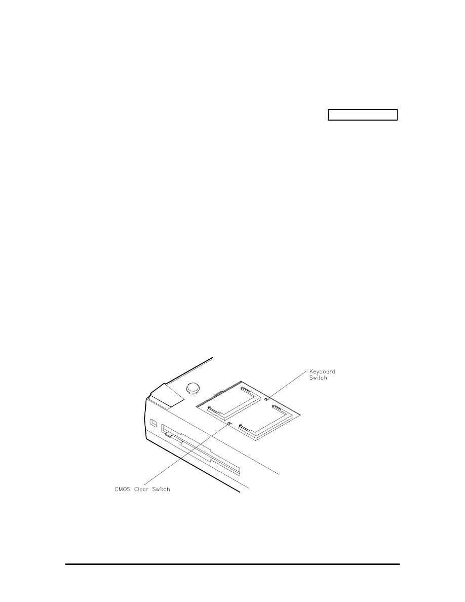
CMOS Clear Switch and Keyboard Switch
The CMOS clear switch is a slide switch located in the memory expansion compartment on
the bottom of the Versa 2000 series system. Use this switch to clear all CMOS settings
including date, time, and system parameters. For example, use the CMOS clear switch if a
user forgets their system password, or during a troubleshooting session. Figure Section 2-3
shows the CMOS switch location.
To clear the CMOS switch, do the following:
1.
Power off the NEC Versa 2000 and remove the expansion memory compartment
cover.
2.
Slide the CMOS Clear switch to On and wait about 30 seconds.
3.
Switch CMOS Clear back to Off.
4.
Replace the expansion memory compartment cover and power on the NEC Versa
2000.
The keyboard switch is also located in the memory expansion compartment on the bottom
of the Versa 2000 series system. Set this switch as follows to select the appropriate
keyboard type:
!"
On
— U.S. Keyboard
!"
Off
— United Kingdom, German Keyboard
Figure Section 2-3 CMOS Clear and Keyboard Switch Locations
SOLD BY laptopia2005 DO NOT RESELL!!
SOLD BY laptopia2005 DO NOT RESELL!!

Smart Power Switch
Provides an automatic feature that prevents you from accidentally powering off the NEC
Versa 2000, and losing your data while your system is in Suspend mode. The smart power
switch senses that the system is in Suspend mode and prevents you from directly powering
off the system when you press the power switch.
To power off the system from Suspend mode,
1.
Press the Suspend/Resume button to make the system active.
2.
Press the power button to turn off the system.
POWER-ON SELF-TEST (POST)
Each time the system is powered on, the system checks the working status of components
through an automatic power-on self-test (POST). The test checks the system configuration
for any discrepancies. One beep means that POST is successful. If any problems in data
transfer or hardware exist, an error message appears.
If the message is an Invalid Configuration message, press
F1 to enter Auto Setup. The
system collects Auto Setup data and lists the changes detected in the current parameter
settings. Press
Enter to review the settings, and make any necessary corrections. For more
complete information, see “Using Auto Setup to Select Parameters.”
If no error messages appear but the system still malfunctions, check the items in the list
below.
!"
The power switch for each peripheral is on.
!"
All cables and power cords are tightly connected.
!"
The electrical outlet is working.
!"
The brightness and contrast controls for the display are adjusted properly.
!"
All options have been properly installed.
NOTE: If the system parameters (date, time,
options, etc.) have not been entered for the
present configuration, enter them when you
complete the setup procedures (see “System
Parameters” in this section).
SOLD BY laptopia2005 DO NOT RESELL!!
SOLD BY laptopia2005 DO NOT RESELL!!
POST Errors
Error messages will appear during POST when configuration information does not match
the settings stored in memory. Error message will also appear if the system loses the
configuration information due to hardware failure.
Refer to Table Section 2-4 for a description of POST error messages.
Table Section 2-4 POST Error Messages
Message Action
Diskette drive n failure
Drive n does not work or is improperly connected (drive n meaning
either drive A or B). Check that drive n is securely connected and
power is on. Press
F1
to start Auto Setup to check the diskette
drive parameters. If a problem still exists, drive n might need
repair.
Diskette read failure - press
F1
to run Auto Setup. Press
any other key to retry boot.
Remove the diskette from drive A and press
F1
to start the system
from the hard disk. Or, insert a bootable disk in drive A and press
F1
.
Non-system disk or disk
error; replace and press any
key when ready.
Remove the diskette from drive A and press any key to start the
system from the hard disk.
No boot device available -
press
F1
to run Auto Setup.
Press
F1
, start Auto Setup and change the hard disk type to the
correct setting. Exit and save Auto Setup.
Invalid configuration
information - run Auto Setup
One or more system configuration parameters are not properly set.
Use Auto Setup to set them correctly. Exit and save to update the
parameters. Connect the AC adapter to charge the battery.
Real-time clock failure
Set time and date using Auto Setup. Exit and save to update the
parameters. Connect the AC adapter to charge the CMOS battery.
Time-of day not set - run
Auto Setup
Set time and date using the Auto Setup. Exit and save to update
the parameters.
Fixed disk failure
Press
F1
to start Auto Setup. Exit and save to update the
parameters. If a problem still exists, check if the drive is installed
properly.
Fixed disk controller failure
Press
F1
. Start Auto Setup. Exit and save to update the
parameters. The hard disk controller is inoperable and requires
repair.
Keyboard clock line failure
The keyboard requires repair.
Keyboard data line failure
The keyboard requires repair.
Keyboard controller failure
The keyboard requires repair.
Keyboard stuck key failure
A key is jammed. Remove any objects interfering with data entry. If
the message remains, the keyboard requires repair.
SOLD BY laptopia2005 DO NOT RESELL!!
SOLD BY laptopia2005 DO NOT RESELL!!

NOTE: If a display related error occurs, it is
indicated by beeps. Display related errors usually
require a system board replacement.
SYSTEM PARAMETERS
The system uses Auto Setup to set and view system parameters. During POST, Auto Setup
detects current system parameters. Read the following subsections for specific uses and
procedures on setting system parameters.
Auto Setup
Auto Setup is a ROM-based program. It is functional when enabled (factory default). Auto
Setup automatically detects current system parameters during the power-on self-test. It also
provides the following functions:
!"
sets date and time
!"
signals any hardware discrepancies during POST via error messages
!"
identifies any parameter(s) changes by blinking double carets (>>)
!"
verifies optional memory installation
!"
integrates security features.
Accessing Auto Setup
Auto Setup is available at power-on:
!"
after POST displays the memory test. Press
F1 when the cursor is a blinking
block.
!"
after the system password is entered (if set)
If there is an error at POST, press
F1 to enter Auto Setup. Check that the hardware settings
match the present configuration.
SOLD BY laptopia2005 DO NOT RESELL!!
SOLD BY laptopia2005 DO NOT RESELL!!

Auto Setup Keys
Refer to Table Section 2-5 for a description of Auto Setup Key functions.
Table Section 2-5 Auto Setup Key Functions
Key Function
Tab
Moves cursor to another field in the menu. For example, pressing
Tab moves the cursor up or down a list of current parameters.
Highlighted letter
Selects menu bar option or parameter with the highlighted letter.
Alt + down arrow
Opens window with a list of parameter settings.
Up or down arrow
Moves cursor up or down a list of parameter settings.
Esc
Exits window without changing parameter settings.
C
Saves parameter changes and closes the window. This function
also opens the Auto Setup Comms menu on the main screen.
Enter
Saves parameter changes and closes the parameter window.
SOLD BY laptopia2005 DO NOT RESELL!!
SOLD BY laptopia2005 DO NOT RESELL!!
AUTO SETUP PARAMETER OPTIONS
Refer to Table Section 2-6 for a complete list of the parameters selectable through Auto
Setup. Parameter descriptions follow the table. Menu selections for Auto Setup are the
same except where noted.
Table Section 2-6 Auto Setup Parameter Options
Menu Default
Setting
Comms
Serial Port
3F8h — 3FF/h/IRQ4 (COM1)
COM Port Plug and Play Option
Reconfigurable
Parallel Port
378 h — 37Fh/IRQ7 (LPT1)
LPT Port Plug and Play Option
Reconfigurable
Parallel Port Mode
Enhanced
Modem Port
2F8h — 2FFh/IRQ3 (COM2 enable)
Internal Modem Port Plug and Play Option
Reconfigurable
Drives
Diskette Drive A
1.44 MB - 3 1/2-inch
Hard Disk Drive 1
Auto Defined Drive Type
Diskette Boot
Enable
Keyboard
Typematic Rate
Normal
NumLock Boot Status
NumLock Off
System Password
Disable
Keyboard Lock HotKey
Disable
Power
Power Management
Longest Battery Life
Power Management under AC
Disable
BackLight
Full
HighLight
Full
Resume on Modem Ring
Disable
Resume on Time of Day
Disable
System
Plug and Play Operating System
Not Present
Quick Boot
Disable
SOLD BY laptopia2005 DO NOT RESELL!!
SOLD BY laptopia2005 DO NOT RESELL!!

Table Section 2-6 Auto Setup Parameter Options
Menu Default
Setting
Time/Date
Time
HR:MIN:SEC
Date
MO/DAY/YEAR
Parameter Descriptions
Read the following for an understanding of each parameter's function.
Comms
This menu item changes the I/O address for the serial, parallel, and intrenal modem ports.
Change the default address and interrupt level only if a conflict exists. The Comms menu
also sets the parallel port mode, and allows configuration for Plug and Play.
For system security, disable a port entirely by selecting the “Disable” setting.
Drives
Sets the diskette drive and/or hard disk drive parameters, plus system security features.
These parameters should be changed when a docking station is connected to the system or
when the hard disk drive is replaced.
Specific drive menu options include the following:
!"
IDE Hard Disk Interface
Disables the built-in IDE controller, making the
Docking Station II's IDE controller the primary controller if the system is docked.
!"
Diskette Boot
Allows user to disable booting from diskette drive, or enable
booting from the diskette drive.
Keyboard
This menu controls keyboard and password options. These options include:
!"
Typematic Rate
Sets the key repeat speed.
!"
NumLock Boot Status
Controls NumLock boot status at power-on.
!"
System Password
Sets the system password. The system boots only after the
system password is entered.
Once the system password is set, the keyboard hotlock key can be enabled.
!"
Keyboard Lock HotKey
Sets Keyboard Lock HotKey security option.
SOLD BY laptopia2005 DO NOT RESELL!!
SOLD BY laptopia2005 DO NOT RESELL!!

Power
Selects the power management features. Remember that these features are inoperative
when the system is connected to the optional Docking Station.
Set the power management level to “Longest Battery Life” for maximum power savings,
“Maximum Performance” for minimal savings, “Personal Setup” for customized power
management, or “Off” to turn off all power management timers.
It is possible to customize the amount of time before local devices shut down to conserve
power by setting these timeout values:
!"
Automatic Suspend
!"
Hard Disk Timer
!"
LCD Panel Timer.
The following power management options are available:
!"
Power Management Under AC
Normally, whenever AC power is connected to
the Versa 2000, power management is disabled. Enabling this option allows the
system to use the power management mode (high, custom, low, or off) that is set
using the Power Management option.
!"
Power Management
Sets power management settings under battery power.
!"
System Suspend Mode
Suspend/Resume stores all necessary system
information in RAM, shuts down all local devices, and stops the processor clock.
!"
BackLight
Sets the LCD backlight to standard or full.
!"
HighLight
Sets the character brightness to standard or full.
!"
Resume on Modem Ring
System automatically powers on when data is
received via a modem.
!"
Resume on Time of Day
Enables the user to specify a time of day to
automatically power on.
System
Use this menu to add to the system's overall performance.
!"
Plug and Play operating system
!"
Quick Boot
Reduces boot time by deleting unnecessary power-on self-tests.
SOLD BY laptopia2005 DO NOT RESELL!!
SOLD BY laptopia2005 DO NOT RESELL!!

Time/Date
Sets the current time and date in military format. To set the time, enter the hour, minute,
and seconds in hh:mm:ss, 24-hour format. For example, type
14:30:00 for 2:30 p.m. Enter
the current day, month, and year for example, mm/dd/yyyy. For example, to enter October
7, 1994, type
10/07/1994.
Remember to type any preceding zeroes. For example, to enter 7:20 a.m., type
07:20:00.
USING AUTO SETUP TO SELECT PARAMETERS
Use the steps below to review or change system parameters.
1.
When no error messages exist, choose a parameter option from the menu bar by
pressing the appropriate highlighted character in the menu.
To select “Comms” press
C. A window shows a parameter menu and the
parameter's current setting. Go to step 3.
If an error message occurred during POST, use Auto Setup as follows:
!"
Note the blinking double carets (>>) that mark the changed parameter(s).
!"
Either accept the change(s) by pressing
Enter and return to the Auto Setup
Summary screen, or
!"
Change the parameter to the correct setting using the steps that follow.
2.
Press
Tab or the arrow keys to place the cursor on the parameter.
3.
Press the
Alt
↓↓↓↓
to view the parameter settings. A list of parameter choices
appears.
To select a setting, press
↓↓↓↓
to position the cursor on the appropriate setting. Press
Enter. Auto Setup processes the change, exits the window and returns to the
parameter menu.
Press
Esc to return to the summary screen without saving changes.
4.
Press
X to exit the menu bar.
5.
Use
↓↓↓↓
to select “Exit and Save Changes” and press
Enter.
6.
Press
Enter again. The system reboots with the latest changes.
SOLD BY laptopia2005 DO NOT RESELL!!
SOLD BY laptopia2005 DO NOT RESELL!!

SECURITY OPTIONS
The system supports two types of passwords for system security:
!"
system password
!"
keyboard lock hotkey.
The following contains instructions for setting and using the password feature.
System Password
Use the system password to lock the system at power-on. The system password is set using
Auto Setup. This locks the keyboard to prevent unauthorized access to the system. When a
system password is set, the password must be entered before entering Auto Setup. This
feature allows only authorized access to system parameters.
Set an initial password as follows.
1.
Select the Keyboard menu option in Auto Setup.
2.
Select “System Password” on the Keyboard parameter menu in Auto Setup.
3.
Select “Enter and Enable”.
4.
At the prompt, enter up to seven characters in length and press
Enter. Another
window appears with a prompt to re-enter the password for verification.
5.
Re-enter the password and press
Enter. Auto Setup returns to the Keyboard
parameter menu.
6.
Save the changes and return to the initial summary screen.
7.
Exit Auto Setup and save the changes.
NOTE: Once a system password is entered, it
cannot be edited or disabled in Auto Setup. See
procedures for removing or replacing a password
later in this section.
Using the System Password
After setting the initial password, a password prompt appears each time the system is
powered on. The password prompt is a key icon. The key icon appears after the completion
of POST.
To use the password, boot the system by powering the system off and then on. At the
password prompt (key icon), enter the password and press
Enter to load the operating
system or to enter Auto Setup.
SOLD BY laptopia2005 DO NOT RESELL!!
SOLD BY laptopia2005 DO NOT RESELL!!

NOTE: The characters entered do not appear on
the screen.
If it takes more than three tries to enter the correct password, power off the system and try
again.
Remove a password or replace a current password with a new one as follows.
!"
To remove a password, type at the password prompt the current password and a
forward slash in the following format:
current password/
Press
Enter. The password clears and the prompt no longer appears at power-on.
!"
To replace the current password with a new one, at the password prompt type the
current password, a slash, and the new password in the following format:
current password/new password
Press
Enter. The password changes to the new password. Enter the new
password at the next power-on.
Keyboard Lock Hotkey
The system supports a keyboard lock feature for additional security. The lock option
appears on the Auto Setup screen only after you have enabled a password. At this point in
Auto Setup, the lock can be enabled or disabled.
To lock the keyboard, press
Ctrl + Alt + Back Space
. To unlock the keyboard, enter the
password. If the password is removed, this option is no longer available.
SOLD BY laptopia2005 DO NOT RESELL!!
SOLD BY laptopia2005 DO NOT RESELL!!

NEC UTILITIES
To view the list of NEC utilities and drivers, go to the cardwiz directory. To get into the
cardwiz directory, type
cardwiz. Press Enter.
NOTE: Most applications, such as
communications software, are not PCMCIA
aware. Make sure the card is inserted and ready
before using an application.
BIOS Update Utility (BUU)
The BIOS Update utility updates the ROM BIOS version of the system. This software
utility updates the Flash ROM installed on the system board. The utility identifies and
saves the currently installed BIOS version before installing the new version.
To receive the latest BUU diskette (in the U.S. only), call the Technical Support Center at
(800) 388-8888 or download the BUU by logging onto NEC's Electronic Bulletin Board
System (BBS) and perform the procedures described in the following subsections.
To use the BIOS Update utility, the system configuration must be set to 640 KB of base
memory with the programming voltage enabled.
Precautions
The BIOS Update utility diskette saves the old BIOS version. Make sure the diskette is not
write-protected. If attempting to use a diskette that has updated another unit, a message
warns that the original BIOS may not be restored. If updating more than one system, first
make a copy of the original diskette for each system before using the diskette.
SOLD BY laptopia2005 DO NOT RESELL!!
SOLD BY laptopia2005 DO NOT RESELL!!

Downloading the Update Utility
To receive the latest version of the BIOS Update utility, perform the following steps.
1.
Log onto NEC's BBS by dialing (508)-635-4706. The BBS parameters are as
follows.
!"
Baud rate:
300 to 14,400 Kbps
!"
Parity:
none
!"
Data bits:
8
!"
Stop bits:
1
2.
Once connected, a name and password must be entered. When connecting for the
first time, a questionnaire must be completed.
3.
At the NEC/Technologies Bulletin Board main menu, type
F and then press
Enter for the File Menu.
4.
At the File Menu, type
D and then press Enter for download.
5.
Type the file name,
L440nB3.EXE, and press Enter. Insert the correct revision
number in place of the n.
6.
Press
Enter again.
7.
Set the default protocol on the BBS.
8.
The BBS displays a prompt that it is ready to send the file. Perform the software's
download transfer procedure. The files are sent to the hard drive. Execute the file
to create a bootable disk. A message prompts you to insert a 1.44-MB diskette
drive in drive A. Make sure that it is a high-density diskette. Press any key to
continue.
After pressing any key, the diskette is formatted and the BIOS update files are
copied to the diskette.
9.
After the download is completed, log off the BBS.
NOTE: If you don’t know the filename, join the
laptop conference to find the BIOS or driver disk
you need.
Using the Update Utility
Load the BIOS Update utility as follows.
SOLD BY laptopia2005 DO NOT RESELL!!
SOLD BY laptopia2005 DO NOT RESELL!!

CAUTION: Never load a BUU from another
system model. That system's BIOS will be lost.
1.
Power off the system unit.
2.
Insert the BIOS Update Utility diskette into drive A.
3.
Power on the system unit. The unit boots and automatically loads the utility. A
message similar to the following appears:
FLASH ROM EQUIPPED
WARNING: The BIOS Update Procedure
is about to begin, press ENTER to continue.
To abort, remove the diskette and reset the unit.
5.
Press
Enter to continue. The utility checks the currently installed BIOS version
and the diskette's BIOS versions. If the BIOS can be updated, the Main Menu
appears (see the following screen). If there is a problem, the appropriate message
is displayed.
NEC BIOS Update Utility
Main Menu
Information
Display BIOS Version
Customize BIOS
Install New BIOS
Restore Original BIOS
Exit
SOLD BY laptopia2005 DO NOT RESELL!!
SOLD BY laptopia2005 DO NOT RESELL!!

Menu Functions
Use the Main Menu to update the BIOS version; other menu functions are optional. To
select a menu function, use the arrow keys to highlight the function and press
Enter. If
help is needed, press
F1 for additional information.
Information
This option provides important information about the BIOS Update utility. Read this
information before proceeding with the utility.
Display BIOS Version
Use this option to display the currently installed BIOS version and the version of the new
replacement BIOS. A message similar to the following appears.
NOTE: The original BIOS version level is
included if the utility was run previously.
The currently installed BIOS version:
xx.xx.xx
The new BIOS version:
xx.xx.xx
The original BIOS version:
xx.xx.xx
Press any key to continue. . .
SOLD BY laptopia2005 DO NOT RESELL!!
SOLD BY laptopia2005 DO NOT RESELL!!

Customize BIOS
Use this option to customize the BIOS when the new BIOS is installed. When selected, a
message similar to the following appears.
The edit option creates or changes a custom sign-on message. This sign-on message can be
up to 40 characters and is displayed every time the system boots. View shows the sign-on
message, if any, that will be installed into the new BIOS. The clear function erases the
custom sign-on message. Exit returns to the Main Menu.
Install New BIOS
This menu option first saves the system's original BIOS to the diskette and then installs the
new BIOS. Be sure to choose the Customize BIOS feature, if desired, before selecting this
option. This procedure may require 10 to 60 seconds. A continuous sound pattern means a
failure.
Edit Sign-on Messages
View Sign-on Message
Clear Sign-on message
Return
SOLD BY laptopia2005 DO NOT RESELL!!
SOLD BY laptopia2005 DO NOT RESELL!!

When selecting the Install New BIOS function, a message similar to the following appears.
The utility updates the BIOS and resets the system to make the new version operational. To
reuse the utility, power the system off and back on again with the BIOS Update Utility
diskette inserted in drive A.
Restore Original BIOS
Use this option to restore the previous BIOS from the update diskette. If the system BIOS
was not updated, this function does nothing. A message indicates the new BIOS must be
installed before the original BIOS can be restored.
This procedure will install the new BIOS
in your system.
After the new BIOS is installed, your system
will be reset.
Enter “Y” to continue [N]
Note: Your current BIOS will be saved if a
copy of it does not already exist on this disk.
Warning: Do NOT disturb the system while
update procedure is in progress.
SOLD BY laptopia2005 DO NOT RESELL!!
SOLD BY laptopia2005 DO NOT RESELL!!

This procedure installs the previously saved BIOS in the system. Selecting this function
displays a message similar to the following.
This procedure may require 10 to 60 seconds. A continuous sound pattern means a failure.
The utility restores the previous BIOS and resets the system to make the previous version
operational. To reuse the utility, power the system off and back on again with the BIOS
Update Utility diskette inserted in drive A.
Exit
This option exits the utility and resets the system. Press
Esc to return to the Main Menu.
Press
Enter to exit the utility.
This procedure installs the previously
saved BIOS in your computer.
After the new BIOS is restored, your
system is reset.
Enter “Y” to continue [N]
Warning: Do NOT disturb the system
while the restore procedure is in
progress.
SOLD BY laptopia2005 DO NOT RESELL!!
SOLD BY laptopia2005 DO NOT RESELL!!

POWER SOURCES
For optimum performance and power conservation, use the AC adapter to power the Versa
2000 series system. Other power sources include the battery pack, the optional car DC
adapter and the optional docking station .
AC Adapter
The AC adapter allows the system to operate with AC power, recharges the battery pack,
and maintains the bridge battery. The internal backup battery allows the system to retain
system parameter information.
NOTE: Make sure that the AC adapter is
connected at all times. It will continue to charge
the battery pack and bridge battery during
operation or when the system is turned off.
If the AC adapter is used primarily, remove the battery pack to reduce system weight.
CAUTION: Only use the AC adapter model
provided with the Versa 2000 series system.
SOLD BY laptopia2005 DO NOT RESELL!!
SOLD BY laptopia2005 DO NOT RESELL!!
Connect the AC adapter as follows:
1.
Connect the adapter's DC cable to the power connector on the rear of the system.
Connect the other end to the AC adapter.
Figure Section 2-4 Connecting the AC Adapter
2.
Connect one end of the AC power cable to the AC adapter. Connect the other end
of the AC power cable to a 100- to 240-volt, AC wall outlet.
Battery Power
It is highly recommended to use battery power only when an AC outlet is unavailable. A
fully charged battery pack lasts approximately 5.5 hours under maximum power save
mode, and 2.5 hours without power save mode.
The actual amount of battery time depends on the use of power-saving features, the
application, options installed, and the environment.
Refer to the Battery Status table in the LEDs section for information on determining how
much battery power is currently available.
SOLD BY laptopia2005 DO NOT RESELL!!
SOLD BY laptopia2005 DO NOT RESELL!!
Recharging the Battery Pack
There are two ways to recharge the battery pack, Quick Charge and Normal Charge.
A Quick Charge is performed when the system is off or in Suspend mode with the AC
adapter connected. A Normal Charge is performed when the AC adapter is connected and
the system is on. When the battery status LED shows an orange light or blinking orange
light, it is time to recharge the battery. .
To recharge the battery, simply attach the AC adapter to the system. Charging the battery
pack with a Quick Charge takes 1.6 hours with power off. Charging the battery pack with a
Normal Charge takes 6 to 9 hours with power on. These time increments assume that there
are no options connected to the Versa 2000.
REPLACING THE BATTERY PACK
To replace the battery pack with a fully charged battery, press the suspend button to
activate Suspend mode. It is not necessary to turn off system power as long as Suspend
mode is activated. The bridge battery maintains data and system status for up to 5 minutes
while in Suspend mode. Use the steps below to install a charged battery pack.
1.
If power is on, push the suspend switch to put the system in Suspend mode. The
bridge battery saves the memory contents and system status.
2.
Remove the battery cover.
3.
Locate the battery release latch on the bottom of the system. Push the release
latch while removing the battery pack from the compartment.
Figure Section 2-5
Battery Release Latch Location
SOLD BY laptopia2005 DO NOT RESELL!!
SOLD BY laptopia2005 DO NOT RESELL!!
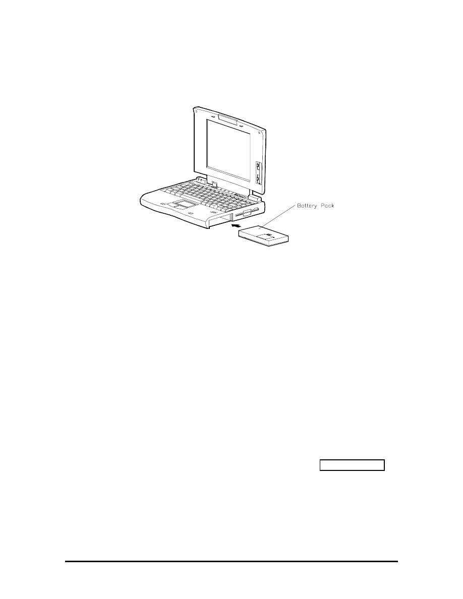
4.
Insert the new battery pack into the battery compartment. Push the battery pack
into the compartment until it locks into place.
Figure Section 2-6
Battery Pack Replacement
3.
Replace the battery cover.
4.
Exit Suspend mode.
Saving Battery Power
The system utilizes two power conserving states: Active and Suspend mode. The system
automatically switches between these modes to conserve battery power and prolong battery
life. To save additional power, use the following guidelines:
!"
put the system in Suspend mode when you need to leave the system for a short
time
!"
reduce the LCD's brightness using the Fn F5 hot key to toggle the LCD backlight
between standard or full
!"
turn off the system when not in use.
The system also integrates automatic power-saving features. Refer to Table Section 2-7 for
a complete description.
SOLD BY laptopia2005 DO NOT RESELL!!
SOLD BY laptopia2005 DO NOT RESELL!!

AUTOMATIC POWER-SAVING FEATURES
Table Section 2-7 lists the Versa 2000 series automatic power conserving features. These
features work during battery and AC operation. The features listed below do not work
when the optional docking station is connected. Battery life is also maintained by using the
power management levels listed in the next section.
The default timeouts listed below can be changed using Auto Setup. The NEC Power
Center Utility icon also allows you to change the timeout period for some of these devices.
Use the
Fn F7 key combination to set the power management level. You can toggle
between Highest Performance, Longest Battery Life, Custom Values, and Off. You can
modify the custom level for your specific working environment using Custom Values.
Default values change depending on the type of power management you use.
Table Section 2-7
Automatic Power-Saving Features
Device Default
(timeout)
Description
LCD backlight
2 min.
When no keyboard or NEC VersaGlide input
occurs for the specified timeout, the LCD
backlight shuts off.
Hard Disk
1 min.
Hard disk motor stops when not accessed for
specified timeout.
Suspend Mode
10 min.
The system enters Suspend mode after total
system activity.
Power Saving Levels
The power saving levels work transparent to system applications and can be set by the user
through Auto Setup. See “System Parameters” earlier in this section for information on
using Auto Setup to select power management levels. The two levels for conserving battery
power are as follows.
Active Mode
The system uses full power. All components are turned on and active.
Suspend Mode
Suspend mode conserves power by shutting off all system components while storing RAM contents and
system status. The system returns to Active mode when the suspend button is pressed or if an optional modem
receives data.
SOLD BY laptopia2005 DO NOT RESELL!!
SOLD BY laptopia2005 DO NOT RESELL!!
Section 3
Illustrated Parts Breakdown
This subsection contains the illustrated parts breakdown (IPB) and NEC part numbers for
the Versa 2000 series system. Error! Reference source not found. shows the field-
replaceable parts for the system.
Table Section 3-8 lists option, documentation, and shipping carton part numbers.
NOTE: In the U.S., call 1(800) 388-8888 to
order NEC spare parts. To order options in the
U.S., call your local sales office.
Table Section 3-8 Versa 2000 Series Field-Replaceable Parts*
Item Description
Part
Number
1
Modem Cover
136-238077-001A
2
Modem Port Cover (small plastic)
136-619064-001A
3
Modem Board
808-874740-001A
4
PCMCIA Cover
136-238068-001A
5
Foot (left)
136-619045-001A
6
AC Power Cable
808-740591-001A
7
AC Adapter
808-891828-002A
8a
Versa 2000 Logo (DSTN)
158-030780-000
8b
Versa 2000 Logo (TFT)
158-030780-001
9a
Front Cover Assembly (bezel, DSTN)
136-619073-001A
9b
Front Cover Assembly (bezel, TFT)
136-619074-001A
10a
LCD Sub-assembly (DSTN)
136-238073-001A
10b
LCD Sub-assembly (TFT)
136-238074-001A
11
LCD Lock Shaft
136-619099-A
12
LCD Lock Spring
136-619083-A
13 LCD
Lock
136-619082-001A
14
Screw Covers (rubber)
136-619087-A
15a
Top Case Assembly (TFT)
136-238070-002A
*
This data was prepared July 1995. For an up-to-date listing of spare parts, please call FastFacts
(800) 366-0476 and order document number 42181268
SOLD BY laptopia2005 DO NOT RESELL!!
SOLD BY laptopia2005 DO NOT RESELL!!

Table Section 3-8 Versa 2000 Series Field-Replaceable Parts*
Item Description
Part
Number
15b
Top Case Assembly (DSTN)
136-238070-001A
16a Keyboard
(Domestic)
808-897250-004A
16b Keyboard
(German)
808-897250-003A
16c
Keyboard (United Kingdom)
808-897250-002A
17 Glidepoint
Assembly
808-874649-003A
18 Speaker
Assembly
808-874738-001A
19 Bridge
Battery
804-021231-001A
20 Battery/Speaker
Holder
136-619095-001A
21
Metal Keyboard Support
136-238071-A
22
CMOS Battery (Lithium)
808-874741-001A
23a
Main Board Assembly, 75 MHz/4 MB (DSTN)
136-238075-003A
23b
Main Board Assembly, 75 MHz/4 MB (TFT)
136-238075-004A
23c
Main Board Assembly, 75 MHz/8 MB(TFT)
136-238075-002A
24
1.44-MB Diskette Drive
808-874617-001A
25 Foot
(right)
136-619046-001A
26
Serial/Parallel Connector Cover
136-238065-001A
27
Dock/Video Connector Cover
136-238066-001A
28 FDD
Cable
808-874731-001A
29 Battery
Cover
136-619059-001A
30 Main
Battery
804-021230-001A
31
Bottom Case Assembly
136-238062-001A
32
Memory Cover (RAM)
136-238063-001A
33 Rubber
Foot
808-814221-043A
34a
350-MB Hard Disk Drive
136-237726-001A
34b
540-MB Hard Disk Drive
136-237726-002A
34c
720-MB Hard Disk Drive
136-237726-003A
35
Hard Disk Drive Cover
136-238067-001A
36 GlidePoint
Cable
808-874732-001A
37
Intel Inside Sticker
808-095733-001A
38 LED
Cable
808-874735-001A
39a
LCD Cable (DSTN)
808-874733-001A
39b
LCD Cable (TFT)
808-874734-001A
SOLD BY laptopia2005 DO NOT RESELL!!
SOLD BY laptopia2005 DO NOT RESELL!!

Table Section 3-8 Versa 2000 Series Field-Replaceable Parts*
Item Description
Part
Number
40 Modem
Cable
158-050519-005
41
NEC Logo Badge
136-600325-A
42*
Plastic Carrying Case
158-040505-000
43*
4-MB Memory Card
136-266472-A
44*
8-MB Memory Card
158-082642-070
* Not shown in IPB figure
SOLD BY laptopia2005 DO NOT RESELL!!
SOLD BY laptopia2005 DO NOT RESELL!!

SOLD BY laptopia2005 DO NOT RESELL!!
SOLD BY laptopia2005 DO NOT RESELL!!

Table Section 3-9 Option and Documentation Part Numbers *
Description Model
Number
540-MB Hard Disk Drive
OP-220-60001
720-MB Hard Disk Drive
OP-220-60002
AC Adapter
OP-520-60001
NEC Versa 2000 Series MiniDock
OP-560-60001
Li-ION Battery Pack
OP-570-60001
2400/9600bps Data/Fax Modem
OP-710-4008
14.4Kbps Data/Fax Modem (PCMCIA)
OP-710-4009
5-MB Storage Card
OP-730-4202
NEC VersaPage PC-Card Pager
OP-710-4411
High Performance Ethernet Card
OP-720-1201
NEC VersaVideo Portable Digital Video Card OP-750-4701-1
500 Kbps SCSI Card
OP-740-4001
NEC Versa 2000 Series Quick Setup Sheet
819-181280-000
NEC Versa 2000 Series User's Guide
819-181279-000
NEC Versa 2000 Series Service and
Reference Guide
819-181268-000
Internal 14.4 Kbps Modem
OP-440-60001
PS/2 Y Adapter
OP-510-1201
Battery Charger
OP-570-60002
*
This data was prepared July 1995. For an up-to-date listing of spare parts, please call FastFacts
(800) 366-0476 and order document number 42181268
SOLD BY laptopia2005 DO NOT RESELL!!
SOLD BY laptopia2005 DO NOT RESELL!!
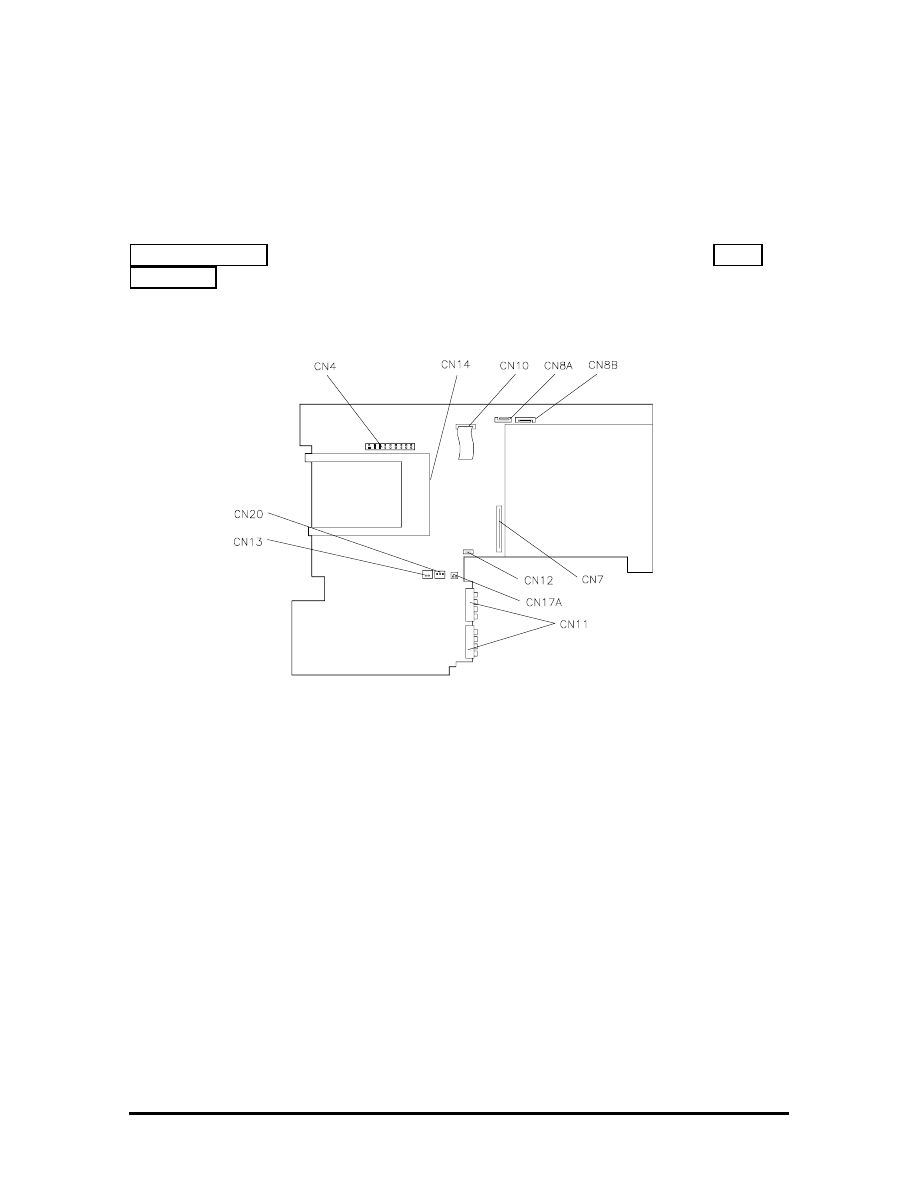
Section 4Appendix A
Connector Locations and Pin
Assignments
Figure Section 4-1 shows the connectors on the Versa 2000 series system board. Table
Section 4-1 lists connector descriptions. The remaining tables provide pin assignments for
system connectors.
Figure Section 4-1 System Board Connector Locations
SOLD BY laptopia2005 DO NOT RESELL!!
SOLD BY laptopia2005 DO NOT RESELL!!

Table Section 4-1 System Board Connectors
Connector Description
CN13
Bridge Battery
CN20 Speaker
Connector
CN4 LCD
Connector
CN14 PCMCIA
Connector
CN10 LED
Connector
CN8A and CN8B
Keyboard Connectors
CN7
Diskette Drive Connector
CN12 VersaGlide
Connector
CN17A
Lithium Battery Connector
CN11
Battery Pack Connector
Table Section 4-2 Keyboard/Mouse Connector Pin
Assignments
Pin Signal
1 KeyboardData
2 MouseData
3 Ground
4 +5V
5 Keyboard
Clock
6 Mouse
Clock
SOLD BY laptopia2005 DO NOT RESELL!!
SOLD BY laptopia2005 DO NOT RESELL!!
Table Section 4-3 Serial Port Connector Pin Assignments
Pin Signal
1 Data
Carrier
2 Receive
Data
3 Transmit
Data
4
Data Terminal Ready
5 Ground
6
Data Set Ready
7
Request to Send
8
Clear to Send
9 Ring
Indicator
Table Section 4-4 CRT Connector Pin Assignments
Pin Signal
1
Red
2
Green
3
Blue
4
No Connection
5
Ground
6
Ground
7
Ground
8
Ground
9
+5V PnP VESA Vcc
10 Ground
11 No
Connection
12
PnP VESA Data
13 Horizontal
Sync
14 Vertical
Sync
15
PnP VESA Clock
SOLD BY laptopia2005 DO NOT RESELL!!
SOLD BY laptopia2005 DO NOT RESELL!!

Table Section 4-5 Parallel Printer Pin Assignments
Pin Signal
1
- Strobe
2
Data Bit 0
3
Data Bit 1
4
Data Bit 2
5
Data Bit 3
6
Data Bit 4
7
Data Bit 5
8
Data Bit 6
9
Data Bit 7
10 -
Acknowledge
11 Busy
12 PE
13 Select
14
- Auto Feed XT
15 -
Error
16 -
Initialize
17
- Select In
18 -25
Ground
SOLD BY laptopia2005 DO NOT RESELL!!
SOLD BY laptopia2005 DO NOT RESELL!!

Table Section 4-6 Docking Connector Pin Assignments
Pin Signal
1
+5V
2
+5V
3
DSDET2
4-23
Ground
24
DSDET2
25-32
+12V CHG
33
Docking Station Detect
34
AGND
35
AGND
36
AGND
37
TC
38
BALE
39
IOCHCK
40
IOCHRDY
41
AEN
42
SBHE
43
MEMR
44
MEMW
45
RESET DRV
46
OWS
47
SMEMR
48
SMEMR
49
IOR
50
IOW
51
IOCS16
52
PC Detect
53
HDD Access
54
FDD Access
55
Mouse Clock
56
Mouse Data
57
Keyboard Clock
SOLD BY laptopia2005 DO NOT RESELL!!
SOLD BY laptopia2005 DO NOT RESELL!!

Table Section 4-6 Docking Connector Pin Assignments
Pin Signal
58
Keyboard Data
59
Reserved
60
+12V Sys
61
Floppy Track 0
62
Through
66
+12V Sys
67
CRT Red
68
CRT Green
69
SA17
70
SA18
71
SA19
72
MENCS16
73
Refresh
74
Printer-Strobe
75
Printer-Acknowlg
76
Printer-Busy
77
Printer-P End
78
Printer Select
79
Printer-Auto FD
80
Printer -Error
81
Printer-Initialize
82
Printer Select In
83
FD Head Select
84
FD-Direction In
85
FD-Boot Select
86
FD-Low Density
87
FD-Write Enable
88
FD-Step
89
LA23
90
LA22
91
LA21
SOLD BY laptopia2005 DO NOT RESELL!!
SOLD BY laptopia2005 DO NOT RESELL!!

Table Section 4-6 Docking Connector Pin Assignments
Pin Signal
92
LA20
93
LA19
94
LA18
95
LA17
96
FD-Write Protect
97
FD-Disk Change
98
FD-Read Data
99
FD-Index
100 CRT-Blue
101 CRT-HSync
102 SD8
103 SD9
104 SD10
105 SD11
106 SD12
107 SD13
108 SD14
109 SD15
110 Master
111 Serial-CD
112 Serial-TXD
113 Serial-RXD
114 Serial-DTR
115 Serial-DSR
116 Serial-RTS
117 Serial-CTS
118 Serial-RI
119 FD-Drive
Select
120 FD-Motor
0
121 SD7
122 SD6
123 SD5
SOLD BY laptopia2005 DO NOT RESELL!!
SOLD BY laptopia2005 DO NOT RESELL!!

Table Section 4-6 Docking Connector Pin Assignments
Pin Signal
124 SD4
125 SD3
126 SD2
127 SD1
128 SD0
129-132 Reserved
133 CRT-VSync
134 CLK1
135 PR-D2
136 PR-D4
137 PR-D6
138 IRQ3
139 IRQ5
140 IRQ7
141 IRQ10
142 IRQ12
143 IRQ15
144 DRQ1
145 DRQ3
146 DRQ6
147 DACK0
148 DACK2
149 DACK5
150 DACK7
151
FD-Drive Select 1
152 FD-Motor
1
153 FD-Write
Data
154 SA15
155 SA13
156 SA11
157 SA9
158 SA7
SOLD BY laptopia2005 DO NOT RESELL!!
SOLD BY laptopia2005 DO NOT RESELL!!
Table Section 4-6 Docking Connector Pin Assignments
Pin Signal
159 SA5
160 SA3
161 SA1
162
Audio Analog Ground
163
Audio Analog Ground
164 Line-in
Right
165 Line-in
Left
166 PR-D0
167 PR-D1
168 PR-D3
169 PR-D5
170 PR-D7
171 IRQ4
172 IRQ6
173 IRQ9
174 IRQ11
175 IRQ14
Table Section 4-7 Power Connector
Pin Signal
1 Not
Defined
2 +19V
3 Ground
SOLD BY laptopia2005 DO NOT RESELL!!
SOLD BY laptopia2005 DO NOT RESELL!!

Table Section 4-8 Hard Disk Drive Connector
Pin Signal
1
HDD Access LED
2
+5V
3
Chip Select 0
4
+5
5
Chip Select 1
6
+5V
7
Address 0
8
+5V
9
Addrss 2
10 +5V
11 Address
1
12 +5V
13 Diagnostic
14 Not
Used
15 IRQ
16 Not
Used
17 IO16I
18
IO Channel Ready
19 Cable
Select
20 IO
Write
21 I/O
Read
22 Not
Used
23 Data
0
24 Data
1
25 Data
15
SOLD BY laptopia2005 DO NOT RESELL!!
SOLD BY laptopia2005 DO NOT RESELL!!

Table Section 4-9 Diskette Drive Connector
Pin Signal
1
SIDE
2
FDCNT
3
RDATA
4
No Connection
5
WPRT
6
Ground
7
Ground
8
No Connection
9
TRK0
10 Ground
11 WE
12 No
Connection
13 WDATA
14 Ground
15 Ground
16 No
Connection
17 STEP
18 Ground
19 DIR
20 No
Connection
21 No
Connection
22 MOTOR
23 DSKCHG
24 No
Connection
25 DRVSEL
26 VCC
27 VCC
28 No
Connection
29 INDEX
30 VCC
SOLD BY laptopia2005 DO NOT RESELL!!
SOLD BY laptopia2005 DO NOT RESELL!!

Section 5Index
A
AC adapter, 2-24
Accessing auto setup, 2-9
Active mode, 1-17, 2-28
APM, 2-17
Auto setup, 2-9
Auto setup keys, 2-10
Auto setup options, 2-11
Automatic power saving, 2-28
B
Backlight, 2-13
Battery charging time, 2-26
Battery Pack, 1-4
Battery power, 2-25
BIOS update, 1-13
Bridge battery, 1-4, 2-24
BUU menu functions, 2-20
BUU precautions, 2-17
C
Cable connections, 2-2
CardSoft, 2-17
CardView, 2-17
Chip types, 1-11
CMOS battery, 1-4
CMOS switch, 2-6
Connecting the AC adapter, 2-25
Controls and switches, 2-3
CRT connector pin assignments, A-3
CRT port, 1-3
D
Diskette boot, 2-12
Diskette connector assignments, A-11
Diskette controller, serial interface, parallel interface, 1-14
Downloading the BUU, 2-18
DSTN, 1-3
E
Expansion port pin assignments, A-9
SOLD BY laptopia2005 DO NOT RESELL!!
SOLD BY laptopia2005 DO NOT RESELL!!

External keyboard connector pin assignments, A-2
F
Flash ROM, 1-12, 2-17
Function keys, 2-5
H
Hard disk drive connector pin assignments, A-10
Hardware failures, 2-8
Hardware overview, 1-2
Highlight, 2-13
I
I/O connector descriptions, 2-2
Increasing system memory, 1-5
Interrupt level assignments, 1-16
K
Keyboard, 1-4
Keyboard controller, 1-14
Keyboard lock hot key, 2-16
Keyboard lock hot keys, 2-12
Keyboard select switch, 2-4
Keyboard switch, 2-6
L
LCD
LCD types, 1-3
LCD backlighting, 1-3
LED descriptions, 2-4
Local device timers, 1-18
Local power management, 1-17
M
Memory map, 1-6
Microprocessor, 1-1
N
NEC utilities, 2-17
Normal charge, 2-26
O
Operating controls, 2-3
Option part numbers, 3-4
SOLD BY laptopia2005 DO NOT RESELL!!
SOLD BY laptopia2005 DO NOT RESELL!!

P
Parallel interface enhanced capabilities port, 1-11
Parallel port pin assignments, A-4
Parameter descriptions, 2-12
comms, 2-12
drives, 2-12
keyboard, 2-12
power, 2-12
PCMCIA controller, 1-14
PCMCIA drivers/utilities, 1-14
PCMCIA Slots, 1-4
Pentium, 1-1
Peripheral controller, 1-13
Plug and play, 1-18
PnPVFD, 2-17
Post error messages, 2-8
Post errors, 2-8
Power connector pin assignments, A-9
Power management modes
active, 1-17
local standby, 1-17
suspend, 1-17
Power management overview, 1-17
Power management switch, 2-4
Power management under AC, 2-13
Power saving levels, 2-28
Power sources, 2-24
Power switch, 2-4
Power-on self test (POST), 2-7
Q
Quick boot, 2-13
Quick charge, 2-26
R
Rear panel connectors, 1-2
Recharging the battery pack, 2-26
Remove a password, 2-16
Replacing the battery pack, 2-26
Reset switch, 2-4
Resume on modem ring, 2-13
Resume on time of day, 2-13
ROM BIOS, 1-12
SOLD BY laptopia2005 DO NOT RESELL!!
SOLD BY laptopia2005 DO NOT RESELL!!

S
Saving battery power, 2-27
Security options, 2-15
Serial interface, 1-11
Serial port connector pin assignments, A-3
Shipping configurations, 1-1
Smart power switch, 2-7
Suspend mode, 1-17, 2-26, 2-28
Suspend warning tone, 2-13
System board, 1-3
System board connectors, A-1
System logic, 1-12
System memory, 1-5
System parameters, 2-7, 2-9
System password, 2-12, 2-15
System setup, 2-1
System suspend mode, 2-13
System video, 1-7
T
TFT, 1-3
Time/date, 2-14
Typematic rate, 2-12
U
Unpacking, 2-1
Using auto setup, 2-14
Using the update utility, 2-18
V
Versa 2000 I/O address map, 1-15
Versa 2000 parts list, 3-1
Versa 2000 system specifications, 1-19
VersaGlide, 1-5
VGA controller, 1-13
Video controller architecture, 1-13
Video mode
640x480 DSTN, simultaneous CRT, 1-9
640x480 TFT, simultaneous CRT, 1-9
CRT only, 1-7
Video RAM, 1-7
SOLD BY laptopia2005 DO NOT RESELL!!
SOLD BY laptopia2005 DO NOT RESELL!!
Document Outline
- HARDWARE OVERVIEW
- SYSTEM MEMORY
- SYSTEM VIDEO
- PARALLEL INTERFACE
- SERIAL INTERFACE
- NEC VERSA 2000 SERIES CHIP SET
- POWER MANAGEMENT OVERVIEW
- SPECIFICATIONS
- UNPACKING THE SYSTEM
- SETUP
- OPERATING CONTROLS
- POWER-ON SELF-TEST (POST)
- SYSTEM PARAMETERS
- AUTO SETUP PARAMETER OPTIONS
- USING AUTO SETUP TO SELECT PARAMETERS
- SECURITY OPTIONS
- NEC UTILITIES
- POWER SOURCES
- REPLACING THE BATTERY PACK
- AUTOMATIC POWER-SAVING FEATURES
- Appendix A
- Index
Wyszukiwarka
Podobne podstrony:
więcej podobnych podstron