A n I n t ro d u c t i o n
t o E l e c t ro m a g n e t i s m
By Larry E. Schafer
Featuring sciLINKS
©
óa new way of connecting text and
the Internet. Up-to-the-minute online content, classroom
ideas, and other materials are just a click away.
Go to page xiii to learn more about this educational resource.
Arlington, Virginia

Shirley Watt Ireton, Director
Beth Daniels, Managing Editor
Judy Cusick, Associate Editor
Jessica Green, Assistant Editor
Linda Olliver, Cover Design
Art and Design
Linda Olliver, Director
NSTA Web
Tim Weber, Webmaster
Periodicals Publishing
Shelley Carey, Director
Printing and Production
Catherine Lorrain-Hale, Director
Publications Operations
Erin Miller, Manager
sciLINKS
Tyson Brown, Manager
National Science Teachers Association
Gerald F. Wheeler, Executive Director
David Beacom, Publisher
NSTA Press, NSTA Journals,
and the NSTA website deliver
high-quality resources for
science educators.
Charging Ahead: An Introduction to Electromagnetism
NSTA Stock Number: PB155X
ISBN 0-87355-188-5
Library of Congress Card Number: 2001086220
Printed in the USA by FRY COMMUNICATIONS, INC.
Printed on recycled paper
Copyright © 2001 by the National Science Teachers Association.
The mission of the National Science Teachers Assocation is to promote
excellence and innovation in science teaching and learning for all.
Permission is granted in advance for reproduction for purpose of classroom
or workshop instruction. To request permission for other uses, send
specific requests to:
NSTA Press
1840 Wilson Boulevard
Arlington, Virginia 22201-3000
www.nsta.org

Acknowledgments .......................................................................................................... iv
Overview .......................................................................................................................... v
A Learning Map on Electricity and Magnetism ........................................................ viii
Guide to Relevant National Science Education Content Standards ..................... xii
sciLINKS ........................................................................................................................... xiii
A c t i v i t y l : A B o n u s f ro m E l e c t r i c a l F l o w — M a g n e t i s m
Student Worksheet ........................................................................................................ 1
Teacher’s Guide to Activity 1 ..................................................................................... 9
A c t i v i t y 2 : C o i l s a n d E l e c t ro m a g n e t s
Student Worksheet ........................................................................................................ 13
Teacher’s Guide to Activity 2 ..................................................................................... 21
A c t i v i t y 3 : M a k i n g a n E l e c t r i c M o t o r —
E l e c t ro m a g n e t i s m i n A c t i o n
Student Worksheet ........................................................................................................ 27
Teacher’s Guide to Activity 3 ..................................................................................... 37
A c t i v i t y 4 : M o t i o n , M a g n e t i s m , a n d t h e P ro d u c t i o n o f
E l e c t r i c i t y
Student Worksheet ........................................................................................................ 49
Teacher’s Guide to Activity 4 ..................................................................................... 57
G l o s s a ry
..................................................................................................................... 65
Contents

NATIONAL SCIENCE TEACHERS ASSOCIATION
iv
Acknowledgments
Larry E. Schafer, the author of Charging Ahead: An Introduction to Electromagnet-
ism, teaches physical science and elementary science methods courses at Syracuse
University, where he has also chaired teaching and leadership programs. His previ-
ous work for the National Science Teachers Association (NSTA) was the student-
activity book Taking Charge: An Introduction to Electricity (1992, 2000). He has
directed many funded projects designed to help teachers improve the science edu-
cation in their schools, has worked with the New York State Education Department
to create a statewide system of elementary science mentors, and has co-authored
books for middle school science teachers and their students.
The book’s reviewers were Chris Emery, a physics teacher at Amherst Regional
High School, Amherst, Massachusetts; Dale Rosene, a science teacher at Marshall
Middle School in Marshall, Michigan; Daryl Taylor, a physics teacher at
Williamstown High School in Williamstown, New Jersey; and Ted Willard, senior
program associate at the American Association for the Advancement of Science’s
Project 2061.
The activities in the book were field-tested by Mark M. Buesing and Suzanne
Torrence, both physics teachers at Libertyville High School, Libertyville, Illinois,
and Jay Zimmerman, a physics teacher at Brookfield Center High School, Brookfield,
Wisconsin.
The book’s figures were created by Kim Alberto, Linda Olliver, and Tracey Shipley,
from originals by Larry Schafer.
The NSTA project editors for Charging Ahead: An Introduction to Electromagnet-
ism were Judy Cusick and Anne Early. Linda Olliver designed the book and the
cover. Catherine Lorrain-Hale coordinated production and printing of the book.

v
CHARGING AHEAD: AN INTRODUCTION TO ELECTROMAGNETISM
Overview
C
harging Ahead: An Introduction to Electromagnetism is a set of
hands-on activities designed to help teachers introduce
middle-level and general high school students to electro-
magnetism, one of the most fascinating and life-changing
phenomenon humankind has witnessed. In 1820, Hans Chris-
tian Oersted, a Danish physicist and schoolteacher, discovered that an elec-
trical current produces magnetism. Little did he know that his discovery
would have an impact on modern day lives in profound ways: that electri-
cal motors would start cars, turn CDs and disk drives, run can openers,
food processors, refrigerators, and clocks, operate pumps for maintaining
life support, and run nearly all of the machines that produce and manufac-
ture the many goods upon which we rely. Little did he know that this con-
nection between electricity and magnetism would lead others (Michael Fara-
day and Joseph Henry) to discover ways of creating electricity from motion
and magnetism and in so doing make it possible for human beings the world
over to move about, heat and light their environments, and instantly and
conveniently communicate.
Charging Ahead uses readily available materials to introduce students
to electromagnetism, to the factors that determine the magnetic strength of
electrical coils, to the application of electromagnetism in the construction of
an electrical motor, and to the production of electricity through the con-
struction of a generator. Throughout Charging Ahead, students are introduced
to historical perspectives and to technological applications (circuit break-
ers, mag-lev trains, superconducting generators, etc.) of electromagnetism.
F i t t i n g
Charging Ahead
i n t o Yo u r C u r r i c u l u m
Charging Ahead is a companion guide to NSTA’s Taking Charge: An Intro-
duction to Electricity. While students would benefit from experiencing the
activities in Taking Charge, it is not necessary that students complete Taking
Charge before attempting the activities in this book. Students will neverthe-
less need a basic understanding of electrical circuits to understand the ideas
presented in Charging Ahead.
Topic: electromagnetism
Go To:
Code: CH001
Topic: Hans Christian
Oersted
Go To:
Code: CH002

NATIONAL SCIENCE TEACHERS ASSOCIATION
vi
Key relationships are developed from what students experience in the
activities. Abstract formulations and mathematical descriptions, although
important, are minimized in Charging Ahead. The activities therefore serve
as “end points” for middle school students and “starting points” for high
school students who are on the path toward understanding abstract formu-
lations of electromagnetism and electromagnetic induction.
Charging Ahead addresses the National Science Education Standards in a
number of ways. Students learn about energy forms and energy transfer,
engineering design and troubleshooting, and science-technology relation-
ships. Students are challenged to solve problems and to think critically and
creatively. See p. xii for a Guide to Relevant National Science Education
Content Standards.
O rg a n i z a t i o n
The activities in Charging Ahead use an inquiry approach to guide stu-
dent understanding of the concept goals. Each student activity includes an
introduction, a description of the materials needed, a statement of what
students will learn, and procedures to follow. None of the activities require
“high tech” equipment. Wires, flashlight batteries and bulbs, magnets, and
magnetic compasses are the basic materials used in the activities.
The procedure section of each activity is designed so that students can
perform the activity without the teacher’s constant involvement and direc-
tion. The procedure section presents students with problems to solve, ques-
tions to answer, and tasks to accomplish. It should be clear that students
will occasionally face difficulty as they work through the procedures. Un-
derlying the design of these activities is the idea that students will more
meaningfully understand the concepts and relationships if they are chal-
lenged to figure some things out for themselves.
Each activity is accompanied by a teacher’s guide to the activity. The
guide is written so that the teacher acquires a brief overview of what will
happen in the activity, directions for the construction of equipment and/or
the selection of materials, time management recommendations, cautionary
notes, ideas for extended activities, and answers to questions.
A s s e s s m e n t M e t h o d s
The teacher can use both formative and summative assessment with Charg-
ing Ahead. The answers that students give to the questions in each activity pro-
vide a formative record of their thinking and learning—showing students and
the teacher what students understand, what is still fuzzy or missing, and
whether students can now use what they know. The suggestions for further
study at the end of each activity can be used to extend—and then test—stu-

vii
CHARGING AHEAD: AN INTRODUCTION TO ELECTROMAGNETISM
dents’ learning. These extensions are authentic applications of the concepts
students have just investigated. You may wish to build an assessment rubric
for one or more of the extensions and use it as a summative assessment of your
students’ mastery of electromagnetism concepts.
S p e c i a l C o n s i d e r a t i o n s
The first and second activities are fairly straightforward. They call on
students to examine the relationship between electrical flow and magnetism
and investigate how to increase the magnetic forces created by a current-
carrying wire. The third and fourth activities challenge students to build an
electric motor and an electric generator. Electrical motors and generators built
from readily available materials are somewhat temperamental. While each
design has been thoroughly tested (75 percent of sixth graders had an electri-
cal motor going in 30 minutes), neither students nor teachers should expect
success without some “troubleshooting.” Success can be greatly improved by
using the recommended materials and by carefully following the directions
and suggestions. The need to “troubleshoot” to get things to work should be
taken as an opportunity to help students value the creative and persistent
work done by engineers who design and debug the devices that reliably work.
Initial construction of motor and generator parts will take some time.
Students can help with the construction of those parts. Once the parts are
constructed, they can be used repeatedly by different classes of students.
As a consequence of taking part in electricity activities, some students
may become very interested in motors, generators, and other electrical de-
vices. They may be inclined to examine these devices on their own in back-
yards and basements. The investigation of household electrical devices can
lead to serious injury. Therefore, please warn students that they should not
investigate electrical devices without the help and supervision of a knowl-
edgeable adult.
The activities in Charging Ahead are safe since small currents and volt-
ages are used. Short circuits are sometimes used in the activities and these
circuits can produce hot wires. Student should be warned to keep short
circuits on only for short periods of time (a few seconds). In such short
periods of time, the wires wil not significantly heat up nor will batteries
quickly wear out.
The four Charging Ahead activities build on each other, connecting sci-
ence content as described in the Atlas of Science Literacy map on p. xi. You
can compare the concept goals at the start of each activity with your own
instructional goals to determine which activity to use.

NATIONAL SCIENCE TEACHERS ASSOCIATION
viii
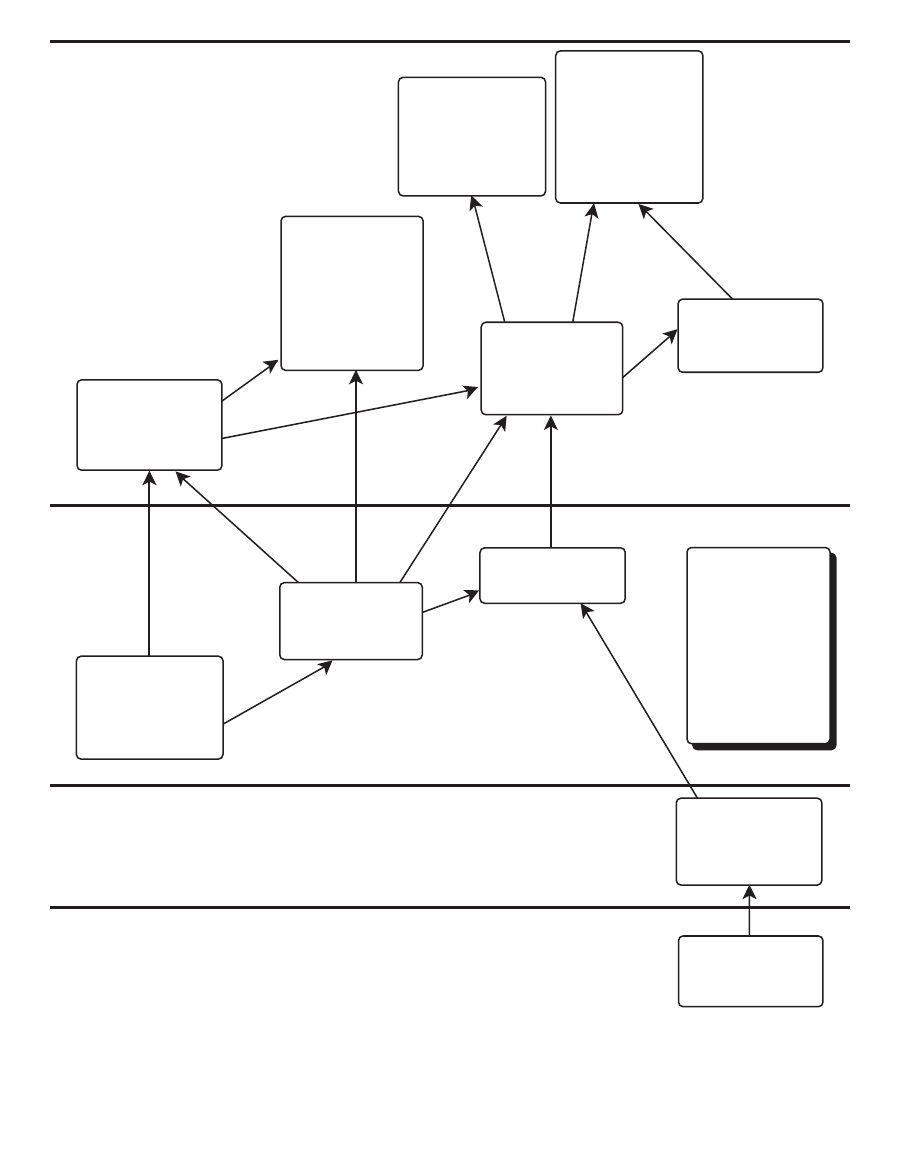
W h a t I s T h i s M a p ?
The map on page xi is a way of considering and organizing science
content standards. The map uses the learning goals (or parts of them) of the
American Association for the Advancement of Science’s Science for All Ameri-
cans (1989) and Benchmarks for Science Literacy (1993). Content standards from
the National Science Education Standards (NSES) (National Research Council
1996) overlap nearly completely with those goals. Arrows connecting the
goals imply that understanding one goal contributes to the understanding
of another. Goals that deal with the same idea are organized into vertical
“strands,” with more sophisticated goals above simpler ones. Descriptive
labels for the strands appear at the bottom of the map.
The science content on the map lists the ideas relevant to students’ un-
derstanding of electricity and magnetism that are both important and learn-
able. Your students may well learn more, but will learn better after the basic
science literacy described on the map has been achieved. This map traces
the ideal development of electricity and magnetism knowledge from kin-
dergarten to twelfth grade. Horizontal lines represent the level of grade
appropriateness.
Charging Ahead provides instructional methods that primarily achieve
learning goals for the map strand labeled “electromagnetic interactions.”
The map suggests what ideas students must have before trying to examine
the relationship between electricity and magnetism. Unit activities as pre-
sented may not be sufficient for students to become proficient with some of
the basic or extended ideas in the map strand; checking the progress of your
students along the way will help you see how to adapt instruction. Unit
activities may also touch on concepts outside of what the various science
standards consider essential for basic science literacy. Therefore, you may
decide to focus activities to make sure your core learning goals are achieved.
A Learning Map
on Electricity and
Magnetism

ix
CHARGING AHEAD: AN INTRODUCTION TO ELECTROMAGNETISM
H o w C a n I U s e t h e M a p ?
An Atlas map is designed to help clarify the context of the benchmark
or standard: where it comes from, where it leads, and how it relates to other
standards. With the map as a guide, you can make sure your students have
experience with the prerequisite learning, and you can actively draw stu-
dents’ attention to related content—getting their framework for learning
ready!
In addition to using the map to plan instruction, you may wish to an-
notate the map with common student misconceptions to address or com-
mon accurate conceptions that you can invoke to dispel these misconcep-
tions. Motivating questions that have worked for you, and phenomena to
illustrate points, may also find a place on your annotated map.
The map can help you connect your instruction to your state science
standards. As of this writing, 49 of the 50 states in the United States have
developed their own standards, most modeled directly on the National Sci-
ence Education Standards or the Benchmarks for Science Literacy. The correla-
tion between the NSES and Benchmarks in science content is nearly 100 per-
cent. So there is a unity of purpose and direction, if not quite a common
language. Fortunately, the National Science Foundation, the Council of Chief
State School Officers, and other groups have funded and developed websites
to guide educators in correlating these national standards with their state
goals (e.g., the ExplorAsource website at www.explorasource.com/educator. The
websites of many state departments of education also provide this correla-
tion service for educators.
The map can also provide a way to think about the design of student
assessment . The goal of your summative assessment is to determine whether
students can apply their learning to new situations—to show you, and to
show themselves, that they have a new tool for understanding.
A re T h e re O t h e r M a p s ?
These maps are being copublished by AAAS and NSTA in a new two-
volume work, Atlas of Science Literacy. The complete Atlas will contain nearly
100 similar maps on the major elementary and secondary basic science top-
ics: gravity, cell functions, laws of motion, chemical reactions, ratios and
proportionality, and more.
The connected learning goals displayed in Charging Ahead are only part
of a map that is—at the time of this printing—subject to revision. As addi-
tional maps are developed and tested, they will be linked to the Charging
Ahead page on the NSTA website and added to successive editions of Charg-
ing Ahead.

NATIONAL SCIENCE TEACHERS ASSOCIATION
x
M a p , A s s e s s m e n t , a n d t h e C o n s t r u c t i v i s t
P ro c e s s
Use the map as an aid to your constructivist teaching methods, allow-
ing students to recognize and integrate concepts—either those never learned
or those incompletely remembered—into the big picture of why these con-
cepts are useful to know.
Before you undertake any of the four activities in this book, it is impor-
tant to know whether your students have mastered the principles in the
map that lead to their current grade level. You may, for example, be sur-
prised to learn that some of your high school juniors do not really under-
stand that “magnets can be used to make some things move without being
touched,” a concept that, according to the strand map, should be mastered
by grade three. Students may also have a mix of true and false understand-
ings about electricity and magnetism as they begin the Charging Ahead ac-
tivities. It may be wise to ascertain—perhaps by having each student do a
“web” of everything he or she can think of about the term “magnetism”
and reviewing those webs—to ensure that all students are starting with the
basic information they need to build on in order to understand the concepts
presented in these activities.
Grades 6-8
Grades 3-5
Grades K-2
Moving electric charges
produce magnetic forces
and moving magnets
produce electric forces.
4G/H5
The interplay of electric
and magnetic forces is the
basis for electric motors,
generators, and many
other modern
technologies, including the
production of
electromagnetic waves.
4G/H5
Different kinds of materials
respond differently to
electric forces. In
conducting materials such
as metals, electric charges
flow easily, whereas in
insulating materials, such
as glass, they can move
hardly at all. 4G/H4
Vibrating electric charges
produce electromagnetic
waves around them.
4F/H3
Negative charges, being
associated with electrons,
are far more mobile in
materials than positive
charges are. 4G/H3
Electricity is used to
distribute energy quickly
and conveniently to
distant locations. 8C/M4
There are two kinds of
charges—positive and
negative. Like charges
repel one another,
opposite charges attract.
4G/H3
Without touching them, a
magnet pulls on all things
made of iron and either
pushes or pulls on other
magnets. 4G/E2
Magnets can be used to
make some things move
without being touched.
4G/P2
Electric currents and
magnets can exert a force
on each other. 4G/M3
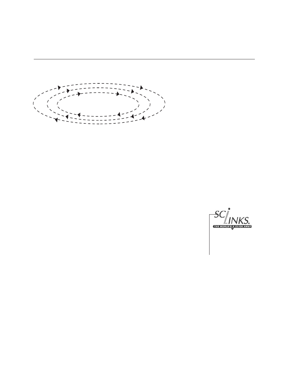
Electric currents circulating
in the Earth’s core give the
Earth an extensive
magnetic field, which we
detect from the orientation
of our compass needles.
SFAA p.56
Electric Charges
Strand
Electric Currents
Strand
Electromagnetic
Interactions Strand
Magnets Strand
ELECTROMAGNETISM
This map was adapted from
Atlas of Science Literacy (AAAS 2001). For more information, or to order, go to www.nsta.org/store.
Map Key
Codes
(e.g.,
4G/45)
SFAA
chapter, section,
and number of
corresponding
goal from
Benchmarks for
Science Literacy
(AAAS 1993)
concept from
Science for All
Americans
(AAAS 1989)
Grades 9-12
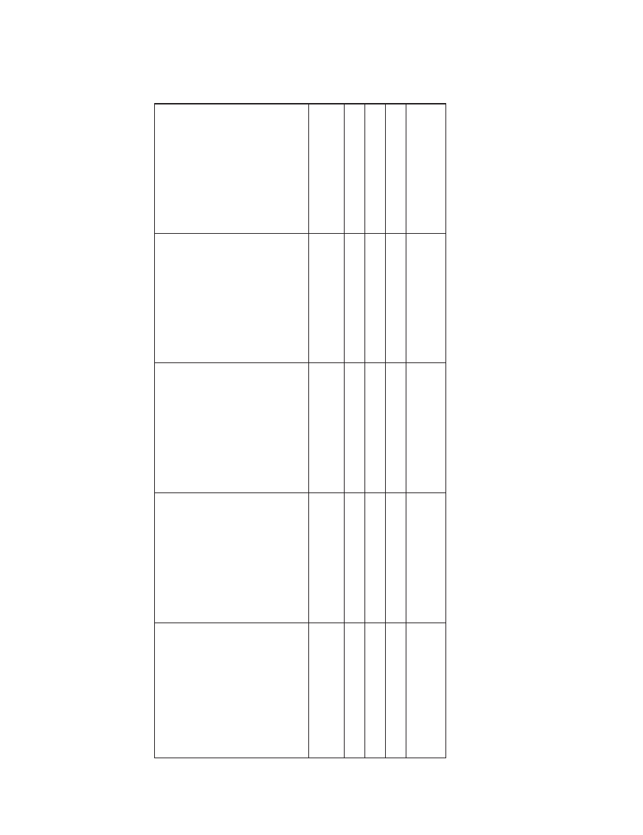
Guide to Relevant National Science Education Content Standar
d
s
Activity 1
Activity 2
Activity 3
Activity 4
Intr
oduces
the
Builds on student
Challenges
students
Challenges
students
Content
relationship between
understanding of
to constr
uct an electric
to construct a closed
Standard
*
electrical flow and
magnetism
and
motor using their
cir
cuit
(coil)
that
magnetism.
electrical
flow by
understanding
of
moves
thr
ough
a
showing how coils
electr
omagnetism.
magnetic
field to
in a curr
ent-carrying
pr
oduce or generate
wir
e af
fect the str
ength
electricity
.
of magnetic for
ces.
Unifying Concepts and
Pr
ocesses in Science
■■
■
■
Science as Inquiry
■■
■
■
Physical Science
■■
■
■
Science and T
echnology
■■
■
■
History and Natur
e
of Science
■
■
*Sour
ce: National Resear
ch Council. 1996.
National Science Education Standards.
W
ashington, DC: National
Academy Pr
ess,
pp.104-107.

Charging Ahead: An Introduction to Electromagnetism brings you sciLINKS, a new project that blends
the two main delivery systems for curriculum—books and telecommunications—into a dynamic
new educational tool for children, their parents, and their teachers. sciLINKS links specific science
content with instructionally rich Internet resources. sciLINKS represents an enormous opportu-
nity to create new pathways for learners, new opportunities for professional growth among teach-
ers, and new modes of engagement for parents.
In this sciLINKed text, you will find an icon near several of the concepts you are studying.
Under it, you will find the sciLINKS URL (www.scilinks.org) and a code. Go to the sciLINKS web-
site, sign in, type the code from your text, and you will receive a list of URLs that are selected by
science educators. Sites are chosen for accurate and age-appropriate content and good pedagogy.
The underlying database changes constantly, eliminating dead or revised sites or simply replacing
them with better selections. sciLINKS also ensures that the online content teachers count on re-
mains available for the life of this text. The sciLINKS search team regularly reviews the materials
to which this text points—revising the URLs as needed or replacing webpages that have disap-
peared with new pages. When you send your students to sciLINKS to use a code from this text,
you can always count on good content being available.
The selection process involves four review stages:
1
A cadre of undergraduate science education majors searches the World Wide Web for
interesting science resources. The undergraduates submit about 500 sites a week for
consideration.
2
Packets of these webpages are organized and sent to teacher-webwatchers with ex-
pertise in given fields and grade levels. The teacher-webwatchers can also submit
webpages that they have found on their own. The teachers pick the jewels from this
selection and correlate them to the National Science Education Standards. These pages
are submitted to the sciLINKS database.
3
Scientists review these correlated sites for accuracy.
4
NSTA staff approve the webpages and edit the information for accuracy and consis-
tent style.
sciLINKS is a free service for textbook and supplemental resource users, but obviously some-
one must pay for it. Participating publishers pay a fee to NSTA for each book that contains sciLINKS.
The program is also supported by a grant from the National Aeronautics and Space Administra-
tion (NASA).
xiii
CHARGING AHEAD: AN INTRODUCTION TO ELECTROMAGNETISM

NATIONAL SCIENCE TEACHERS ASSOCIATION
xiv
1
CHARGING AHEAD: AN INTRODUCTION TO ELECTROMAGNETISM
B a c k g ro u n d
When you create a closed circuit with a battery, electrons flow through
the wires, the bulb lights up and gets hot, and the wires and battery warm
up. Besides the chemical reactions going on inside the battery, is anything
else happening? It is hard to tell unless you can use some detection device.
In this investigation, you will use a compass to detect magnetism. You will
use the compass to investigate the relationship between electrical flow and
any magnetism that is produced from that flow.
C o n c e p t G o a l s
■
A current-carrying wire produces a magnetic effect (deflects a compass
needle) in the region around the wire. That magnetic effect is called
electromagnetism.
■
Electrons move along a wire from the negative end of the battery to the
positive end of the battery.
■
The direction of the electron flow in a wire determines the direction of
the magnetic field around the wire.
■
The strength of the magnetic influence (field) around a wire becomes less
at greater distances from the wire.
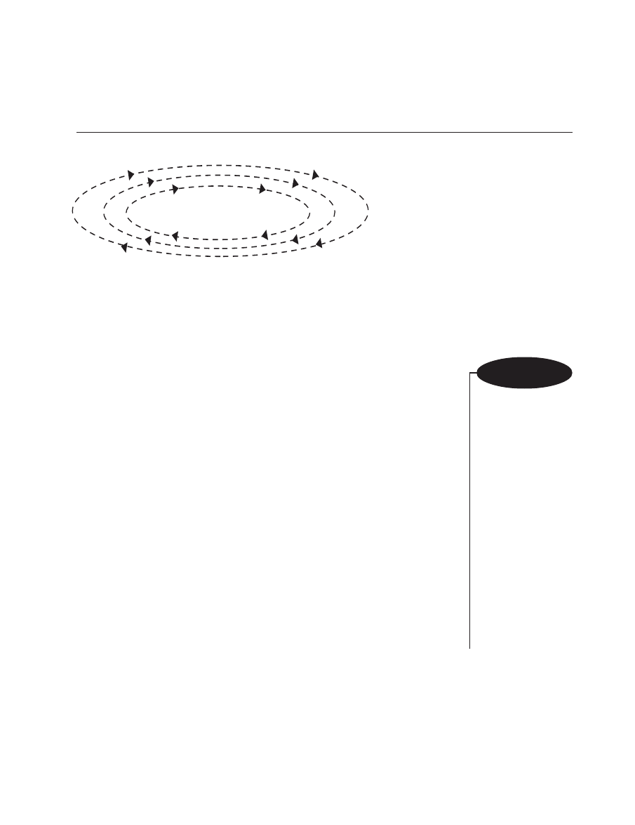
■
Magnetic fields (regions of magnetic influence) have direction and
“strength.”
■
The direction of the magnetic field at a particular point in space is the
direction a compass needle would point if the compass were located at
that point.
A c t i v i t y 1
S t u d e n t W o r k s h e e t
A Bonus from
Electrical Flow—Magnetism
Topic: electrical circuit
Go To:
Code: CH003
Topic: magnetic effect
Go To:
Code: CH004
NATIONAL SCIENCE TEACHERS ASSOCIATION
2
■
A left hand is an effective model for showing the relationship between
the direction of the magnetic field and the direction of electron flow.
P ro c e d u re
1
If you have not used a compass recently, you may want to refresh
your memory. The colored or pointed end of the needle usually points
approximately toward the Earth’s geographic north. Hold the compass
out in front of you, away from any metal objects, and note that the colored
or pointed end of the needle always points in the same direction, even
when you rotate the base or case of the compass.
Move your compass close to an iron or steel object and notice that the
compass needle is attracted to the object. It is important, therefore, to keep
the compass away from iron or steel objects when you are using it to detect
magnetism from other objects. Iron or steel under the desktops can influ-
ence the direction in which the compass needle points.
The compass needle is nothing more than a small, light magnet that
easily spins about its center when it interacts with other magnets. The
compass needle is attracted to iron and steel objects because the needle
itself causes those objects to become temporarily magnetized.
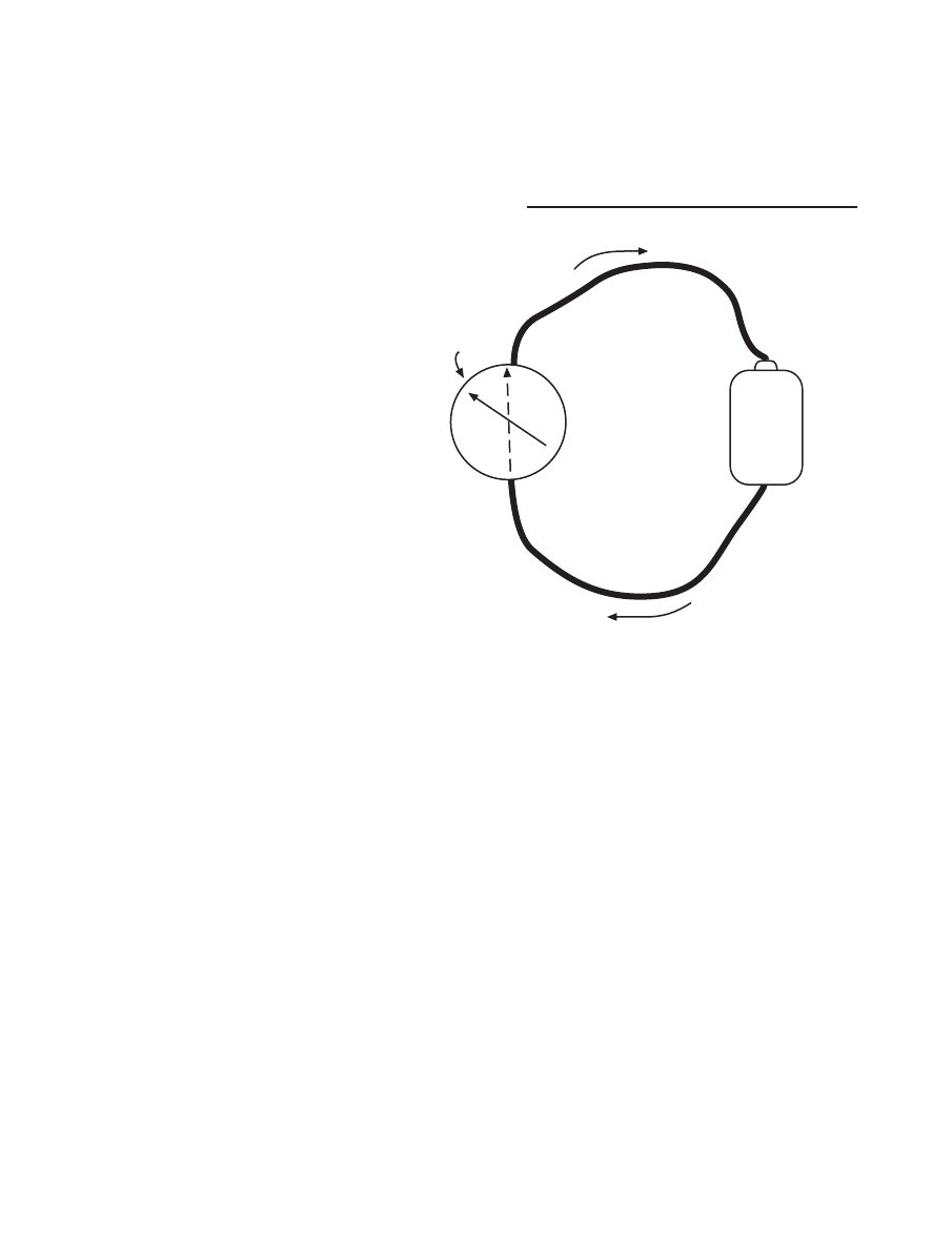
2
In 1820, Hans Christian Oersted, a Danish physicist and schoolteacher,
made the observation you are about to make. His discovery set the stage for
the development of many modern conveniences, including electrical mo-
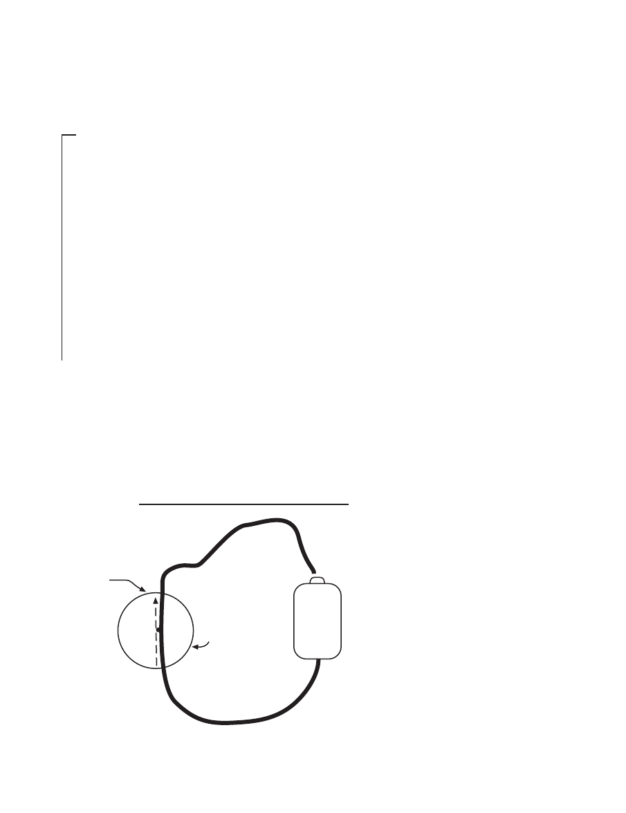
Compass
Wire on top of compass
Needle position when wire
is
not
connected
to battery
Battery
F i g u re 1 . 1
M a t e r i a l s
For each group:
■
one “D” battery (dry
cell) and one battery
holder
■
one directional,
magnetic compass
with a needle that is
free to move easily
without sticking
■
one 60-cm piece of
#24 enamel-coated
(insulated) wire (with
sanded ends) or #22
plastic-coated wire
(with stripped ends)
tors and the generation of electricity
from motion.
a
Place the compass on the table at
least 15 cm away from the bat-
tery. Connect one end of the wire
to the battery. Place the wire in a
straight line directly over the
compass and in line with the
needle. Briefly touch (no more
than two seconds) the other end
of the wire to the battery and ob-
serve what happens to the com-
pass needle.
Draw an arrow on the com-
pass illustration in Figure 1.1 to
show the direction of the needle
3
CHARGING AHEAD: AN INTRODUCTION TO ELECTROMAGNETISM
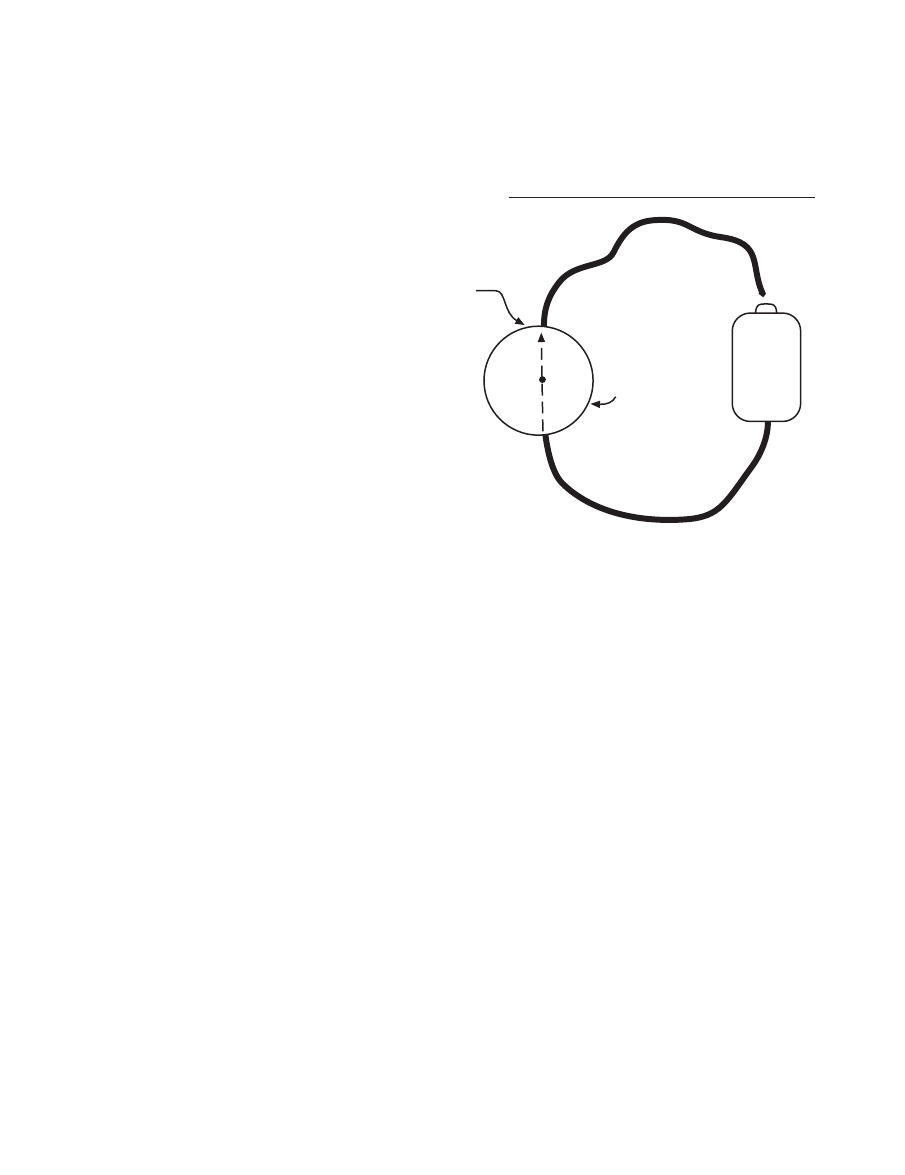
Compass
Wire beneath compass
Needle position when wire
is not connected
to battery
Battery
when a current-carrying wire is
on top of the compass. The
pointed end of the arrow repre-
sents the “north-seeking” end of
the needle. Also draw an arrow
on the wire showing the direction
in which the electrons are mov-
ing in the wire. Recall that elec-
trons move along a wire from the
negative end of the battery to the
positive end of the battery.
b
Repeat the above activity, but this
time place the wire under the
compass and align the wire with
the compass needle. Draw an ar-
row on the compass drawing
(Figure 1.2) to record the direc-
tion of the needle when a current-
carrying wire is under the compass. Also, draw an arrow showing the
direction of electron flow in the wire. Remember to keep the electricity
flowing in the wire for only two seconds.
c
Note the direction in which the needle moved (“deflected”) in 2b above.
With the wire under the compass and without changing the positions of
the compass or the wire, what can you do to make the deflected needle
point in the opposite direction? Describe your solution in the space
below.
d
It should be clear that a current-carrying wire is somehow creating a
magnetic influence in the space around it. What can you do to find out
how the “strength” of that influence changes with different distances
from the wire? Describe your solution, your conclusion about distance
and “strength,” and how your observations support your conclusion.
F i g u re 1 . 2

NATIONAL SCIENCE TEACHERS ASSOCIATION
4
e
A magnetic field is a region of space in which there is a magnetic influ-
ence. There is a magnetic field in the space around a magnet. A compass
can detect a magnetic field if the field is strong enough. Because the
compass needle is deflected in the region around the current-carrying
wire, you can conclude that there is________________________________
_____________________________________around a current-carrying
wire.
f
Magnetic fields have both “strength” and direction at each point in space.
The direction is the direction that a compass will point if it is held at that
point in space. The magnetic field both above and below a current-carry-
ing wire is: (circle 1 or 2)
1
in line with the wire.
2
across the wire.
g
To change the direction of the magnetic field above a wire, you would
have to change the __________________ of the electron flow in the wire.
Without moving the wire above the compass, you can do this by
______________________________________________________.
h
The magnetic field around a current-carrying wire is “stronger”: (circle
1 or 2)
1
closer to the wire.
2
farther away from the wire.
3
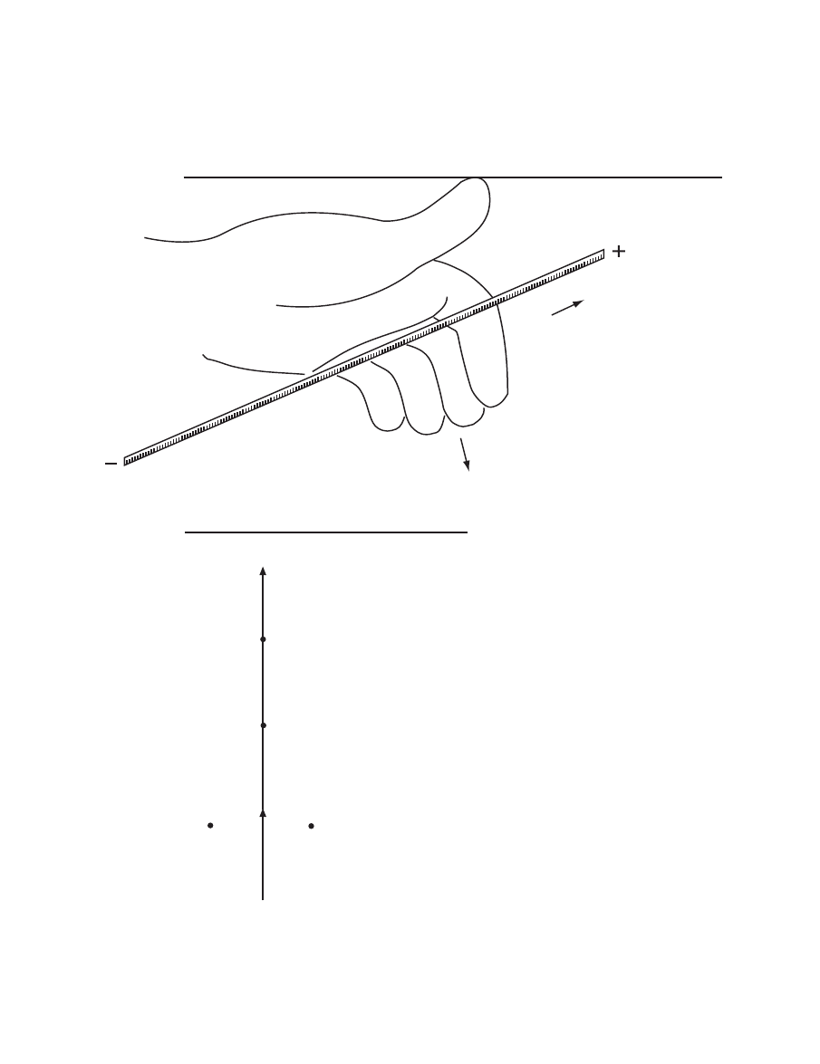
You can use your left hand as a model of the relationship between the
direction of the electron flow and the direction of the magnetic field (the
direction the compass would point) created by that flow.
5
CHARGING AHEAD: AN INTRODUCTION TO ELECTROMAGNETISM
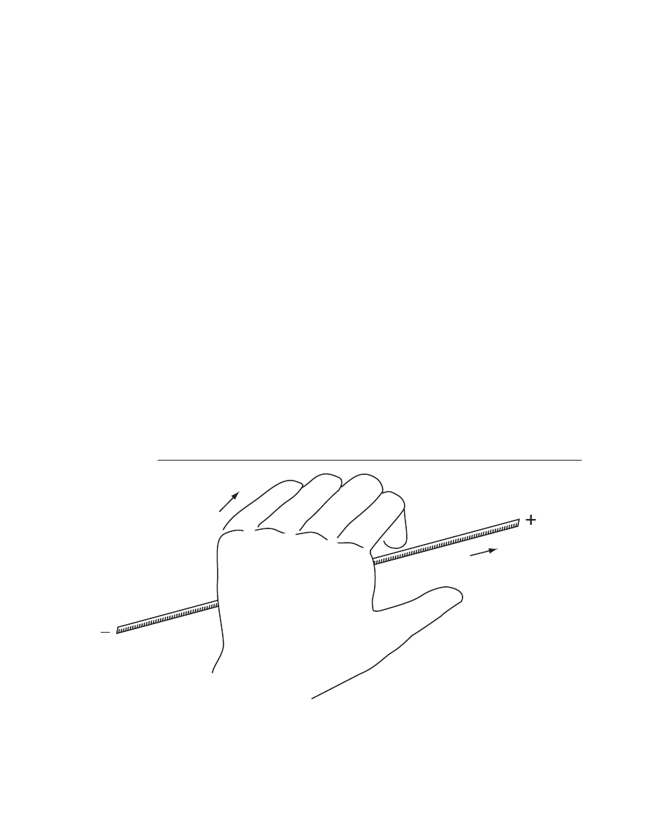
A L e f t - h a n d M o d e l
Pretend to grasp the wire with your left hand. Wrap your fingers around
the imaginary wire in such a way that your left thumb points in the direc-
tion of electron flow (Figure 1.3). Your fingers will then wrap around the
wire in the direction of the magnetic field. You can rotate your hand around
the wire to see which way your fingers point at any position around the
wire (Figure 1.4).
Practice using the left-hand model by answering the following ques-
tions associated with Figure 1.5. (circle the correct answer)
a
The magnetic field directly above the wire at “a” would point:
1
to the left.
2
to the right.
3
straight up out of the page.
4
straight down into the page.
Direction of
magnetic field
Direction of
electron flow
Left hand
F i g u re 1 . 3
NATIONAL SCIENCE TEACHERS ASSOCIATION
6
b
The magnetic field directly below
the wire at “b” would point:
1
to the left.
2
to the right.
3
straight up out of the page.
4
straight down into the page.
c
The magnetic field directly to the
left of the wire (neither above nor
below the wire) at “c” would
point:
1
to the left.
2
to the right.
3
straight up out of the page.
4
straight down into the page.
Wire
Field below wire?
Field above wire?
Field to the
right of wire?
Field to the
left of wire?
b
c
d
Electron flow in wire
a
F i g u re 1 . 5
Direction of
electron flow
Direction of magnetic field
Left hand
F i g u re 1 . 4
7
CHARGING AHEAD: AN INTRODUCTION TO ELECTROMAGNETISM
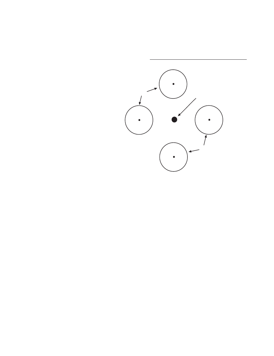
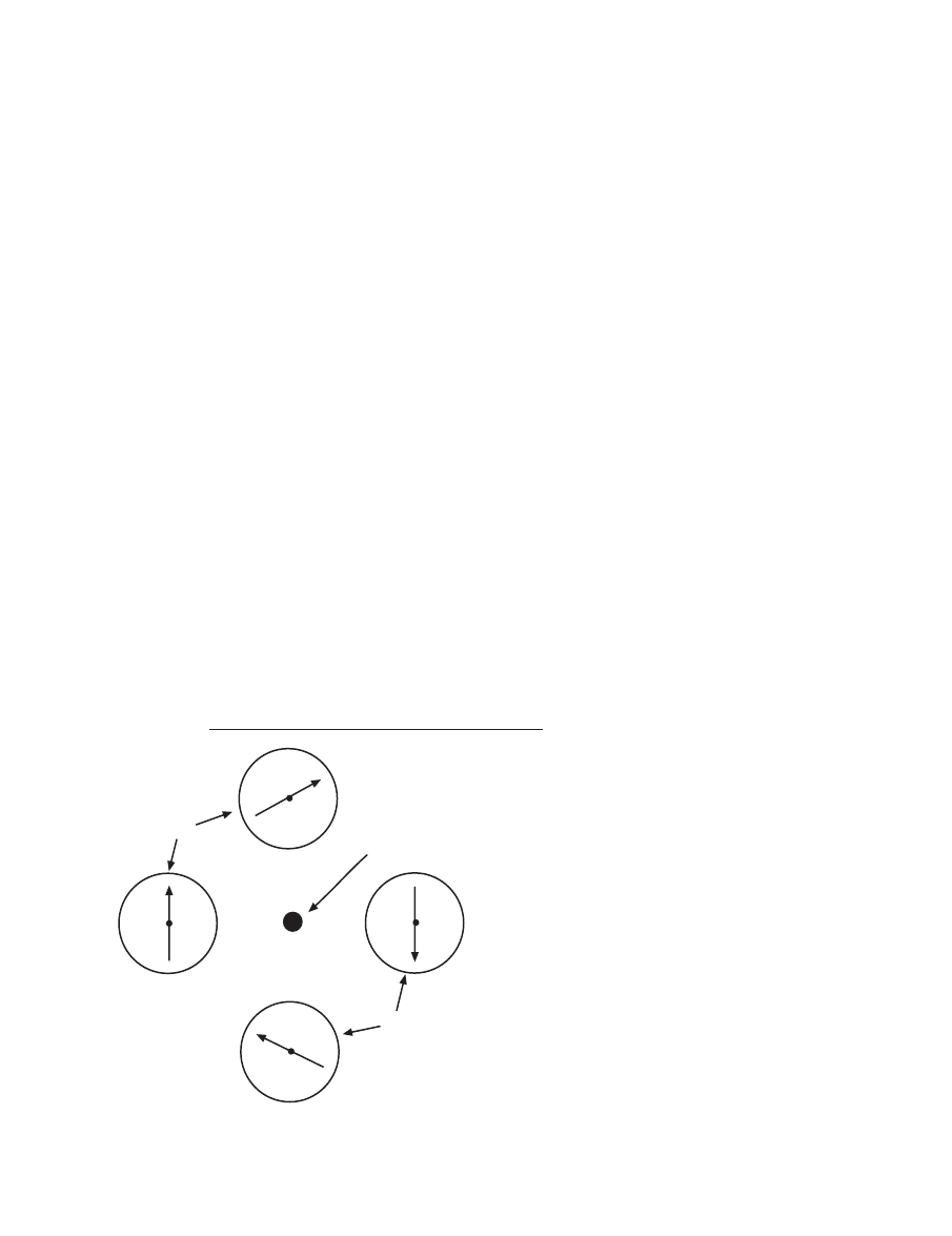
Compasses
End of wire
coming out of
page; electrons flow
along wire, up
and out of page
Compasses
F i g u re 1 . 6
d
The magnetic field directly to the
right of the wire (neither above
nor below the wire) at “d” would
point:
1
to the left.
2
to the right.
3
straight up out of the page.
4
straight down into the page.
e
Observe Figure 1.6 and assume
that the dot in the center is the
end of a wire that is coming out
of the page. Further assume that
electrons are flowing along that
wire out of the page directly up-
ward from the page. Use your
left-hand model to determine the
direction of the compass needle
(direction of the magnetic field) at each of the compass points around
the wire. Draw the compass needles in the four compasses and use the
pointed head of the arrow as the “north-seeking” end of the compass
needle.

NATIONAL SCIENCE TEACHERS ASSOCIATION
8
9
CHARGING AHEAD: AN INTRODUCTION TO ELECTROMAGNETISM
C a u t i o n
Short circuits are
created when the
wire is connected to
the ends of the bat-
tery. The short circuit
will heat up the wire
and quickly wear
down the battery.
Caution the students
to maintain a short
circuit for only a
couple of seconds at
a time. They can do
this by connecting
one end of the wire
to the battery and
briefly touching the
other end of the wire
to the battery.
T e a c h e r ’ s G u i d e T o
A c t i v i t y 1
A Bonus from
Electrical Flow—Magnetism
W h a t i s h a p p e n i n g ?
In this activity, students dis-
cover that a current-carrying wire
produces a magnetic field around it.
They use a compass to detect this
magnetic field, and they observe
that the direction of the field is
across the direction of the electron
flow. Furthermore, the students
learn that the field is “stronger”
closer to the wire. In addition, the
students learn that the direction of
the magnetic field at a point in space
is described as the direction the
north-seeking end of a compass
would point. Students can use their
left hands to model the relationship
between the direction of the electron
flow and the direction of the mag-
netic field it produces. Students
practice applying the model to dif-
ferent examples.
T i m e m a n a g e m e n t
One class period (40–60 minutes)
should be enough time to complete
the activity and discuss the results.
P re p a r a t i o n
Collect the materials listed on
page 2. Make sure that the batteries
are not dead, that the compasses
work, and that the ends of the wires
are stripped (plastic-coated wire) or
sanded (enamel-coated wire). If the
students have not worked with
enamel-coated wire, show them how
to use sand paper to sand off the
enamel from the ends of the wires.
Students may find that their com-
passes point in different directions
without any current-carrying wires or
magnetic materials nearby. Why don’t
all the compasses point north? Why
do the compasses point in different
NATIONAL SCIENCE TEACHERS ASSOCIATION
10
Wire on top of
compass
Drawn
needle
Electron flow
Electron flow
Compass
Battery
F i g u re 1 . 7
directions when they are moved
around on the desks or in the room?
Often the iron or steel in desks, filing
cabinets, walls, etc. influences the di-
rection of the compasses. For an ac-
curate “north reading,” a compass
must be away from all iron and steel
objects.
S u g g e s t i o n s f o r f u rt h e r
s t u d y
Challenge groups to get together
to see what happens when two cur-
rent-carrying wires are held in line
with a compass needle. Students
should discover that when both
wires carry electrons in the same di-
rection over and in line with a com-
pass needle, the needle deflection is
greater than when just one wire is
used. Students also should discover
that when the wires carry electrons
in opposite directions over and in line
with the compass needle, the needle
deflection is less because the mag-
netic fields exert forces on the needle
in opposite directions.
Students have studied direct cur-
rent electricity where the electrons
move in one direction in the conduc-
tor. Alternating current electricity is
used in our homes. The electrons in
the alternating currents switch direc-
tions 60 times each second. If this elec-
tron jiggling is going on in the wires
in our homes, what is happening to
the magnetic field surrounding those
wires? Have students consider this
question and guide them to under-
stand that the magnetic field around
the wires in our homes must be jig-
gling or changing directions 60 times
each second. When held near a cur-
rent-carrying house wire, a typical
compass needle does not show deflec-
tion. The inertia of the needle prevents
the needle from changing directions
60 times each second. Just as the
needle begins to move in one direc-
tion, it is forced in the opposite direc-
tion.
Answers
to questions found within
Procedure on pages 2–7.
2a. Draw an arrow on the compass in
Figure 1.1 to show the direction of
the needle when a current-carrying
wire is on top of the compass. Also
draw an arrow showing the direction
of electron flow in the wire.
One answer is shown in Figure
1.7. If the terminals of the battery
11
CHARGING AHEAD: AN INTRODUCTION TO ELECTROMAGNETISM
F i g u re 1 . 8
wire and compass are closer. As-
suming that more deflection
means a “stronger” interaction,
the conclusion is that the mag-
netic influence is “stronger”
closer to the wire.
2e. When a compass needle is deflected
in the region around a current-car-
rying wire, you can conclude that
there is a magnetic field around the
wire.
2f. The magnetic field both above and
below a current-carrying wire is: (1)
in line with the wire or (2) across the
wire?
(2) across the wire.
2g. To change the direction of the
magnetic field above a wire, you
would have to change the direction
Compass
Electron flow
Electron flow
Drawn
needle
Wire beneath
compass
Battery
were reversed, the drawn arrow
would be deflected to the other
side of the wire.
2b. Draw an arrow on the compass in
Figure 1.2 to record the direction of
the needle when a current-carrying
wire is under the compass. Also,
draw an arrow showing the direction
of electron flow in the wire.
One answer is shown in Figure
1.8. If the terminals of the battery
were reversed, the drawn arrow
would be deflected to the other
side of the wire.
2c. Note the direction in which the needle
moved (“deflected”) in 2b above. With
the wire under the compass and with-
out changing the positions of the com-
pass or the wire, what can you do to
make the deflected needle point in the
opposite direction?
The solution is to keep the wires
and compass the same, but
switch wires on the terminals of
the battery. This sends the elec-
trons in the opposite direction
through the wire.
2d. What can you do to find out how the
“strength” of the magnetic influence
around the current-carrying wire
changes at different distances from
the wire? Describe your solution,
your conclusion about distance and
“strength,” and how your observa-
tions support your conclusion.
Change the distance between the
current-carrying wire and com-
pass. Note that there is greater de-
flection in the compass when the
NATIONAL SCIENCE TEACHERS ASSOCIATION
12
of the electron flow in the wire. With-
out moving the wire above the com-
pass, you can do this by switching
the ends of the wire on the termi-
nals of the battery.
2h. The magnetic field around a current-
carrying wire is “stronger”: (1)
closer to the wire or (2) farther away
from the wire.
(1) closer to the wire.
3a. The magnetic field directly above the
wire at “a” would point: (1) to the
left, (2) to the right, (3) straight up
out of the page, or (4) straight down
into the page.
(1) to the left.
3b. The magnetic field directly below the
wire at “b” would point: (1) to the
left, (2) to the right, (3) straight up
out of the page, or (4) straight down
into the page.
(2) to the right.
3c. The magnetic field directly to the left
of the wire (neither above nor below
the wire) at “c” would point: (1) to
the left, (2) to the right, (3) straight
up out of the page, or (4) straight
down into the page.
(4) straight down into the page.
3d. The magnetic field directly to the
right of the wire (neither above nor
below the wire) at “d” would point:
(1) to the left, (2) to the right, (3)
straight up out of the page, or (4)
straight down into the page.
(3) straight up out of the page.
3e. Observe Figure 1.6 and assume that
the dot in the center is the end of a
wire that is coming out of the page and
that electrons are flowing along that
wire directly upward from the page.
Use the left-hand model to determine
the direction of the compass needle at
each of the compass points around the
wire. Draw the compass needles in the
compasses; use the pointed head of the
arrow as the “north-seeking” end of
the compass needle.
The compass directions are
shown in Figure 1.9.
Compasses
Compasses
End of wire
coming out of
page; electrons flow
along wire, up and
out of page
F i g u re 1 . 9
N o t e :
The left-hand model is the same
as the right-hand rule found in physics
textbooks. Here, the direction of electron
flow is used. The right-hand rule uses
current direction (positive charge flow).
13
CHARGING AHEAD: AN INTRODUCTION TO ELECTROMAGNETISM
A c t i v i t y 2
S t u d e n t W o r k s h e e t
Coils and
Electromagnets
B a c k g ro u n d
Hans Christian Oersted was probably very excited about his discovery
that a current-carrying wire produces a magnetic effect in the region around
that wire. Perhaps he realized that current-carrying wires could produce
very strong magnetism that may be able to exert forces to turn wheels
and accomplish work. All of modern day electric motors depend on the
production of magnetism from current-carrying wires. In this activity, you
will investigate how to make the magnetism from current-carrying wires
stronger. In the next activity you will use an electromagnet to make an elec-
tric motor.
C o n c e p t G o a l s
■
A coil of wire that carries a current produces a stronger magnetic field
than just a straight wire that carries the same current.
■
A piece of iron (e.g., a nail) placed in a coil that carries a current will
become magnetized by the coil.
■
A piece of magnetized iron in a coil that carries a current will produce a
stronger magnetic field than just the coil alone.
■
An electromagnet is a magnet that is produced by a coil that carries an
electrical current.
Topic: electromagnet
Go To:
Code: CH005
NATIONAL SCIENCE TEACHERS ASSOCIATION
14
Briefly touch wire
to battery terminal
Straws
V shaped
paper clip
M a t e r i a l s
For each group:
■ one “D” battery (dry
cell) and one battery
holder
■ one 80-cm piece of
enamel-coated
(insulated) wire (with
sanded ends) or bell
wire (with stripped
ends)
■ one 20-cm piece of
enamel-coated
(insulated) wire (with
sanded ends) or bell
wire (with stripped
ends)
■ three plastic drinking
straws
■ two pieces of masking
tape
■ one large, steel paper
clip (4.8 cm x 1 cm)
■ twenty large, steel
paper clips chained
together
■ one steel or iron nail
(8–10 cm long )
■ one beaker, or a foam
or plastic cup
■ one light bulb in its
socket
■ scissors
■
The strength of an electromagnet increases as the number of wraps in the
coil increases.
■
The strength of an electromagnet decreases as the electrical current in the
coil decreases.
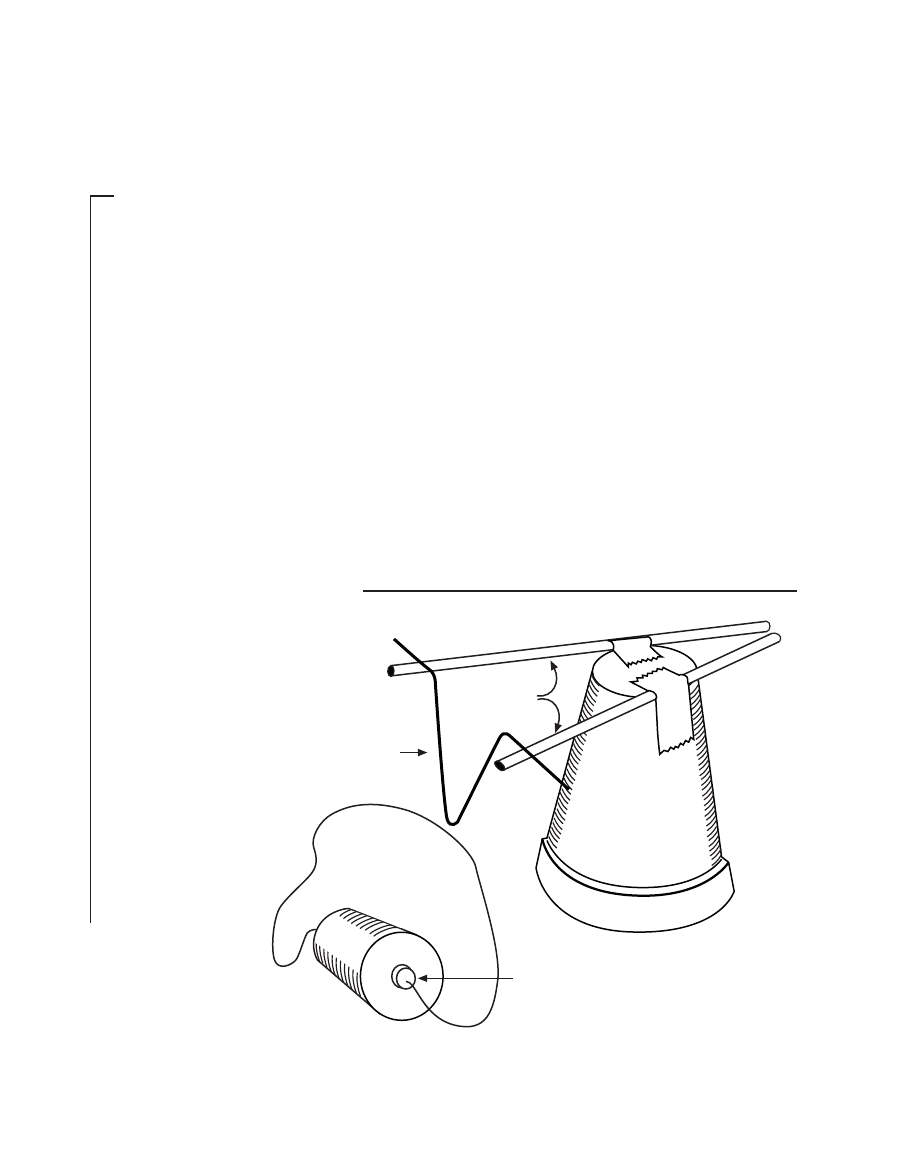
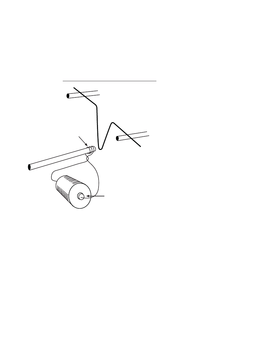
P ro c e d u re
1
In the last activity, you deflected a compass needle with a current-car-
rying wire. Because a current-carrying wire acts like a magnet (it produces
a magnetic effect in the region around it), perhaps the wire will attract iron
objects just as a regular permanent magnet does.
a
Tape two plastic drinking straws to the bottom of an overturned cup or
beaker. The ends of the straws should be about 8 cm apart. Open the
large paper clip and bend it into a “V” shape as shown below. Place the
“V” shaped paper clip on the “arms” of the drinking straws so that it
easily moves back and forth (Figure 2.1).
F i g u re 2 . 1
15
CHARGING AHEAD: AN INTRODUCTION TO ELECTROMAGNETISM
b
Attach one end of the 80-cm wire to one end of the battery. Use your
fingers to stop the paper clip from swinging back and forth. Move the
wire very near the bottom part of the “V” (again, see Figure 2.1). Don’t
touch the paper clip. When the wire is very close to the stationary paper
clip, briefly touch the other end of the wire to the battery to send a cur-
rent through the wire. Is the paper clip attracted to the current-carrying
wire? Write your answer below.
c
Starting about 8 cm from one end of the wire, wind the wire around
your index finger. Be careful not to wind too tightly. Stop winding when
you are about 8 cm from the other end of the wire and slip the coil of
wire off your finger. Keep the coil together.
Attach one end of the wire to one end of the battery. Again use your
fingers to stop the paper clip from swinging back and forth. Move the
coil very near the bottom part of the “V.” Don’t touch the paper clip.
When the coil is very close to the stationary paper clip, briefly touch the
other end of the wire to the battery to send a current through the coil. Is
the paper clip attracted to the current-carrying coil? How does the coil’s
attraction compare to the attraction of a single strand of wire? Write
your answers below.
d
Disconnect the wire from the battery and unwrap the coil of wire. Do
not pull on the ends of the wire to straighten out the coil; this will
produce a kinky mess.
Next, starting about 8 cm from the end of the wire, wrap the wire around
a drinking straw (Figure 2.2). Try to keep all the coils within a 1-cm
section of the straw. Keep the coil rather tight but do not wrap so tightly
C a u t i o n
A short circuit is
created when the
wire is attached to
the battery. The
wire gets hot. Do
not allow the ends
of the wire to touch
the battery for more
than two seconds
at a time.
NATIONAL SCIENCE TEACHERS ASSOCIATION
16
that the straw is crushed. Stop wrapping when there are about 8 cm of
wire left. Next, use the scissors to cut one end of the straw close (0.3 cm)
to the coil.
Connect one end of the wire to
one of the battery terminals. Stop
the “V” from moving. Move the
coil near the end of the bottom of
the “V.” Briefly touch the other
end of the wire to the other
terminal of the battery to send a
current through the coil. Describe
below the extent to which the cur-
rent-carrying coil attracts the “V”
paper clip.
F i g u re 2 . 2
Briefly touch wire to
battery terminal
Coil around
end of straw
Next, place the nail into the end of the straw near the coil. Hold the head
of the nail near the “V” and briefly send a current through the coil. How
does the coil-and-nail’s attraction of the “V” compare to the coil’s at-
traction alone? Write your answer below.
2
When you wrap an insulated current-carrying wire around an iron or
steel object, you create an electromagnet. As you found in step 1d above,
the iron or steel can greatly increase the magnetic force exerted on nearby
objects. The magnetism created by the coil turns the nail into a temporary
magnet. For electromagnets to be of any use, they must be able to create
rather large magnetic forces. The question arises: How can we increase the
strength of an electromagnet?
17
CHARGING AHEAD: AN INTRODUCTION TO ELECTROMAGNETISM
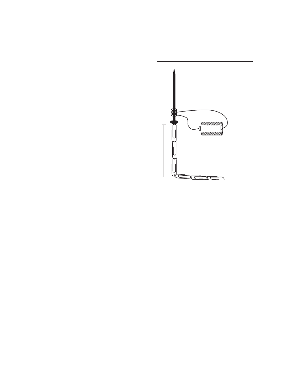
Challenge:
Use the nail, the bat-
tery, and the chain of 20 paper
clips to investigate how the num-
ber of coils wrapped around the
nail determines the strength of
the electromagnet (the number of
paper clips lifted off the table).
Keep the coils near the head of
the nail.
Stretch out the chain of paper
clips on the table.
Use the head of the nail to pick
up the first paper clip in the
chain. Smoothly move the nail
(with the first paper clip at-
tached) over the second paper
clip and try to pick two paper
clips off the table (Figure 2.3).
Keep moving down the chain to
see how many paper clips the
electromagnet will pick off the
Three paper
clips
lifted off
tabletop
F i g u re 2 . 3
table. Keep the nail vertical and in line with the string of paper clips that
have been picked off the table.
Now wrap some more coils around the nail and follow the same steps
as above.
Conclusion:
In the space below, describe the relationship between
the number of coils in an electromagnet and the strength of the
electromagnet.
NATIONAL SCIENCE TEACHERS ASSOCIATION
18
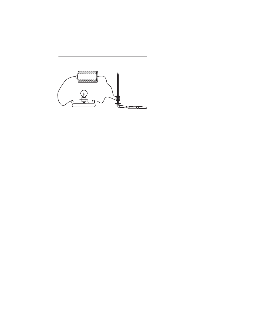
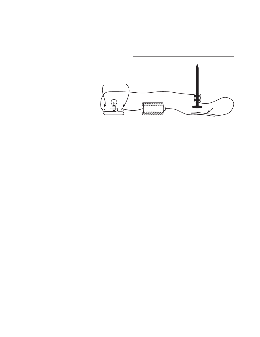
3
Construct an electromagnet that
will consistently pick up at least three
paper clips from a chain of paper
clips on the tabletop.
Next, place a light bulb and
socket in the circuit, as shown in Fig-
ure 2.4. Use the electromagnet to try
to pick up at least three paper clips
along the chain.
a
Describe below how the bulb in
the circuit with the electromag-
net influenced the strength of the
electromagnet.
F i g u re 2 . 4
Bulb in the circuit
with the electromagnet
b
When the bulb was placed in the circuit with the electromagnet, the
bulb provided resistance to the flow of electricity and caused the electri-
cal flow to be reduced in all parts of the circuit. In other words, the bulb
reduced the rate of electrical flow or current through the electromagnet.
How does the current (rate of electrical flow) in an electromagnet deter-
mine the strength of the electromagnet?

19
CHARGING AHEAD: AN INTRODUCTION TO ELECTROMAGNETISM
S u m m a r i z e
c
List the factors found in this activity that influence the strength of an
electromagnet.
d
Describe the relationship between each factor and the strength of the
electromagnet.

NATIONAL SCIENCE TEACHERS ASSOCIATION
20
21
CHARGING AHEAD: AN INTRODUCTION TO ELECTROMAGNETISM
W h a t i s h a p p e n i n g ?
In this activity, students learn
that a current-carrying wire is not
only able to show magnetic effects by
deflecting compass needles, but, like
regular, permanent magnets, it is able
to attract iron and steel objects. Ad-
ditionally, students discover that
magnetic forces increase when the
number of wraps, coils, or windings
in an electromagnet increases and
when the current in the coils in-
creases.
T i m e m a n a g e m e n t
One or two class periods (40–60
minutes each) should be enough time
to complete the activity and discuss
the student responses.
P re p a r a t i o n
Collect the materials listed on
page 14. Make sure that the ends of
the wires are sanded or stripped.
Also, because the batteries must be
T e a c h e r ’ s G u i d e T o
A c t i v i t y 2
Coils and
Electromagnets
C a u t i o n
The students will
be creating short
circuits with their
electromagnets and
there is a danger
that the wires and
battery will get hot.
Remind the stu-
dents to disconnect
their batteries from
the electromagnet
as soon as they
have made an
observation or as
soon as the wire
begins to get warm.
rather “strong” for this activity, the
batteries should be checked. If the
batteries are weak, it may be neces-
sary to provide each group with two
batteries hooked up in series.
S u g g e s t i o n s f o r
f u rt h e r s t u d y
Electromagnets are used in
many different places throughout the
home. There are electromagnets in
every electric motor (e.g., disk, CD,
and tape drives; can openers; fans;
electric toothbrushes; garage door
openers). Electromagnets also are
used in sound speakers (e.g., head-
sets, phones, radios).
There are electromagnets that
protect our homes from fires that are
caused by overheated wires in elec-
trical systems. The protection devices
are called circuit breakers, and they
break or open circuits when the cur-
rent becomes great enough to heat
the wires to dangerous temperatures.
Figures 2.5 and 2.6 show the basic
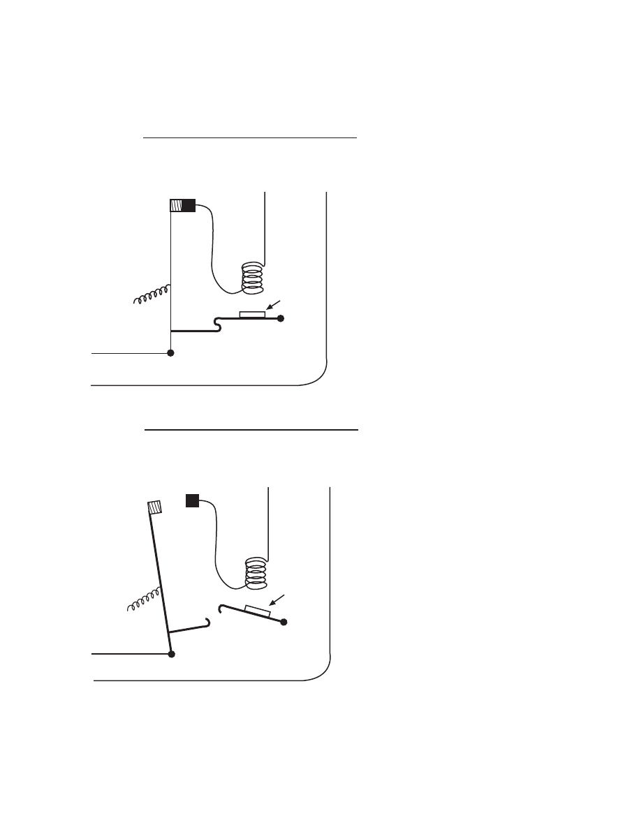
NATIONAL SCIENCE TEACHERS ASSOCIATION
22
workings of the circuit breaker. The
more current that runs through the
circuit, the stronger the pull of the
electromagnet (e). If the current gets
too high, the electromagnet becomes
strong enough to pull open lever A.
This allows lever B to spring back-
ward and open the circuit at 1 and 2.
To reset the switch, lever B has to be
pushed back to where it connects
with lever A and closes the circuit at
1 and 2.
Challenge
: Have students create
their own circuit breakers using
batteries, bulbs, wires, nails, tape,
paper clips, etc. They can test
their circuit breakers by shorting
around the bulb in the circuit. To
short around the bulb, use a 20-
cm wire to connect the two ter-
minals of the bulb holder
(Figure 2.7). The short should
greatly increase the current and
the increased current should
strengthen the electromagnet that
pulls open the switch and breaks
the circuit.
However, as soon as the circuit
is opened, the electromagnet
should stop pulling. Without the
pull of the electromagnet, the
circuit may close again. If the
circuit does close again, the
electromagnet will turn on and
reopen the circuit. This circuit,
which repeatedly opens and
closes, is the type of circuit found
in doorbell buzzers.
Because it would be unwise to al-
low a circuit breaker to close the
Circuit breaker
closed
1 2
e
Iron
A
B
To power
To power
Spring
To rest of circuit
To rest of circuit
1
2
e
Iron
A
B
To power
To power
Spring
Circuit breaker
open
To rest of circuit
To rest of circuit
F i g u re 2 . 6
F i g u re 2 . 5
23
CHARGING AHEAD: AN INTRODUCTION TO ELECTROMAGNETISM
circuit immediately after
breaking it, the student in-
ventors will have to design
a way to keep the circuit
open once the electromag-
net opens the circuit and
turns off the electromagnet.
In real circuit breakers, the
electromagnet pulls on a
trigger that releases a
spring-loaded switch. The
spring holds the switch
open until it is reset.
Answers
to questions found within
Procedure on pages 14–19.
1b. Attach one end of the 80-cm wire to
one end of the battery. Move the wire
very near the bottom part of the “V”
of the paper clip. Briefly touch the
other end of the wire to the battery
to send a current through the wire.
Is the paper clip attracted to the cur-
rent-carrying wire?
If the batteries are new, students
may see a very slight movement
of the paper clip. Most likely the
magnetic force from one strand
of wire will not be great enough
to move the paper clip.
1c. Attach one end of the wire to one end
of the battery. Move the coil very
near the bottom part of the “V” of
the paper clip. Briefly touch the other
end of the wire to the battery to send
a current through the coil. Is the
paper clip attracted to the current-
carrying coil? How does the coil’s
attraction compare to the attraction
of a single strand of wire?
The coil should attract the paper
clip, but not strongly. The attrac-
tion from the coil, however,
should be greater than the attrac-
tion from just one strand of wire.
1d. Connect one end of the wire to one
of the battery terminals. Move the
coil near the end of the bottom of the
paper clip “V.” Briefly touch the
other end of the wire to the other ter-
minal of the battery to send a cur-
rent through the coil. Describe the
extent to which the current-carrying
coil attracts the paper clip.
The coil wrapped on the drink-
ing straw should slightly attract
the paper clip.
Next, place the nail into the end of
the straw near the coil. Hold the head
of the nail near the “V” and briefly
send a current through the coil. How
does the coil-and-nail’s attraction of
the “V” compare to the coil’s attrac-
tion alone?
Iron
Short here
F i g u re 2 . 7

NATIONAL SCIENCE TEACHERS ASSOCIATION
24
The nail placed inside the straw
and coil should produce a signifi-
cantly greater attraction than the
coil alone.
2. How can we increase the strength of
an electromagnet?
As the number of coils or wind-
ings increases, the strength of the
electromagnet increases. (The
number of paper clips picked up
by the electromagnets also de-
pends on whether the battery is
in good condition or not.)
3a. Describe how the bulb in the circuit
with the electromagnet influenced
the strength of the electromagnet.
When a bulb is placed in the cir-
cuit with an electromagnet, the
strength of the magnet decreases.
3b. How does the current (rate of elec-
trical flow) in an electromagnet de-
termine the strength of the electro-
magnet?
Lesser current produces a weaker
electromagnet. A greater current
produces a stronger electromagnet.
3c. List the factors found in this activ-
ity that influence the strength of an
electromagnet.
The primary factors that influ-
ence the strength of an electro-
magnet are the number of coils
and the rate of electrical flow
(current).
3d. Describe the relationship between
each factor listed above and the
strength of the electromagnet.
Increases in either will result in a
stronger electromagnet. Also, an
iron core (such as a nail) inside a
coil greatly increases the strength
of magnetism.
25
CHARGING AHEAD: AN INTRODUCTION TO ELECTROMAGNETISM
Topic: mag-lev trains
Go To:
Code: CH006
Topic: MRI
Go To:
Code: CH007
T E C H N O L O G I C A L T I E - I N
M a g - l e v Tr a i n s a n d M R I s
Electromagnets are used in some of the newest technology being de-
veloped today. One project is the development of mag-lev (“magnetic levi-
tation”) trains. These trains do not ride on wheels; in fact the train does
not even touch the track. Strong electromagnets keep the train near the
track but off the track. Strong electromagnets also propel the train down
the track. Without the friction of rolling wheels on hard track, the mag-
lev trains will be able to travel faster (300 miles per hour) and with less
energy and less pollution than the trains of today.
Magnets attract iron objects and attract or repel other magnets with-
out touching them. Levitation occurs when an object is held up without
touching another object. When magnets are involved in producing levita-
tion, we call that “magnetic levitation.” Mag-lev trains hold up and pro-
pel the train with electromagnets.
Ordinary electromagnets would not be strong enough to run mag-
lev trains and would require a great deal of energy. Superconductors are
used in making the very strong magnets needed to run mag-lev trains.
Superconductors are materials that have no electrical resistance to the flow
of electricity. Without electrical resistance, very strong magnets can be
produced. Certain materials become superconductors at very low tem-
peratures. The materials have to be kept cold and this requires energy.
Scientists and engineers are working hard to create materials that become
superconductors at higher temperatures.
MRI (magnetic resonance image) machines are used in hospitals to
take very detailed pictures of tissues inside the body. These machines make
images by producing strong magnetic fields through which the body
moves. The strong magnetic fields are produced by strong electromag-
nets that are made with superconducting coils. These machines help doc-
tors diagnose and treat disease. Again, electromagnets are used in new
ways that improve our lives.

NATIONAL SCIENCE TEACHERS ASSOCIATION
26
27
CHARGING AHEAD: AN INTRODUCTION TO ELECTROMAGNETISM
A c t i v i t y 3
S t u d e n t W o r k s h e e t
Making an
Electric Motor—
Electromagnetism in Action
B a c k g ro u n d
The last activity focused on electromagnetism and factors that deter-
mine the strength of magnetic interaction. Scientists and engineers have
used their knowledge of electromagnets to create simple electromagnetic
devices (doorbells, switches, circuit breakers, sound speakers, etc.) that are
very much a part of our everyday lives. One of the more complex, ingen-
ious, and useful devices is the electric motor. Electric motors are all around
us, turning VCR tapes, CDs, computer disk drives, can openers, tooth-
brushes, refrigerator and air conditioner pumps, drills, saws, fans, and more.
Each electric motor turns because of electromagnets and electromagnetic
interaction. In this activity, you will build an electric motor out of common
materials, including plastic drinking cups, wire, batteries, plastic drinking
straws, and magnets. Although the motor you build will not be able to ac-
complish much, it should provide you with a basic understanding of how
real electric motors work. You will learn that “timing is everything.” Fur-
thermore, as you persist in getting your motor to work, you may under-
stand better the persistence and problem solving required to create a useful
product that works reliably.
Your teacher will either provide you with the rotor, flopper switch, and
penny switch for this activity or guide you through constructing them.
Topic: electric motor
Go To:
Code: CH008
NATIONAL SCIENCE TEACHERS ASSOCIATION
28
M a t e r i a l s
For each group:
For Part 1—the
“strobe” light
■ one rotor on its stand
(see Figure 3.1)
■ one flopper (with
washer) (to make a
flopper, see page 42)
■ one penny switch
(with wires attached)
(to make a penny
switch, see page
39–42)
■ two 1.5-volt dry cells
in dry cell holders
■ one light bulb in a
socket
■ two 15-cm wires
■ masking tape
C o n c e p t G o a l s
■
An electric motor can be built from available simple materials (magnets,
wire, batteries, cups, etc.).
■
Electric motors work because of the interaction between electromagnets
or because of the interaction between electromagnets and permanent
magnets.
■
Rotors are what move in motors and the rotors are pushed around be-
cause the magnets on them interact with other magnets in the motor.
■
For electric motors to work, electromagnets must turn on and off at just
the right times.
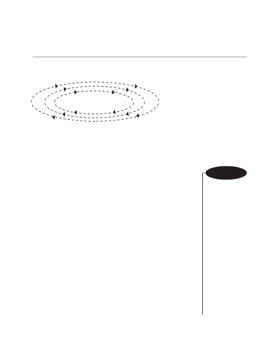
P a rt 1 — B u i l d i n g a “ S t ro b e ” L i g h t
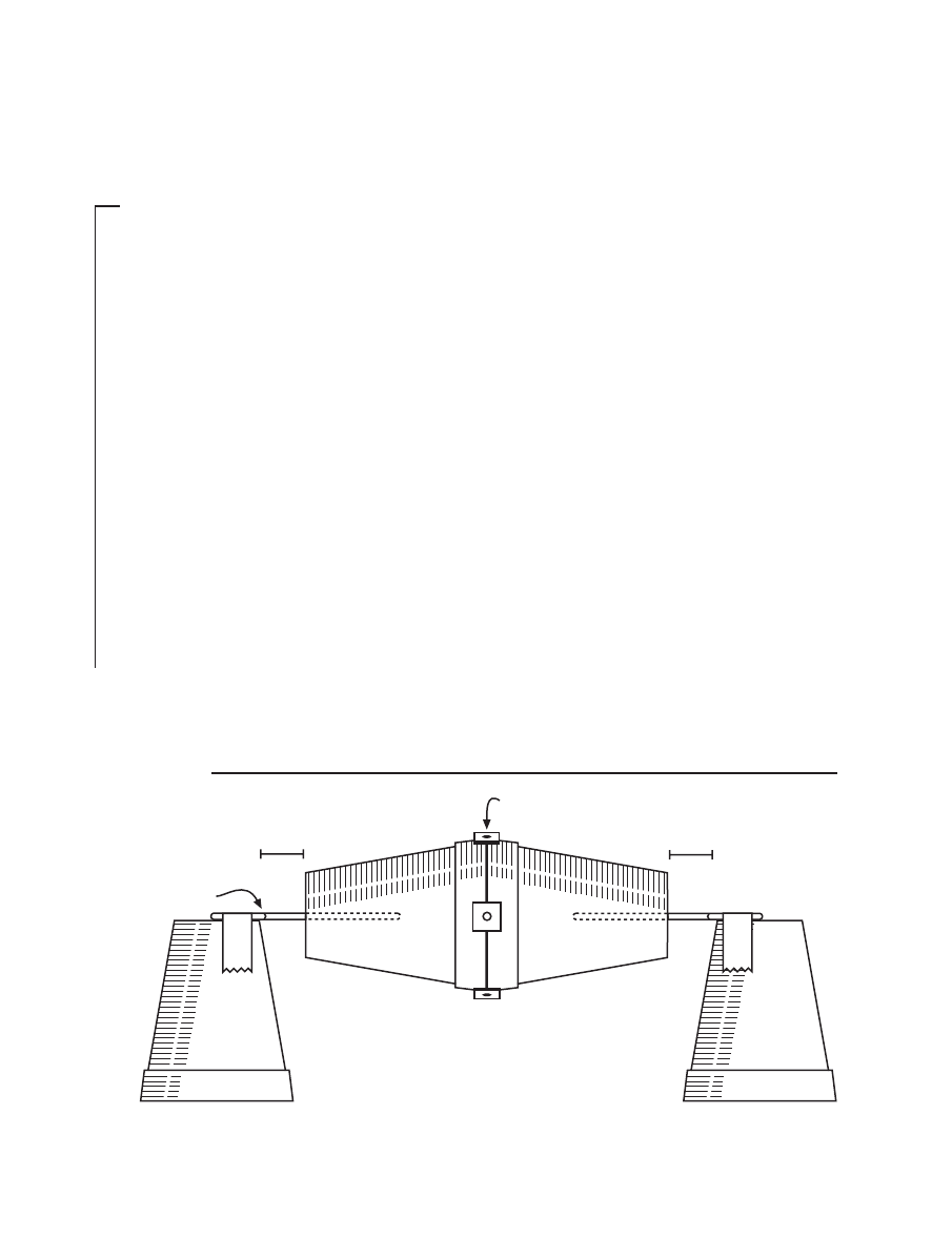
1
Set up the rotor as shown below (Figure 3.1). Leave at least a 30 x 30-cm
area of empty tabletop in front of the rotor. Position the cup stands so that
the rotor easily rotates or spins, but does not move sideways by more than
a centimeter. When you have properly placed the rotor and stands, tape the
cup stands to the tabletop.
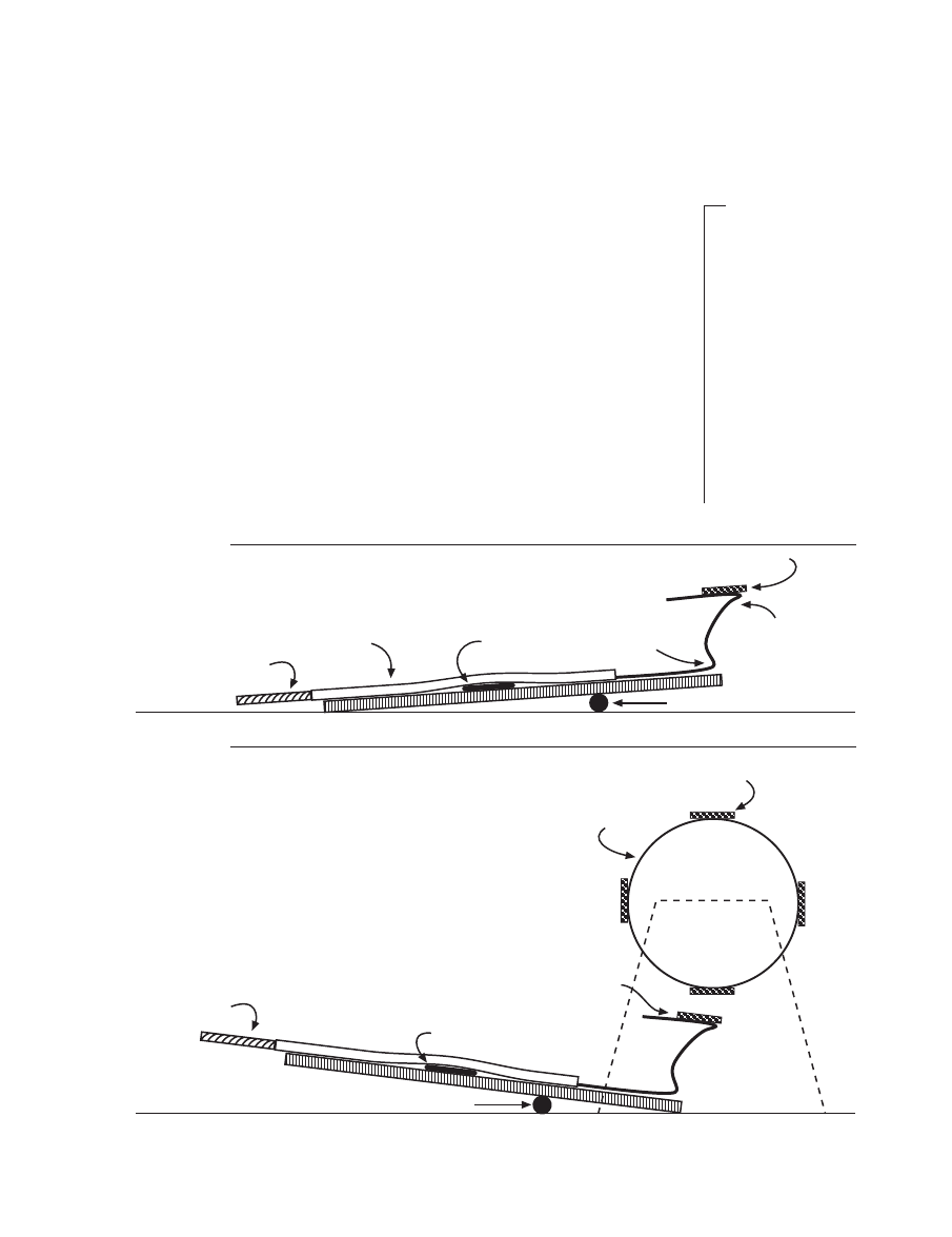
2
Adjust the position of the washer on the flopper so the flopper tips up
slightly on the magnet end (Figure 3.2).
End of small loop
of paper clip
Rotor
magnet
0.5 cm
0.5 cm
F i g u re 3 . 1
29
CHARGING AHEAD: AN INTRODUCTION TO ELECTROMAGNETISM
Flopper straw
Small loop
of paper clip
Large loop
of paper clip
Adjuster straw
Washer
Flopper magnet
Fulcrum
M a t e r i a l s
… c o n t ’ d .
For Part 2—
the electric motor
■ one electromagnet
on its cup stand
■ all the above
materials except one
15 cm wire and the
bulb and its socket
■ additional materials
as listed in the
Teacher’s Guide,
pages 38–39
F i g u re 3 . 2
3
Rotate the rotor and hold it so one of its magnets is as close to the
table as possible (directly under the middle of the rotor). Slide the mag-
net end of the flopper under the rotor so the magnet of the flopper is
directly under the lowest rotor magnet. The rotor magnet and the flopper
magnet should repel one another and the magnet end of the flopper should
tip down. The objective is to get the magnet end of the flopper to tip
down when a rotor magnet is at the lowest point and to tip up after a
rotor magnet moves by the lowest point. It may be necessary to bend the
paper clip holding the flopper magnet in order to move the flopper mag-
net closer to the rotor magnet. After making adjustments, tape both sides
of the fulcrum to the table. Make a final test by rotating the rotor. The
magnet end of the flopper should move down when a rotor magnet comes
close to it and then should move back up after a rotor magnet goes by
(Figure 3.3).
Rotor magnet
Adjuster straw
Washer
Flopper magnet
repelled downward
Rotor
Fulcrum
F i g u re 3 . 3
NATIONAL SCIENCE TEACHERS ASSOCIATION
30
Adjuster straw
(twist to raise or lower
center penny)
Wire
Penny switch
Wire
Center penny string
taped to adjuster straw
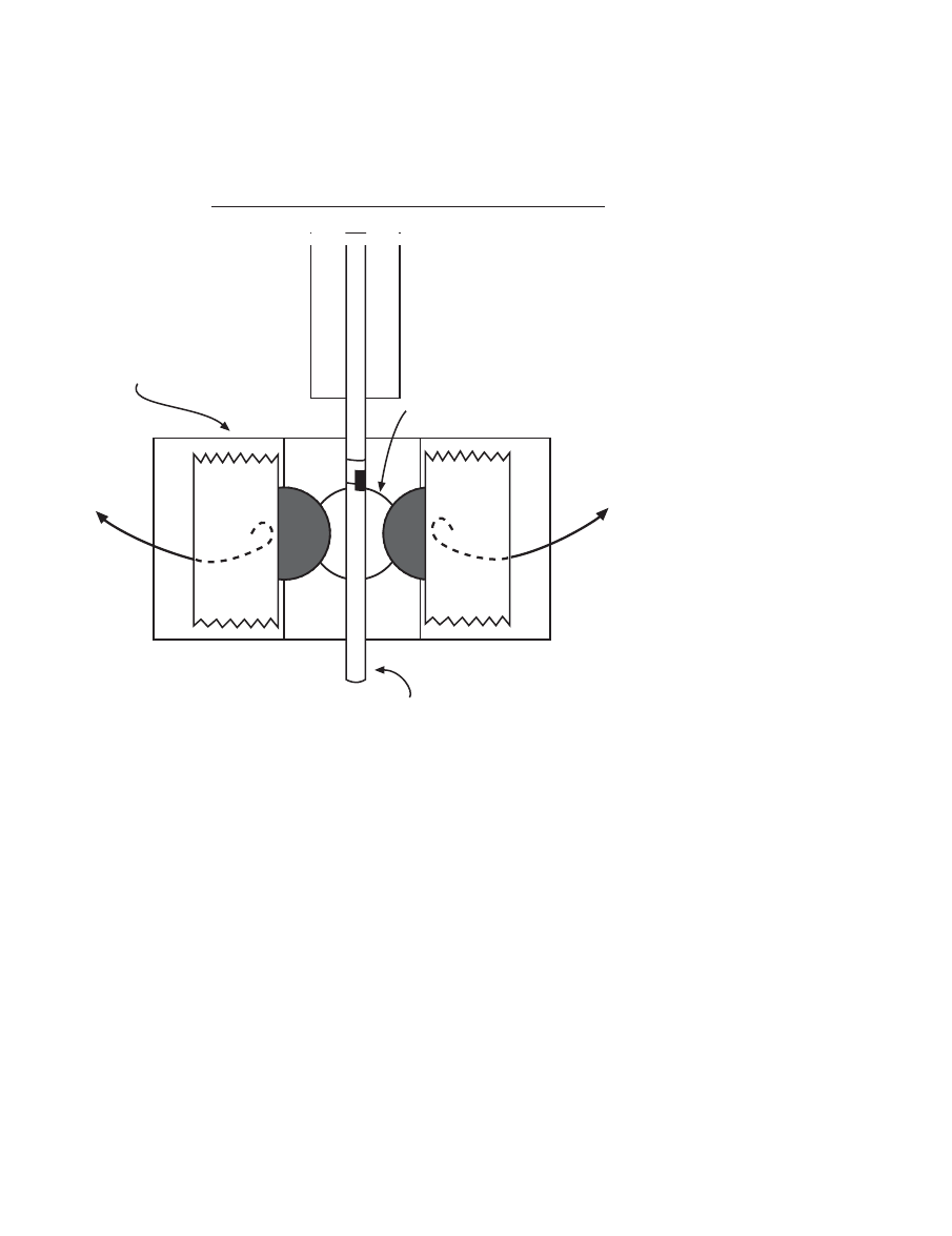
4
Move the penny switch
under the back portion of the
flopper as shown in Figure
3.4. One edge of the adjuster
straw should be midway be-
tween the side pennies of the
penny switch. Make sure the
shiny side of the middle
penny is facing up. Use a
very small piece of tape to
tape the string of the middle
penny to the middle of the
adjuster straw. Make sure
there is at least 3–4 cm of
string between the middle
penny and the straw. Twist
the adjuster straw to shorten
or lengthen the penny string.
When everything is in place,
tape both sides of the penny
switch to the table.
5
Challenge: Your set-up
should look something like
Figure 3.5. Create a circuit
so that the light bulb blinks
on and off as the rotor is
turned. Do not remove the wires from the penny switch. Try not to move the flopper. Use the
adjuster straw to raise and lower the middle penny of the penny switch. Draw “wires” on Figure
3.5 to show how you connected the various parts to create the “strobe” light.
6
When the rotor magnet is directly over the flopper magnet, what does the flopper magnet do?
What does the switch end of the flopper do? Write your answers here.
F i g u re 3 . 4
31
CHARGING AHEAD: AN INTRODUCTION TO ELECTROMAGNETISM
F i g u re 3 . 5
7
When a rotor magnet is directly over the flopper magnet, what hap-
pens to the middle penny of the penny switch? Write your answers here.
+
-
-
+
Rotor
Washer
Flopper
Penny switch

NATIONAL SCIENCE TEACHERS ASSOCIATION
32
8
When a rotor magnet is directly over the flopper magnet, is the penny
switch on (conducting electricity through it) or is the penny switch off?
9
When there is no rotor magnet directly over the flopper magnet, de-
scribe what happens to the flopper magnet and describe what happens to
the switch end of the flopper.
1 0
When no rotor magnet is directly over the flopper magnet, describe
what the flopper is doing to the middle penny of the penny switch.
1 1
When no rotor magnet is directly over the flopper magnet, is the penny
switch on (conducting electricity through it) or is the penny switch off?
P a rt 2 — B u i l d i n g a n E l e c t r i c M o t o r
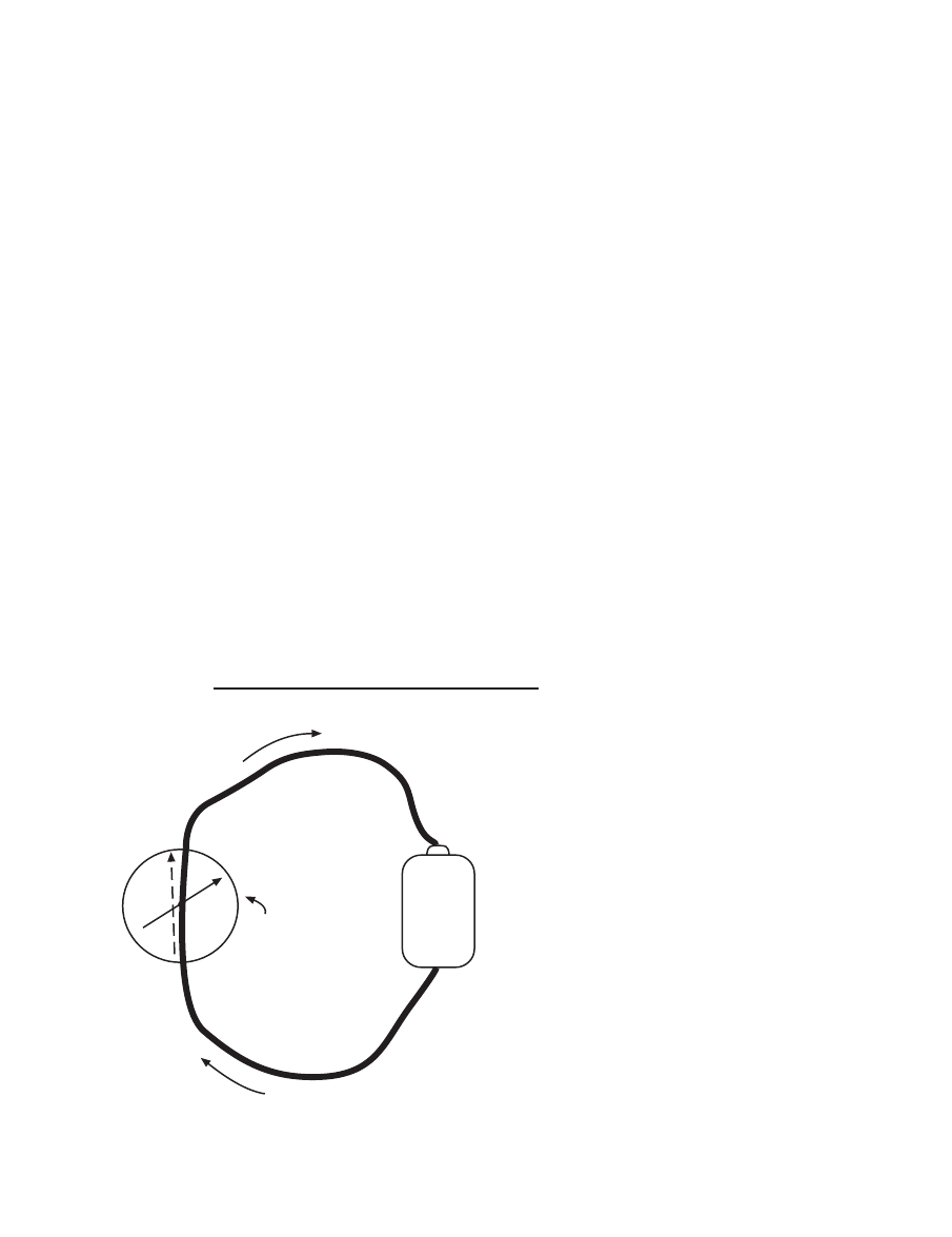
1 2
Put away the bulb and its socket. Place the electromagnet so that it
is as close as possible to the rotor magnets but does not touch any of the
rotor magnets as they pass by (Figure 3.6). Thoroughly tape the electromag-
net cup to the table. Any movement of the cup and electromagnet will re-
duce the operation of the motor.
33
CHARGING AHEAD: AN INTRODUCTION TO ELECTROMAGNETISM
Wire coil
Rotor
Electromagnet
0.5 to 1.0 cm
3.0 to 5.0 cm
60 cm
60 cm
F i g u re 3 . 6
S o m e n o t e s a n d h i n t s :
■
The electromagnet should repel the rotor magnets. If this
does not occur, change the direction of the current
through the electromagnet by turning the batteries
around or by switching the electromagnet wires in the
circuit.
■
Adjust the position of the washer on the flopper. You
might try to get the motor to work without the washer.
■
Try spinning the rotor in different directions. One direc-
tion may work better than the other direction.
■
Try spinning the rotor slowly or giving the rotor a gentle,
but fast spin.
■
Twist the adjuster straw to raise and lower the middle
penny of the penny switch.
■
All electrical contacts must be good. You may have to
use sandpaper to clean the contact points. Make sure the
enamel has been removed from the ends of all wires.
■
Make sure your batteries are fresh. Do not leave a closed
circuit on for very long. A closed circuit through an elec-
tromagnet will quickly wear out the batteries.
1 3
Challenge
:
Arrange the batteries
and wires so that when
the rotor is gently spun,
the rotor keeps spinning
due to the interaction of
the rotor magnets and
the electromagnet. Ar-
range your set-up so
that the electromagnet
repels each of the rotor
magnets. Draw “wires”
on Figure 3.7 to show
how you connected the
objects to get the motor
to work.
1 4
Consider what is happen-
ing when a rotor magnet is di-
rectly over the flopper magnet.
When this occurs, another rotor
magnet is very close to (almost
directly in front of) the electro-
magnet. The penny switch should
be on and electricity should be
flowing through the electromag-
net. Recall that the current-carry-
ing electromagnet and the rotor
magnets have the same poles fac-
ing each other. In this position,
describe below what the electro-
magnet is doing to the rotor mag-
net near it.
NATIONAL SCIENCE TEACHERS ASSOCIATION
34
F i g u re 3 . 7
+
-
-
+
Electromagnet
Rotor
Washer
Flopper
Penny switch

35
CHARGING AHEAD: AN INTRODUCTION TO ELECTROMAGNETISM
1 5
Now consider what is happening when there is no rotor magnet
directly over the flopper magnet. In this case, the electromagnet is in-
between two rotor magnets. One rotor magnet is moving away from the
electromagnet and one is moving toward the electromagnet. Now the penny
switch should be off and no electricity should be going through the electro-
magnet. Explain below why it is a good idea to have the electromagnet
turned off as a rotor magnet moves toward the electromagnet.
H o w R e a l E l e c t r i c M o t o r s Wo r k
Small electric motors, like the motor made in this activity, turn because
of the magnetic interaction between electromagnets and permanent mag-
nets. Usually there are a number of coils or electromagnets in the motor. To
maximize turning, these electromagnets must turn on at precise moments.
In larger motors there are no permanent magnets. The motors operate
due to the magnetic interaction between electromagnets. Again, timing is
everything. The electromagnets must turn on or change their polarity at
precise moments to maximize the turning.
Small motors use a number of electromagnets rather than just one. In
addition, real motors use a commutator and brushes, instead of floppers
and penny switches, to turn the electromagnets on and off. The commuta-
tor rotates with the coils. The brushes remain stationary and conduct elec-
tricity from the power supply to the commutator. The commutator then
conducts the electricity to just one of the coils at a time. The commutator is
insulated so electricity is not conducted from coil to coil.
In Figure 3.8, notice that coil A is receiving electricity from the brushes
through the commutator. Coil B is not in contact with the brushes and is
not receiving electricity. With current flowing through coil A, a magnetic
field is created around coil A. This magnetic field interacts with the mag-
netic field of the permanent magnets and rotates all the coils and the com-
mutator. As the coils and commutator rotate, the brushes lose contact
(through the commutator) with coil A and make contact with coil B. Coil B
then turns on and coil A turns off. The drawing shows just one loop in each
coil. Real coils have many loops wrapped around iron cores and can create
very strong magnetic fields.
NATIONAL SCIENCE TEACHERS ASSOCIATION
36
To power
To power
Brush
Brush
Insulator
Commutator
Coil A
Coil B
Permanent
magnet
Permanent
magnet
F i g u re 3 . 8

37
CHARGING AHEAD: AN INTRODUCTION TO ELECTROMAGNETISM
W h a t i s h a p p e n i n g ?
In this activity, students build an
electric motor from common objects.
In doing so, they see how the mag-
netic interaction between a perma-
nent magnet and electromagnet pro-
duces the rotation of the rotor (see
Figure 3.19). They also see how a
flopper and penny switch maintain
rotation of the rotor by turning the
electromagnet on and off at the right
moments.
The direction of the current
through the electromagnet is chosen
so the electromagnet repels the per-
manent magnets on the rotor. The
repelling force turns the rotor. The
electromagnet turns off as a perma-
nent magnet rotates toward it. This
allows the permanent magnet to ap-
proach the electromagnet without
being repelled by the electromagnet.
T e a c h e r ’ s G u i d e T o
A c t i v i t y 3
Making an
Electric Motor—
Electromagnetism in Action
Then, just as a permanent magnet
moves in front of the electromagnet,
the electromagnet turns on and re-
pels the permanent magnet to push
it around. The flopper and penny
switch work to turn the electromag-
net on and off at the appropriate
times. Students will have to trouble-
shoot and make various changes to
get the motor to work. Trial and er-
ror, persistence, and creative prob-
lem solving will lead to success!
Once students understand the motor
in this activity, they are better pre-
pared to understand the presentation
of how real motors work. The expe-
rience is not unlike what scientists
and engineers go through as they cre-
ate or improve devices. It takes much
effort, testing, and sound thinking to
produce a device that works reliably.
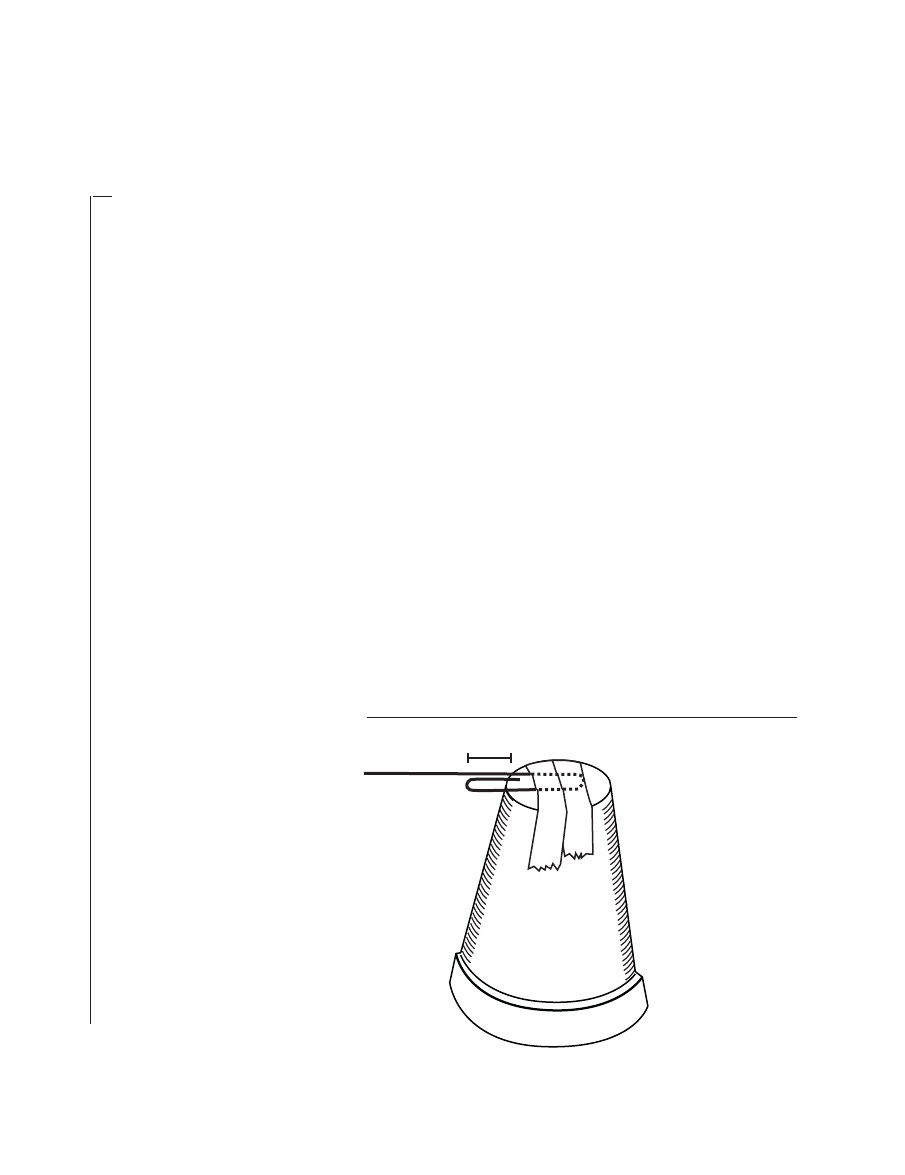
NATIONAL SCIENCE TEACHERS ASSOCIATION
38
T i m e m a n a g e m e n t
At least two class periods of 40–
60 minutes will be required to com-
plete this activity and discuss the re-
sults.
P re p a r a t i o n
The first time this activity is
used, significant preparation is re-
quired. However, since the batteries
are the only consumable items, you
can save your motors for use with
future classes.
There should be one motor for
each group of three to four students
(eight to ten motors per class of
students). Before constructing all of
the materials for class use, you
should build a working model for
yourself so you are familiar with
the construction and operation of
the motor.
There are a number of different
approaches to constructing the parts
of the motor. You can (a) construct all
the parts yourself; (b) enlist a few
careful students to help you with the
construction; or (c) guide groups of
students in the step-by-step construc-
tion of most of the parts.
M a k i n g t h e R o t o r a n d
R o t o r S t a n d s
a
To make stands for the rotor, open
and straighten the large loops of
two large paper clips. Tape these
clips to the bottoms of two cups
(Figure 3.9). Make sure there is
about 1 cm of the small loop that
extends beyond the bottom of the
cup. The end of the small loop
will prevent the rotor from rub-
bing against the stand.
b
Glue two cups together to make
the rotor that will rotate on the
M a t e r i a l s
For the
construction of one
motor:
■ five 1-inch-long
ceramic, rectangular
magnets (available
from Radio Shack
®
Cat. # 64-1879); not
always in stock—
purchase well in
advance
■ five 16-oz plastic
drinking cups
■ three new pennies
■ three plastic drinking
straws
■ one 5-m piece of #24
enamel-coated
magnet wire (with
sanded ends)
■ two 60-cm pieces of
#24 enamel-coated
magnet wire (with
sanded ends)
■ two 15-cm pieces of
wire with stripped
ends
■ one large, iron nail
(approximately 8–10
cm long)
■ four 1.5-volt dry cells
(“C” or “D” size)
■ two battery holders
■ three large paper
clips (giant or jumbo
clips measuring
about 1 cm x 4.8 cm)
Rotor
support
cup
1.0 cm
F i g u re 3 . 9
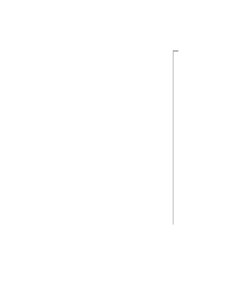
39
CHARGING AHEAD: AN INTRODUCTION TO ELECTROMAGNETISM
■ masking tape
■ one 4 cm x 8.5 cm-
piece of cardboard
from one tablet-back
■ one 18 cm x 2.5 cm-
and two 3 cm x 4 cm-
pieces of corrugated
cardboard
■ one 4 cm x 6 cm-
piece of medium or
fine grit sandpaper
■ one tube of silicon
glue
■ one light bulb (#48 or
1.5–3 volt) in its
socket
■ vinegar and salt (to
clean the pennies)
■ one 3 cm x 0.2 cm-
iron washer
■ one 20-cm piece of
sewing thread
■ utility knife
■ scissors
■ stapler
■ pliers
■ heat source
paper clips of the stands. Melt a
small hole into the bottom of each
of these rotor cups. Open up one
loop of a large paper clip. Use
pliers to hold the end of the pa-
per clip in a flame. Use the hot
end of the paper clip to melt a
small hole in the bottom of each
cup. The hole should be centered,
small, and smooth so the rotor
rotates freely and evenly.
c
To indicate where to place the
permanent magnets on the rotor,
draw a square with sides equal
to the diameter of the cup. Draw
diagonal lines from corner to cor-
ner in the square. Place the cup
upside down inside the square
and mark the rim where the lines
cross the rim.
d
Use silicon glue to glue the rim
of the marked rotor cup to the rim
of the other rotor cup. Make sure
you can see the marks when the
two cups are glued together.
e
After the glue on the rotor cups
is dry, tape (or glue) the four rec-
tangular magnets to the rims of
the cups at the marked positions.
Make sure that the same pole
(north or south) faces outward on
all four magnets. In other words,
the outward facing side of each
magnet should repel the outward
facing side of all the other mag-
nets. Make sure that your last
piece of tape is along the rims, not
across the rims. This reduces the
chance of a snag when you move
the electromagnet close to the ro-
tor magnets.
M a k i n g t h e E l e c t ro m a g n e t
About 60 cm from one end of the
5-m length of #24 magnet wire, start
wrapping most of the wire around
the 3-cm section of nail near the head
of the nail. Do not wrap the last 60
cm of wire. Twist the two 60-cm
lengths of wire together to keep them
from unraveling from the coil. Tape
the nail to the bottom of a cup. Sand
the enamel off the last 3 cm of each
wire. When the electromagnet is
used, you will have to tape the cup
with the electromagnet securely to
the tabletop so that the head of the
nail is about 1 cm from a magnet on
the rotor.
M a k i n g t h e P e n n y S w i t c h
The penny switch consists of
three pennies. Two of the pennies are
separated from each other and are
attached to wires in the circuit. In
between these two side pennies is the
third, middle penny. When this
middle penny is lifted and touches
the two side pennies, the switch is
closed and a current can pass along
the chain of pennies.
a
The pennies must be clean and
shiny. To clean and shine the pen-
nies, put the pennies in a con-
tainer and add enough vinegar to
cover them. Rub salt over the
pennies in this vinegar bath. The
objective is to remove nearly all
of the tarnish from the pennies.
Sand both sides of all the pennies.
b
Use masking tape to attach the
middle of a 20-cm piece of thread
M a t e r i a l s
… c o n t ’ d .
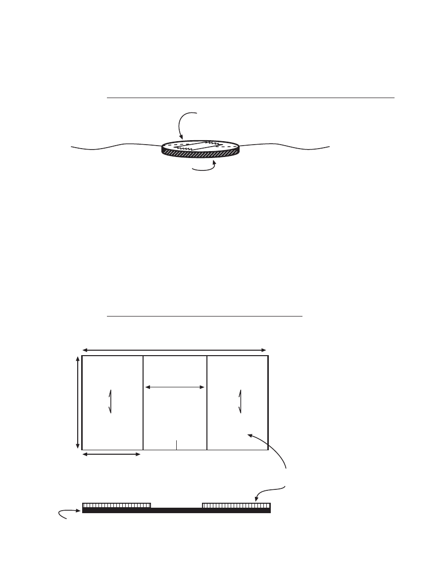
NATIONAL SCIENCE TEACHERS ASSOCIATION
40
to one side of the middle penny
(Figure 3.10). Trim off any excess
tape.
c
Staple the two 3 cm x 4 cm-pieces
of corrugated cardboard to the 4
cm x 8.5-cm piece of tablet-back
cardboard as shown below (Fig-
ure 3.11). Make sure there is 2.5
cm of space between the two
small rectangles. Cut a short slit
in the middle of one long side of
the base.
10 cm
10 cm
Penny
Tape holding
thread to penny
F i g u re 3 . 1 0
Corrugated
cardboard
Side view
Top view
Base for penny switch
Slit
4.0 cm
2.5 cm
8.5 cm
3.0 cm
Tablet-back cardboard
F i g u re 3 . 1 1
d
Sand the enamel from the ends of
two 60-cm lengths of #24 magnet
wire. Make sure there is no enamel
left on the last 3 cm of wire.
e
Use masking tape to tape the wires
to the two side pennies and to the
cardboard as shown in Figure
3.12. The side pennies should be
0.5 cm apart. Press the masking
tape tightly to the wires and pen-
nies to ensure solid contact be-
tween the wires and pennies.
f
Insert the middle
penny beneath the
two side pennies.
The middle penny
should have its
shiny side facing up
and its taped side
facing down. Insert
the string into the
slit and adjust the
string until the
middle penny is in
about the position
shown in Figure
3.13. The string in
the slit keeps the
penny in place. The
other end of the
string will be taped
to the adjuster straw
of the flopper (Fig-
ure 3.13).
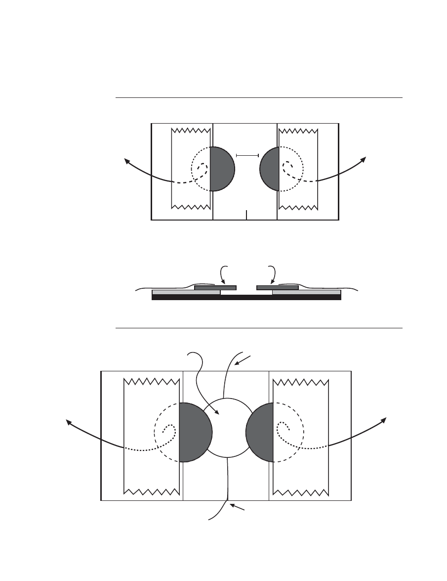
41
CHARGING AHEAD: AN INTRODUCTION TO ELECTROMAGNETISM
Side pennies
60-cm
wire
60-cm
wire
Side view
Top
view
Side pennies and wires taped to penny switch base
60-cm
wire
Slit
60-cm
wire
0.5 cm
F i g u re 3 . 1 2
String to be taped to
adjuster straw of
flopper
Shiny side up;
taped side down
String in slit
F i g u re 3 . 1 3
NATIONAL SCIENCE TEACHERS ASSOCIATION
42
M a k i n g t h e F l o p p e r
a
Tape a 17-cm section of plastic
drinking straw (flopper straw) to
an 18 cm x 2.5-cm piece of corru-
gated cardboard as shown in Fig-
ure 3.14. Start the straw 3 cm from
one end of the cardboard.
b
Cut an 8-cm length of plastic
drinking straw (adjuster straw),
crimp the one end, and insert the
crimped end about 1–2 cm into
the extended end of the flopper
straw. The adjuster straw should
fit snugly inside the flopper
straw, but should be able to turn
inside the flopper straw.
17-cm plastic straw
Adjuster straw goes here
18 cm
3 cm
2.5 cm
F i g u re 3 . 1 4
Side view
Small loop
Top view
Large loop
F i g u re 3 . 1 5
c
Bend open the large
loop of a large paper
clip as shown in Fig-
ure 3.15.
d
Tape the small loop
end of the paper clip
to the end of the
flopper as shown in
Figure 3.16.
e
Insert a rectangular magnet in the
large loop of the paper clip. Make
sure that the side facing upward
repels the magnets on the rotor.
It is important to have the
flopper magnet and each of the
rotor magnets repel one another.
f
Place the washer under the
flopper straw about midway be-
tween the edges of the tape hold-
ing the straw to the cardboard.
Move the 12-cm section of plas-
tic drinking straw (fulcrum) un-
der the flopper until the flopper
just about balances. Tape the ful-
crum to the underside of the
flopper. Move the washer for-
ward or backward along the
flopper to make adjustments.
43
CHARGING AHEAD: AN INTRODUCTION TO ELECTROMAGNETISM
R e m i n d e r s a n d Tro u b l e
S h o o t i n g
When you introduce the activi-
ties, draw students’ attention to the
drawings and materials, and go over
the names of objects (rotor, flopper,
magnet end of the flopper, penny
switch, etc.). This should help them
better understand the challenges and
questions.
It is unlikely that all students will
construct a motor that works per-
fectly. Therefore, you will have to be
prepared to encourage persistence in
troubleshooting and problem solv-
ing. Some potential problems (and
solutions) follow:
■ dry cells may be weak (add more
cells in series)
■ the batteries may not be connected
in series (+ end of one connected
to the – end of the other)
■ the washer may be too far forward
or too far back
■ the adjuster straw may have to be
turned one way or the other to
raise or lower the middle penny of
the penny switch
■ the electromagnet may not be re-
pelling the rotor magnets (change
the direction of current through
the electromagnet)
■ the wires attached to the side pen-
nies of the penny switch may not
be making good contact with the
pennies (disassemble, sand, and
replace)
■ the rotor magnets may not all re-
pel the flopper magnet (flip over
one or more magnets)
■ the electromagnet may be moving
when it interacts with the rotor
magnets (securely tape down the
electromagnet and the support
cup of the electromagnet)
Remind students not to leave
their motors on for very long. Even
if the motor is not running, current
could still be running through the
electromagnet, wearing out the dry
cells.
The same motor may run in dif-
ferent ways. When the washer is on
the flopper, the motor will often run
slowly. Each passing rotor magnet
pushes the flopper down and turns
Adjuster straw
Flopper straw
Flopper
magnet
Small loop of
paper clip
Large loop of
paper clip
F i g u re 3 . 1 6

NATIONAL SCIENCE TEACHERS ASSOCIATION
44
on the electromagnet. When a rotor
magnet moves past the flopper mag-
net, the flopper magnet moves up-
ward and opens the switch at the
other end. When you remove the
washer from the flopper, the motor
often runs relatively fast. In this case,
the flopper is just rapidly jiggling up
and down and is not flopping. The
on-off switching, however, is some-
how still synchronized with the ro-
tor rotation, but how?
In this high-speed case, without
the washer, you would think that the
electromagnet would always be on.
Even when there is no rotor magnet
close to the flopper magnet, the
weight of the flopper magnet (not
counterbalanced by the washer)
should keep the magnet end down
and the switch on. Then, when a ro-
tor magnet passes by, the flopper
magnet should be pushed further
down, keeping the electromagnet on.
Since this is not likely the case, some-
thing else must be occurring.
One possible explanation is that
the flopper magnet might be re-
bounding upward after being
pushed down by a rotor magnet and
held in place by the middle penny
string. This upward rebound of the
flopper magnet might be enough to
tip down the middle penny, break the
circuit in the penny switch, and turn
off the electromagnet.
S u g g e s t i o n s f o r f u rt h e r
s t u d y
You may want to challenge stu-
dents to make changes that make
their motors run faster (or slower).
You may also challenge them to cre-
ate a reliable switch that can replace
the flopper and penny switch. Some
electronics stores have reed switches
for sale. The “reeds” in these switches
are conductors that come together in
the presence of a magnetic field and
close the circuit. A reed switch might
be an effective substitute for the
flopper and penny switch.
Once the motor has operated
successfully, students may want to
see what happens when there are
changes in the number of coils in the
electromagnet, the number of batter-
ies in series, the distance between the
electromagnet and rotor magnets,
and the position of the rotor magnets.
Some students may want to
place both the electromagnet and the
bulb in the circuit so the motor runs
and the light blinks. However, the
resistance of the bulb usually re-
duces the current in the circuit to the
point where the strength of the elec-
tromagnet is not great enough to run
the motor.
Students may want to find some
real motors that no longer work, care-
fully open them, and observe the
commutator, coils, and brushes. Cau-
tion students not to attach power
sources to these dismantled motors.
Serious injury may occur.
Students may also want to build
a very simple electric motor (Figure
3.17):
a
Tape a “D” battery to the bottom
of a cup.
b
Place the magnet, with poles on
the large faces, on the side of the
battery.
45
CHARGING AHEAD: AN INTRODUCTION TO ELECTROMAGNETISM
c
Bend two large paper clips as
shown in Figure 3.17. Hold the pa-
per clips to the battery with a rub-
ber band or with masking tape.
d
Wrap a meter of 24-gauge
enamel-coated magnet wire
around a toilet paper tube to cre-
ate the coil. Make sure there is
enough wire at the ends to wrap
around the coil to hold the coil
together and to extend out from
the coil about 5 cm.
e
Sand the enamel off the 5-cm
ends of the coil.
f
Bend and move the end coil wires
so they are in line with the axis
of the coil.
g
Place the coil in the paper clip
cradle and gently spin the coil.
h
Bend the paper clips and move
the magnet to adjust the relative
position of the coil and magnet.
i
Press the paper clips to the ter-
minals of the battery.
j
With some trial and error adjust-
ments, the coil should begin spin-
ning. The coil spins as its mag-
netic field interacts with the
magnet field of the permanent
magnet. The momentum of the
coil carries the coil through those
regions where the magnetic inter-
action resists the motion of the
coil.
k
Since a short circuit is created, the
coil and cradle wires could get
hot. Remove the coil from the
Battery
Magnet
Coil
Sand enamel off
ends of coil
F i g u re 3 . 1 7
cradle if the coil and wires start
heating up.
Answers
to questions found within the
Student Worksheet on pages 30–35.
5. Draw “wires” on Figure 3.5 to show
how you connected the various parts
to create the “strobe” light.
The correct connections for the
“strobe” light are shown in Fig-
ure 3.18.
6. When the rotor magnet is directly
over the flopper magnet, what does
the flopper magnet do? What does
the switch end of the flopper do?
NATIONAL SCIENCE TEACHERS ASSOCIATION
46
+
-
-
+
Rotor
Washer
Flopper
Penny switch
F i g u re 3 . 1 8
When a rotor magnet is directly
over the flopper magnet, the
flopper magnet moves down-
ward and the switch end of the
flopper moves upward.
7. When a rotor magnet is directly over
the flopper magnet, what happens to
the middle penny of the penny
switch?
When a rotor magnet is directly
over the flopper magnet, the
switch end of the flopper pulls
the middle penny upward.
8. When a rotor magnet is directly over
the flopper magnet, is the penny
switch on (conducting electricity
through it) or is the penny switch off?
When the switch end of the
flopper pulls the middle penny
upward, the middle penny

47
CHARGING AHEAD: AN INTRODUCTION TO ELECTROMAGNETISM
touches the two side pennies,
closes the penny switch, and al-
lows electricity to flow through
the switch. The penny switch
is on.
9. When there is no rotor magnet di-
rectly over the flopper magnet, de-
scribe the movement of the flopper
magnet and describe the movement
of the switch end of the flopper.
When no rotor magnet is directly
over the flopper magnet, the
flopper magnet moves upward
while the switch end of the
flopper moves downward.
10. When no rotor magnet is directly
over the flopper magnet, describe
what the flopper is doing to the
middle penny of the penny switch.
When no rotor magnet is directly
over the flopper magnet, the
switch end of the flopper moves
downward and allows the
middle penny to move down-
ward away from the side pennies.
11. When no rotor magnet is directly over
the flopper magnet, is the penny
switch on (conducting electricity
through it) or is the penny switch off?
When the switch end of the
flopper moves downward and
allows the middle penny to move
downward away from the side
pennies, the middle penny breaks
contact with the side pennies and
opens the penny switch so no
electricity flows through it. The
penny switch is off.
13. Draw “wires” on Figure 3.7 to show
how you connected the objects to get
the motor to work.
The correct connections for the
motor are shown in Figure 3.19.
14. When a rotor magnet is directly over
the flopper magnet, another rotor
magnet is almost directly in front of
the electromagnet. With the penny
switch on and electricity flowing
through the electromagnet, describe
what the electromagnet is doing to
the rotor magnet near it.
With the penny switch on, elec-
tricity should be moving through
the electromagnet and the elec-
tromagnet should be magne-
tized. Since the electromagnet
and the rotor magnet are ar-
ranged to repel one another, the
electromagnet should be repel-
ling the rotor magnet that is di-
rectly in front of it. The repelling
force rotates the rotor.
15. In a case where the electromagnet is
in-between two rotor magnets, one
rotor magnet is moving away from
the electromagnet and one is mov-
ing toward the electromagnet. Ex-
plain why it is a good idea to have
the electromagnet turned off as a ro-
tor magnet moves toward the elec-
tromagnet.
Knowing that the electromagnet
(when on) and rotor magnets re-
pel one another, it is a good idea
to turn off the electromagnet so
that an approaching rotor mag-
net is not repelled by the electro-
magnet.
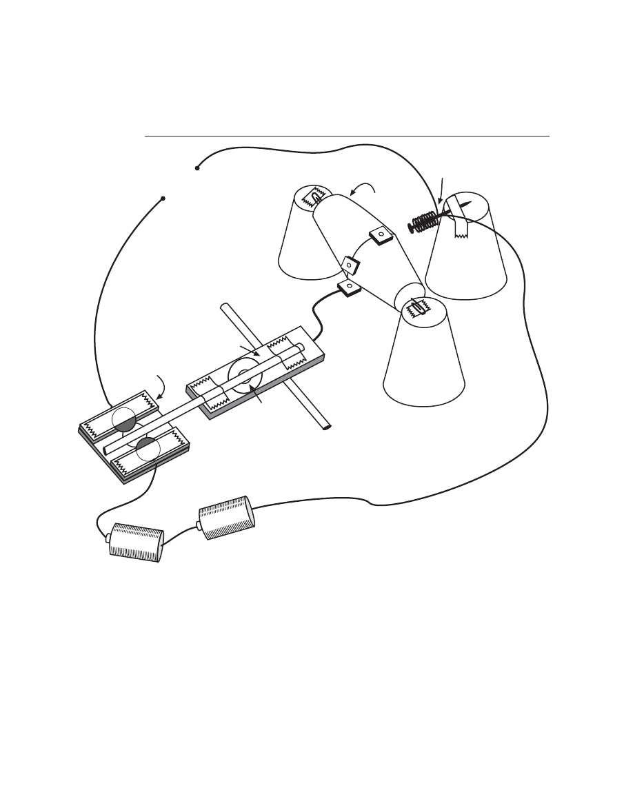
NATIONAL SCIENCE TEACHERS ASSOCIATION
48
+
-
-
+
Electromagnet
Touch wires
to start motor
Rotor
Washer
Flopper
Penny switch
F i g u re 3 . 1 9
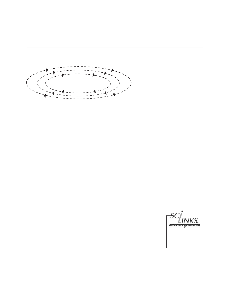
49
CHARGING AHEAD: AN INTRODUCTION TO ELECTROMAGNETISM
A c t i v i t y 4
S t u d e n t W o r k s h e e t
Motion,
Magnetism, and
the Production of Electricity
Topic: generators
Go To:
Code: CH009
B a c k g ro u n d
When Hans Christian Oersted discovered that a current-carrying con-
ductor produces magnetism, the opposite process surely came into ques-
tion: Can magnetism produce electricity? Oersted and others tried to pro-
duce electricity from magnetism, but it wasn’t until 1832—twelve years after
Oersted’s discovery—that Michael Faraday, an English physicist, and Jo-
seph Henry, an American physicist, independently and simultaneously pro-
duced electricity from magnetism. Faraday gets the credit because he was
first to publish his discovery. What Oersted and others missed, but what
Faraday and Henry discovered, was that in order to produce electricity from
magnetism, it is necessary to move the magnet or the wire. In this activity,
you will observe how motion and magnetism can produce electricity and in
the process you will be building a generator.
C o n c e p t G o a l s
■
A generator can be built from available simple materials (magnets, wire,
etc.).
■
If a closed circuit coil is moved in a magnetic field, an electrical current is
produced in the coil and circuit.
■
Motion and magnetism create the electricity that we use in our homes,
schools, and businesses.
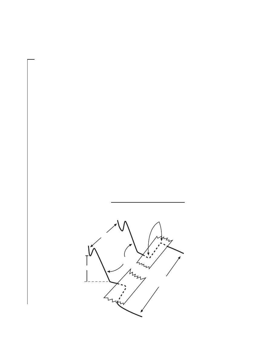
NATIONAL SCIENCE TEACHERS ASSOCIATION
50
M a t e r i a l s
For each group:
■ one 3-m piece of 24-
gauge enamel-
coated wire (for the
rotating coil)
■ two 40-cm pieces of
24-gauge enamel-
coated wire (sand the
enamel from 4-cm
sections at the end of
the wires)
■ two pieces of 20-
gauge copper wire,
each about 20 cm
long
■ two strong ceramic or
rubberized magnets
with the poles on the
larger surfaces or
faces. The magnets
can be circular or
rectangular and
should measure
about 1.6 cm to 2.5
cm across and about
0.3 cm thick.
■ masking tape
■ wire cutters
■ one 7-cm x 11.5-cm
piece of medium or
fine grit sandpaper
(used to sand the
enamel from the
ends of the wires)
■ a felt-tipped marker to
wrap the coil around
(optional)
■
Stronger magnets, more loops in the coil, and a faster spinning coil pro-
duce more current.
■
Some power plants use fossil fuel or nuclear energy to form steam that
turns coils to produce electricity. Other power plants use wind and mov-
ing water (streams and rivers) to turn coils to produce electricity.
P ro c e d u re
1
As noted in the Background section above, electricity can be produced
in wires from magnetism and either movement of the wire or movement of
the magnet (WIRES + MAGNETISM + MOVEMENT = ELECTRICITY IN
THE WIRES). Movement of magnets might cause movement in the needles
of the current detectors. Therefore, to make sure that the movement in the
needles is caused by electricity and not by moving magnets, it will be better
to keep the magnets still and move the wires.
2
One way to make a lot of wire move rapidly in a small space is to create
a coil of wire and have that coil spin in a cradle. If a coil has not been pro-
vided, make a coil by following the directions at the end of this activity
(“How to Make the Rotating Coil,” pages 58–60).
Cradle
Top view of cradle
3.5 - 4 cm
2.3 cm
Right angle bends
"Tails"
of cradle
F i g u re 4 . 1
3
Making the Cradle
for the Rotating Coil
(Figures 4.1 and 4.2). The
cradle consists of two
copper wires (each 20 cm
long) that hold the rotat-
ing coil and allow it to
spin. At least 5-cm sec-
tions of the ends of these
wires must be bare cop-
per wire (no plastic insu-
lation or enamel). The
cradle conducts any elec-
tricity generated by the
rotating coil to the cur-
rent detector (galvanom-
eter or coil and compass).
The two pieces of 20-
gauge wire (heavy wire)
are bent into the shapes
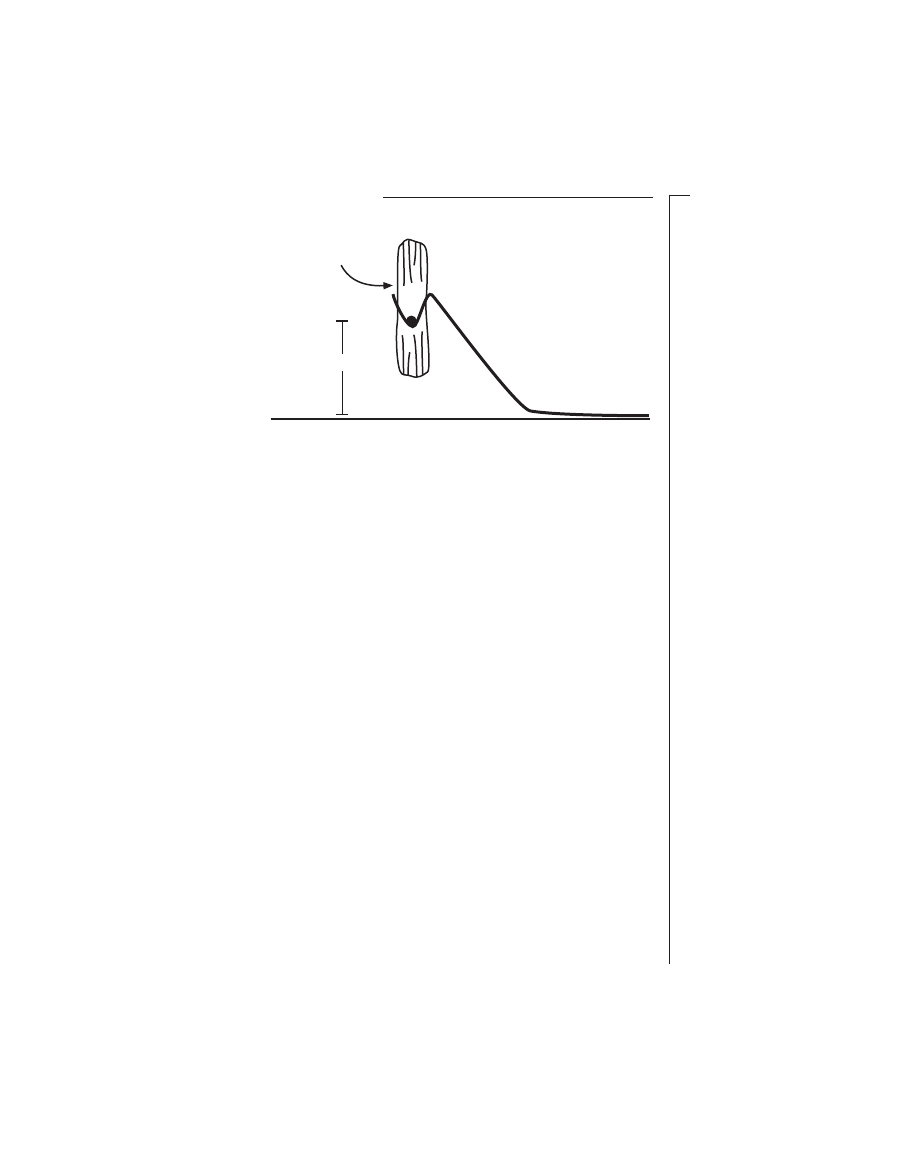
51
CHARGING AHEAD: AN INTRODUCTION TO ELECTROMAGNETISM
M a t e r i a l s
… c o n t ’ d .
■ a current detector
(either a
galvanometer or a
coil and magnetic
compass)
If a galvanometer is
not available, the
following materials
are needed to
make a current
detector from a
coil and magnetic
compass (See
“How to Make a
Current Detector”
on page 60):
■ one directional,
magnetic compass
(the compass must
not “lock up” or
“stick” when the
needle is stationary)
■ one 4.5-m piece of
24-gauge, enamel-
coated wire (for the
compass coil). Sand
the enamel from 4-
cm sections at the
ends of the wire.
■ one square piece of
cardboard (tablet-
back thickness) with
sides that are about
1 cm longer than the
diameter of the
compass body
~2.3 cm
Rotating coil
Side view of cradle
F i g u re 4 . 2
as shown in Figures 4.1 and 4.2 and are taped to the table about 3.5 cm to 4
cm apart. The bottom of the cradle loops should be about 2.3 cm off the
tabletop. Note in the top view that there are right-angle bends in the wire
on the table. The cradle is more secure when the right-angle bends are se-
curely taped to the table.
4
Connecting the Current Detector to the “Tails” of the Cradle.
Use the
two 40-cm pieces of 24-gauge wire to connect the “tail” of the cradle to the
current detector (see Figure 4.3). Make sure that 4-cm sections of the ends of
the wires have been sanded to remove the enamel. Also, it might help to
sand the “tails” of the cradle as well. Move the current detector at least 20
cm away from the rotating coil and cradle.
If a compass and coil are used as a current detector, rotate the compass
and coil on the tabletop until the compass needle lines up with the top of
the coil. Since any movement of the compass and coil will make it hard to
detect needle movement, tape the compass support to the table. Also, tape
down wires leading to the compass and coil.
5
Giving the Coil a Spin.
Once the cradle has been connected to the cur-
rent detector, place the rotating coil in the cradle. Using one of the “tails” of
the rotating coil, give the coil a spin. Movement of the needle of the current
detector indicates that electricity was produced in the rotating coil. Was
there any evidence that the electricity was produced in the rotating coil?
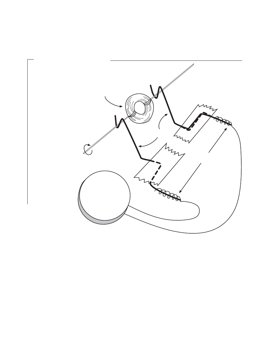
NATIONAL SCIENCE TEACHERS ASSOCIATION
52
M a t e r i a l s
… c o n t ’ d .
Optional Materials
for Making a Magnet
Holder (See “How to
Make a Magnet
Holder” on page 61):
■ one rectangular piece
of cardboard (tablet-
back thickness),
approximately 1 cm x
8 cm
■ one giant or jumbo
paper clip
(approximately
4.8 cm x 1 cm)
■ one 4-cm section of
plastic drinking straw
■ one “D” battery or
beaker. Since the
battery is used only
to hold a magnet, the
battery can be dead.
6
Challenge: Figure out how to use one or both magnets with the rotat-
ing coil to produce and detect electricity. Recall that sandwich magnets have
poles on the large, flat surfaces (not on the ends). Also, recall that like poles
repel and different poles attract. The position of the poles will likely be
important in meeting this challenge. One person may want to hold the mag-
nets while another person spins the rotating coil. A third person may want
to watch the current detector. Whenever a test is made, make sure that the
magnets are not moving.
Cradle
Rotating coil
Current detector
(Galvanometer or
compass and coil)
40 cm
40 cm
"Tails"
of cradle
F i g u re 4 . 3

53
CHARGING AHEAD: AN INTRODUCTION TO ELECTROMAGNETISM
Describe how you hold the magnets around the rotating coil to produce
and detect electricity. The poles are important. Try to discover and describe
how the poles should be placed.
7
Once electricity is produced and detected, answer the following ques-
tions through experimentation:
a
Try spinning the coil in different directions. How is the direction of coil
spin related to the direction in which the needle moves?
b
Compare needle deflection for slow spinning and fast spinning. How
does the rate of spin relate to the extent of needle deflection and conse-
quently to the electrical current in the wire?

NATIONAL SCIENCE TEACHERS ASSOCIATION
54
c
What do you think would happen to the deflection and current if just
1 m of wire, rather than 3 m, was used to make the rotating coil?
d
What do you think would happen to the deflection and the current if
weaker magnets were used?
8
Faraday’s Law. Michael Faraday and Joseph Henry independently dis-
covered that a current could be produced in a closed circuit coil if that coil
moved relative to a magnetic field or region of magnetic influence. The coil
must move and/or the magnetic field must move such that the coil wires
move across the magnetic field, which runs from north pole to south pole.
The production of electricity from motion and magnetism is called electro-
magnetic induction.
Faraday was first to get his discovery published so he gets most of the
credit for discovering electromagnetic induction. Faraday also had a law
named after him, “Faraday’s Law of Induction.” In terms of this activity,
Faraday’s law would predict that if the number of loops in the coil is doubled
and if the coil spins twice as fast (cuts the magnetic field twice as often), the
induced current would be four times as great (assuming the same resis-
tance).
9
The Production of Electricity for the Community. The electricity that
is made available to your home and community is produced in a way that is
very similar to the way electricity was produced in this activity. In your

55
CHARGING AHEAD: AN INTRODUCTION TO ELECTROMAGNETISM
community or in a community
nearby there is an electrical power
plant. In that plant, coils of wire are
moved in a magnetic field. As a con-
sequence, an electrical current is pro-
duced in the coils and in the wires
leading to your home where the elec-
tricity is used to run your electrical
devices.
In this activity, chemical energy
in you was transformed into energy
of motion (spinning the coil), which
was transformed into electrical and
magnetic energy (current in the
wires), which was transformed back
into energy of motion (movement of
current detector needle). In electrical
power plants, motion energy (spin-
ning of coils) is transformed into elec-
trical and magnetic energy.
Power plants have different ways
of moving the coils. For some (hydro-
electric plants) running or falling wa-
ter from rivers is used to turn the coils.
For others, coal or gas (fossil fuel) is
burned to produce steam, which turns
the coils. For still others, nuclear en-
ergy is used to produce steam, which
turns the coils. In some cases (wind-
mills), wind is used to turn the coils.
It can be said that we get most of our
electrical energy from moving air or
water (liquid or gas).
How fascinating it is to think that
energy from some cold stream miles
away is transmitted almost instantly
to the warm computer on which this
sentence is being typed and stored…
and to think that others are dipping
into that same stream for the energy
used to run their computers, lights,
and innumerable gadgets.
Less than two and a half life-
times ago we did not know how to
produce electricity from magnetism.
Thanks to Faraday and Henry, not
only do we now know how to do
that, but we have built on that foun-
dation to create a wondrous collec-
tion of electrical systems and devices.
Communication around the world
used to take months or years. Now,
even without connecting wires, we
can communicate with minimum
delay in words and pictures with
nearly anyone in the world. The dis-
covery of electromagnetism and elec-
tromagnetic induction has shrunk the
human world and stands as one of
the most significant advances of the
20th century.
NATIONAL SCIENCE TEACHERS ASSOCIATION
56
Topic: conductors
Go To:
Code: CH010
T E C H N O L O G I C A L T I E - I N
S u p e rc o n d u c t o r s
Scientists and engineers are working on improving the way we gen-
erate and distribute electricity. Wires in the coils of generators and wires
between the power plant and our homes, schools, and businesses all re-
sist the flow of electricity. If we could reduce that resistance so the elec-
tricity could move more easily, then we would be able to use less energy
to produce electricity and we would be able to reduce pollution that comes
from the production of electricity. Scientists and engineers are working
on ways of reducing electrical resistance. They have already discovered
that some materials at very low temperatures provide no resistance to the
flow of electricity. These materials are called superconductors. If we had
highways that acted like superconductors, we could get our car up to 60
miles per hour, shut off the engine, and coast at 60 miles per hour for as
long as we wanted to. We would not have to use fuel to move down the
highway; therefore we would save money and energy and have a cleaner
environment. The problem at this point in time is that superconductors
have to be kept super cold. Keeping things cold (about 200 Celsius de-
grees below the freezing point of water) requires the use of energy. Scien-
tists and engineers are currently trying to create superconducting materi-
als that operate at relatively high temperatures. Creating a superconductor
that operated at room temperature would revolutionize the electrical
world. Scientists and engineers are experimenting with superconducting
power lines and with superconducting electrical generators. If the super-
conducting generators and power lines prove successful, we will prob-
ably be able to cut our costs, energy requirements, and pollution to more
than half of what they are today.
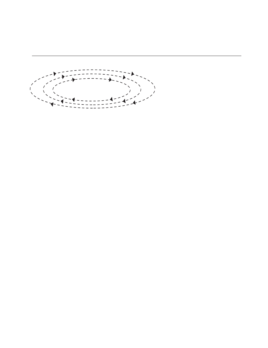
57
CHARGING AHEAD: AN INTRODUCTION TO ELECTROMAGNETISM
T e a c h e r ’ s G u i d e T o
A c t i v i t y 4
Motion,
Magnetism, and
the Production of Electricity
W h a t i s h a p p e n i n g ?
In this activity, students learn
how to produce or generate electric-
ity from moving a closed circuit (coil)
through a magnetic field. They con-
struct a coil that spins in a cradle.
Magnets held close to the spinning
coil create a magnetic field (region of
magnetic influence) in which the coil
spins. The wires of the coil cut across
the magnetic field between the two
magnets and a current is created in
the spinning coil, in the cradle, and
in the current detector.
Students observe that the direc-
tion in which the coil is spun deter-
mines the direction in which the
needle of the current detector is de-
flected and hence the direction the
current is moving. They also learn
that when the coil is spun faster, there
is greater needle deflection, which
indicates greater current. In addition,
students learn that stronger magnets
and more loops in the spinning coil
would produce greater current (de-
flection).
The simple generator made in
this activity is related to the genera-
tors used by electrical power plants.
Basically students learn that power
plants move coils in magnetic fields
and in the process produce the elec-
tricity used in homes and the com-
munity. Energy is required to move
the coils, whether the coils are on
classroom desktops or in power
plants. Students learn that fossil fu-
els and nuclear energy are used to
form steam, which turns the power
plant coils. Students also learn that
wind and moving water (from rivers
and dams) are used to turn the coils
in the production of household elec-
tricity.

NATIONAL SCIENCE TEACHERS ASSOCIATION
58
T i m e m a n a g e m e n t
Two class periods of 40–60 min-
utes each should be enough time to
complete the activity and discuss the
results. If galvanometers are avail-
able, then less time is required since
students need not make the current
detector from a compass and coil.
Also, more time can be saved by hav-
ing a couple of careful students help
after school to make all the rotating
coils for the class. Once these coils are
made they can be used repeatedly by
other classes.
P re p a r a t i o n
To save classroom time, use stu-
dent help to cut all of the materials
prior to class (e.g., wires, sections of
drinking straws, and the cardboard
for the compass and the magnet
holders).
If a compass is being used to de-
tect currents, that compass should be
in good working order. Very small
currents and their associated mag-
netic fields will not deflect a compass
needle if that needle tends to stick
when it is stationary. Check to see
that smoothly operating compasses
are used in this activity. If a needle
does seem to stick, have the student
lightly tap the compass to set the
needle jiggling. With the needle jig-
gling, spin the rotating coil and look
for evidence of deflection and cur-
rent.
Also, if compasses are being
used to detect currents, warn stu-
dents to keep magnets and iron ob-
jects away from their compasses. A
compass needle will be held in place
by a nearby iron object or magnet and
therefore might not be easily de-
flected by the weak magnetic field
from the coil around the compass.
H o w t o M a k e t h e R o t a t i n g
C o i l
1
About 15 cm from one end of the
3-m wire, start wrapping the wire
around an index finger or a felt-
tipped marker. Keep the wire
rather snug around the object, but
loose enough to get the coil off the
object. Leave about 15 cm of un-
wrapped wire at the end of the
wire. Wrap the two 15-cm ends
about three times around the coil
on opposite sides of the coil. Cut
the wires so about 5 cm of wire
extend outward on each side of
the coil. These wires are the “tails”
of the rotating coil (see Figure 4.4).
2
Sand only the tops of the 5-cm
“tails” (wires) of the rotating coil.
To do this, place a piece of card-
board at the edge of the table (see
Figure 4.5). Hold the coil in a ver-
tical position on the edge of a
table with one “tail” resting on
the cardboard. Sand the top of the
“tail.” Also, sand the top of the
other “tail.” Make sure the same
sides of the wires are sanded.
Also, make sure the tops of the
wires are sanded near the coil. Do
not sand the wire that is in the
coil.
3
Straighten and bend the “tails” so
they line up through the middle
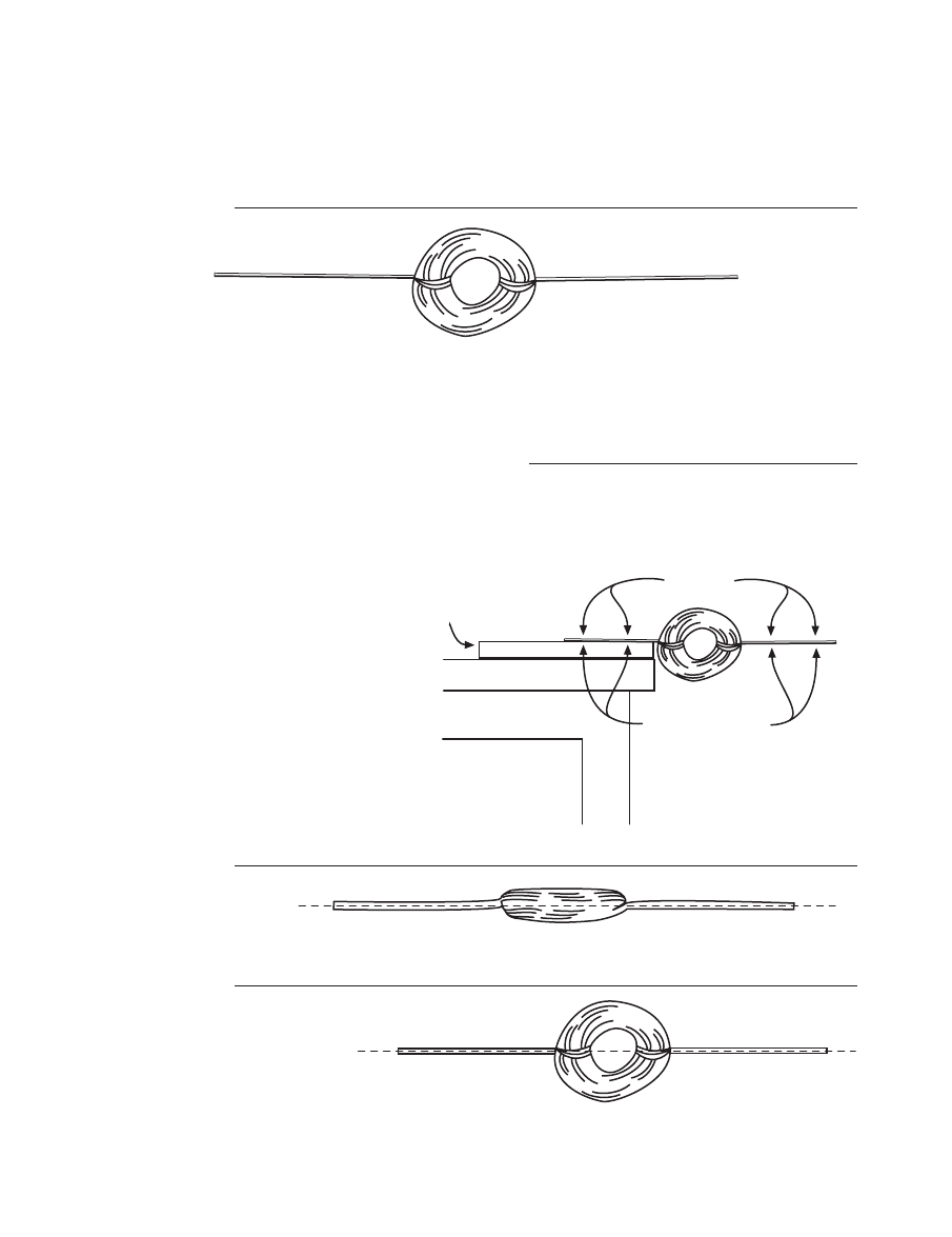
59
CHARGING AHEAD: AN INTRODUCTION TO ELECTROMAGNETISM
Rotating coil made from wrapping
3 mm of wire around a felt-tipped marker or index finger
5 cm
5 cm
F i g u re 4 . 4
Side view
Cardboard to
protect table
Table
Sand top
of wires
Leave enamel on
bottoms of wires
F i g u re 4 . 5
F i g u re 4 . 6
F i g u re 4 . 7
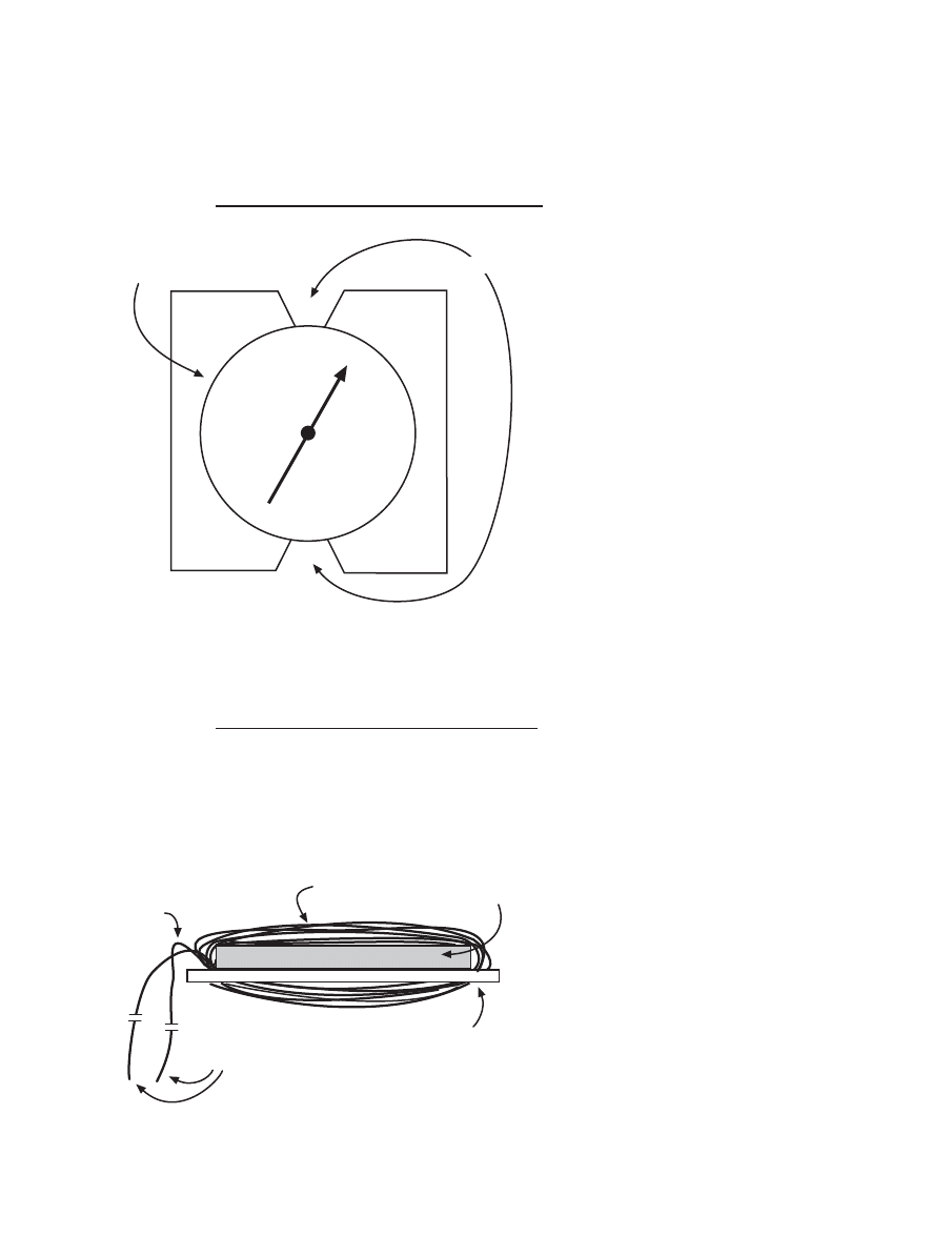
NATIONAL SCIENCE TEACHERS ASSOCIATION
60
Side view
Compass
Sand ends
Coil
Cardboard
Twist
F i g u re 4 . 9
Top view
Compass
Wrap wire here
F i g u re 4 . 8
of the coil. Make sure the wires
line up from two different views
(see Figures 4.6 and 4.7). You will
want to bend the wires so the coil
is well balanced and does not
wobble when it spins in the
cradle.
H o w t o M a k e a C u r re n t
D e t e c t o r
1
Cut a square piece of cardboard
with sides about 1 cm longer than
the outside diameter of the com-
pass. Cut 0.5-cm notches in the
middle of two opposite sides of
the square. The notches will hold
the coil of wire over the middle
of the compass.
2
Place the center of the compass
over the center of the square.
Starting about 12 cm from one
end of the 4.5-m piece of wire,
wrap the wire around the com-
pass and square and through the
notches. Stop wrapping when
there is about 12 cm of wire left.
Twist the two wires together
close to the compass. Sand the
enamel off 4-cm sections at the
ends of the wires. (See top view
in Figure 4.8 and side view in Fig-
ure 4.9.)
If the electrical current flowing
through the coil is great enough,
the current will produce mag-
netism strong enough to move
the compass needle.
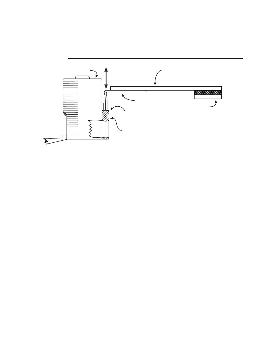
61
CHARGING AHEAD: AN INTRODUCTION TO ELECTROMAGNETISM
H o w t o M a k e a
M a g n e t H o l d e r
A magnet holder can be used to
hold a magnet over the rotating coil
(Figure 4.10).
1
Tape a magnet to the end of the 1
cm x 8 cm-piece of cardboard.
2
Tape a 4-cm section of plastic
drinking straw to a battery (dead
or alive) or beaker.
3
Bend the large loop of a jumbo
paper clip so that the large loop
is a right angle to the rest of the
paper clip.
4
Tape the large loop of the paper
clip to the piece of cardboard as
shown.
5
Slip the small loop of the paper
clip into the straw.
6
Slide the cardboard, clip, and
magnet up and down in the straw
to adjust the height of the magnet.
1 cm x 8 cm cardboard
Magnet
Large loop of paper clip
Small loop of paper clip
inside straw
Slide up and down
to adjust magnet
Battery
4-cm section of straw
F i g u re 4 . 1 0
7
Set the magnet over the top of the
rotating coil.
Question:
If this magnet is directly
over the rotating coil, where should
the other magnet be placed to pro-
duce the greatest current in the coil?
S u g g e s t i o n s f o r f u rt h e r
s t u d y
Students may be challenged to
see how changes in the rotating coil
might produce more or less current
(deflections). Will a rotating coil
made from 1 m of wire produce the
same deflection (current) as a rotat-
ing coil made from 3 m of wire? Does
the gauge of the wire make a differ-
ence? What will happen if weaker or
stronger magnets are used?
Students may wonder why only
half the enamel is removed from both
ends of the rotating coil wire. If the
enamel is removed from all around
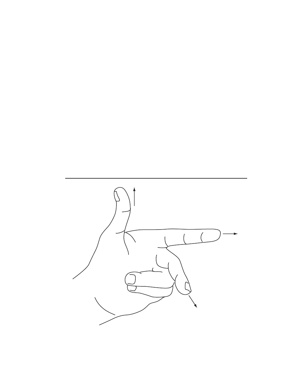
NATIONAL SCIENCE TEACHERS ASSOCIATION
62
the wire, the coil should produce an
alternating current. An alternating
current is a current that changes di-
rections back and forth in the conduc-
tor. For half a turn of the coil the elec-
tricity would travel in one direction
and for the other half of a turn the
electricity would travel in the oppo-
site direction. Alternating current in
the compass coil would produce an
alternating magnetic field and the
needle would jiggle back and forth
after an initial jump in one direction.
To produce an intermittent, di-
rect current, and hence sustained
needle deflection in one direction, the
enamel is left on half the wire so that
no electricity flows to the compass
coil during that half of the turn.
How can we tell which way the
current should be traveling in a con-
ductor that is moving across a mag-
netic field? A left-hand rule for gen-
erators or electromagnetic induction
can be used. To implement the rule,
point the thumb and index finger of
the left hand perpendicular to one
another. Point the thumb in the di-
rection the conductor is moving and
point the index finger in the direction
of the magnetic field (from north pole
to south pole). The middle finger,
held perpendicular to both the
thumb and index finger, will point in
the direction of the electron flow (see
Figure 4.11).
Direction
conductor
is moving
Direction of
magnetic field
(north to south pole)
Direction of
electron flow
F i g u re 4 . 1 1
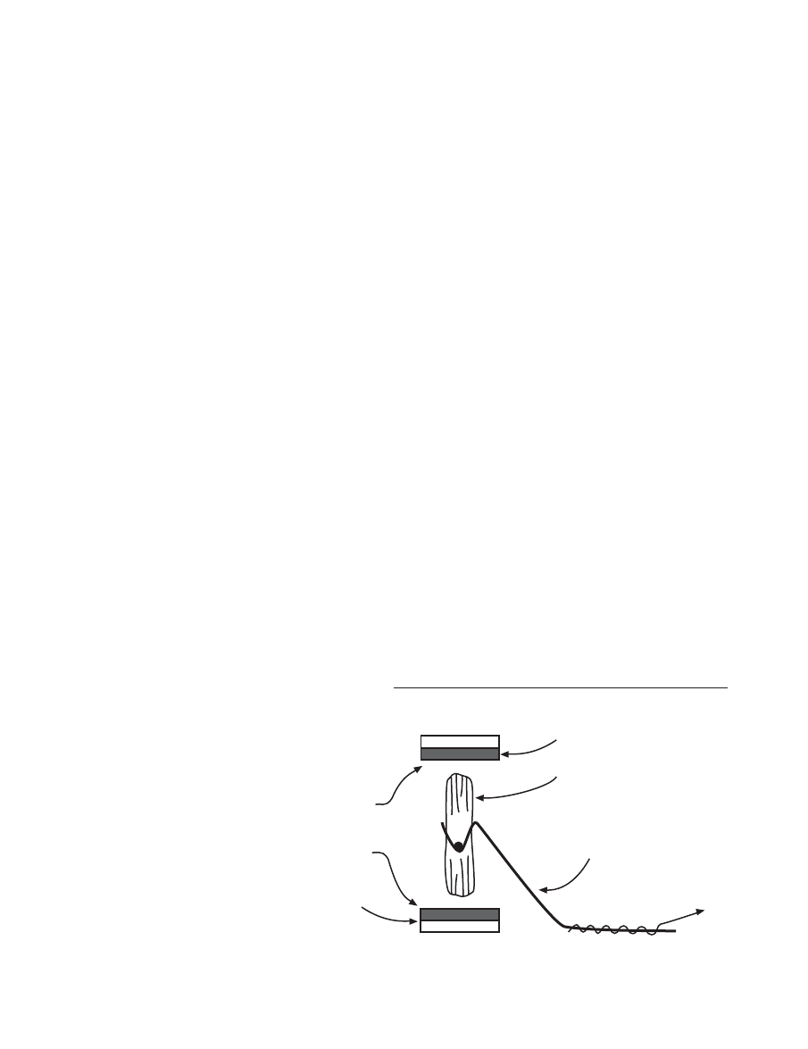
63
CHARGING AHEAD: AN INTRODUCTION TO ELECTROMAGNETISM
Interested students may be chal-
lenged to use this left-hand rule to
determine the direction of electron
flow in a coil that is rotating in a
magnetic field. It may help to sim-
plify the rotating coil by considering
only one or two loops. Students
should discover that the current
moves in one direction during one
half of a spin and moves in the op-
posite direction during the other half
of the spin.
Answers
to questions found within
Procedure on pages 51–54.
5. Was there any evidence that the elec-
tricity was produced in the rotating
coil?
Here the students spin the coil in
the cradle, but without using the
magnets. If magnets are not held
close to the spinning coil, no elec-
tricity will be produced in the coil
and no current will be detected.
6. Describe how you hold the magnets
Side view of cradle
Cradle
Note: Magnet
poles on
opposite sides
of coils are
different
Rotating coil
Magnet
To current
detector
Magnet
N N N N N
S S S S S
N N N N N
S S S S S
F i g u re 4 . 1 2
■
Place one magnet directly un-
der the rotating coil. Where
would you place the other
magnet to produce electricity
in the spinning coil?
■
Hold the other side (pole) of
the magnet close to the spin-
ning coil.
■
The magnets need to be on op-
posite sides of the spinning
coil.
■
The pole (or side of the mag-
net) facing the coil might make
a difference.
The magnet arrangement that
will produce the strongest cur-
rent will be one in which magnets
are held on opposite sides of the
coil, with different poles facing
each other (see Figure 4.12). For
example, if one magnet is placed
close to and directly under the
coil and the other magnet is held
close to and directly over the top
around the rotating coil
to produce and detect
electricity.
Students meet this
challenge by holding
the two magnets mo-
tionless in various
places about the spin-
ning coil. The chal-
lenge can be difficult.
Here are a couple of
hints to give students
if frustration levels
run too high.

NATIONAL SCIENCE TEACHERS ASSOCIATION
64
of the coil and if the magnets’
poles closest to the coil are dif-
ferent (magnets attracting), then
electricity should be generated in
the spinning coil.
7a. How is the direction of coil spin re-
lated to the direction in which the
needle moves?
When the direction of coil spin is
reversed, the needle deflection
and current are reversed as well.
7b. How does the rate of spin relate to
the extent of needle deflection and
consequently to the electrical current
in the wire?
Faster spin produces greater
needle deflection and greater cur-
rent.
7c. What would happen to the deflection
and current if just 1 m of wire (rather
than 3 m) were used?
A coil made with 1 m of wire
would produce less needle de-
flection and current than a simi-
lar coil made from 3 m of wire.
7d. What do you think would happen to
the deflection and current if weaker
magnets were used?
Weaker magnets would produce
less needle deflection and current
than stronger magnets.

65
CHARGING AHEAD: AN INTRODUCTION TO ELECTROMAGNETISM
C i rc u i t
A circuit is a path of objects along
which an electrical current can flow.
The circuit usually includes an elec-
trical power source (battery or gen-
erator) and wires that run to and from
the power source.
C l o s e d C i rc u i t
A closed circuit is a circuit that has
an unbroken path of conductors that
run to and from the power source.
There are no non-conducting sections
along a closed circuit path.
C o i l
A coil is made when an insulated
wire is wrapped a number of times
around an object in the same direc-
tion. Usually the wraps of wire lie on
top of or next to the other wraps of
wire. If the object is removed, the
wire wraps are still considered to be
a coil. When an electrical current
passes through the coil, magnetism
is created around each wrap. Since
many wraps are on top of each other
or beside each other, the magnetism
from each wrap adds up to produce
a strong magnetic effect (attraction)
around the coil.
C o n d u c t o r
A conductor is a material that elec-
tricity or an electrical current can eas-
ily pass though. Metals are usually
good conductors of electricity.
C u r re n t
Current is a measure of how “fast”
the electricity is moving in a conduc-
tor. The speed is not measured in
speedometer speed (e.g., 50 miles per
hour). It is measured by counting the
number of charges (electrons or pro-
tons) that pass any point in the con-
ductor in one second. If you sat be-
side a highway and counted the
number of cars that passed you in a
second or minute or hour, you would
be measuring the “current” of cars
(e.g., 35 cars in one hour). The “cur-
rent” of cars would not be the same
as their speed (e.g., 50 miles per
hour).
E l e c t r i c a l R e s i s t a n c e
Some materials allow electricity to
easily flow through them. Other ma-
terials make it difficult for electricity
to flow through them. Electrical re-
sistance is a measure of how hard an
object resists the flow of electricity
through it. Objects with high resis-
tance put up a great resistance to the
flow. Objects with low resistance put
up little resistance to the flow. For
example, the longer and skinnier a
wire is, the more resistance it has to
the flow of electricity.
E l e c t ro m a g n e t i c I n d u c t i o n
When a conductor is in a changing
magnetic field (region of magnetism),
a voltage is produced (induced) in the
conductor and that voltage can pro-
Glossary

NATIONAL SCIENCE TEACHERS ASSOCIATION
66
duce an electrical current in the con-
ductor. This process is called electro-
magnetic induction. The electricity
that we use in our homes, schools, and
businesses is produced by electromag-
netic induction. Generators produce
electricity by electromagnetic induc-
tion. In Activity 4, when the genera-
tor coil spins between two magnets,
the coil moves though different re-
gions of magnetism. This produces an
electrical current in the spinning coil
and this current is detected by the
galvanometer or the stationary coil
and compass.
E l e c t ro m a g n e t i s m
Electromagnetism is the production
of magnetism in the space around a
wire carrying an electrical current.
Also, electromagnetism is the pro-
duction of magnetism in the space
around a moving charged particle.
E l e c t ro n s
Electrons are negatively charged par-
ticles that move around the nucleus
of atoms. Electrons in metals are not
held tightly to the nucleus and can
move in metals. Electrons move in
wires that are part of closed circuits.
G e n e r a t o r
A generator is a device that trans-
forms energy of motion into electri-
cal energy. In a generator, a coil and
magnetic field move relative to each
other. This movement produces or
generates electricity in the coil. The
generated electricity is sent over
power lines to homes, schools, and
businesses.
I n t e r a c t i o n
Interaction occurs when objects do
something to each other. When a bat
strikes a ball, the ball and bat hit each
other and therefore interact. When a
magnet is moved near an iron object,
the magnet and iron object attract
each other and therefore interact.
Magnets, whether permanent mag-
nets or electromagnets, can interact
(attract and repel) with each other.
M a g - l e v Tr a i n s
Mag-lev trains are trains that do not
touch the track as they move along.
The train is both held off the track
(levitated) and propelled down the
track by strong electromagnets. With-
out the friction of wheels rolling
alone a track, the mag-lev trains can
move very fast (over 300 miles per
hour), very smoothly, and with little
pollution. Scientists and engineers
are experimenting with these mag-
netic levitation (mag-lev) trains.
M a g n e t i c F i e l d
The magnetic field is the region or
space around an object where there
is a magnetic effect. A magnetic ef-
fect is the attraction of iron or the at-
traction and repulsion of a magnet.
A magnet, a current-carrying wire,
and a moving charged particle pro-
duce magnetic fields around them.

67
CHARGING AHEAD: AN INTRODUCTION TO ELECTROMAGNETISM
M a g n e t i s m
Magnetism is the property of attract-
ing iron or steel objects.
N o n - c o n d u c t o r
A non-conductor is a material that
electricity or an electrical current
does not easily pass through. Non-
metals are usually good non-conduc-
tors. Another name for “non-conduc-
tor“ is “insulator.” An insulator
keeps electricity from passing from
one object to another object.
O p e n C i rc u i t
An open circuit is a circuit that has a
non-conductor (air or other non-con-
ductors) in the path that runs to and
from the power source.
R o t o r
The rotor is a part of a machine that
rotates or spins around and does
work. The interaction of magnets
makes the rotor spin around in an
electric motor.
S h o rt C i rc u i t
A short circuit is a closed circuit that
presents little resistance to the flow
of electricity. A short circuit is there-
fore an “easy” circuit. A copper or
aluminum wire connecting one end
of a battery to the other end of a bat-
tery produces a short circuit. Short
circuits often heat up wires, which
can cause burns or fires.
S u p e rc o n d u c t o r s
Superconductors are electrical con-
ductors that offer little or no resis-
tance to the flow of electricity. At the
present time, superconductors exist
only at very low temperatures.
V o l t a g e
To get charges to move in conduc-
tors, the charges have to be pushed.
Voltage is a measure of how hard the
charges are pushed. When the volt-
age is high, the charges are given a
big push and carry lots of energy.
When the voltage is low, the charges
are given a small push and carry a
little energy. In a circuit, when the
voltage is increased, the current in-
creases if everything else stays the
same.
Document Outline
- 0873551885
- Contents
- Overview
- A Learning Map on Electricity and Magnetism
- Guide to Relevant National Science Education Content Standards
- Sci Links
- Activity 1: A Bonus from Electrical Flow#8212;Magnetism
- Activity 2 : Coils and Electromagnets
- Activity 3: Making an Electric Motor—Electromagnetism in Action
- Activity 4: Motion, Magnetism, and the Production of Electricity
- Glossary
Wyszukiwarka
Podobne podstrony:
Aspden Synchronous Lattice Electrodynamics as an Alternative to Time Dilation (1987)
Whittaker E T On an Expression of the Electromagnetic Field due to Electrons by means of two Scalar
Zizek, Slavoj Looking Awry An Introduction to Jacques Lacan through Popular Culture
An Introduction to the Kabalah
the, a, an i used to XAHZ4X75E3D62UCGT4P36VSZLEDY6C52CQHHJDQ
An Introduction to USA 6 ?ucation
An Introduction to Database Systems, 8th Edition, C J Date
An Introduction to Extreme Programming
Adler M An Introduction to Complex Analysis for Engineers
An Introduction to American Lit Nieznany (2)
(ebook pdf) Mathematics An Introduction To Cryptography ZHS4DOP7XBQZEANJ6WTOWXZIZT5FZDV5FY6XN5Q
An Introduction to USA 1 The Land and People
An Introduction to USA 4 The?onomy and Welfare
An Introduction to USA 7 American Culture and Arts
An Introduction To Olap In Sql Server 2005
Anon An Answer to the Booke Called O (2)
An Introduction to Yang Mills Theory
An Introduction to Linux Systems?ministration
An introduction to the Analytical Writing Section of the GRE
więcej podobnych podstron