Heat Engines, Entropy, and the
Second Law of Thermodynamics
C H A P T E R O U T L I N E
22.1 Heat Engines and the Second
Law of Thermodynamics
22.2 Heat Pumps and Refrigerators
22.3 Reversible and Irreversible
Processes
22.4 The Carnot Engine
22.5 Gasoline and Diesel Engines
22.6 Entropy
22.7 Entropy Changes in
Irreversible Processes
22.8 Entropy on a Microscopic
Scale
Chapter 22
▲
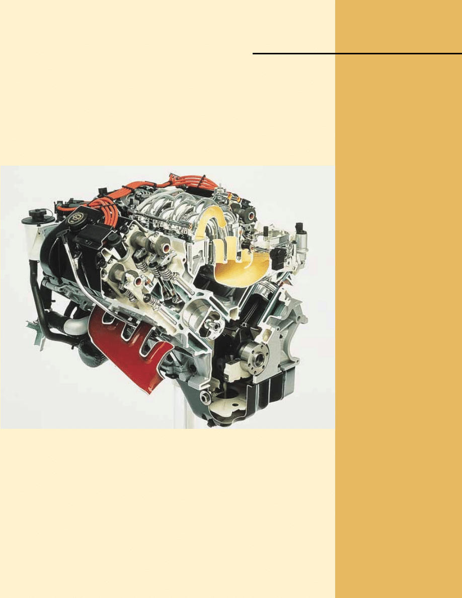
This cutaway image of an automobile engine shows two pistons that have work done on
them by an explosive mixture of air and fuel, ultimately leading to the motion of the
automobile. This apparatus can be modeled as a heat engine, which we study in this chapter.
(Courtesy of Ford Motor Company)
667

668
T
he first law of thermodynamics, which we studied in Chapter 20, is a statement of
conservation of energy. This law states that a change in internal energy in a system can
occur as a result of energy transfer by heat or by work, or by both. As was stated in
Chapter 20, the law makes no distinction between the results of heat and the results of
work—either heat or work can cause a change in internal energy. However, there is an
important distinction between heat and work that is not evident from the first law. One
manifestation of this distinction is that it is impossible to design a device that, operat-
ing in a cyclic fashion, takes in energy by heat and expels an equal amount of energy by
work. A cyclic device that takes in energy by heat and expels a fraction of this energy by
work is possible and is called a heat engine.
Although the first law of thermodynamics is very important, it makes no distinc-
tion between processes that occur spontaneously and those that do not. However,
only certain types of energy-conversion and energy-transfer processes actually take
place in nature. The second law of thermodynamics, the major topic in this chapter,
establishes which processes do and which do not occur. The following are examples
of processes that do not violate the principle of conservation of energy if they pro-
ceed in either direction, but are observed to proceed in only one direction, governed
by the second law:
• When two objects at different temperatures are placed in thermal contact with
each other, the net transfer of energy by heat is always from the warmer object to
the cooler object, never from the cooler to the warmer.
• A rubber ball dropped to the ground bounces several times and eventually comes
to rest, but a ball lying on the ground never gathers internal energy from the
ground and begins bouncing on its own.
• An oscillating pendulum eventually comes to rest because of collisions with air mol-
ecules and friction at the point of suspension. The mechanical energy of the system
is converted to internal energy in the air, the pendulum, and the suspension; the
reverse conversion of energy never occurs.
All these processes are irreversible—that is, they are processes that occur naturally in
one direction only. No irreversible process has ever been observed to run backward—if
it were to do so, it would violate the second law of thermodynamics.
1
From an engineering standpoint, perhaps the most important implication of the
second law is the limited efficiency of heat engines. The second law states that a ma-
chine that operates in a cycle, taking in energy by heat and expelling an equal amount
of energy by work, cannot be constructed.
1
Although we have never observed a process occurring in the time-reversed sense, it is possible for it to
occur. As we shall see later in the chapter, however, the probability of such a process occurring is
infinitesimally small. From this viewpoint, we say that processes occur with a vastly greater probability in
one direction than in the opposite direction.
Lord Kelvin
British physicist and
mathematician (1824–1907)
Born William Thomson in Belfast,
Kelvin was the first to propose
the use of an absolute scale of
temperature. The Kelvin
temperature scale is named in
his honor. Kelvin’s work in
thermodynamics led to the idea
that energy cannot pass
spontaneously from a colder
object to a hotter object.
(J. L. Charmet/SPL/Photo
Researchers, Inc.)
S E C T I O N 2 2 . 1 • Heat Engines and the Second Law of Thermodynamics
669
22.1 Heat Engines and the Second Law
of Thermodynamics
A
heat engine is a device that takes in energy by heat
2
and, operating in a cyclic
process, expels a fraction of that energy by means of work. For instance, in a typical
process by which a power plant produces electricity, coal or some other fuel is burned,
and the high-temperature gases produced are used to convert liquid water to steam.
This steam is directed at the blades of a turbine, setting it into rotation. The mechani-
cal energy associated with this rotation is used to drive an electric generator. Another
device that can be modeled as a heat engine—the internal combustion engine in an
automobile—uses energy from a burning fuel to perform work on pistons that results
in the motion of the automobile.
A heat engine carries some working substance through a cyclic process during
which (1) the working substance absorbs energy by heat from a high-temperature en-
ergy reservoir, (2) work is done by the engine, and (3) energy is expelled by heat to a
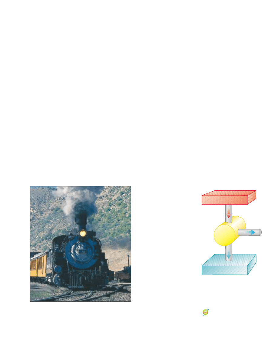
lower-temperature reservoir. As an example, consider the operation of a steam engine
(Fig. 22.1), which uses water as the working substance. The water in a boiler absorbs
energy from burning fuel and evaporates to steam, which then does work by expand-
ing against a piston. After the steam cools and condenses, the liquid water produced
returns to the boiler and the cycle repeats.
It is useful to represent a heat engine schematically as in Figure 22.2. The engine
absorbs a quantity of energy
!Q
h
! from the hot reservoir. For this discussion of heat en-
gines, we will use absolute values to make all energy transfers positive and will indicate
the direction of transfer with an explicit positive or negative sign. The engine does
work W
eng
(so that negative work W ! " W
eng
is done on the engine), and then gives up
a quantity of energy
!Q
c
! to the cold reservoir. Because the working substance goes
2
We will use heat as our model for energy transfer into a heat engine. Other methods of energy
transfer are also possible in the model of a heat engine, however. For example, the Earth’s atmosphere
can be modeled as a heat engine, in which the input energy transfer is by means of electromagnetic
radiation from the Sun. The output of the atmospheric heat engine causes the wind structure in the
atmosphere.
Figure 22.1 This steam-driven
locomotive runs from Durango to
Silverton, Colorado. It obtains its
energy by burning wood or coal.
The generated energy vaporizes
water into steam, which powers the
locomotive. (This locomotive must
take on water from tanks located
along the route to replace steam
lost through the funnel.) Modern
locomotives use diesel fuel instead
of wood or coal. Whether old-
fashioned or modern, such
locomotives can be modeled as
heat engines, which extract energy
from a burning fuel and convert a
fraction of it to mechanical energy.
©
Phil
Degginger/Stone/Getty
Hot reservoir at T
h
Q
h
Q
c
W
eng
Cold reservoir at T
c
Engine
Active Figure 22.2 Schematic
representation of a heat engine.
The engine does work W
eng
. The
arrow at the top represents energy
Q
h
#
0 entering the engine. At the
bottom, Q
c
$
0 represents energy
leaving the engine.
At the Active Figures link
at http://www.pse6.com, you
can select the efficiency of the
engine and observe the
transfer of energy.

through a cycle, its initial and final internal energies are equal, and so %E
int
!
0.
Hence, from the first law of thermodynamics, %E
int
!
Q & W ! Q " W
eng
, and with
no change in internal energy,
the net work W
eng
done by a heat engine is equal
to the net energy Q
net
transferred to it. As we can see from Figure 22.2,
Q
net
!
|Q
h
| " |Q
c
|; therefore,
(22.1)
If the working substance is a gas,
the net work done in a cyclic process is the
area enclosed by the curve representing the process on a PV diagram. This is
shown for an arbitrary cyclic process in Figure 22.3.
The
thermal efficiency e of a heat engine is defined as the ratio of the net work
done by the engine during one cycle to the energy input at the higher temperature
during the cycle:
(22.2)
We can think of the efficiency as the ratio of what you gain (work) to what you give
(energy transfer at the higher temperature). In practice, all heat engines expel only a
fraction of the input energy Q
h
by mechanical work and consequently their efficiency
is always less than 100%. For example, a good automobile engine has an efficiency of
about 20%, and diesel engines have efficiencies ranging from 35% to 40%.
Equation 22.2 shows that a heat engine has 100% efficiency (e ! 1) only if
!Q
c
! ! 0—that is, if no energy is expelled to the cold reservoir. In other words, a heat
engine with perfect efficiency would have to expel all of the input energy by work. On
the basis of the fact that efficiencies of real engines are well below 100%, the
Kelvin–Planck form of the second law of thermodynamics states the following:
It is impossible to construct a heat engine that, operating in a cycle, produces no
effect other than the input of energy by heat from a reservoir and the performance
of an equal amount of work.
This statement of the second law means that, during the operation of a heat engine,
W
eng
can never be equal to
!Q
h
!, or, alternatively, that some energy !Q
c
! must be
rejected to the environment. Figure 22.4 is a schematic diagram of the impossible
“perfect” heat engine.
e !
W
eng
! Q
h
!
!
! Q
h
! " ! Q
c
!
! Q
h
!
!
1 "
! Q
c
!
! Q
h
!
W
eng
!
!Q
h
! " !Q
c
!
670
C H A P T E R 2 2 • Heat Engines, Entropy, and the Second Law of Thermodynamics
P
V
Area = W
eng
Figure 22.3 PV diagram for an
arbitrary cyclic process taking place
in an engine. The value of the net
work done by the engine in one
cycle equals the area enclosed by
the curve.
Thermal efficiency of a heat
engine
Quick Quiz 22.1
The energy input to an engine is 3.00 times greater than
the work it performs. What is its thermal efficiency? (a) 3.00 (b) 1.00 (c) 0.333
(d) impossible to determine
Quick Quiz 22.2
For the engine of Quick Quiz 22.1, what fraction of the en-
ergy input is expelled to the cold reservoir? (a) 0.333 (b) 0.667 (c) 1.00 (d) impossible
to determine
Example 22.1 The Efficiency of an Engine
An engine transfers 2.00 ' 10
3
J of energy from a hot reser-
voir during a cycle and transfers 1.50 ' 10
3
J as exhaust to a
cold reservoir.
(A)
Find the efficiency of the engine.
Solution The efficiency of the engine is given by Equation
22.2 as
0.250, or 25.0%
e ! 1 "
! Q
c
!
! Q
h
!
!
1 "
1.50 ' 10
3
J
2.00 ' 10
3
J
!
The impossible engine
Q
h
Cold reservoir at T
c
Engine
Hot reservoir at T
h
W
eng
Figure 22.4 Schematic diagram of
a heat engine that takes in energy
from a hot reservoir and does an
equivalent amount of work. It is
impossible to construct such a
perfect engine.

S E C T I O N 2 2 . 2 • Heat Pumps and Refrigerators
671
22.2 Heat Pumps and Refrigerators
In a heat engine, the direction of energy transfer is from the hot reservoir to the cold
reservoir, which is the natural direction. The role of the heat engine is to process the
energy from the hot reservoir so as to do useful work. What if we wanted to transfer en-
ergy from the cold reservoir to the hot reservoir? Because this is not the natural direc-
tion of energy transfer, we must put some energy into a device in order to accomplish
this. Devices that perform this task are called
heat pumps or refrigerators. For exam-
ple, we cool homes in summer using heat pumps called air conditioners. The air condi-
tioner transfers energy from the cool room in the home to the warm air outside.
In a refrigerator or heat pump, the engine takes in energy
!Q
c
! from a cold reser-
voir and expels energy
!Q
h
! to a hot reservoir (Fig. 22.5). This can be accomplished
only if work is done on the engine. From the first law, we know that the energy given up
to the hot reservoir must equal the sum of the work done and the energy taken in from
the cold reservoir. Therefore, the refrigerator or heat pump transfers energy from a
colder body (for example, the contents of a kitchen refrigerator or the winter air out-
side a building) to a hotter body (the air in the kitchen or a room in the building). In
practice, it is desirable to carry out this process with a minimum of work. If it could be
accomplished without doing any work, then the refrigerator or heat pump would be
“perfect” (Fig. 22.6). Again, the existence of such a device would be in violation of the
second law of thermodynamics, which in the form of the
Clausius statement
3
states:
(B)
How much work does this engine do in one cycle?
Solution The work done is the difference between the
input and output energies:
!
What If?
Suppose you were asked for the power output of
this engine? Do you have sufficient information to answer
this question?
5.0 ' 10
2
J
W
eng
!
! Q
h
! " ! Q
c
! ! 2.00 ' 10
3
J " 1.50 ' 10
3
J
Answer No, you do not have enough information. The
power of an engine is the rate at which work is done by the
engine. You know how much work is done per cycle but you
have no information about the time interval associated with
one cycle. However, if you were told that the engine oper-
ates at 2 000 rpm (revolutions per minute), you could relate
this rate to the period of rotation T of the mechanism of the
engine. If we assume that there is one thermodynamic cycle
per revolution, then the power is
! !
W
eng
T
!
5.0 ' 10
2
J
"
1
2
000
min
#
"
1 min
60 s
#
!
1.7 ' 10
4
W
3
First expressed by Rudolf Clausius (1822–1888).
Q
h
Q
c
Cold reservoir at T
c
Heat pump
W
Hot reservoir at T
h
Active Figure 22.5 Schematic diagram of a heat pump,
which takes in energy Q
c
#
0 from a cold reservoir and
expels energy Q
h
$
0 to a hot reservoir. Work W is done
on the heat pump. A refrigerator works the same way.
▲
PITFALL PREVENTION
22.1 The First and Second
Laws
Notice the distinction between
the first and second laws of
thermodynamics. If a gas under-
goes a one-time isothermal process
%
E
int
!
Q & W ! 0. Therefore,
the first law allows all energy in-
put by heat to be expelled by
work. In a heat engine, however,
in which a substance undergoes a
cyclic process, only a portion of
the energy input by heat can be
expelled by work according to
the second law.
At the Active Figures link
at http://www.pse6.com, you
can select the COP of the heat
pump and observe the transfer
of energy.
It is impossible to construct a cyclical machine whose sole effect is to transfer energy
continuously by heat from one object to another object at a higher temperature
without the input of energy by work.
In simpler terms,
energy does not transfer spontaneously by heat from a cold
object to a hot object. This direction of energy transfer requires an input of energy to
a heat pump, which is often supplied by means of electricity.
The Clausius and Kelvin–Planck statements of the second law of thermodynamics
appear, at first sight, to be unrelated, but in fact they are equivalent in all respects. Al-
though we do not prove so here, if either statement is false, then so is the other.
4
Heat pumps have long been used for cooling homes and buildings, and they are
now becoming increasingly popular for heating them as well. The heat pump contains
two sets of metal coils that can exchange energy by heat with the surroundings: one set
on the outside of the building, in contact with the air or buried in the ground, and the
other set in the interior of the building. In the heating mode, a circulating fluid flow-
ing through the coils absorbs energy from the outside and releases it to the interior of
the building from the interior coils. The fluid is cold and at low pressure when it is in
the external coils, where it absorbs energy by heat from either the air or the ground.
The resulting warm fluid is then compressed and enters the interior coils as a hot,
high-pressure fluid, where it releases its stored energy to the interior air.
An air conditioner is simply a heat pump with its exterior and interior coils inter-
changed, so that it operates in the cooling mode. Energy is absorbed into the circulat-
ing fluid in the interior coils; then, after the fluid is compressed, energy leaves the
fluid through the external coils. The air conditioner must have a way to release energy
to the outside. Otherwise, the work done on the air conditioner would represent en-
ergy added to the air inside the house, and the temperature would increase. In the
same manner, a refrigerator cannot cool the kitchen if the refrigerator door is left
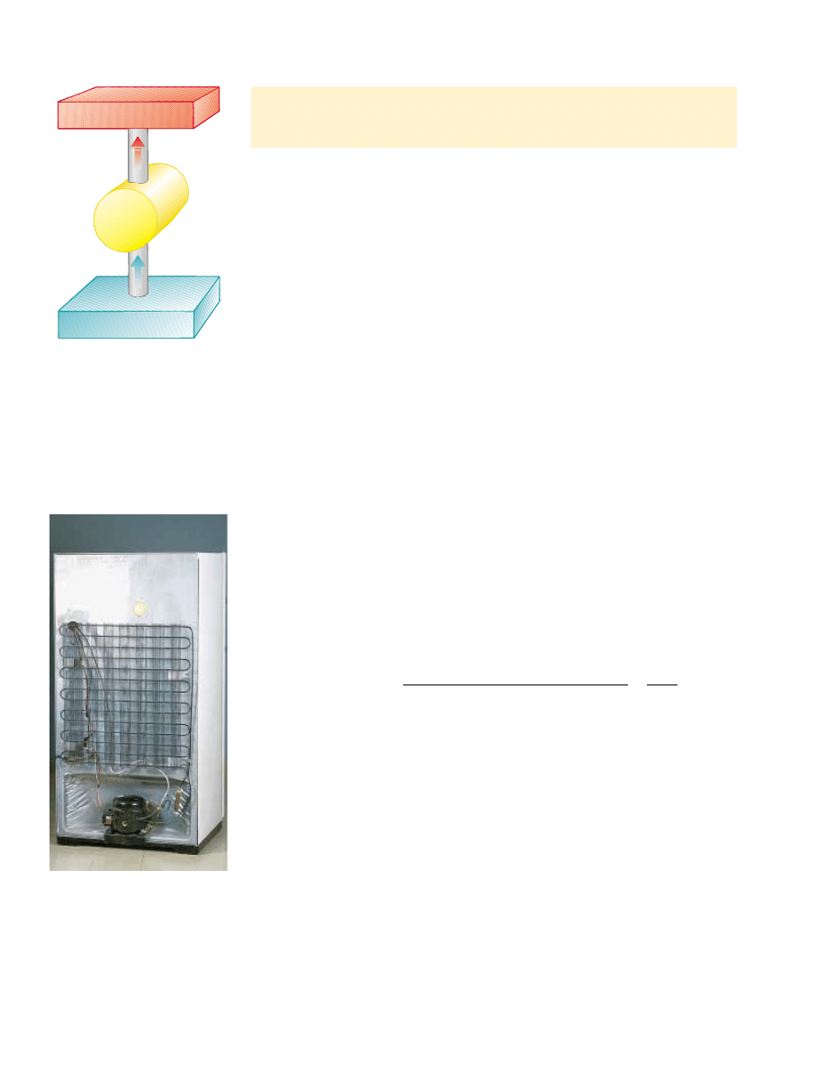
open. The amount of energy leaving the external coils (Fig. 22.7) behind or under-
neath the refrigerator is greater than the amount of energy removed from the food.
The difference between the energy out and the energy in is the work done by the elec-
tricity supplied to the refrigerator.
The effectiveness of a heat pump is described in terms of a number called the
coeffi-
cient of performance (COP). In the heating mode, the COP is defined as the ratio of
the energy transferred to the hot reservoir to the work required to transfer that energy:
(22.3)
Note that the COP is similar to the thermal efficiency for a heat engine in that it is a
ratio of what you gain (energy delivered to the interior of the building) to what you
give (work input). Because |Q
h
| is generally greater than W, typical values for the COP
are greater than unity. It is desirable for the COP to be as high as possible, just as it is
desirable for the thermal efficiency of an engine to be as high as possible.
If the outside temperature is 25°F ("4°C) or higher, a typical value of the COP for a
heat pump is about 4. That is, the amount of energy transferred to the building is about
four times greater than the work done by the motor in the heat pump. However, as the
outside temperature decreases, it becomes more difficult for the heat pump to extract
sufficient energy from the air, and so the COP decreases. In fact, the COP can fall below
unity for temperatures below about 15°F ("9°C). Thus, the use of heat pumps that
extract energy from the air, while satisfactory in moderate climates, is not appropriate in
areas where winter temperatures are very low. It is possible to use heat pumps in colder
COP (heating mode)
$
energy transferred at high temperature
work done by heat pump
!
! Q
h
!
W
672
C H A P T E R 2 2 • Heat Engines, Entropy, and the Second Law of Thermodynamics
Hot reservoir at T
h
Q
h
= Q
c
Q
c
Cold reservoir at T
c
Heat pump
Impossible heat pump
Figure 22.6 Schematic diagram
of an impossible heat pump or
refrigerator—that is, one that takes
in energy from a cold reservoir and
expels an equivalent amount of
energy to a hot reservoir without
the input of energy by work.
4
See, for example, R. P. Bauman, Modern Thermodynamics and Statistical Mechanics, New York,
Macmillan Publishing Co., 1992.
Figure 22.7 The coils on the back
of a refrigerator transfer energy by
heat to the air. The second law of
thermodynamics states that this
amount of energy must be greater
than the amount of energy
removed from the contents of the
refrigerator, due to the input of
energy by work.
Charles D. Winters

S E C T I O N 2 2 . 3 • Reversible and Irreversible Processes
673
22.3 Reversible and Irreversible Processes
In the next section we discuss a theoretical heat engine that is the most efficient possi-
ble. To understand its nature, we must first examine the meaning of reversible and ir-
reversible processes. In a
reversible process, the system undergoing the process can be
Example 22.2 Freezing Water
A certain refrigerator has a COP of 5.00. When the refrigera-
tor is running, its power input is 500 W. A sample of water of
mass 500 g and temperature 20.0°C is placed in the freezer
compartment. How long does it take to freeze the water to
ice at 0°C? Assume that all other parts of the refrigerator stay
at the same temperature and there is no leakage of energy
from the exterior, so that the operation of the refrigerator
results only in energy being extracted from the water.
Solution Conceptualize this problem by realizing that en-
ergy leaves the water, reducing its temperature and then
freezing it into ice. The time interval required for this entire
process is related to the rate at which energy is withdrawn
from the water, which, in turn is related to the power input
of the refrigerator. We categorize this problem as one in
which we will need to combine our understanding of tem-
perature changes and phase changes from Chapter 20 with
our understanding of heat pumps from the current chapter.
To analyze the problem, we first find the amount of energy
that we must extract from 500 g of water at 20°C to turn it
into ice at 0°C. Using Equations 20.4 and 20.6,
!
2.08 ' 10
5
J
!
(0.500 kg)[(4 186 J/kg()C)(20.0)C) & 3.33 ' 10
5
J/kg]
! Q
c
! ! ! mc
%T & mL
f
! ! m
! c
%
T & L
f
!
Now we use Equation 22.4 to find out how much energy we
need to provide to the refrigerator to extract this much
energy from the water:
Using the power rating of the refrigerator, we find out
the time interval required for the freezing process to
occur:
To finalize this problem, note that this time interval is very
different from that of our everyday experience; this sug-
gests the difficulties with our assumptions. Only a small
part of the energy extracted from the refrigerator interior
in a given time interval will come from the water. Energy
must also be extracted from the container in which the wa-
ter is placed, and energy that continuously leaks into the
interior from the exterior must be continuously extracted.
In reality, the time interval for the water to freeze is much
longer than 83.3 s.
83.3 s
! !
W
%
t
9:
%
t !
W
!
!
4.17 ' 10
4
J
500 W
!
W ! 4.17 ' 10
4
J
COP !
! Q
c
!
W
9:
W !
! Q
c
!
COP
!
2.08 ' 10
5
J
5.00
Quick Quiz 22.3
The energy entering an electric heater by electrical trans-
mission can be converted to internal energy with an efficiency of 100%. By what factor
does the cost of heating your home change when you replace your electric heating sys-
tem with an electric heat pump that has a COP of 4.00? Assume that the motor run-
ning the heat pump is 100% efficient. (a) 4.00 (b) 2.00 (c) 0.500 (d) 0.250
areas by burying the external coils deep in the ground. In this case, the energy is
extracted from the ground, which tends to be warmer than the air in the winter.
For a heat pump operating in the cooling mode, “what you gain” is energy
removed from the cold reservoir. The most effective refrigerator or air conditioner is
one that removes the greatest amount of energy from the cold reservoir in exchange
for the least amount of work. Thus, for these devices we define the COP in terms
of |Q
c
|:
(22.4)
A good refrigerator should have a high COP, typically 5 or 6.
COP (cooling mode) !
!Q
c
!
W

returned to its initial conditions along the same path on a PV diagram, and every point
along this path is an equilibrium state. A process that does not satisfy these require-
ments is
irreversible.
All natural processes are known to be irreversible. From the endless number of ex-
amples that could be selected, let us examine the adiabatic free expansion of a gas,
which was already discussed in Section 20.6, and show that it cannot be reversible. Con-
sider a gas in a thermally insulated container, as shown in Figure 22.8. A membrane
separates the gas from a vacuum. When the membrane is punctured, the gas expands
freely into the vacuum. As a result of the puncture, the system has changed because it
occupies a greater volume after the expansion. Because the gas does not exert a force
through a displacement, it does no work on the surroundings as it expands. In addi-
tion, no energy is transferred to or from the gas by heat because the container is insu-
lated from its surroundings. Thus, in this adiabatic process, the system has changed but
the surroundings have not.
For this process to be reversible, we need to be able to return the gas to its original
volume and temperature without changing the surroundings. Imagine that we try to
reverse the process by compressing the gas to its original volume. To do so, we fit the
container with a piston and use an engine to force the piston inward. During this
process, the surroundings change because work is being done by an outside agent on
the system. In addition, the system changes because the compression increases the
temperature of the gas. We can lower the temperature of the gas by allowing it to come
into contact with an external energy reservoir. Although this step returns the gas to its
original conditions, the surroundings are again affected because energy is being added
to the surroundings from the gas. If this energy could somehow be used to drive the
engine that compressed the gas, then the net energy transfer to the surroundings
would be zero. In this way, the system and its surroundings could be returned to their
initial conditions, and we could identify the process as reversible. However, the
Kelvin–Planck statement of the second law specifies that the energy removed from the
gas to return the temperature to its original value cannot be completely converted to
mechanical energy in the form of the work done by the engine in compressing the gas.
Thus, we must conclude that the process is irreversible.
We could also argue that the adiabatic free expansion is irreversible by relying on
the portion of the definition of a reversible process that refers to equilibrium states.
For example, during the expansion, significant variations in pressure occur through-
out the gas. Thus, there is no well-defined value of the pressure for the entire system at
any time between the initial and final states. In fact, the process cannot even be repre-
sented as a path on a PV diagram. The PV diagram for an adiabatic free expansion
would show the initial and final conditions as points, but these points would not be
connected by a path. Thus, because the intermediate conditions between the initial
and final states are not equilibrium states, the process is irreversible.
Although all real processes are irreversible, some are almost reversible. If a real
process occurs very slowly such that the system is always very nearly in an equilibrium
state, then the process can be approximated as being reversible. Suppose that a gas is
compressed isothermally in a piston–cylinder arrangement in which the gas is in ther-
mal contact with an energy reservoir, and we continuously transfer just enough energy
from the gas to the reservoir during the process to keep the temperature constant. For
example, imagine that the gas is compressed very slowly by dropping grains of sand
onto a frictionless piston, as shown in Figure 22.9. As each grain lands on the piston
and compresses the gas a bit, the system deviates from an equilibrium state, but is so
close to one that it achieves a new equilibrium state in a relatively short time interval.
Each grain added represents a change to a new equilibrium state but the differences
between states are so small that we can approximate the entire process as occurring
through continuous equilibrium states. We can reverse the process by slowly removing
grains from the piston.
A general characteristic of a reversible process is that no dissipative effects (such as
turbulence or friction) that convert mechanical energy to internal energy can be
674
C H A P T E R 2 2 • Heat Engines, Entropy, and the Second Law of Thermodynamics
Insulating
wall
Membrane
Vacuum
Gas at T
i
Figure 22.8 Adiabatic free
expansion of a gas.
Energy reservoir
Sand
Figure 22.9 A gas in thermal
contact with an energy reservoir is
compressed slowly as individual
grains of sand drop onto the
piston. The compression is
isothermal and reversible.
▲
PITFALL PREVENTION
22.2 All Real Processes
Are Irreversible
The reversible process is an ideal-
ization—all real processes on
Earth are irreversible.

S E C T I O N 2 2 . 4 • The Carnot Engine
675
present. Such effects can be impossible to eliminate completely. Hence, it is not
surprising that real processes in nature are irreversible.
22.4 The Carnot Engine
In 1824 a French engineer named Sadi Carnot described a theoretical engine, now
called a
Carnot engine, which is of great importance from both practical and theoreti-
cal viewpoints. He showed that a heat engine operating in an ideal, reversible cycle—
called a
Carnot cycle—between two energy reservoirs is the most efficient engine pos-
sible. Such an ideal engine establishes an upper limit on the efficiencies of all other
engines. That is, the net work done by a working substance taken through the Carnot
cycle is the greatest amount of work possible for a given amount of energy supplied to
the substance at the higher temperature.
Carnot’s theorem can be stated as follows:
No real heat engine operating between two energy reservoirs can be more efficient
than a Carnot engine operating between the same two reservoirs.
To argue the validity of this theorem, imagine two heat engines operating between
the same energy reservoirs. One is a Carnot engine with efficiency e
C
, and the other is
an engine with efficiency e, where we assume that e # e
C
. The more efficient engine is
used to drive the Carnot engine as a Carnot refrigerator. The output by work of the
more efficient engine is matched to the input by work of the Carnot refrigerator. For
the combination of the engine and refrigerator, no exchange by work with the sur-
roundings occurs. Because we have assumed that the engine is more efficient than the
refrigerator, the net result of the combination is a transfer of energy from the cold to
the hot reservoir without work being done on the combination. According to the
Clausius statement of the second law, this is impossible. Hence, the assumption that
e # e
C
must be false.
All real engines are less efficient than the Carnot engine
because they do not operate through a reversible cycle. The efficiency of a real
engine is further reduced by such practical difficulties as friction and energy losses by
conduction.
To describe the Carnot cycle taking place between temperatures T
c
and T
h
, we
assume that the working substance is an ideal gas contained in a cylinder fitted with a
movable piston at one end. The cylinder’s walls and the piston are thermally noncon-
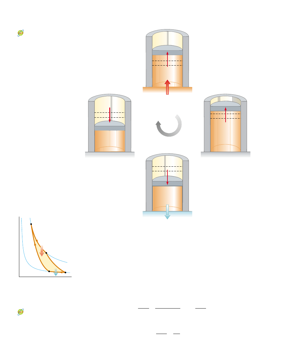
ducting. Four stages of the Carnot cycle are shown in Figure 22.10, and the PV diagram
for the cycle is shown in Figure 22.11. The Carnot cycle consists of two adiabatic
processes and two isothermal processes, all reversible:
1. Process A : B (Fig. 22.10a) is an isothermal expansion at temperature T
h
. The gas
is placed in thermal contact with an energy reservoir at temperature T
h
. During the
expansion, the gas absorbs energy
!Q
h
! from the reservoir through the base of the
cylinder and does work W
AB
in raising the piston.
2. In process B : C (Fig. 22.10b), the base of the cylinder is replaced by a thermally
nonconducting wall, and the gas expands adiabatically—that is, no energy enters or
leaves the system by heat. During the expansion, the temperature of the gas
decreases from T
h
to T
c
and the gas does work W
BC
in raising the piston.
3. In process C : D (Fig. 22.10c), the gas is placed in thermal contact with an energy
reservoir at temperature T
c
and is compressed isothermally at temperature T
c
. Dur-
ing this time, the gas expels energy
!Q
c
! to the reservoir, and the work done by the
piston on the gas is W
CD
.
4. In the final process D : A (Fig. 22.10d), the base of the cylinder is replaced by a
nonconducting wall, and the gas is compressed adiabatically. The temperature of
the gas increases to T
h
, and the work done by the piston on the gas is W
DA
.
Sadi Carnot
French engineer (1796–1832)
Carnot was the first to show the
quantitative relationship between
work and heat. In 1824 he
published his only work—
Reflections on the Motive Power
of Heat—which reviewed the
industrial, political, and economic
importance of the steam engine.
In it, he defined work as “weight
lifted through a height.”
(J.-L. Charmet/Science Photo
Library/Photo Researchers, Inc.)
▲
PITFALL PREVENTION
22.3 Don’t Shop for a
Carnot Engine
The Carnot engine is an idealiza-
tion—do not expect a Carnot
engine to be developed for com-
mercial use. We explore the
Carnot engine only for theoreti-
cal considerations.
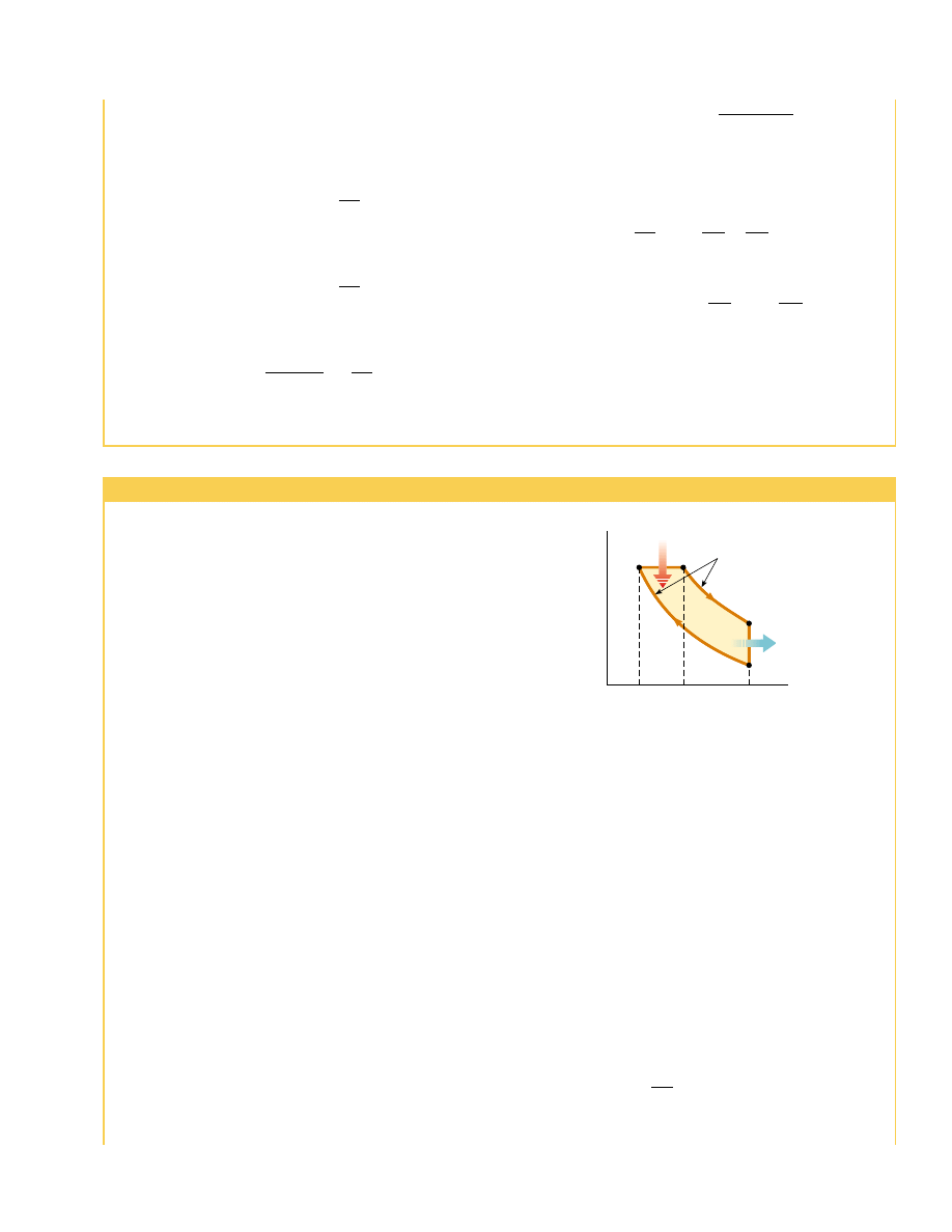
The net work done in this reversible, cyclic process is equal to the area enclosed by
the path ABCDA in Figure 22.11. As we demonstrated in Section 22.1, because the
change in internal energy is zero, the net work W
eng
done by the gas in one cycle
equals the net energy transferred into the system,
!Q
h
! " !Q
c
!. The thermal efficiency
of the engine is given by Equation 22.2:
In Example 22.3, we show that for a Carnot cycle
(22.5)
! Q
c
!
! Q
h
!
!
T
c
T
h
e !
W
eng
! Q
h
!
!
! Q
h
! " ! Q
c
!
! Q
h
!
!
1 "
! Q
c
!
! Q
h
!
676
C H A P T E R 2 2 • Heat Engines, Entropy, and the Second Law of Thermodynamics
Cycle
Energy reservoir at T
c
C
→ D
Isothermal
compression
Q
c
B
→ C
Adiabatic
expansion
Q = 0
(b)
Q = 0
(d)
Energy reservoir at T
h
(a)
A
→ B
Isothermal
expansion
Q
h
D
→ A
Adiabatic
compression
Active Figure 22.10 The Carnot cycle. (a) In process A : B, the gas expands
isothermally while in contact with a reservoir at T
h
. (b) In process B : C, the gas
expands adiabatically (Q ! 0). (c) In process C : D, the gas is compressed
isothermally while in contact with a reservoir at T
c
$
T
h
. (d) In process D : A, the gas
is compressed adiabatically. The arrows on the piston indicate the direction of its
motion during each process.
At the Active Figures link
at http://www.pse6.com, you
can observe the motion of the
piston in the Carnot cycle while
you also observe the cycle on
the PV diagram of Figure 22.11.
V
P
W
eng
D
B
Q
h
T
h
T
c
Q
c
C
A
Active Figure 22.11 PV diagram
for the Carnot cycle. The net work
done W
eng
equals the net energy
transferred into the Carnot engine
in one cycle,
!Q
h
! " !Q
c
!. Note that
%
E
int
!
0 for the cycle.
At the Active Figures link
at http://www.pse6.com, you
can observe the Carnot cycle
on the PV diagram while you
also observe the motion of the
piston in Figure 22.10.

S E C T I O N 2 2 . 4 • The Carnot Engine
677
Hence, the thermal efficiency of a Carnot engine is
(22.6)
This result indicates that
all Carnot engines operating between the same two tem-
peratures have the same efficiency.
5
Equation 22.6 can be applied to any working substance operating in a Carnot cycle
between two energy reservoirs. According to this equation, the efficiency is zero if
T
c
!
T
h
, as one would expect. The efficiency increases as T
c
is lowered and as T
h
is
raised. However, the efficiency can be unity (100%) only if T
c
!
0 K. Such reservoirs
are not available; thus, the maximum efficiency is always less than 100%. In most prac-
tical cases, T
c
is near room temperature, which is about 300 K. Therefore, one usually
strives to increase the efficiency by raising T
h
. Theoretically, a Carnot-cycle heat engine
run in reverse constitutes the most effective heat pump possible, and it determines the
maximum COP for a given combination of hot and cold reservoir temperatures. Using
Equations 22.1 and 22.3, we see that the maximum COP for a heat pump in its heating
mode is
The Carnot COP for a heat pump in the cooling mode is
As the difference between the temperatures of the two reservoirs approaches zero in
this expression, the theoretical COP approaches infinity. In practice, the low tempera-
ture of the cooling coils and the high temperature at the compressor limit the COP to
values below 10.
COP
C
(cooling mode) !
T
c
T
h
"
T
c
!
! Q
h
!
! Q
h
! " ! Q
c
!
!
1
1 "
! Q
c
!
! Q
h
!
!
1
1 "
T
c
T
h
!
T
h
T
h
"
T
c
COP
C
(heating mode) !
!Q
h
!
W
e
C
!
1 "
T
c
T
h
5
In order for the processes in the Carnot cycle to be reversible, they must be carried out
infinitesimally slowly. Thus, although the Carnot engine is the most efficient engine possible, it has
zero power output, because it takes an infinite time interval to complete one cycle! For a real engine,
the short time interval for each cycle results in the working substance reaching a high temperature
lower than that of the hot reservoir and a low temperature higher than that of the cold reservoir. An
engine undergoing a Carnot cycle between this narrower temperature range was analyzed by Curzon
and Ahlborn (Am. J. Phys., 43(1), 22, 1975), who found that the efficiency at maximum power output
depends only on the reservoir temperatures T
c
and T
h
, and is given by e
C - A
!
1 " (T
c
/T
h
)
1/2
. The
Curzon–Ahlborn efficiency e
C-A
provides a closer approximation to the efficiencies of real engines than
does the Carnot efficiency.
Efficiency of a Carnot engine
Quick Quiz 22.4
Three engines operate between reservoirs separated in
temperature by 300 K. The reservoir temperatures are as follows: Engine A:
T
h
!
1 000 K, T
c
!
700 K; Engine B: T
h
!
800 K, T
c
!
500 K ; Engine C: T
h
!
600 K,
T
c
!
300 K. Rank the engines in order of theoretically possible efficiency, from
highest to lowest.

678
C H A P T E R 2 2 • Heat Engines, Entropy, and the Second Law of Thermodynamics
Example 22.3 Efficiency of the Carnot Engine
Show that the efficiency of a heat engine operating in a
Carnot cycle using an ideal gas is given by Equation 22.6.
Solution During the isothermal expansion (process A : B
in Fig. 22.10), the temperature of the gas does not change.
Thus, its internal energy remains constant. The work done
on a gas during an isothermal process is given by Equation
20.13. According to the first law,
In a similar manner, the energy transferred to the cold
reservoir during the isothermal compression C : D is
Dividing the second expression by the first, we find that
We now show that the ratio of the logarithmic quantities is
unity by establishing a relationship between the ratio of vol-
umes. For any quasi-static, adiabatic process, the tempera-
ture and volume are related by Equation 21.20:
(1)
! Q
c
!
! Q
h
!
!
T
c
T
h
ln(V
C
/V
D
)
ln(V
B
/V
A
)
! Q
c
! ! ! "W
CD
! ! nRT
c
ln
V
C
V
D
! Q
h
! ! ! "W
AB
! ! nRT
h
ln
V
B
V
A
Applying this result to the adiabatic processes B : C and
D : A, we obtain
Dividing the first equation by the second, we obtain
Substituting Equation (2) into Equation (1), we find that
the logarithmic terms cancel, and we obtain the relationship
Using this result and Equation 22.2, we see that the thermal
efficiency of the Carnot engine is
which is Equation 22.6, the one we set out to prove.
e
C
!
1 "
! Q
c
!
! Q
h
!
!
1 "
T
c
T
h
! Q
c
!
! Q
h
!
!
T
c
T
h
(2)
V
B
V
A
!
V
C
V
D
(V
B
/V
A
)
* "
1
!
(V
C
/V
D
)
* "
1
T
h
V
A
* "
1
!
T
c
V
D
* "
1
T
h
V
B
* "
1
!
T
c
V
C
* "
1
T
i
V
i
* "
1
!
T
f
V
f
* "
1
Example 22.4 The Steam Engine
A steam engine has a boiler that operates at 500 K. The
energy from the burning fuel changes water to steam, and
this steam then drives a piston. The cold reservoir’s tem-
perature is that of the outside air, approximately 300 K.
What is the maximum thermal efficiency of this steam
engine?
Solution Using Equation 22.6, we find that the maximum
thermal efficiency for any engine operating between these
temperatures is
or
You should note that this is the highest theoretical efficiency
of the engine. In practice, the efficiency is considerably
lower.
What If?
Suppose we wished to increase the theoretical ef-
ficiency of this engine and we could do so by increasing T
h
by
40.0%
0.400
e
C
!
1 "
T
c
T
h
!
1 "
300 K
500 K
!
%
T or by decreasing T
c
by the same %T. Which would be more
effective?
Answer A given %T would have a larger fractional effect on
a smaller temperature, so we would expect a larger change
in efficiency if we alter T
c
by %T. Let us test this numerically.
Increasing T
h
by 50 K, corresponding to T
h
!
550 K, would
give a maximum efficiency of
Decreasing T
c
by 50 K, corresponding to T
c
!
250 K, would
give a maximum efficiency of
While changing T
c
is mathematically more effective, often
changing T
h
is practically more feasible.
e
C
!
1 "
T
c
T
h
!
1 "
250 K
500 K
!
0.500
e
C
!
1 "
T
c
T
h
!
1 "
300 K
550 K
!
0.455
Example 22.5 The Carnot Efficiency
The highest theoretical efficiency of a certain engine is
30.0%. If this engine uses the atmosphere, which has a tem-
perature of 300 K, as its cold reservoir, what is the tempera-
ture of its hot reservoir?
Solution We use the Carnot efficiency to find T
h
:
429 K
T
h
!
T
c
1 " e
C
!
300 K
1 " 0.300
!
e
C
!
1 "
T
c
T
h
S E C T I O N 2 2 . 5 • Gasoline and Diesel Engines
679
22.5 Gasoline and Diesel Engines
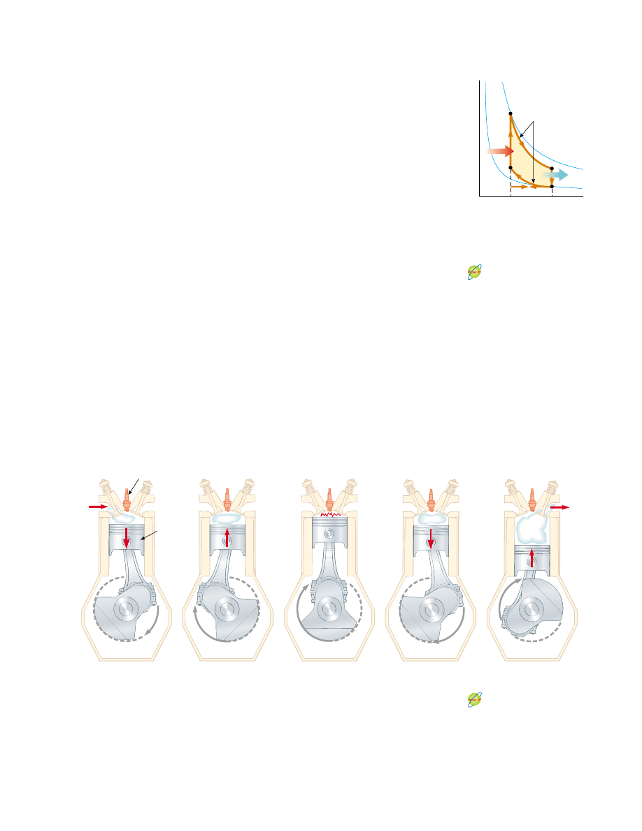
In a gasoline engine, six processes occur in each cycle; five of these are illustrated in
Figure 22.12. In this discussion, we consider the interior of the cylinder above the pis-
ton to be the system that is taken through repeated cycles in the operation of the en-
gine. For a given cycle, the piston moves up and down twice. This represents a four-
stroke cycle consisting of two upstrokes and two downstrokes. The processes in the
cycle can be approximated by the
Otto cycle, shown in the PV diagram in Figure
22.13. In the following discussion, refer to Figure 22.12 for the pictorial representation
of the strokes and to Figure 22.13 for the significance on the PV diagram of the letter
designations below:
1. During the intake stroke O : A (Fig. 22.12a), the piston moves downward, and a
gaseous mixture of air and fuel is drawn into the cylinder at atmospheric pressure.
In this process, the volume increases from V
2
to V
1
. This is the energy input part of
the cycle—energy enters the system (the interior of the cylinder) as potential en-
ergy stored in the fuel.
2. During the compression stroke A : B (Fig. 22.12b), the piston moves upward, the
air–fuel mixture is compressed adiabatically from volume V
1
to volume V
2
, and the
temperature increases from T
A
to T
B
. The work done on the gas is positive, and its
value is equal to the negative of the area under the curve AB in Figure 22.13.
3. In process B : C, combustion occurs when the spark plug fires (Fig. 22.12c). This
is not one of the strokes of the cycle because it occurs in a very short period of time
while the piston is at its highest position. The combustion represents a rapid trans-
formation from potential energy stored in chemical bonds in the fuel to internal
energy associated with molecular motion, which is related to temperature. During
this time, the pressure and temperature in the cylinder increase rapidly, with the
temperature rising from T
B
to T
C
. The volume, however, remains approximately
constant because of the short time interval. As a result, approximately no work is
done on or by the gas. We can model this process in the PV diagram (Fig. 22.13) as
Air
and
fuel
Spark plug
Piston
Intake
(a)
Compression
(b)
Spark
(c)
Power
(d)
Exhaust
Exhaust
(e)
Active Figure 22.12 The four-stroke cycle of a conventional gasoline engine. The
arrows on the piston indicate the direction of its motion during each process. (a) In
the intake stroke, air and fuel enter the cylinder. (b) The intake valve is then closed,
and the air–fuel mixture is compressed by the piston. (c) The mixture is ignited by the
spark plug, with the result that the temperature of the mixture increases at essentially
constant volume. (d) In the power stroke, the gas expands against the piston.
(e) Finally, the residual gases are expelled, and the cycle repeats.
At the Active Figures link
at http://www.pse6.com, you
can observe the motion of the
piston and crankshaft while you
also observe the cycle on the
PV diagram of Figure 22.13.
V
P
C
Q
h
B
D
T
C
Q
c
Adiabatic
processes
V
2
V
1
O
A
T
A
Active Figure 22.13 PV diagram
for the Otto cycle, which
approximately represents the
processes occurring in an internal
combustion engine.
At the Active Figures link
at http://www.pse6.com, you can
observe the Otto cycle on the
PV diagram while you observe
the motion of the piston and
crankshaft in Figure 22.12.

that process in which the energy
!Q
h
! enters the system. (However, in reality this
process is a conversion of energy already in the cylinder from process O : A.)
4. In the power stroke C : D (Fig. 22.12d), the gas expands adiabatically from V
2
to V
1
.
This expansion causes the temperature to drop from T
C
to T
D
. Work is done by the
gas in pushing the piston downward, and the value of this work is equal to the area
under the curve CD.
5. In the process D : A (not shown in Fig. 22.12), an exhaust valve is opened as the
piston reaches the bottom of its travel, and the pressure suddenly drops for a short
time interval. During this interval, the piston is almost stationary and the volume is
approximately constant. Energy is expelled from the interior of the cylinder and
continues to be expelled during the next process.
6. In the final process, the exhaust stroke A : O (Fig. 22.12e), the piston moves upward
while the exhaust valve remains open. Residual gases are exhausted at atmospheric
pressure, and the volume decreases from V
1
to V
2
. The cycle then repeats.
If the air–fuel mixture is assumed to be an ideal gas, then the efficiency of the
Otto cycle is
(Otto cycle)
(22.7)
where * is the ratio of the molar specific heats C
P
/C
V
for the fuel–air mixture and
V
1
/V
2
is the
compression ratio. Equation 22.7, which we derive in Example 22.6,
shows that the efficiency increases as the compression ratio increases. For a typical
compression ratio of 8 and with * ! 1.4, we predict a theoretical efficiency of 56% for
an engine operating in the idealized Otto cycle. This value is much greater than that
achieved in real engines (15% to 20%) because of such effects as friction, energy trans-
fer by conduction through the cylinder walls, and incomplete combustion of the
air–fuel mixture.
Diesel engines operate on a cycle similar to the Otto cycle but do not employ a
spark plug. The compression ratio for a diesel engine is much greater than that for a
gasoline engine. Air in the cylinder is compressed to a very small volume, and, as a con-
sequence, the cylinder temperature at the end of the compression stroke is very high.
At this point, fuel is injected into the cylinder. The temperature is high enough for the
fuel–air mixture to ignite without the assistance of a spark plug. Diesel engines are
more efficient than gasoline engines because of their greater compression ratios and
resulting higher combustion temperatures.
e ! 1 "
1
(V
1
/V
2
)
*"
1
680
C H A P T E R 2 2 • Heat Engines, Entropy, and the Second Law of Thermodynamics
Example 22.6 Efficiency of the Otto Cycle
Show that the thermal efficiency of an engine operating in
an idealized Otto cycle (see Figs. 22.12 and 22.13) is given
by Equation 22.7. Treat the working substance as an ideal
gas.
Solution First, let us calculate the work done on the gas
during each cycle. No work is done during processes B : C
and D : A. The work done on the gas during the adiabatic
compression A : B is positive, and the work done on the
gas during the adiabatic expansion C : D is negative. The
value of the net work done equals the area of the shaded re-
gion bounded by the closed curve in Figure 22.13. Because
the change in internal energy for one cycle is zero, we see
from the first law that the net work done during one cycle
equals the net energy transfer to the system:
W
eng
!
! Q
h
! " ! Q
c
!
Because processes B : C and D : A take place at constant
volume, and because the gas is ideal, we find from the defin-
ition of molar specific heat (Eq. 21.8) that
Using these expressions together with Equation 22.2, we ob-
tain for the thermal efficiency
We can simplify this expression by noting that processes
A : B and C : D are adiabatic and hence obey Equation
21.20. For the two adiabatic processes, then,
C : D
:
T
C
V
C
*"
1
!
T
D
V
D
*"
1
A : B
:
T
A
V
A
*"
1
!
T
B
V
B
*"
1
(1)
e !
W
eng
! Q
h
!
!
1 "
! Q
c
!
! Q
h
!
!
1 "
T
D
"
T
A
T
C
"
T
B
! Q
h
! ! nC
V
(T
C
"
T
B
)
and
! Q
c
! ! nC
V
(T
D
"
T
A
)
S E C T I O N 2 2 . 5 • Gasoline and Diesel Engines
681
Using these equations and relying on the fact that
V
A
!
V
D
!
V
1
and V
B
!
V
C
!
V
2
, we find that
Subtracting Equation (2) from Equation (3) and rearrang-
ing, we find that
Substituting Equation (4) into Equation (1), we obtain for
the thermal efficiency
(4)
T
D
"
T
A
T
C
"
T
B
!
"
V
2
V
1
#
*"
1
(3)
T
D
!
T
C
"
V
2
V
1
#
*"
1
T
D
V
1
*"
1
!
T
C
V
2
*"
1
(2)
T
A
!
T
B
"
V
2
V
1
#
*"
1
T
A
V
1
*"
1
!
T
B
V
2
*"
1
which is Equation 22.7.
We can also express this efficiency in terms of tempera-
tures by noting from Equations (2) and (3) that
Therefore, Equation (5) becomes
During the Otto cycle, the lowest temperature is T
A
and the
highest temperature is T
C
. Therefore, the efficiency of
a Carnot engine operating between reservoirs at these
two temperatures, which is given by the expression
e
C
!
1 " (T
A
/T
C
), is greater than the efficiency of the Otto
cycle given by Equation (6), as expected.
(6)
e ! 1 "
T
A
T
B
!
1 "
T
D
T
C
"
V
2
V
1
#
*"
1
!
T
A
T
B
!
T
D
T
C
(5)
e ! 1 "
1
(V
1
/V
2
)
*"
1
Application Models of Gasoline and Diesel Engines
We can use the thermodynamic principles discussed in this
and earlier chapters to model the performance of gasoline
and diesel engines. In both types of engine, a gas is first
compressed in the cylinders of the engine and then the
fuel–air mixture is ignited. Work is done on the gas during
compression, but significantly more work is done on the
piston by the mixture as the products of combustion expand
in the cylinder. The power of the engine is transferred from
the piston to the crankshaft by the connecting rod.
Two important quantities of either engine are the
displacement volume, which is the volume displaced by
the piston as it moves from the bottom to the top of the
cylinder, and the compression ratio r, which is the ratio of
the maximum and minimum volumes of the cylinder, as
discussed earlier. Most gasoline and diesel engines operate
with a four-stroke cycle (intake, compression, power,
exhaust), in which the net work of the intake and exhaust
strokes can be considered negligible. Therefore, power is
developed only once for every two revolutions of the
crankshaft (see Fig. 22.12).
In a diesel engine, only air (and no fuel) is present in
the cylinder at the beginning of the compression. In the
idealized diesel cycle of Figure 22.14, air in the cylinder
undergoes an adiabatic compression from A to B. Starting
at B, fuel is injected into the cylinder. The high
temperature of the mixture causes combustion of the
fuel–air mixture. Fuel continues to be injected in such a
way that during the time interval while the fuel is being
injected, the fuel–air mixture undergoes a constant-
pressure expansion to an intermediate volume V
C
(B : C).
At C, the fuel injection is cut off and the power stroke is an
adiabatic expansion back to V
D
!
V
A
(C : D). The exhaust
valve is opened, and a constant-volume output of energy
occurs (D : A) as the cylinder empties.
To simplify our calculations, we assume that the
mixture in the cylinder is air modeled as an ideal gas.
We use specific heats c instead of molar specific heats
C and assume constant values for air at 300 K. We express
the specific heats and the universal gas constant in
terms of unit masses rather than moles. Thus, c
V
!
0.718 kJ/kg ( K, c
P
!
1.005 kJ/kg ( K, * ! c
P
/c
V
!
1.40, and
R ! c
P
"
c
V
!
0.287 kJ/kg ( K ! 0.287 kPa ( m
3
/kg ( K.
A 3.00-L Gasoline Engine
Let us calculate the power delivered by a six-cylinder gasoline
engine that has a displacement volume of 3.00 L operating at
4 000 rpm and having a compression ratio of r ! 9.50. The
air–fuel mixture enters a cylinder at atmospheric pressure and
an ambient temperature of 27°C. During combustion, the
mixture reaches a temperature of 1 350°C.
First, let us calculate the work done in an individual
cylinder. Using the initial pressure P
A
!
100 kPa, and the
initial temperature T
A
!
300 K, we calculate the initial volume
and the mass of the air–fuel mixture. We know that the ratio
of the initial and final volumes is the compression ratio,
We also know that the difference in volumes is the
displacement volume. The 3.00-L rating of the engine is the
V
A
V
B
!
r ! 9.50
Adiabatic
processes
A
B
C
D
P
V
Q
h
Q
c
V
2
= V
B
V
C
V
1
= V
A
Figure 22.14 PV diagram for an ideal diesel engine.

682
C H A P T E R 2 2 • Heat Engines, Entropy, and the Second Law of Thermodynamics
total displacement volume for all six cylinders. Thus, for one
cylinder,
Solving these two equations simultaneously, we find the
initial and final volumes:
Using the ideal gas law (in the form PV ! mRT, because
we are using the universal gas constant in terms of mass
rather than moles), we can find the mass of the air–fuel
mixture:
Process A : B (see Fig. 22.13) is an adiabatic compression,
and this means that PV
*
!
constant; hence,
Using the ideal gas law, we find that the temperature after
the compression is
In process B : C, the combustion that transforms the
potential energy in chemical bonds into internal energy of
molecular motion occurs at constant volume; thus, V
C
!
V
B
.
Combustion causes the temperature to increase to T
C
!
1 350°C ! 1 623 K. Using this value and the ideal gas law, we
can calculate P
C
:
Process C : D is an adiabatic expansion; the pressure after
the expansion is
Using the ideal gas law again, we find the final temperature:
Now that we have the temperatures at the beginning and end
of each process of the cycle, we can calculate the net energy
transfer and net work done in each cylinder every two cycles:
!
660 K
T
D
!
P
D
V
D
mR
!
(220 kPa)(0.559 ' 10
"
3
m
3
)
(6.49 ' 10
"
4
kg)(0.287 kPa(m
3
/kg(K)
!
(5.14 ' 10
3
kPa)
"
1
9.50
#
1.40
!
220 kPa
P
D
!
P
C
"
V
C
V
D
#
*
!
P
C
"
V
B
V
A
#
*
!
P
C
"
1
r
#
*
!
5.14 ' 10
3
kPa
!
(6.49 ' 10
"
4
kg)(0.287 kPa(m
3
/kg(K)(1 623 K)
(0.588 ' 10
"
4
m
3
)
P
C
!
mRT
C
V
C
!
739 K
T
B
!
P
B
V
B
mR
!
(2.34 ' 10
3
kPa)(0.588 ' 10
"
4
m
3
)
(6.49 ' 10
"
4
kg) (0.287 kPa(m
3
/kg(K)
!
2.34 ' 10
3
kPa
P
B
!
P
A
"
V
A
V
B
#
*
!
P
A
(r)
*
!
(100 kPa)(9.50)
1.40
P
B
V
B
*
!
P
A
V
A
*
!
6.49 ' 10
"
4
kg
m !
P
A
V
A
RT
A
!
(100 kPa)(0.559 ' 10
"
3
m
3
)
(0.287 kPa(m
3
/kg(K)(300 K)
V
A
!
0.559 ' 10
"
3
m
3
V
B
!
0.588 ' 10
"
4
m
3
V
A
"
V
B
!
3.00 L
6
!
0.500 ' 10
"
3
m
3
From Equation 22.2, the efficiency is e ! W
net
/|Q
in
| ! 59%.
(We can also use Equation 22.7 to calculate the efficiency
directly from the compression ratio.)
Recalling that power is delivered every other revolution
of the crankshaft, we find that the net power for the six-
cylinder engine operating at 4 000 rpm is
A 2.00-L Diesel Engine
Let us calculate the power delivered by a four-cylinder diesel
engine that has a displacement volume of 2.00 L and is operat-
ing at 3 000 rpm. The compression ratio is r ! V
A
/V
B
!
22.0,
and the
cutoff ratio, which is the ratio of the volume change
during the constant-pressure process B : C in Figure 22.14, is
r
c
!
V
C
/V
B
!
2.00. The air enters each cylinder at the
beginning of the compression cycle at atmospheric pressure
and at an ambient temperature of 27°C.
Our model of the diesel engine is similar to our model
of the gasoline engine except that now the fuel is injected at
point B and the mixture self-ignites near the end of the
compression cycle A : B, when the temperature reaches
the ignition temperature. We assume that the energy input
occurs in the constant-pressure process B : C, and that the
expansion process continues from C to D with no further
energy transfer by heat.
Let us calculate the work done in an individual cylinder
that has an initial volume of V
A
!
(2.00 ' 10
"
3
m
3
)/4 !
0.500 ' 10
"
3
m
3
. Because the compression ratio is quite high,
we approximate the maximum cylinder volume to be the
displacement volume. Using the initial pressure P
A
!
100 kPa
and initial temperature T
A
!
300 K , we can calculate the mass
of the air in the cylinder using the ideal gas law:
Process A : B
is an adiabatic compression, so
PV
*
!
constant; thus,
Using the ideal gas law, we find that the temperature of the
air after the compression is
!
1.03 ' 10
3
K
T
B
!
P
B
V
B
mR
!
(7.58 ' 10
3
kPa)(0.500 ' 10
"
3
m
3
)(1/22.0)
(5.81 ' 10
"
4
kg)(0.287 kPa(m
3
/kg(K)
P
B
!
P
A
"
V
A
V
B
#
*
!
(100 kPa)(22.0)
1.40
!
7.58 ' 10
3
kPa
P
B
V
B
*
!
P
A
V
A
*
!
5.81 ' 10
"
4
kg
m !
P
A
V
A
RT
A
!
(100 kPa)(0.500 ' 10
"
3
m
3
)
(0.287 kPa(m
3
/kg(K)(300 K)
!
48.8 kW ! 65 hp
!
net
!
6(
1
2
rev)[(4 000 rev/min)(1 min/60 s)](0.244 kJ)
W
net
!
! Q
in
!
"
! Q
out
! ! 0.244 kJ
!
0.168 kJ
!
(6.49 ' 10
"
4
kg)(0.718 kJ/kg(K)(660 K " 300 K)
! Q
c
! ! ! Q
out
! ! mc
V
(T
D
"
T
A
)
!
0.412 kJ
!
(6.49 ' 10
"
4
kg)(0.718 kJ/kg(K)(1 623 " 739 K)
! Q
h
! ! ! Q
in
! ! mc
V
(T
C
"
T
B
)

22.6 Entropy
The zeroth law of thermodynamics involves the concept of temperature, and the first
law involves the concept of internal energy. Temperature and internal energy are both
state variables—that is, they can be used to describe the thermodynamic state of a sys-
tem. Another state variable—this one related to the second law of thermodynamics—is
entropy S. In this section we define entropy on a macroscopic scale as it was first ex-
pressed by Clausius in 1865.
Entropy was originally formulated as a useful concept in thermodynamics; however,
its importance grew as the field of statistical mechanics developed because the analyti-
cal techniques of statistical mechanics provide an alternative means of interpreting
entropy and a more global significance to the concept. In statistical mechanics, the
behavior of a substance is described in terms of the statistical behavior of its atoms and
molecules. One of the main results of this treatment is that
isolated systems tend
toward disorder and that entropy is a measure of this disorder. For example,
consider the molecules of a gas in the air in your room. If half of the gas molecules
had velocity vectors of equal magnitude directed toward the left and the other half had
velocity vectors of the same magnitude directed toward the right, the situation would
be very ordered. However, such a situation is extremely unlikely. If you could actually
view the molecules, you would see that they move haphazardly in all directions, bump-
ing into one another, changing speed upon collision, some going fast and others going
slowly. This situation is highly disordered.
The cause of the tendency of an isolated system toward disorder is easily explained.
To do so, we distinguish between microstates and macrostates of a system. A
microstate is
a particular configuration of the individual constituents of the system. For example,
the description of the ordered velocity vectors of the air molecules in your room refers
to a particular microstate, and the more likely haphazard motion is another mi-
crostate—one that represents disorder. A
macrostate is a description of the conditions
of the system from a macroscopic point of view and makes use of macroscopic variables
such as pressure, density, and temperature for gases.
For any given macrostate of the system, a number of microstates are possible. For
example, the macrostate of a four on a pair of dice can be formed from the possible
microstates 1-3, 2-2, and 3-1. It is assumed that all microstates are equally probable.
However, when all possible macrostates are examined, it is found that macrostates
S E C T I O N 2 2 . 6 • Entropy
683
▲
PITFALL PREVENTION
22.4 Entropy Is Abstract
Entropy is one of the most ab-
stract notions in physics, so fol-
low the discussion in this and the
subsequent sections very care-
fully. Do not confuse energy with
entropy—even though the names
sound similar, they are very dif-
ferent concepts.
Process B : C is a constant-pressure expansion; thus,
P
C
!
P
B
. We know from the cutoff ratio of 2.00 that the
volume doubles in this process. According to the ideal gas
law, a doubling of volume in an isobaric process results in
a doubling of the temperature, so
Process C : D is an adiabatic expansion; therefore,
We find the temperature at D from the ideal gas law:
!
792 K
T
D
!
P
D
V
D
mR
!
(264 kPa)(0.500 ' 10
"
3
m
3
)
(5.81 ' 10
"
4
kg)(0.287 kPa(m
3
/kg(K)
!
264 kPa
! (7.57 ' 10
3
kPa)
"
2.00
22.0
#
1.40
P
D
!
P
C
"
V
C
V
D
#
*
!
P
C
"
V
C
V
B
V
B
V
D
#
*
!
P
C
"
r
c
1
r
#
*
T
C
!
2T
B
!
2.06 ' 10
3
K
Now that we have the temperatures at the beginning and
the end of each process, we can calculate the net energy
transfer by heat and the net work done in each cylinder
every two cycles:
The efficiency is e ! W
net
/
!Q
in
! ! 66%.
The net power for the four-cylinder engine operating at
3 000 rpm is
Modern engine design goes beyond this very simple
thermodynamic treatment, which uses idealized cycles.
!
39.6 kW ! 53 hp
!
net
!
4(
1
2
rev)[(3 000 rev/min)(1 min/60 s)](0.396 kJ)
W
net
!
! Q
in
! " ! Q
out
! ! 0.396 kJ
! Q
c
! ! ! Q
out
! ! mc
V
(T
D
"
T
A
) ! 0.205 kJ
! Q
h
! ! ! Q
in
! ! mc
P
(T
C
"
T
B
) ! 0.601 kJ

associated with disorder have far more possible microstates than those associated with
order. For example, there is only one microstate associated with the macrostate of
a royal flush in a poker hand of five spades, laid out in order from ten to ace
(Fig. 22.15a). This is a highly ordered hand. However, there are many microstates (the
set of five individual cards in a poker hand) associated with a worthless hand in poker
(Fig. 22.15b).
The probability of being dealt the royal flush in spades is exactly the same as the
probability of being dealt any particular worthless hand. Because there are so many
worthless hands, however, the probability of a macrostate of a worthless hand is far
larger than the probability of a macrostate of a royal flush in spades.
We can also imagine ordered macrostates and disordered macrostates in physical
processes, not just in games of dice and poker. The probability of a system moving in
time from an ordered macrostate to a disordered macrostate is far greater than the prob-
ability of the reverse, because there are more microstates in a disordered macrostate.
If we consider a system and its surroundings to include the entire Universe, then
the Universe is always moving toward a macrostate corresponding to greater disor-
der. Because entropy is a measure of disorder, an alternative way of stating this is
the entropy of the Universe increases in all real processes. This is yet another
statement of the second law of thermodynamics that can be shown to be equivalent
to the Kelvin–Planck and Clausius statements.
The original formulation of entropy in thermodynamics involves the transfer of
energy by heat during a reversible process. Consider any infinitesimal process in which
a system changes from one equilibrium state to another. If dQ
r
is the amount of energy
transferred by heat when the system follows a reversible path between the states, then
the change in entropy dS is equal to this amount of energy for the reversible process
divided by the absolute temperature of the system:
(22.8)
We have assumed that the temperature is constant because the process is infinitesimal.
Because we have claimed that entropy is a state variable,
the change in entropy dur-
ing a process depends only on the end points and therefore is independent of
the actual path followed. Consequently, the entropy change for an irreversible
process can be determined by calculating the entropy change for a reversible
process that connects the same initial and final states.
The subscript r on the quantity dQ
r
is a reminder that the transferred energy is to
be measured along a reversible path, even though the system may actually have fol-
lowed some irreversible path. When energy is absorbed by the system, dQ
r
is positive
and the entropy of the system increases. When energy is expelled by the system, dQ
r
is
negative and the entropy of the system decreases. Note that Equation 22.8 defines not
entropy but rather the change in entropy. Hence, the meaningful quantity in describing
a process is the change in entropy.
dS !
dQ
r
T
684
C H A P T E R 2 2 • Heat Engines, Entropy, and the Second Law of Thermodynamics
Figure 22.15 (a) A royal flush is a
highly ordered poker hand with low
probability of occurring.
(b) A disordered and worthless
poker hand. The probability of this
particular hand occurring is the same
as that of the royal flush. There are
so many worthless hands, however,
that the probability of being dealt a
worthless hand is much higher than
that of a royal flush.
Quick Quiz 22.5
Suppose that you select four cards at random from a stan-
dard deck of playing cards and end up with a macrostate of four deuces. How many
microstates are associated with this macrostate?
Quick Quiz 22.6
Suppose you pick up two cards at random from a standard
deck of playing cards and end up with a macrostate of two aces. How many microstates
are associated with this macrostate?
a and b George Semple
(a)
(b)

To calculate the change in entropy for a finite process, we must recognize that T is
generally not constant. If dQ
r
is the energy transferred by heat when the system follows
an arbitrary reversible process between the same initial and final states as the irre-
versible process, then
(22.9)
As with an infinitesimal process, the change in entropy %S of a system going
from one state to another has the same value for all paths connecting the two states.
That is, the finite change in entropy %S of a system depends only on the properties
of the initial and final equilibrium states. Thus, we are free to choose a particular
reversible path over which to evaluate the entropy in place of the actual path, as
long as the initial and final states are the same for both paths. This point is explored
further in Section 22.7.
%
S !
%
f
i
dS !
%
f
i
dQ
r
T
Let us consider the changes in entropy that occur in a Carnot heat engine that
operates between the temperatures T
c
and T
h
. In one cycle, the engine takes in energy
Q
h
from the hot reservoir and expels energy Q
c
to the cold reservoir. These energy
transfers occur only during the isothermal portions of the Carnot cycle; thus, the con-
stant temperature can be brought out in front of the integral sign in Equation 22.9.
The integral then simply has the value of the total amount of energy transferred by
heat. Thus, the total change in entropy for one cycle is
where the negative sign represents the fact that
!Q
c
! is positive, but this term must rep-
resent energy leaving the engine. In Example 22.3 we showed that, for a Carnot engine,
Using this result in the previous expression for %S, we find that the total change in
entropy for a Carnot engine operating in a cycle is zero:
Now consider a system taken through an arbitrary (non-Carnot) reversible cycle.
Because entropy is a state variable—and hence depends only on the properties of a
given equilibrium state—we conclude that %S ! 0 for any reversible cycle. In general,
we can write this condition in the mathematical form
(22.10)
where the symbol indicates that the integration is over a closed path.
&
&
dQ
r
T
!
0
%
S ! 0
! Q
c
!
! Q
h
!
!
T
c
T
h
%
S !
! Q
h
!
T
h
"
! Q
c
!
T
c
S E C T I O N 2 2 . 6 • Entropy
685
Quick Quiz 22.7
Which of the following is true for the entropy change of a
system that undergoes a reversible, adiabatic process? (a) %S $ 0 (b) %S ! 0 (c) %S # 0
Quick Quiz 22.8
An ideal gas is taken from an initial temperature T
i
to a
higher final temperature T
f
along two different reversible paths: Path A is at constant
pressure; Path B is at constant volume. The relation between the entropy changes of
the gas for these paths is (a) %S
A
# %
S
B
(b) %S
A
! %
S
B
(c) % S
A
$ %
S
B
.
Change in entropy for a finite
process

Quasi-Static, Reversible Process for an Ideal Gas
Suppose that an ideal gas undergoes a quasi-static, reversible process from an initial
state having temperature T
i
and volume V
i
to a final state described by T
f
and V
f
. Let us
calculate the change in entropy of the gas for this process.
Writing the first law of thermodynamics in differential form and rearranging the
terms, we have dQ
r
!
dE
int
"
dW, where dW ! " P dV. For an ideal gas, recall that
dE
int
!
nC
V
dT (Eq. 21.12), and from the ideal gas law, we have P = nRT/V. Therefore,
we can express the energy transferred by heat in the process as
We cannot integrate this expression as it stands because the last term contains two
variables, T and V. However, if we divide all terms by T, each of the terms on the
right-hand side depends on only one variable:
(22.11)
Assuming that C
V
is constant over the process, and integrating Equation 22.11 from the
initial state to the final state, we obtain
(22.12)
This expression demonstrates mathematically what we argued earlier—%S depends only
on the initial and final states and is independent of the path between the states. We can
claim this because we have not specified the path taken between the initial and final
states. We have only required that the path be reversible. Also, note in Equation 22.12
that %S can be positive or negative, depending on the values of the initial and final vol-
umes and temperatures. Finally, for a cyclic process (T
i
!
T
f
and V
i
!
V
f
), we see from
Equation 22.12 that % S ! 0. This is further evidence that entropy is a state variable.
%
S !
%
f
i
dQ
r
T
!
nC
V
ln
T
f
T
i
&
nR
ln
V
f
V
i
dQ
r
T
!
nC
V
dT
T
&
nR
dV
V
dQ
r
!
d
E
int
&
P
dV ! nC
V
dT & nRT
dV
V
686
C H A P T E R 2 2 • Heat Engines, Entropy, and the Second Law of Thermodynamics
Example 22.7 Change in Entropy—Melting
A solid that has a latent heat of fusion L
f
melts at a tempera-
ture T
m
.
(A)
Calculate the change in entropy of this substance when
a mass m of the substance melts.
Solution Let us assume that the melting occurs so slowly
that it can be considered a reversible process. In this case
the temperature can be regarded as constant and equal to
T
m
. Making use of Equations 22.9 and that for the latent
heat of fusion Q ! mL
f
(Eq. 20.6, choosing the positive sign
because energy is entering the ice), we find that
Note that we are able to remove T
m
from the integral be-
cause the process is modeled as isothermal. Note also that
%
S is positive.
(B)
Estimate the value of the change in entropy of an ice
cube when it melts.
Solution Let us assume an ice tray makes cubes that are
about 3 cm on a side. The volume per cube is then (very
mL
f
T
m
%
S !
%
dQ
r
T
!
1
T
m
%
dQ !
Q
T
m
!
roughly) 30 cm
3
. This much liquid water has a mass of 30 g.
From Table 20.2 we find that the latent heat of fusion of ice
is 3.33 ' 10
5
J/kg. Substituting these values into our answer
for part (A), we find that
We retain only one significant figure, in keeping with the
nature of our estimations.
What If?
Suppose you did not have Equation 22.9 avail-
able so that you could not calculate an entropy change. How
could you argue from the statistical description of entropy
that the changes in entropy for parts (A) and (B) should be
positive?
Answer When a solid melts, its entropy increases because
the molecules are much more disordered in the liquid state
than they are in the solid state. The positive value for %S
also means that the substance in its liquid state does not
spontaneously transfer energy from itself to the surround-
ings and freeze because to do so would involve a sponta-
neous increase in order and a decrease in entropy.
4 ' 10
1
J/K
%
S !
mL
f
T
m
!
(0.03 kg)(3.33 ' 10
5
J/kg)
273 K
!

22.7 Entropy Changes in Irreversible Processes
By definition, a calculation of the change in entropy for a system requires information
about a reversible path connecting the initial and final equilibrium states. To calculate
changes in entropy for real (irreversible) processes, we must remember that entropy
(like internal energy) depends only on the state of the system. That is, entropy is a state
variable. Hence, the change in entropy when a system moves between any two equilib-
rium states depends only on the initial and final states.
We can calculate the entropy change in some irreversible process between two
equilibrium states by devising a reversible process (or series of reversible processes)
between the same two states and computing
for the reversible process.
In irreversible processes, it is critically important that we distinguish between Q , the
actual energy transfer in the process, and Q
r
, the energy that would have been
transferred by heat along a reversible path. Only Q
r
is the correct value to be used in
calculating the entropy change.
As we show in the following examples, the change in entropy for a system and its
surroundings is always positive for an irreversible process. In general, the total en-
tropy—and therefore the disorder—always increases in an irreversible process. Keeping
these considerations in mind, we can state the second law of thermodynamics as follows:
The total entropy of an isolated system that undergoes a change cannot decrease.
Furthermore,
if the process is irreversible, then the total entropy of an isolated
system always increases. In a reversible process, the total entropy of an isolated
system remains constant.
When dealing with a system that is not isolated from its surroundings, remember
that the increase in entropy described in the second law is that of the system and its
surroundings. When a system and its surroundings interact in an irreversible process,
the increase in entropy of one is greater than the decrease in entropy of the other.
Hence, we conclude that
the change in entropy of the Universe must be greater
than zero for an irreversible process and equal to zero for a reversible process.
Ultimately, the entropy of the Universe should reach a maximum value. At this value,
the Universe will be in a state of uniform temperature and density. All physical, chemi-
cal, and biological processes will cease because a state of perfect disorder implies that
no energy is available for doing work. This gloomy state of affairs is sometimes referred
to as the heat death of the Universe.
%
S ! %dQ
r
/T
Entropy Change in Thermal Conduction
Let us now consider a system consisting of a hot reservoir and a cold reservoir that are
in thermal contact with each other and isolated from the rest of the Universe. A
process occurs during which energy Q is transferred by heat from the hot reservoir at
temperature T
h
to the cold reservoir at temperature T
c
. The process as described is ir-
reversible, and so we must find an equivalent reversible process. Let us assume that the
objects are connected by a poor thermal conductor whose temperature spans the
range from T
c
to T
h
. This conductor transfers energy slowly, and its state does not
change during the process. Under this assumption, the energy transfer to or from each
object is reversible, and we may set Q ! Q
r
.
Because the cold reservoir absorbs energy Q , its entropy increases by Q /T
c
. At the
same time, the hot reservoir loses energy Q , and so its entropy change is " Q /T
h
.
Because T
h
#
T
c
, the increase in entropy of the cold reservoir is greater than the
S E C T I O N 2 2 . 7 • Entropy Changes in Irreversible Processes
687
Quick Quiz 22.9
True or false: The entropy change in an adiabatic process
must be zero because Q ! 0.

decrease in entropy of the hot reservoir. Therefore, the change in entropy of the sys-
tem (and of the Universe) is greater than zero:
%
S
U
!
Q
T
c
&
"
Q
T
h
#
0
Entropy Change in a Free Expansion
Let us again consider the adiabatic free expansion of a gas occupying an initial volume
V
i
(Fig. 22.16). In this situation, a membrane separating the gas from an evacuated
region is broken, and the gas expands (irreversibly) to a volume V
f
. What are the
changes in entropy of the gas and of the Universe during this process?
The process is neither reversible nor quasi-static. The work done by the gas against
the vacuum is zero, and because the walls are insulating, no energy is transferred by
heat during the expansion. That is, W ! 0 and Q ! 0. Using the first law, we see that
the change in internal energy is zero. Because the gas is ideal, E
int
depends on temper-
ature only, and we conclude that %T ! 0 or T
i
!
T
f
.
To apply Equation 22.9, we cannot use Q ! 0, the value for the irreversible process,
but must instead find Q
r
; that is, we must find an equivalent reversible path that shares
the same initial and final states. A simple choice is an isothermal, reversible expansion
in which the gas pushes slowly against a piston while energy enters the gas by heat from
a reservoir to hold the temperature constant. Because T is constant in this process,
Equation 22.9 gives
For an isothermal process, the first law of thermodynamics specifies that
is equal to
the negative of the work done on the gas during the expansion from V
i
to V
f
, which is
given by Equation 20.13. Using this result, we find that the entropy change for the gas is
(22.13)
%
S ! nR ln
V
f
V
i
%
f
i
dQ
r
%
S !
%
f
i
dQ
r
T
!
1
T
%
f
i
dQ
r
688
C H A P T E R 2 2 • Heat Engines, Entropy, and the Second Law of Thermodynamics
Example 22.8 Which Way Does the Energy Go?
A large, cold object is at 273 K, and a second large, hot ob-
ject is at 373 K. Show that it is impossible for a small amount
of energy—for example, 8.00 J—to be transferred sponta-
neously by heat from the cold object to the hot one without
a decrease in the entropy of the Universe and therefore a
violation of the second law.
Solution We assume that, during the energy transfer, the
two objects do not undergo a temperature change. This is
not a necessary assumption; we make it only to avoid compli-
cating the situation by having to use integral calculus in our
calculations. The entropy change of the hot object is
The cold object loses energy, and its entropy change is
We consider the two objects to be isolated from the rest of
the Universe. Thus, the entropy change of the Universe is
just that of our two-object system, which is
%
S
c
!
Q
r
T
c
!
"
8.00 J
273 K
! "
0.029 3 J/K
%
S
h
!
Q
r
T
h
!
8.00 J
373 K
!
0.021 4 J/K
This decrease in entropy of the Universe is in violation of
the second law. That is,
the spontaneous transfer of en-
ergy by heat from a cold to a hot object cannot occur.
Suppose energy were to continue to transfer sponta-
neously from a cold object to a hot object, in violation of the
second law. We can describe this impossible energy transfer
in terms of disorder. Before the transfer, a certain degree of
order is associated with the different temperatures of the ob-
jects. The hot object’s molecules have a higher average
energy than the cold object’s molecules. If energy sponta-
neously transfers from the cold object to the hot object,
then, over a period of time, the cold object will become
colder and the hot object will become hotter. The differ-
ence in average molecular energy will become even greater;
this would represent an increase in order for the system and
a violation of the second law.
In comparison, the process that does occur naturally is
the transfer of energy from the hot object to the cold object.
In this process, the difference in average molecular energy
decreases; this represents a more random distribution of
energy and an increase in disorder.
%
S
U
! %
S
c
& %
S
h
! "
0.007 9 J/K
Insulating
wall
Membrane
Vacuum
Gas at T
i
Figure 22.16 Adiabatic free
expansion of a gas. When the
membrane separating the gas from
the evacuated region is ruptured,
the gas expands freely and
irreversibly. As a result, it occupies
a greater final volume. The
container is thermally insulated
from its surroundings; thus, Q ! 0.

Because V
f
#
V
i
, we conclude that %S is positive. This positive result indicates that
both the entropy and the disorder of the gas increase as a result of the irreversible,
adiabatic expansion.
It is easy to see that the gas is more disordered after the expansion. Instead of
being concentrated in a relatively small space, the molecules are scattered over a larger
region.
Because the free expansion takes place in an insulated container, no energy is
transferred by heat from the surroundings. (Remember that the isothermal, reversible
expansion is only a replacement process that we use to calculate the entropy change for
the gas; it is not the actual process.) Thus, the free expansion has no effect on the sur-
roundings, and the entropy change of the surroundings is zero. Thus, the entropy
change for the Universe is positive; this is consistent with the second law.
Entropy Change in Calorimetric Processes
A substance of mass m
1
, specific heat c
1
, and initial temperature T
c
is placed in thermal
contact with a second substance of mass m
2
, specific heat c
2
, and initial temperature
T
h
#
T
c
. The two substances are contained in a calorimeter so that no energy is lost to
the surroundings. The system of the two substances is allowed to reach thermal equilib-
rium. What is the total entropy change for the system?
First, let us calculate the final equilibrium temperature T
f
. Using the techniques of
Section 20.2—namely, Equation 20.5, Q
cold
! "
Q
hot
, and Equation 20.4, Q ! mc %T,
we obtain
Solving for T
f
, we have
(22.14)
The process is irreversible because the system goes through a series of nonequilib-
rium states. During such a transformation, the temperature of the system at any time is
not well defined because different parts of the system have different temperatures.
However, we can imagine that the hot substance at the initial temperature T
h
is slowly
cooled to the temperature T
f
as it comes into contact with a series of reservoirs differ-
ing infinitesimally in temperature, the first reservoir being at T
h
and the last being at
T
f
. Such a series of very small changes in temperature would approximate a reversible
process. We imagine doing the same thing for the cold substance. Applying Equation
22.9 and noting that dQ ! mc dT for an infinitesimal change, we have
where we have assumed that the specific heats remain constant. Integrating, we find that
(22.15)
where T
f
is given by Equation 22.14. If Equation 22.14 is substituted into Equation
22.15, we can show that one of the terms in Equation 22.15 is always positive and the
other is always negative. (You may want to verify this for yourself.) The positive term is
always greater than the negative term, and this results in a positive value for %S. Thus,
we conclude that the entropy of the Universe increases in this irreversible process.
Finally, you should note that Equation 22.15 is valid only when no mixing of differ-
ent substances occurs, because a further entropy increase is associated with the increase
in disorder during the mixing. If the substances are liquids or gases and mixing occurs,
the result applies only if the two fluids are identical, as in the following example.
%
S ! m
1
c
1
ln
T
f
T
c
&
m
2
c
2
ln
T
f
T
h
%
S !
%
1
dQ
cold
T
&
%
2
dQ
hot
T
!
m
1
c
1
%
T
f
T
c
dT
T
&
m
2
c
2
%
T
f
T
h
dT
T
T
f
!
m
1
c
1
T
c
&
m
2
c
2
T
h
m
1
c
1
&
m
2
c
2
m
1
c
1
(T
f
"
T
c
) ! "m
2
c
2
(T
f
"
T
h
)
m
1
c
1
%T
c
! "
m
2
c
2
%T
h
S E C T I O N 2 2 . 7 • Entropy Changes in Irreversible Processes
689

690
C H A P T E R 2 2 • Heat Engines, Entropy, and the Second Law of Thermodynamics
6
This section was adapted from A. Hudson and R. Nelson, University Physics, Philadelphia, Saunders
College Publishing, 1990.
Example 22.9 Calculating !S for a Calorimetric Process
Suppose that 1.00 kg of water at 0.00°C is mixed with an
equal mass of water at 100°C. After equilibrium is reached,
the mixture has a uniform temperature of 50.0°C. What is
the change in entropy of the system?
Solution We can calculate the change in entropy from
Equation 22.15 using the given values m
1
!
m
2
!
1.00 kg,
c
1
!
c
2
!
4 186 J/kg ( K, T
1
!
273 K, T
2
!
373 K, and
T
f
!
323 K:
%
S ! m
1
c
1
ln
T
f
T
1
&
m
2
c
2
ln
T
f
T
2
!
That is, as a result of this irreversible process, the increase
in entropy of the cold water is greater than the decrease in
entropy of the warm water. Consequently, the increase in
entropy of the system is 102 J/K.
704 J/K "602 J/K ! 102 J/K
&
(1.00 kg)(4 186 J/kg(K)
ln
"
323 K
373 K
#
%
S ! (1.00 kg)(4 186 J/kg(K)
ln
"
323 K
273 K
#
22.8 Entropy on a Microscopic Scale
6
As we have seen, we can approach entropy by relying on macroscopic concepts. We can
also treat entropy from a microscopic viewpoint through statistical analysis of molecu-
lar motions. We now use a microscopic model to investigate once again the free expan-
sion of an ideal gas, which was discussed from a macroscopic point of view in the pre-
ceding section.
In the kinetic theory of gases, gas molecules are represented as particles moving
randomly. Let us suppose that the gas is initially confined to a volume V
i
, as shown in
Figure 22.17a. When the partition separating V
i
from a larger container is removed,
the molecules eventually are distributed throughout the greater volume V
f
(Fig.
22.17b). For a given uniform distribution of gas in the volume, there are a large num-
ber of equivalent microstates, and we can relate the entropy of the gas to the number
of microstates corresponding to a given macrostate.
We count the number of microstates by considering the variety of molecular loca-
tions involved in the free expansion. The instant after the partition is removed (and
before the molecules have had a chance to rush into the other half of the container), all
the molecules are in the initial volume. We assume that each molecule occupies some
microscopic volume V
m
. The total number of possible locations of a single molecule in a
macroscopic initial volume V
i
is the ratio w
i
!
V
i
/V
m
, which is a huge number. We use w
i
here to represent the number of ways that the molecule can be placed in the volume, or
the number of microstates, which is equivalent to the number of available locations. We
assume that the probabilities of a molecule occupying any of these locations are equal.
As more molecules are added to the system, the number of possible ways that the
molecules can be positioned in the volume multiplies. For example, if we consider two
molecules, for every possible placement of the first, all possible placements of the sec-
ond are available. Thus, there are w
1
ways of locating the first molecule, and for each
of these, there are w
2
ways of locating the second molecule. The total number of ways
of locating the two molecules is w
1
w
2
.
Neglecting the very small probability of having two molecules occupy the same loca-
tion, each molecule may go into any of the V
i
/V
m
locations, and so the number of ways
of locating N molecules in the volume becomes
(W
i
is not to be
confused with work.) Similarly, when the volume is increased to V
f
, the number of ways
of locating N molecules increases to
The ratio of the number of
ways of placing the molecules in the volume for the initial and final configurations is
W
f
!
w
f
N
!
(V
f
/V
m
)
N
.
W
i
!
w
i
N
!
(V
i
/V
m
)
N
.
Vacuum
V
i
(a)
V
f
(b)
Figure 22.17 In a free expansion,
the gas is allowed to expand into a
region that was previously
evacuated.

If we now take the natural logarithm of this equation and multiply by Boltzmann’s con-
stant, we find that
where we have used the equality N ! nN
A
. We know from Equation 19.11 that N
A
k
B
is
the universal gas constant R ; thus, we can write this equation as
(22.16)
From Equation 22.13 we know that when n mol of a gas undergoes a free expansion
from V
i
to V
f
, the change in entropy is
(22.17)
Note that the right-hand sides of Equations 22.16 and 22.17 are identical. Thus, from
the left-hand sides, we make the following important connection between entropy and
the number of microstates for a given macrostate:
(22.18)
The more microstates there are that correspond to a given macrostate, the greater is
the entropy of that macrostate. As we have discussed previously, there are many more
microstates associated with disordered macrostates than with ordered macrostates.
Thus, Equation 22.18 indicates mathematically that
entropy is a measure of disor-
der. Although in our discussion we used the specific example of the free expansion of
an ideal gas, a more rigorous development of the statistical interpretation of entropy
would lead us to the same conclusion.
We have stated that individual microstates are equally probable. However, because
there are far more microstates associated with a disordered macrostate than with an or-
dered microstate, a disordered macrostate is much more probable than an ordered one.
Figure 22.18 shows a real-world example of this concept. There are two possible
macrostates for the carnival game—winning a goldfish and winning a black fish. Be-
cause only one jar in the array of jars contains a black fish, only one possible microstate
corresponds to the macrostate of winning a black fish. A large number of microstates
are described by the coin’s falling into a jar containing a goldfish. Thus, for the
macrostate of winning a goldfish, there are many equivalent microstates. As a result,
the probability of winning a goldfish is much greater than the probability of winning a
black fish. If there are 24 goldfish and 1 black fish, the probability of winning the black
fish is 1 in 25. This assumes that all microstates have the same probability, a situation
S
$ k
B
ln
W
S
f
"
S
i
!
nR
ln
"
V
f
V
i
#
k
B
ln
W
f
"
k
B
ln
W
i
!
nR
ln
"
V
f
V
i
#
k
B
ln
"
W
f
W
i
#
!
nN
A
k
B
ln
"
V
f
V
i
#
W
f
W
i
!
(V
f
/V
m
)
N
(V
i
/V
m
)
N
!
"
V
f
V
i
#
N
S E C T I O N 2 2 . 8 • Entropy on a Microscopic Scale
691
Entropy (microscopic definition)
Figure 22.18 By tossing a coin into a jar, the carnival-goer can win the fish in the jar. It
is more likely that the coin will land in a jar containing a goldfish than in the one
containing the black fish.

that may not be quite true for the situation shown in Figure 22.18. For example, if you
are an accurate coin tosser and you are aiming for the edge of the array of jars, then
the probability of the coin’s landing in a jar near the edge is likely to be greater than
the probability of its landing in a jar near the center.
Let us consider a similar type of probability problem for 100 molecules in a con-
tainer. At any given moment, the probability of one molecule being in the left part of the
container shown in Figure 22.19a as a result of random motion is . If there are two mol-
ecules, as shown in Figure 22.19b, the probability of both being in the left part is
or 1 in 4. If there are three molecules (Fig. 22.19c), the probability of all of them
being in the left portion at the same moment is
, or 1 in 8. For 100 independently
moving molecules, the probability that the 50 fastest ones will be found in the left part at
any moment is
. Likewise, the probability that the remaining 50 slower molecules
will be found in the right part at any moment is
. Therefore, the probability of find-
ing this fast-slow separation as a result of random motion is the product
!
, which corresponds to about 1 in 10
30
. When this calculation is extrapolated from
100 molecules to the number in 1 mol of gas (6.02 ' 10
23
), the ordered arrangement is
found to be extremely improbable!
"
1
2
#
100
"
1
2
#
50
"
1
2
#
50
"
1
2
#
50
"
1
2
#
50
"
1
2
#
3
"
1
2
#
2
1
2
692
C H A P T E R 2 2 • Heat Engines, Entropy, and the Second Law of Thermodynamics
(a)
(b)
(c)
Active Figure 22.19 (a) One molecule in a two-sided container has a 1-in-2 chance of
being on the left side. (b) Two molecules have a 1-in-4 chance of being on the left side at
the same time. (c) Three molecules have a 1-in-8 chance of being on the left side at the
same time.
Conceptual Example 22.10 Let’s Play Marbles!
Suppose you have a bag of 100 marbles. Fifty of the marbles
are red, and 50 are green. You are allowed to draw four mar-
bles from the bag according to the following rules. Draw one
marble, record its color, and return it to the bag. Shake the
bag and then draw another marble. Continue this process
until you have drawn and returned four marbles. What are
the possible macrostates for this set of events? What is the
most likely macrostate? What is the least likely macrostate?
Solution Because each marble is returned to the bag before
the next one is drawn, and the bag is shaken, the probability
of drawing a red marble is always the same as the probability
of drawing a green one. All the possible microstates and
macrostates are shown in Table 22.1. As this table indicates,
there is only one way to draw a macrostate of four red marbles,
and so there is only one microstate for that macrostate. How-
ever, there are four possible microstates that correspond to
the macrostate of one green marble and three red marbles; six
microstates that correspond to two green marbles and two red
marbles; four microstates that correspond to three green mar-
bles and one red marble; and one microstate that corresponds
to four green marbles. The most likely, and most disordered,
Interactive
At the Active Figures link
at http://www.pse6.com, you
can choose the number of
molecules to put in the
container and measure the
probability of all of them being
in the left hand side.

S E C T I O N 2 2 . 8 • Entropy on a Microscopic Scale
693
Macrostate
Possible Microstates
Total Number of Microstates
All R
RRRR
1
1G, 3R
RRRG, RRGR, RGRR, GRRR
4
2G, 2R
RRGG, RGRG, GRRG, RGGR,
GRGR, GGRR
6
3G, 1R
GGGR, GGRG, GRGG, RGGG
4
All G
GGGG
1
Possible Results of Drawing Four Marbles from a Bag
Table 22.1
Example 22.11 Adiabatic Free Expansion—One Last Time
Let us verify that the macroscopic and microscopic ap-
proaches to the calculation of entropy lead to the same con-
clusion for the adiabatic free expansion of an ideal gas. Sup-
pose that an ideal gas expands to four times its initial
volume. As we have seen for this process, the initial and final
temperatures are the same.
(A)
Using a macroscopic approach, calculate the entropy
change for the gas.
(B)
Using statistical considerations, calculate the change in
entropy for the gas and show that it agrees with the answer
you obtained in part (A).
Solution
(A)
Using Equation 22.13, we have
(B)
The number of microstates available to a single mole-
cule in the initial volume V
i
is
. For N molecules,
w
i
!
V
i
/V
m
nR
ln
4
%
S ! nR
ln
"
V
f
V
i
#
!
nR
ln
"
4V
i
V
i
#
!
the number of available microstates is
The number of microstates for all N molecules in the final
volume V
f
!
4V
i
is
Thus, the ratio of the number of final microstates to initial
microstates is
Using Equation 22.18, we obtain
The answer is the same as that for part (A), which dealt with
macroscopic parameters.
What If?
In part (A) we used Equation 22.13, which was
based on a reversible isothermal process connecting the
initial and final states. What if we were to choose a different
reversible process? Would we arrive at the same result?
Answer We must arrive at the same result because entropy is
a state variable. For example, consider the two-step process
in Figure 22.20—a reversible adiabatic expansion from
V
i
to 4V
i
, (A : B) during which the temperature drops from
T
1
to T
2
, and a reversible isovolumetric process (B : C) that
takes the gas back to the initial temperature T
1
.
During the reversible adiabatic process, %S ! 0 because
Q
r
!
0. During the reversible isovolumetric process (B : C),
we have from Equation 22.9,
nR
ln
4
! k
B
ln(4
N
) ! Nk
B
ln
4 !
%
S ! k
B
lnW
f
"
k
B
lnW
i
!
k
B
ln
"
W
f
W
i
#
W
f
W
i
!
4
N
W
f
!
"
V
f
V
m
#
N
!
"
4V
i
V
m
#
N
W
i
!
w
i
N
!
"
V
i
V
m
#
N
V
P
V
i
4V
i
B
C
A
T
1
T
2
Figure 22.20 (Example 22.11) A gas expands to four times its
initial volume and back to the initial temperature by means of a
two-step process.
Explore the generation of microstates and macrostates at the Interactive Worked Example link at http://www.pse6.com.
macrostate—two red marbles and two green marbles—corre-
sponds to the largest number of microstates. The least likely,
most ordered macrostates—four red marbles or four green
marbles—correspond to the smallest number of microstates.

694
C H A P T E R 2 2 • Heat Engines, Entropy, and the Second Law of Thermodynamics
A
heat engine is a device that takes in energy by heat and, operating in a cyclic
process, expels a fraction of that energy by means of work. The net work done by a
heat engine in carrying a working substance through a cyclic process (%E
int
!
0) is
(22.1)
where
!Q
h
! is the energy taken in from a hot reservoir and !Q
c
! is the energy expelled
to a cold reservoir.
The
thermal efficiency e of a heat engine is
(22.2)
The
second law of thermodynamics can be stated in the following two ways:
• It is impossible to construct a heat engine that, operating in a cycle, produces no
effect other than the input of energy by heat from a reservoir and the performance
of an equal amount of work (the Kelvin–Planck statement).
• It is impossible to construct a cyclical machine whose sole effect is to transfer en-
ergy continuously by heat from one object to another object at a higher tempera-
ture without the input of energy by work (the Clausius statement).
In a
reversible process, the system can be returned to its initial conditions along
the same path on a PV diagram, and every point along this path is an equilibrium state.
A process that does not satisfy these requirements is
irreversible. Carnot’s theorem
states that no real heat engine operating (irreversibly) between the temperatures T
c
and T
h
can be more efficient than an engine operating reversibly in a Carnot cycle be-
tween the same two temperatures.
The
thermal efficiency of a heat engine operating in the Carnot cycle is
(22.6)
The second law of thermodynamics states that when real (irreversible) processes
occur, the degree of disorder in the system plus the surroundings increases. When a
process occurs in an isolated system, the state of the system becomes more disordered.
The measure of disorder in a system is called
entropy S. Thus, another way in which
the second law can be stated is
• The entropy of the Universe increases in all real processes.
The
change in entropy dS of a system during a process between two infinitesimally
separated equilibrium states is
(22.8)
where dQ
r
is the energy transfer by heat for a reversible process that connects the
initial and final states. The change in entropy of a system during an arbitrary process
dS !
dQ
r
T
e
C
!
1 "
T
c
T
h
e !
W
eng
! Q
h
!
!
1 "
! Q
c
!
! Q
h
!
W
eng
!
! Q
h
! " ! Q
c
!
S U M M A R Y
Take a practice test for
this chapter by clicking on
the Practice Test link at
http://www.pse6.com.
Now, we can find the relationship of temperature T
2
to T
1
from Equation 21.20 for the adiabatic process:
T
1
T
2
!
"
4V
i
V
i
#
*"
1
!
(4)
*"
1
%
S !
%
f
i
dQ
r
T
!
%
C
B
nC
V
dT
T
!
nC
V
ln
"
T
1
T
2
#
Thus,
and we do indeed obtain the exact same result for the
entropy change.
! nC
V
"
C
P
C
V
"
1
#
ln
4 ! n(C
P
"
C
V
)
ln
4 ! nR
ln
4
%
S ! nC
V
ln
(4)
*"
1
!
nC
V
(* " 1)
ln
4

Questions
695
What are some factors that affect the efficiency of automo-
bile engines?
2. In practical heat engines, which are we better able to con-
trol: the temperature of the hot reservoir or the tempera-
ture of the cold reservoir? Explain.
A steam-driven turbine is one major component of an
electric power plant. Why is it advantageous to have the
temperature of the steam as high as possible?
4. Is it possible to construct a heat engine that creates no
thermal pollution? What does this tell us about environ-
mental considerations for an industrialized society?
5. Does the second law of thermodynamics contradict or cor-
rect the first law? Argue for your answer.
6. “The first law of thermodynamics says you can’t really win,
and the second law says you can’t even break even.”
Explain how this statement applies to a particular device
or process; alternatively, argue against the statement.
7. In solar ponds constructed in Israel, the Sun’s energy is
concentrated near the bottom of a salty pond. With the
3.
1.
proper layering of salt in the water, convection is pre-
vented, and temperatures of 100°C may be reached. Can
you estimate the maximum efficiency with which useful
energy can be extracted from the pond?
8. Can a heat pump have a coefficient of performance less
than unity? Explain.
9. Give various examples of irreversible processes that occur
in nature. Give an example of a process in nature that is
nearly reversible.
10. A heat pump is to be installed in a region where the aver-
age outdoor temperature in the winter months
is " 20°C. In view of this, why would it be advisable to
place the outdoor compressor unit deep in the ground?
Why are heat pumps not commonly used for heating in
cold climates?
The device shown in Figure Q22.11, called a thermoelec-
tric converter, uses a series of semiconductor cells to
convert internal energy to electric potential energy, which
we will study in Chapter 25. In the photograph at the left,
11.
Q U E S T I O N S
Figure Q22.11
Courtesy of P
ASCO Scientific Company
between an initial state and a final state is
(22.9)
The value of %S for the system is the same for all paths connecting the initial and
final states. The change in entropy for a system undergoing any reversible, cyclic
process is zero, and when such a process occurs, the entropy of the Universe remains
constant.
From a microscopic viewpoint, the entropy of a given macrostate is defined as
(22.18)
where k
B
is Boltzmann’s constant and W is the number of microstates of the system cor-
responding to the macrostate.
S
$ k
B
ln
W
%
S !
%
f
i
dQ
r
T

696
C H A P T E R 2 2 • Heat Engines, Entropy, and the Second Law of Thermodynamics
both legs of the device are at the same temperature, and
no electric potential energy is produced. However, when
one leg is at a higher temperature than the other, as in
the photograph on the right, electric potential energy is
produced as the device extracts energy from the hot
reservoir and drives a small electric motor. (a) Why does
the temperature differential produce electric potential
energy in this demonstration? (b) In what sense does this
intriguing experiment demonstrate the second law of
thermodynamics?
12. Discuss three common examples of natural processes that
involve an increase in entropy. Be sure to account for all
parts of each system under consideration.
Discuss the change in entropy of a gas that expands (a) at
constant temperature and (b) adiabatically.
14. A thermodynamic process occurs in which the entropy of a
system changes by " 8.0 J/K. According to the second law
of thermodynamics, what can you conclude about the en-
tropy change of the environment?
15. If a supersaturated sugar solution is allowed to evaporate
slowly, sugar crystals form in the container. Hence, sugar
molecules go from a disordered form (in solution) to a
highly ordered crystalline form. Does this process violate
the second law of thermodynamics? Explain.
13.
16. How could you increase the entropy of 1 mol of a metal
that is at room temperature? How could you decrease its
entropy?
17. Suppose your roommate is “Mr. Clean” and tidies up your
messy room after a big party. Because your roommate is
creating more order, does this represent a violation of the
second law of thermodynamics?
18. Discuss the entropy changes that occur when you (a) bake
a loaf of bread and (b) consume the bread.
19. “Energy is the mistress of the Universe and entropy is her
shadow.” Writing for an audience of general readers, argue
for this statement with examples. Alternatively, argue for
the view that entropy is like a decisive hands-on executive
instantly determining what will happen, while energy is
like a wretched back-office bookkeeper telling us how little
we can afford.
20. A classmate tells you that it is just as likely for all the air mol-
ecules in the room you are both in to be concentrated in
one corner (with the rest of the room being a vacuum) as it
is for the air molecules to be distributed uniformly about
the room in their current state. Is this a true statement?
Why doesn’t the situation he describes actually happen?
21. If you shake a jar full of jellybeans of different sizes, the
larger beans tend to appear near the top, and the smaller
ones tend to fall to the bottom. Why? Does this process vio-
late the second law of thermodynamics?
Section 22.1 Heat Engines and the Second Law
of Thermodynamics
1. A heat engine takes in 360 J of energy from a hot reservoir
and performs 25.0 J of work in each cycle. Find (a) the ef-
ficiency of the engine and (b) the energy expelled to the
cold reservoir in each cycle.
2. A heat engine performs 200 J of work in each cycle and
has an efficiency of 30.0%. For each cycle, how much
energy is (a) taken in and (b) expelled by heat?
A particular heat engine has a useful power output of
5.00 kW and an efficiency of 25.0%. The engine expels
8 000 J of exhaust energy in each cycle. Find (a) the
energy taken in during each cycle and (b) the time inter-
val for each cycle.
4.
Heat engine X takes in four times more energy by heat from
the hot reservoir than heat engine Y. Engine X delivers two
times more work, and it rejects seven times more energy by
heat to the cold reservoir than heat engine Y. Find the effi-
ciency of (a) heat engine X and (b) heat engine Y.
5.
A multicylinder gasoline engine in an airplane, operating
at 2 500 rev/min, takes in energy 7.89 ' 10
3
J and ex-
hausts 4.58 ' 10
3
J for each revolution of the crankshaft.
3.
(a) How many liters of fuel does it consume in 1.00 h of
operation if the heat of combustion is 4.03 ' 10
7
J/L?
(b) What is the mechanical power output of the engine?
Ignore friction and express the answer in horsepower.
(c) What is the torque exerted by the crankshaft on the
load? (d) What power must the exhaust and cooling sys-
tem transfer out of the engine?
6.
Suppose a heat engine is connected to two energy reser-
voirs, one a pool of molten aluminum (660°C) and the
other a block of solid mercury (" 38.9°C). The engine
runs by freezing 1.00 g of aluminum and melting 15.0 g of
mercury during each cycle. The heat of fusion of alu-
minum is 3.97 ' 10
5
J/kg; the heat of fusion of mercury is
1.18 ' 10
4
J/kg. What is the efficiency of this engine?
Section 22.2 Heat Pumps and Refrigerators
7. A refrigerator has a coefficient of performance equal to
5.00. The refrigerator takes in 120 J of energy from a cold
reservoir in each cycle. Find (a) the work required in each
cycle and (b) the energy expelled to the hot reservoir.
8.
A refrigerator has a coefficient of performance of 3.00.
The ice tray compartment is at " 20.0°C, and the room
1,
2
,
3
= straightforward, intermediate, challenging
= full solution available in the Student Solutions Manual and Study Guide
= coached solution with hints available at http://www.pse6.com
= computer useful in solving problem
= paired numerical and symbolic problems
P R O B L E M S

temperature is 22.0°C. The refrigerator can convert 30.0 g
of water at 22.0°C to 30.0 g of ice at " 20.0°C each minute.
What input power is required? Give your answer in watts.
9. In 1993 the federal government instituted a requirement
that all room air conditioners sold in the United States
must have an energy efficiency ratio (EER) of 10 or higher.
The EER is defined as the ratio of the cooling capacity of
the air conditioner, measured in Btu/h, to its electrical
power requirement in watts. (a) Convert the EER of 10.0 to
dimensionless form, using the conversion 1 Btu ! 1 055 J.
(b) What is the appropriate name for this dimensionless
quantity? (c) In the 1970s it was common to find room air
conditioners with EERs of 5 or lower. Compare the operat-
ing costs for 10 000-Btu/h air conditioners with EERs of
5.00 and 10.0. Assume that each air conditioner operates
for 1 500 h during the summer in a city where electricity
costs 10.0¢ per kWh.
Section 22.3 Reversible and Irreversible Processes
Section 22.4 The Carnot Engine
10. A Carnot engine has a power output of 150 kW. The en-
gine operates between two reservoirs at 20.0°C and 500°C.
(a) How much energy does it take in per hour? (b) How
much energy is lost per hour in its exhaust?
One of the most efficient heat engines ever built is a steam
turbine in the Ohio valley, operating between 430°C and
1 870°C on energy from West Virginia coal to produce
electricity for the Midwest. (a) What is its maximum theo-
retical efficiency? (b) The actual efficiency of the engine is
42.0%. How much useful power does the engine deliver if
it takes in 1.40 ' 10
5
J of energy each second from its hot
reservoir?
12.
A heat engine operating between 200°C and 80.0°C achieves
20.0% of the maximum possible efficiency. What energy
input will enable the engine to perform 10.0 kJ of work?
An ideal gas is taken through a Carnot cycle. The
isothermal expansion occurs at 250°C, and the isothermal
compression takes place at 50.0°C. The gas takes in 1 200 J
of energy from the hot reservoir during the isothermal ex-
pansion. Find (a) the energy expelled to the cold reservoir
in each cycle and (b) the net work done by the gas in each
cycle.
14. The exhaust temperature of a Carnot heat engine is
300°C. What is the intake temperature if the efficiency of
the engine is 30.0%?
15.
A Carnot heat engine uses a steam boiler at 100°C as the
high-temperature reservoir. The low-temperature reservoir
is the outside environment at 20.0°C. Energy is exhausted
to the low-temperature reservoir at the rate of 15.4 W.
(a) Determine the useful power output of the heat engine.
(b) How much steam will it cause to condense in the high-
temperature reservoir in 1.00 h?
16. A power plant operates at a 32.0% efficiency during the
summer when the sea water used for cooling is at 20.0°C.
The plant uses 350°C steam to drive turbines. If the plant’s
efficiency changes in the same proportion as the ideal effi-
13.
11.
ciency, what would be the plant’s efficiency in the winter,
when the sea water is 10.0°C?
17.
Argon enters a turbine at a rate of 80.0 kg/min, a temper-
ature of 800°C and a pressure of 1.50 MPa. It expands adi-
abatically as it pushes on the turbine blades and exits at
pressure 300 kPa. (a) Calculate its temperature at exit.
(b) Calculate the (maximum) power output of the turning
turbine. (c) The turbine is one component of a model
closed-cycle gas turbine engine. Calculate the maximum
efficiency of the engine.
18.
An electric power plant that would make use of the tem-
perature gradient in the ocean has been proposed. The
system is to operate between 20.0°C (surface water temper-
ature) and 5.00°C (water temperature at a depth of about
1 km). (a) What is the maximum efficiency of such a
system? (b) If the useful power output of the plant is
75.0 MW, how much energy is taken in from the warm
reservoir per hour? (c) In view of your answer to part
(a), do you think such a system is worthwhile? Note that
the “fuel” is free.
19.
Here is a clever idea. Suppose you build a two-engine
device such that the exhaust energy output from one heat
engine is the input energy for a second heat engine. We
say that the two engines are running in series. Let e
1
and e
2
represent the efficiencies of the two engines. (a) The
overall efficiency of the two-engine device is defined as
the total work output divided by the energy put into the
first engine by heat. Show that the overall efficiency is
given by
e ! e
1
&
e
2
"
e
1
e
2
(b) What If? Assume the two engines are Carnot engines.
Engine 1 operates between temperatures T
h
and T
i
. The
gas in engine 2 varies in temperature between T
i
and T
c
.
In terms of the temperatures, what is the efficiency of the
combination engine? (c) What value of the intermediate
temperature T
i
will result in equal work being done by
each of the two engines in series? (d) What value of T
i
will
result in each of the two engines in series having the same
efficiency?
20.
A 20.0%-efficient real engine is used to speed up a train
from rest to 5.00 m/s. It is known that an ideal (Carnot)
engine using the same cold and hot reservoirs would accel-
erate the same train from rest to a speed of 6.50 m/s using
the same amount of fuel. The engines use air at 300 K as a
cold reservoir. Find the temperature of the steam serving
as the hot reservoir.
21.
A firebox is at 750 K, and the ambient temperature is 300 K.
The efficiency of a Carnot engine doing 150 J of work as
it transports energy between these constant-temperature
baths is 60.0%. The Carnot engine must take in energy
150 J/0.600 ! 250 J from the hot reservoir and must put
out 100 J of energy by heat into the environment. To follow
Carnot’s reasoning, suppose that some other heat engine S
could have efficiency 70.0%. (a) Find the energy input and
wasted energy output of engine S as it does 150 J of work.
(b) Let engine S operate as in part (a) and run the Carnot
engine in reverse. Find the total energy the firebox puts out
as both engines operate together, and the total energy trans-
Problems
697

ferred to the environment. Show that the Clausius state-
ment of the second law of thermodynamics is violated.
(c) Find the energy input and work output of engine S as it
puts out exhaust energy of 100 J. (d) Let engine S operate
as in (c) and contribute 150 J of its work output to running
the Carnot engine in reverse. Find the total energy the fire-
box puts out as both engines operate together, the total
work output, and the total energy transferred to the envi-
ronment. Show that the Kelvin–Planck statement of the sec-
ond law is violated. Thus our assumption about the effi-
ciency of engine S must be false. (e) Let the engines
operate together through one cycle as in part (d). Find the
change in entropy of the Universe. Show that the entropy
statement of the second law is violated.
22.
At point A in a Carnot cycle, 2.34 mol of a monatomic
ideal gas has a pressure of 1 400 kPa, a volume of 10.0 L,
and a temperature of 720 K. It expands isothermally to
point B, and then expands adiabatically to point C where
its volume is 24.0 L. An isothermal compression brings it
to point D, where its volume is 15.0 L. An adiabatic process
returns the gas to point A. (a) Determine all the unknown
pressures, volumes and temperatures as you fill in the
following table:
26.
A heat pump, shown in Figure P22.26, is essentially an air
conditioner installed backward. It extracts energy from
colder air outside and deposits it in a warmer room. Sup-
pose that the ratio of the actual energy entering the room
to the work done by the device’s motor is 10.0% of the the-
oretical maximum ratio. Determine the energy entering
the room per joule of work done by the motor, given that
the inside temperature is 20.0°C and the outside tempera-
ture is " 5.00°C.
How much work does an ideal Carnot refrigerator
require to remove 1.00 J of energy from helium at 4.00 K
and reject this energy to a room-temperature (293-K)
environment?
28. A refrigerator maintains a temperature of 0°C in the cold
compartment with a room temperature of 25.0°C. It
removes energy from the cold compartment at the rate of
8 000 kJ/h. (a) What minimum power is required to
operate the refrigerator? (b) The refrigerator exhausts
energy into the room at what rate?
29. If a 35.0%-efficient Carnot heat engine (Fig. 22.2) is run in
reverse so as to form a refrigerator (Fig. 22.5), what would
be this refrigerator’s coefficient of performance?
30.
Two Carnot engines have the same efficiency. One engine
runs in reverse as a heat pump, and the other runs in reverse
as a refrigerator. The coefficient of performance of the heat
pump is 1.50 times the coefficient of performance of the
refrigerator. Find (a) the coefficient of performance of the
refrigerator, (b) the coefficient of performance of the heat
pump, and (c) the efficiency of each heat engine.
Section 22.5 Gasoline and Diesel Engines
In a cylinder of an automobile engine, just after combus-
tion, the gas is confined to a volume of 50.0 cm
3
and has
an initial pressure of 3.00 ' 10
6
Pa. The piston moves out-
ward to a final volume of 300 cm
3
, and the gas expands
without energy loss by heat. (a) If * ! 1.40 for the gas,
what is the final pressure? (b) How much work is done by
the gas in expanding?
32. A gasoline engine has a compression ratio of 6.00 and
uses a gas for which * ! 1.40. (a) What is the efficiency
31.
27.
698
C H A P T E R 2 2 • Heat Engines, Entropy, and the Second Law of Thermodynamics
Q
h
Inside
T
h
Outside
T
c
Q
c
Heat
pump
Figure P22.26
P
V
T
A
1 400 kPa
10.0 L
720 K
B
C
24.0 L
D
15.0 L
(b) Find the energy added by heat, the work done by the
engine, and the change in internal energy for each of the
steps A : B, B : C, C : D, and D : A. (c) Calculate the
efficiency W
net
/Q
h
. Show that it is equal to 1 " T
C
/T
A
,
the Carnot efficiency.
23. What is the coefficient of performance of a refrigerator
that operates with Carnot efficiency between temperatures
"
3.00°C and & 27.0°C?
24. What is the maximum possible coefficient of performance
of a heat pump that brings energy from outdoors at
"
3.00°C into a 22.0°C house? Note that the work done to
run the heat pump is also available to warm up the house.
An ideal refrigerator or ideal heat pump is equivalent to a
Carnot engine running in reverse. That is, energy Q
c
is
taken in from a cold reservoir and energy Q
h
is rejected to
a hot reservoir. (a) Show that the work that must be sup-
plied to run the refrigerator or heat pump is
(b) Show that the coefficient of performance of the ideal
refrigerator is
COP !
T
c
T
h
"
T
c
W !
T
h
"
T
c
T
c
Q
c
25.

Q (input)
W (output)
%
E
int
A
:
B
B
:
C
C
:
D
D
:
A
ABCDA
of the engine if it operates in an idealized Otto cycle?
(b) What If ? If the actual efficiency is 15.0%, what
fraction of the fuel is wasted as a result of friction and
energy losses by heat that could by avoided in a re-
versible engine? (Assume complete combustion of the
air–fuel mixture.)
33. A 1.60-L gasoline engine with a compression ratio of 6.20
has a useful power output of 102 hp. Assuming the en-
gine operates in an idealized Otto cycle, find the energy
taken in and the energy exhausted each second. Assume
the fuel–air mixture behaves like an ideal gas with
* !
1.40.
34.
The compression ratio of an Otto cycle, as shown in Figure
22.13, is V
A
/V
B
!
8.00. At the beginning A of the compres-
sion process, 500 cm
3
of gas is at 100 kPa and 20.0°C. At
the beginning of the adiabatic expansion the temperature
is T
C
!
750°C. Model the working fluid as an ideal gas
with E
int
!
nC
V
T ! 2.50nRT and * ! 1.40. (a) Fill in the
table below to follow the states of the gas:
38. In making raspberry jelly, 900 g of raspberry juice is com-
bined with 930 g of sugar. The mixture starts at room tem-
perature, 23.0°C, and is slowly heated on a stove until it
reaches 220°F. It is then poured into heated jars and al-
lowed to cool. Assume that the juice has the same specific
heat as water. The specific heat of sucrose is 0.299 cal/g ( °C.
Consider the heating process. (a) Which of the following
terms describe(s) this process: adiabatic, isobaric, isother-
mal, isovolumetric, cyclic, reversible, isentropic? (b) How
much energy does the mixture absorb? (c) What is the mini-
mum change in entropy of the jelly while it is heated?
39.
What change in entropy occurs when a 27.9-g ice cube at
"
12°C is transformed into steam at 115°C?
Section 22.7 Entropy Changes in Irreversible
Processes
40.
The temperature at the surface of the Sun is approxi-
mately 5 700 K , and the temperature at the surface of the
Earth is approximately 290 K. What entropy change occurs
when 1 000 J of energy is transferred by radiation from the
Sun to the Earth?
A 1 500-kg car is moving at 20.0 m/s. The driver
brakes to a stop. The brakes cool off to the temperature of
the surrounding air, which is nearly constant at 20.0°C.
What is the total entropy change?
42. A 1.00-kg iron horseshoe is taken from a forge at 900°C
and dropped into 4.00 kg of water at 10.0°C. Assuming
that no energy is lost by heat to the surroundings, deter-
mine the total entropy change of the horseshoe-plus-water
system.
43.
How fast are you personally making the entropy of the
Universe increase right now? Compute an order-of-magni-
tude estimate, stating what quantities you take as data and
the values you measure or estimate for them.
44. A rigid tank of small mass contains 40.0 g of argon, initially
at 200°C and 100 kPa. The tank is placed into a reservoir
at 0°C and allowed to cool to thermal equilibrium. (a) Cal-
culate the volume of the tank. (b) Calculate the change in
internal energy of the argon. (c) Calculate the energy
transferred by heat. (d) Calculate the change in entropy of
the argon. (e) Calculate the change in entropy of the con-
stant-temperature bath.
A 1.00-mol sample of H
2
gas is contained in the left-hand
side of the container shown in Figure P22.45, which has
equal volumes left and right. The right-hand side is evacu-
ated. When the valve is opened, the gas streams into the
right-hand side. What is the final entropy change of the
gas? Does the temperature of the gas change?
45.
41.
Problems
699
Valve
Vacuum
H
2
Figure P22.45
T (K)
P (kPa)
V (cm
3
)
E
int
A
293
100
500
B
C
1 023
D
A
(c) Identify the energy input Q
h
, the energy exhaust Q
c
,
and the net output work W
eng
. (d) Calculate the thermal
efficiency. (e) Find the number of crankshaft revolutions
per minute required for a one-cylinder engine to have
an output power of 1.00 kW ! 1.34 hp. Note that the
thermodynamic cycle involves four piston strokes.
Section 22.6 Entropy
35. An ice tray contains 500 g of liquid water at 0°C. Calculate
the change in entropy of the water as it freezes slowly and
completely at 0°C.
36. At a pressure of 1 atm, liquid helium boils at 4.20 K . The
latent heat of vaporization is 20.5 kJ/kg. Determine the
entropy change (per kilogram) of the helium resulting
from vaporization.
Calculate the change in entropy of 250 g of water heated
slowly from 20.0°C to 80.0°C. (Suggestion: Note that
dQ ! mc dT.)
37.
(b) Fill in the table below to follow the processes:

700
C H A P T E R 2 2 • Heat Engines, Entropy, and the Second Law of Thermodynamics
46. A 2.00-L container has a center partition that divides
it into two equal parts, as shown in Figure P22.46. The
left side contains H
2
gas, and the right side contains
O
2
gas. Both gases are at room temperature and at at-
mospheric pressure. The partition is removed, and the
gases are allowed to mix. What is the entropy increase of
the system?
47. A 1.00-mol sample of an ideal monatomic gas, initially at a
pressure of 1.00 atm and a volume of 0.025 0 m
3
, is heated
to a final state with a pressure of 2.00 atm and a volume of
0.040 0 m
3
. Determine the change in entropy of the gas in
this process.
48.
A 1.00-mol sample of a diatomic ideal gas, initially having
pressure P and volume V, expands so as to have pressure
2P and volume 2V. Determine the entropy change of the
gas in the process.
Section 22.8 Entropy on a Microscopic Scale
49. If you toss two dice, what is the total number of ways in
which you can obtain (a) a 12 and (b) a 7?
50. Prepare a table like Table 22.1 for the following occur-
rence. You toss four coins into the air simultaneously and
then record the results of your tosses in terms of the num-
bers of heads and tails that result. For example, HHTH
and HTHH are two possible ways in which three heads and
one tail can be achieved. (a) On the basis of your table,
what is the most probable result of a toss? In terms of en-
tropy, (b) what is the most ordered state and (c) what is
the most disordered state?
Repeat the procedure used to construct Table 22.1 (a) for
the case in which you draw three marbles from your bag
rather than four and (b) for the case in which you draw
five rather than four.
Additional Problems
52. Every second at Niagara Falls (Fig. P22.52), some
5 000 m
3
of water falls a distance of 50.0 m. What is the
increase in entropy per second due to the falling water?
Assume that the mass of the surroundings is so great that
its temperature and that of the water stay nearly constant
at 20.0°C. Suppose that a negligible amount of water
evaporates.
51.
A house loses energy through the exterior walls and
roof at a rate of 5 000 J/s ! 5.00 kW when the interior
temperature is 22.0°C and the outside temperature is
"
5.00°C. Calculate the electric power required to main-
tain the interior temperature at 22.0°C for the following
two cases. (a) The electric power is used in electric resis-
tance heaters (which convert all of the energy transferred
in by electrical transmission into internal energy).
(b) What If ? The electric power is used to drive an electric
motor that operates the compressor of a heat pump, which
has a coefficient of performance equal to 60.0% of the
Carnot-cycle value.
54. How much work is required, using an ideal Carnot refrig-
erator, to change 0.500 kg of tap water at 10.0°C into ice at
"
20.0°C? Assume the temperature of the freezer compart-
ment is held at " 20.0°C and the refrigerator exhausts en-
ergy into a room at 20.0°C.
55.
A heat engine operates between two reservoirs at
T
2
!
600 K and T
1
!
350 K . It takes in 1 000 J of energy
from the higher-temperature reservoir and performs
250 J of work. Find (a) the entropy change of the Uni-
verse %S
U
for this process and (b) the work W that could
have been done by an ideal Carnot engine operating be-
tween these two reservoirs. (c) Show that the difference
between the amounts of work done in parts (a) and (b) is
T
1
%
S
U
.
56.
Two identically constructed objects, surrounded by ther-
mal insulation, are used as energy reservoirs for a Carnot
engine. The finite reservoirs both have mass m and spe-
cific heat c. They start out at temperatures T
h
and T
c
,
where T
h
#
T
c
. (a) Show that the engine will stop work-
ing when the final temperature of each object is
(T
h
T
c
)
1/2
. (b) Show that the total work done by the
53.
Figure P22.52
Niagara Falls, a popular tourist attraction.
CORBIS/Stock Market
0.044 mol
O
2
0.044 mol
H
2
Figure P22.46
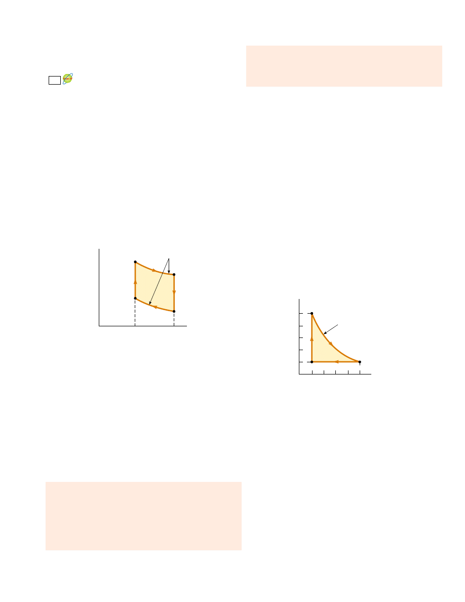
Problems
701
Carnot engine is
In 1816 Robert Stirling, a Scottish clergyman,
patented the Stirling engine, which has found a wide variety
of applications ever since. Fuel is burned externally to
warm one of the engine’s two cylinders. A fixed quantity of
inert gas moves cyclically between the cylinders, expanding
in the hot one and contracting in the cold one. Figure
P22.57 represents a model for its thermodynamic cycle.
Consider n mol of an ideal monatomic gas being taken
once through the cycle, consisting of two isothermal
processes at temperatures 3T
i
and T
i
and two constant-
volume processes. Determine, in terms of n, R, and T
i
,
(a) the net energy transferred by heat to the gas and
(b) the efficiency of the engine. A Stirling engine is easier
to manufacture than an internal combustion engine or a
turbine. It can run on burning garbage. It can run on the
energy of sunlight and produce no material exhaust.
57.
W
eng
!
mc(T
h
1/2
"
T
c
1/2
)
2
58.
An electric power plant has an overall efficiency of 15.0%.
The plant is to deliver 150 MW of power to a city, and its
turbines use coal as the fuel. The burning coal produces
steam that drives the turbines. This steam is then con-
densed to water at 25.0°C by passing it through cooling
coils in contact with river water. (a) How many metric tons
of coal does the plant consume each day (1 metric
ton ! 10
3
kg)? (b) What is the total cost of the fuel per
year if the delivered price is $8.00/metric ton? (c) If the
river water is delivered at 20.0°C, at what minimum rate
must it flow over the cooling coils in order that its temper-
ature not exceed 25.0°C? (Note: The heat of combustion of
coal is 33.0 kJ/g.)
59.
A power plant, having a Carnot efficiency, produces
1 000 MW of electrical power from turbines that take in
steam at 500 K and reject water at 300 K into a flowing river.
The water downstream is 6.00 K warmer due to the output of
the power plant. Determine the flow rate of the river.
60.
A power plant, having a Carnot efficiency, produces elec-
tric power ! from turbines that take in energy from steam
at temperature T
h
and discharge energy at temperature T
c
through a heat exchanger into a flowing river. The water
downstream is warmer by %T due to the output of the
power plant. Determine the flow rate of the river.
61.
An athlete whose mass is 70.0 kg drinks 16 oz (453.6 g) of
refrigerated water. The water is at a temperature of 35.0°F.
(a) Ignoring the temperature change of the body that re-
sults from the water intake (so that the body is regarded as
a reservoir always at 98.6°F), find the entropy increase of
the entire system. (b) What If ? Assume that the entire
body is cooled by the drink and that the average specific
heat of a person is equal to the specific heat of liquid
water. Ignoring any other energy transfers by heat and any
metabolic energy release, find the athlete’s temperature
after she drinks the cold water, given an initial body
temperature of 98.6°F. Under these assumptions, what is
the entropy increase of the entire system? Compare this
result with the one you obtained in part (a).
62.
A 1.00-mol sample of an ideal monatomic gas is taken
through the cycle shown in Figure P22.62. The process
A : B is a reversible isothermal expansion. Calculate
(a) the net work done by the gas, (b) the energy added to
the gas by heat, (c) the energy exhausted from the gas by
heat, and (d) the efficiency of the cycle.
63.
A biology laboratory is maintained at a constant tempera-
ture of 7.00°C by an air conditioner, which is vented to the
air outside. On a typical hot summer day the outside
temperature is 27.0°C and the air conditioning unit emits
energy to the outside at a rate of 10.0 kW. Model the unit
as having a coefficient of performance equal to 40.0% of
the coefficient of performance of an ideal Carnot device.
(a) At what rate does the air conditioner remove energy
from the laboratory? (b) Calculate the power required for
the work input. (c) Find the change in entropy produced
by the air conditioner in 1.00 h. (d) What If ? The
outside temperature increases to 32.0)C. Find the
fractional change in the coefficient of performance of the
air conditioner.
64.
A 1.00-mol sample of an ideal gas expands isothermally,
doubling in volume. (a) Show that the work it does in ex-
Isothermal
processes
P
V
V
i
2V
i
T
i
3T
i
Figure P22.57
5
Isothermal
process
1
10
50
V(liters)
B
C
A
P(atm)
Figure P22.62

702
C H A P T E R 2 2 • Heat Engines, Entropy, and the Second Law of Thermodynamics
panding is W ! RT ln 2. (b) Because the internal energy
E
int
of an ideal gas depends solely on its temperature, the
change in internal energy is zero during the expansion. It
follows from the first law that the energy input to the gas
by heat during the expansion is equal to the energy output
by work. Why does this conversion not violate the second
law?
A 1.00-mol sample of a monatomic ideal gas is taken
through the cycle shown in Figure P22.65. At point A, the
pressure, volume, and temperature are P
i
, V
i
, and T
i
,
respectively. In terms of R and T
i
, find (a) the total energy
entering the system by heat per cycle, (b) the total energy
leaving the system by heat per cycle, (c) the efficiency of
an engine operating in this cycle, and (d) the efficiency of
an engine operating in a Carnot cycle between the same
temperature extremes.
65.
An idealized diesel engine operates in a cycle known as the
air-standard diesel cycle, shown in Figure 22.14. Fuel is
sprayed into the cylinder at the point of maximum com-
pression, B. Combustion occurs during the expansion
B : C, which is modeled as an isobaric process. Show that
the efficiency of an engine operating in this idealized
diesel cycle is
70.
A 1.00-mol sample of an ideal gas (* ! 1.40) is carried
through the Carnot cycle described in Figure 22.11. At
point A, the pressure is 25.0 atm and the temperature is
600 K. At point C, the pressure is 1.00 atm and the temper-
ature is 400 K. (a) Determine the pressures and volumes at
points A, B, C, and D. (b) Calculate the net work done per
cycle. (c) Determine the efficiency of an engine operating
in this cycle.
71.
Suppose 1.00 kg of water at 10.0°C is mixed with 1.00 kg of
water at 30.0°C at constant pressure. When the mixture
has reached equilibrium, (a) what is the final tempera-
ture? (b) Take c
P
!
4.19 kJ/kg ( K for water and show that
the entropy of the system increases by
(c) Verify numerically that %S # 0. (d) Is the mixing an ir-
reversible process?
Answers to Quick Quizzes
22.1 (c). Equation 22.2 gives this result directly.
22.2 (b). The work represents one third of the input energy.
The remainder, two thirds, must be expelled to the cold
reservoir.
22.3 (d). The COP of 4.00 for the heat pump means that you
are receiving four times as much energy as the energy en-
tering by electrical transmission. With four times as much
energy per unit of energy from electricity, you need only
one fourth as much electricity.
22.4 C, B, A. Although all three engines operate over a 300-K
temperature difference, the efficiency depends on the
ratio of temperatures, not the difference.
22.5 One microstate—all four deuces.
22.6 Six microstates—club–diamond, club–heart, club–spade,
diamond–heart, diamond–spade, heart–spade. The
macrostate of two aces is more probable than that of four
deuces in Quick Quiz 22.5 because there are six times as
many microstates for this particular macrostate com-
pared to the macrostate of four deuces. Thus, in a hand
of poker, two of a kind is less valuable than four of a
kind.
22.7 (b). Because the process is reversible and adiabatic,
Q
r
!
0; therefore, %S ! 0.
%
S ! 4.19 ln
'
"
293
283
#
"
293
303
#
(
kJ/K
e ! 1 "
1
*
"
T
D
"
T
A
T
C
"
T
B
#
69.
P
B
C
A
D
V
V
i
2V
i
Q
4
Q
2
Q
1
Q
3
3P
i
2P
i
P
i
Figure P22.65
66.
A sample consisting of n mol of an ideal gas undergoes a
reversible isobaric expansion from volume V
i
to volume
3V
i
. Find the change in entropy of the gas by calculating
where dQ ! nC
P
dT.
A system consisting of n mol of an ideal gas undergoes two
reversible processes. It starts with pressure P
i
and volume
V
i
, expands isothermally, and then contracts adiabatically
to reach a final state with pressure P
i
and volume 3V
i
.
(a) Find its change in entropy in the isothermal process.
The entropy does not change in the adiabatic process.
(b) What If ? Explain why the answer to part (a) must be
the same as the answer to Problem 66.
68. Suppose you are working in a patent office, and an inven-
tor comes to you with the claim that her heat engine,
which employs water as a working substance, has a ther-
modynamic efficiency of 0.61. She explains that it oper-
ates between energy reservoirs at 4°C and 0°C. It is a very
complicated device, with many pistons, gears, and pul-
leys, and the cycle involves freezing and melting. Does
her claim that e ! 0.61 warrant serious consideration?
Explain.
67.
%
f
i
dQ /T

22.8 (a). From the first law of thermodynamics, for these two
reversible processes, Q
r
! %
E
int
"
W. During the con-
stant-volume process, W ! 0, while the work W is
nonzero and negative during the constant-pressure
expansion. Thus, Q
r
is larger for the constant-pressure
process, leading to a larger value for the change in
entropy. In terms of entropy as disorder, during the
constant-pressure process, the gas must expand. The
increase in volume results in more ways of locating the
molecules of the gas in a container, resulting in a larger
increase in entropy.
22.9 False. The determining factor for the entropy change is
Q
r
, not Q. If the adiabatic process is not reversible, the
entropy change is not necessarily zero because a re-
versible path between the same initial and final states may
involve energy transfer by heat.
Problems
703
Wyszukiwarka
Podobne podstrony:
Lieb, Yngvason Physics and mathematics of the 2nd law of thermodynamics (PR310, 1999)(96s)
Волощук Medieval Slovakia and Croatia as the second homeland of nobility and peoples from the Rus’ i
Today s View of the Third Reich and the Second World War in German Historiographical Discourse
Affirmative Action and the Legislative History of the Fourteenth Amendment
Oakeley, H D Epistemology And The Logical Syntax Of Language
Zizek And The Colonial Model of Religion
Botox, Migraine, and the American Academy of Neurology
The police exception and the domestic?use law
Fred Saberhagen Swords 2 The Second Book of Swords
new media and the permanent crisis of aura j d bolter et al
Bechara, Damasio Investment behaviour and the negative side of emotion
Death of a Salesman and The Price Analysis of Ideals
The Universal Law of Attraction
Fred Saberhagen Swords 02 The Second Book of Swords
Oscar Wilde, The Picture of Dorian Gray, and the (Un)Death of the Author
Isaac Asimov Lucky Starr 03 And the Big Sun of Mercury
więcej podobnych podstron