
CREAD CWRITE R4.1 07.02.00 en
1 of 42
SOFTWARE
KR C...
CREAD CWRITE
Release 4.1

2 of 42
CREAD CWRITE R4.1 07.02.00 en
e
Copyright
KUKA Roboter GmbH
This documentation or excerpts therefrom may not be reproduced or disclosed to third parties without the express permission of the publishers.
Other functions not described in this documentation may be operable in the controller. The user has no claim to these functions, however, in
the case of a replacement or service work.
We have checked the content of this documentation for conformity with the hardware and software described. Nevertheless, discrepancies
cannot be precluded, for which reason we are not able to guarantee total conformity. The information in this documentation is checked on a
regular basis, however, and necessary corrections will be incorporated in subsequent editions.
Subject to technical alterations without an effect on the function.
PD Interleaf

3 of 42
CREAD CWRITE R4.1 07.02.00 en
Contents
1
General
5
. . . . . . . . . . . . . . . . . . . . . . . . . . . . . . . . . . . . . . . . . . . . . . . . . . . . . . . . .
1.1
Areas of application
5
. . . . . . . . . . . . . . . . . . . . . . . . . . . . . . . . . . . . . . . . . . . . . . . . . . . . . . . . . . . .
1.2
Operation
5
. . . . . . . . . . . . . . . . . . . . . . . . . . . . . . . . . . . . . . . . . . . . . . . . . . . . . . . . . . . . . . . . . . . . .
1.3
Hardware prerequisites
5
. . . . . . . . . . . . . . . . . . . . . . . . . . . . . . . . . . . . . . . . . . . . . . . . . . . . . . . . .
1.4
Application in SUB and SRC programs
6
. . . . . . . . . . . . . . . . . . . . . . . . . . . . . . . . . . . . . . . . . . . .
1.5
Overview of commands
6
. . . . . . . . . . . . . . . . . . . . . . . . . . . . . . . . . . . . . . . . . . . . . . . . . . . . . . . . .
1.5.1
CHANNEL
6
. . . . . . . . . . . . . . . . . . . . . . . . . . . . . . . . . . . . . . . . . . . . . . . . . . . . . . . . . . . . . . . . . . . .
1.5.2
COPEN
6
. . . . . . . . . . . . . . . . . . . . . . . . . . . . . . . . . . . . . . . . . . . . . . . . . . . . . . . . . . . . . . . . . . . . . .
1.5.3
CREAD
6
. . . . . . . . . . . . . . . . . . . . . . . . . . . . . . . . . . . . . . . . . . . . . . . . . . . . . . . . . . . . . . . . . . . . . . .
1.5.4
CWRITE
6
. . . . . . . . . . . . . . . . . . . . . . . . . . . . . . . . . . . . . . . . . . . . . . . . . . . . . . . . . . . . . . . . . . . . . .
1.5.5
CCLOSE
6
. . . . . . . . . . . . . . . . . . . . . . . . . . . . . . . . . . . . . . . . . . . . . . . . . . . . . . . . . . . . . . . . . . . . .
1.5.6
SREAD
6
. . . . . . . . . . . . . . . . . . . . . . . . . . . . . . . . . . . . . . . . . . . . . . . . . . . . . . . . . . . . . . . . . . . . . . .
1.5.7
SWRITE
6
. . . . . . . . . . . . . . . . . . . . . . . . . . . . . . . . . . . . . . . . . . . . . . . . . . . . . . . . . . . . . . . . . . . . . .
1.6
Typographical conventions
6
. . . . . . . . . . . . . . . . . . . . . . . . . . . . . . . . . . . . . . . . . . . . . . . . . . . . . .
2
Configuration
7
. . . . . . . . . . . . . . . . . . . . . . . . . . . . . . . . . . . . . . . . . . . . . . . . . . . .
2.1
Configuration of the serial interface
7
. . . . . . . . . . . . . . . . . . . . . . . . . . . . . . . . . . . . . . . . . . . . . . .
2.1.1
Assignment of a serial channel to the KR C2
7
. . . . . . . . . . . . . . . . . . . . . . . . . . . . . . . . . . . . . . .
2.1.1.1 Interface definitions in the file SERIAL.INI
7
. . . . . . . . . . . . . . . . . . . . . . . . . . . . . . . . . . . . . . . . .
2.2
State and mode information
9
. . . . . . . . . . . . . . . . . . . . . . . . . . . . . . . . . . . . . . . . . . . . . . . . . . . . .
3
Commands
11
. . . . . . . . . . . . . . . . . . . . . . . . . . . . . . . . . . . . . . . . . . . . . . . . . . . . . .
3.1
CHANNEL
11
. . . . . . . . . . . . . . . . . . . . . . . . . . . . . . . . . . . . . . . . . . . . . . . . . . . . . . . . . . . . . . . . . . . .
3.1.1
Syntax
11
. . . . . . . . . . . . . . . . . . . . . . . . . . . . . . . . . . . . . . . . . . . . . . . . . . . . . . . . . . . . . . . . . . . . . . .
3.1.2
Definition, description
11
. . . . . . . . . . . . . . . . . . . . . . . . . . . . . . . . . . . . . . . . . . . . . . . . . . . . . . . . . . .
3.1.3
Example: Assignment of a channel name to a physical channel
11
. . . . . . . . . . . . . . . . . . . . . .
3.2
COPEN
12
. . . . . . . . . . . . . . . . . . . . . . . . . . . . . . . . . . . . . . . . . . . . . . . . . . . . . . . . . . . . . . . . . . . . . .
3.2.1
Syntax
12
. . . . . . . . . . . . . . . . . . . . . . . . . . . . . . . . . . . . . . . . . . . . . . . . . . . . . . . . . . . . . . . . . . . . . . .
3.2.2
Definition, description
12
. . . . . . . . . . . . . . . . . . . . . . . . . . . . . . . . . . . . . . . . . . . . . . . . . . . . . . . . . . .
3.2.3
Example
12
. . . . . . . . . . . . . . . . . . . . . . . . . . . . . . . . . . . . . . . . . . . . . . . . . . . . . . . . . . . . . . . . . . . . . .
3.3
CREAD
13
. . . . . . . . . . . . . . . . . . . . . . . . . . . . . . . . . . . . . . . . . . . . . . . . . . . . . . . . . . . . . . . . . . . . . . .
3.3.1
Syntax
13
. . . . . . . . . . . . . . . . . . . . . . . . . . . . . . . . . . . . . . . . . . . . . . . . . . . . . . . . . . . . . . . . . . . . . . .
3.3.2
Definition, description
14
. . . . . . . . . . . . . . . . . . . . . . . . . . . . . . . . . . . . . . . . . . . . . . . . . . . . . . . . . . .
3.4
CWRITE
18
. . . . . . . . . . . . . . . . . . . . . . . . . . . . . . . . . . . . . . . . . . . . . . . . . . . . . . . . . . . . . . . . . . . . . .
3.4.1
Syntax
18
. . . . . . . . . . . . . . . . . . . . . . . . . . . . . . . . . . . . . . . . . . . . . . . . . . . . . . . . . . . . . . . . . . . . . . .
3.4.2
Definition, description
19
. . . . . . . . . . . . . . . . . . . . . . . . . . . . . . . . . . . . . . . . . . . . . . . . . . . . . . . . . . .
3.4.3
Examples
22
. . . . . . . . . . . . . . . . . . . . . . . . . . . . . . . . . . . . . . . . . . . . . . . . . . . . . . . . . . . . . . . . . . . . .
3.4.3.1 Conversion of an integer value into decimal and hexadecimal notation
22
. . . . . . . . . . . . . . . .
3.4.3.2 Writing an integer value in binary notation
22
. . . . . . . . . . . . . . . . . . . . . . . . . . . . . . . . . . . . . . . . .
3.4.3.3 Writing of the first 5 array elements of an array
22
. . . . . . . . . . . . . . . . . . . . . . . . . . . . . . . . . . . . .
3.4.3.4 Output of values of all array elements of an array
22
. . . . . . . . . . . . . . . . . . . . . . . . . . . . . . . . . .
3.4.3.5 Output of the first initialized array elements
22
. . . . . . . . . . . . . . . . . . . . . . . . . . . . . . . . . . . . . . . .
3.4.3.6 Writing of the first 50 elements of a character string
22
. . . . . . . . . . . . . . . . . . . . . . . . . . . . . . . .
3.4.3.7 Conversion of the ENUM constants into ASCII format
23
. . . . . . . . . . . . . . . . . . . . . . . . . . . . . . .

CREAD CWRITE
4 of 42
CREAD CWRITE R4.1 07.02.00 en
3.4.3.8 Writing of two real values with text
23
. . . . . . . . . . . . . . . . . . . . . . . . . . . . . . . . . . . . . . . . . . . . . . .
3.4.3.9 Writing to the command channel
23
. . . . . . . . . . . . . . . . . . . . . . . . . . . . . . . . . . . . . . . . . . . . . . . . .
3.5
CCLOSE
24
. . . . . . . . . . . . . . . . . . . . . . . . . . . . . . . . . . . . . . . . . . . . . . . . . . . . . . . . . . . . . . . . . . . . .
3.5.1
Syntax
24
. . . . . . . . . . . . . . . . . . . . . . . . . . . . . . . . . . . . . . . . . . . . . . . . . . . . . . . . . . . . . . . . . . . . . . .
3.5.2
Definition, description
24
. . . . . . . . . . . . . . . . . . . . . . . . . . . . . . . . . . . . . . . . . . . . . . . . . . . . . . . . . . .
3.5.3
Example
24
. . . . . . . . . . . . . . . . . . . . . . . . . . . . . . . . . . . . . . . . . . . . . . . . . . . . . . . . . . . . . . . . . . . . . .
3.6
SREAD
25
. . . . . . . . . . . . . . . . . . . . . . . . . . . . . . . . . . . . . . . . . . . . . . . . . . . . . . . . . . . . . . . . . . . . . . .
3.6.1
Syntax
25
. . . . . . . . . . . . . . . . . . . . . . . . . . . . . . . . . . . . . . . . . . . . . . . . . . . . . . . . . . . . . . . . . . . . . . .
3.6.2
Definition, description
26
. . . . . . . . . . . . . . . . . . . . . . . . . . . . . . . . . . . . . . . . . . . . . . . . . . . . . . . . . . .
3.6.3
Example
26
. . . . . . . . . . . . . . . . . . . . . . . . . . . . . . . . . . . . . . . . . . . . . . . . . . . . . . . . . . . . . . . . . . . . . .
3.7
SWRITE
27
. . . . . . . . . . . . . . . . . . . . . . . . . . . . . . . . . . . . . . . . . . . . . . . . . . . . . . . . . . . . . . . . . . . . . .
3.7.1
Syntax
27
. . . . . . . . . . . . . . . . . . . . . . . . . . . . . . . . . . . . . . . . . . . . . . . . . . . . . . . . . . . . . . . . . . . . . . .
3.7.2
Definition, description
27
. . . . . . . . . . . . . . . . . . . . . . . . . . . . . . . . . . . . . . . . . . . . . . . . . . . . . . . . . . .
3.7.3
Examples
29
. . . . . . . . . . . . . . . . . . . . . . . . . . . . . . . . . . . . . . . . . . . . . . . . . . . . . . . . . . . . . . . . . . . . .
3.7.3.1 Copy the content of the variable HUGO into the variable BERTA
29
. . . . . . . . . . . . . . . . . . . . .
3.7.3.2 Use of formatting characters
29
. . . . . . . . . . . . . . . . . . . . . . . . . . . . . . . . . . . . . . . . . . . . . . . . . . . . .
3.8
Diagnosis
30
. . . . . . . . . . . . . . . . . . . . . . . . . . . . . . . . . . . . . . . . . . . . . . . . . . . . . . . . . . . . . . . . . . . . .
3.9
Example program for using COPEN, CWRITE, CREAD and CCLOSE
31
. . . . . . . . . . . . . . . .
4
Procedure 3964R and Xon/Xoff protocol
33
. . . . . . . . . . . . . . . . . . . . . . . . . . .
4.1
Procedure 3964R
33
. . . . . . . . . . . . . . . . . . . . . . . . . . . . . . . . . . . . . . . . . . . . . . . . . . . . . . . . . . . . . .
4.1.1
Procedure data
33
. . . . . . . . . . . . . . . . . . . . . . . . . . . . . . . . . . . . . . . . . . . . . . . . . . . . . . . . . . . . . . . .
4.1.1.1 Bit sequence
33
. . . . . . . . . . . . . . . . . . . . . . . . . . . . . . . . . . . . . . . . . . . . . . . . . . . . . . . . . . . . . . . . . .
4.1.1.2 Procedure parameters
34
. . . . . . . . . . . . . . . . . . . . . . . . . . . . . . . . . . . . . . . . . . . . . . . . . . . . . . . . . .
4.1.1.3 Variable specifications for procedure 3964R
34
. . . . . . . . . . . . . . . . . . . . . . . . . . . . . . . . . . . . . . .
4.1.1.4 Fixed specifications for procedure 3964R
34
. . . . . . . . . . . . . . . . . . . . . . . . . . . . . . . . . . . . . . . . .
4.1.1.5 Procedure 3964R settings in the file SERIAL.INI
35
. . . . . . . . . . . . . . . . . . . . . . . . . . . . . . . . . . .
4.1.2
Transmission with procedure 3964R
35
. . . . . . . . . . . . . . . . . . . . . . . . . . . . . . . . . . . . . . . . . . . . . .
4.1.2.1 Establishing the connection
35
. . . . . . . . . . . . . . . . . . . . . . . . . . . . . . . . . . . . . . . . . . . . . . . . . . . . .
4.1.2.2 Sending information
35
. . . . . . . . . . . . . . . . . . . . . . . . . . . . . . . . . . . . . . . . . . . . . . . . . . . . . . . . . . . .
4.1.2.3 KR C2 sends data
36
. . . . . . . . . . . . . . . . . . . . . . . . . . . . . . . . . . . . . . . . . . . . . . . . . . . . . . . . . . . . .
4.1.3
Receiving with procedure 3964R
36
. . . . . . . . . . . . . . . . . . . . . . . . . . . . . . . . . . . . . . . . . . . . . . . . .
4.1.3.1 Rest condition
36
. . . . . . . . . . . . . . . . . . . . . . . . . . . . . . . . . . . . . . . . . . . . . . . . . . . . . . . . . . . . . . . . .
4.1.3.2 Receiving information
36
. . . . . . . . . . . . . . . . . . . . . . . . . . . . . . . . . . . . . . . . . . . . . . . . . . . . . . . . . . .
4.1.3.3 KR C2 receives data
37
. . . . . . . . . . . . . . . . . . . . . . . . . . . . . . . . . . . . . . . . . . . . . . . . . . . . . . . . . . .
4.1.4
Initialization conflicts
37
. . . . . . . . . . . . . . . . . . . . . . . . . . . . . . . . . . . . . . . . . . . . . . . . . . . . . . . . . . .
4.2
Xon/Xoff protocol
38
. . . . . . . . . . . . . . . . . . . . . . . . . . . . . . . . . . . . . . . . . . . . . . . . . . . . . . . . . . . . . .
5
Serial interfaces
39
. . . . . . . . . . . . . . . . . . . . . . . . . . . . . . . . . . . . . . . . . . . . . . . . .
5.1
Sub--D connector, 9 pins
39
. . . . . . . . . . . . . . . . . . . . . . . . . . . . . . . . . . . . . . . . . . . . . . . . . . . . . . . .
5.2
Connector pin allocation for Sub--D, 9 pins
40
. . . . . . . . . . . . . . . . . . . . . . . . . . . . . . . . . . . . . . . .
6
Appendix
41
. . . . . . . . . . . . . . . . . . . . . . . . . . . . . . . . . . . . . . . . . . . . . . . . . . . . . . . .
6.1
ASCII character map
41
. . . . . . . . . . . . . . . . . . . . . . . . . . . . . . . . . . . . . . . . . . . . . . . . . . . . . . . . . . .
1
General
5 of 42
CREAD CWRITE R4.1 07.02.00 en
1
General
“CREAD / CWRITE” describes the logical combination of symbolic interface names with
predefined signal variables for serial interfaces as well as the declaration of signal names
for input and output channels (CHANNEL), and how to open input and output channels
(COPEN), read data from open channels (CREAD), write data to channels (CWRITE) and
close channels (CCLOSE).
1.1
Areas of application
About 95% of CREAD/CWRITE applications are in the field of serial sensor systems.
Examples include vision systems, barcode scanners and MeasureTech.
Command channel applications, e.g. automatic system start with CELL.SRC, account for the
other 5%.
1.2
Operation
In order to be able to access a channel, it must be declared in the “CHANNEL” declaration.
In the KR C2, the three serial interfaces COM1, COM2 and COM3 are declared by default
as SER_1, SER_2 and SER_3 in the file “$CUSTOM.DAT”.
Each channel must be opened by means of the “COPEN” statement before it can be used.
The “CREAD” statement can be used to read the channel, while the “CWRITE” statement
is used to write to the channel.
The channel is closed with the “CCLOSE” statement.
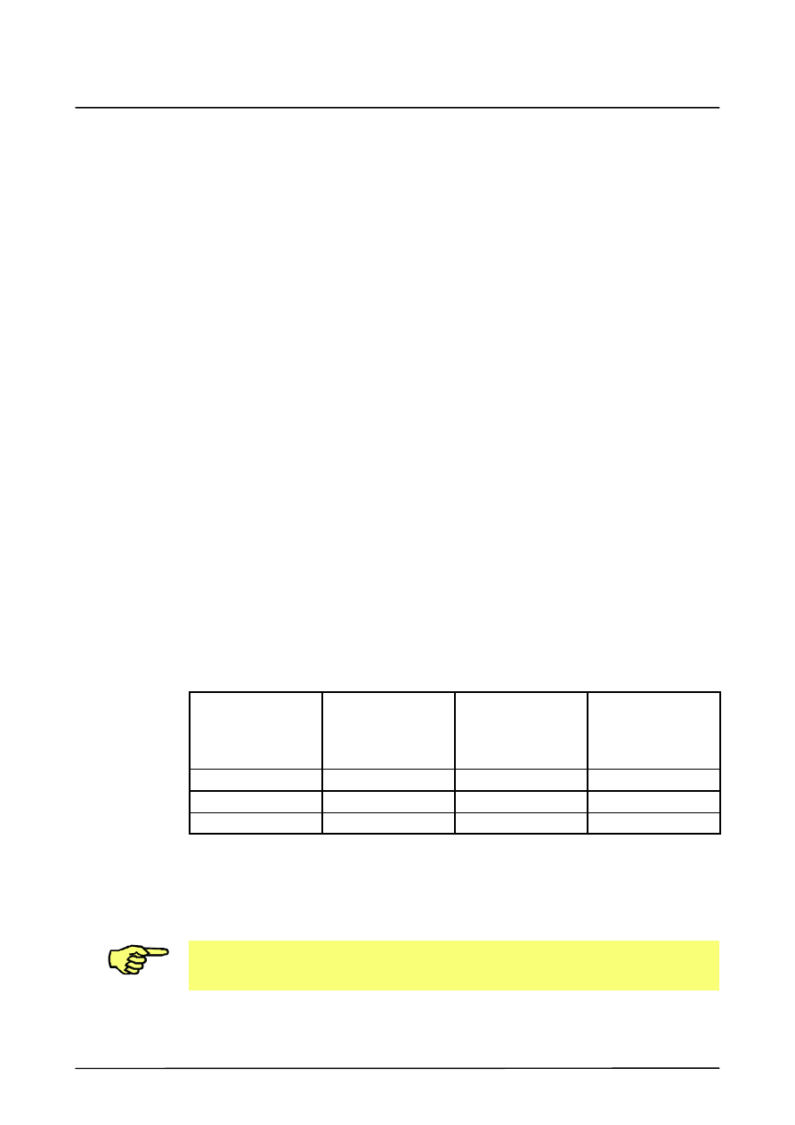
1.3
Hardware prerequisites
Depending on the type of controller and the motherboard installed, the following COM ports
are available for the serial communication of the robot (VxWorks):
KR C1
KR C2
with motherboard
SuperMicro 370SBA
KR C2
with motherboard
Soyo SY--7VBA
133u
COM1
X
--
--
COM2
X
(X)
--
COM3
--
X
X
X
Port can be configured for robots.
--
Port cannot be configured for robots.
(X)
Port can be configured for robots if two ports are required simultaneously.
In the case of applications with the KR C2 controller, it may be necessary to deactivate the
mouse drivers via the Windows Control Panel, as the serial data exchange may not run
smoothly otherwise.

CREAD CWRITE
6 of 42
CREAD CWRITE R4.1 07.02.00 en
1.4
Application in SUB and SRC programs
The COPEN, CREAD, CWRITE and CCLOSE statements can be used in both SRC and
SUB programs. If a channel has been opened in an SRC program, it must be closed again
before it can be used in a SUB program.
The same applies inversely to channels that have been opened in a SUB program.
1.5
Overview of commands
1.5.1
CHANNEL
Declaration of signal names for input and output channels.
1.5.2
COPEN
Opening an input/output channel.
1.5.3
CREAD
Reading of data from channels.
1.5.4
CWRITE
Writing of data to channels.
1.5.5
CCLOSE
Closing of channels.
1.5.6
SREAD
Reading of character strings from a variable.
1.5.7
SWRITE
Writing of data to a variable.
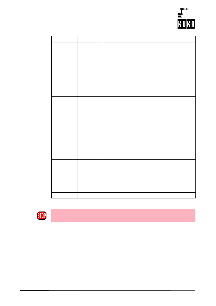
1.6
Typographical conventions
Example
Explanation
DEFTP
Static syntax elements and keywords are printed as
upper--case characters in bold type. They must be
used without modification.
Name
Terms printed in italics must be replaced by
user--specific information.
á ñ
Elements in angle brackets are optional.
|
The OR sign is used to separate mutually exclusive
options.

2
Configuration
7 of 42
CREAD CWRITE R4.1 07.02.00 en
2
Configuration
2.1
Configuration of the serial interface
2.1.1
Assignment of a serial channel to the KR C2
By default, the serial interfaces are assigned to Windows. In order to be able to use them
from the KR C2, they must be assigned to the KRC operating system VxWorks in the file
“HW_INF.INI” (in the directory “C:\KRC\Roboter\INIT”).
The required COMx port can be enabled using the Enum constants ENABLE and DISABLE:
ENABLE: the interface can be accessed by the KRC kernel system VxWorks
DISABLE: the interface can be accessed by Windows
Example: COM3 is to be reserved for the KR C2:
[SERIAL]
;ENABLE: COM is accessible by vxWorks
;DISABLE: COM is accessible by Win95
COM1=DISABLE
;[ENABLE, DISABLE]
COM2=DISABLE
;[ENABLE, DISABLE]
COM3=ENABLE
;[ENABLE, DISABLE] useable only for VxWorks
2.1.1.1 Interface definitions in the file SERIAL.INI
The serial interfaces are defined in the file “SERIAL.INI” (in the directory
“C:\KRC\Roboter\INIT”).
; SERIAL.INI
; Configuration of the serial ports and their procedures
;
; Lindemann 15.02.99
R12-S4: Protocol XON/XOFF implemented
; Lindemann 19.03.99
R12-T9: Receive buffer expanded to 2048
characters
; Lindemann 27.09.00
R12-T9: COM3/4 implemented
[COM1]
BAUD=9600
CHAR_LEN=8
; 7,8
STOP_BIT=1
; 1,2
at time not changeable
PARITY=2
; EVEN=2, ODD=1, NONE=0
PROC=1
; 3964R=1, SRVT=2, WTC=3, XONXOFF=4
[COM2]
BAUD=9600
CHAR_LEN=8
; 7,8
STOP_BIT=1
; 1,2
at time not changeable
PARITY=2
; EVEN=2, ODD=1, NONE=0
PROC=1
; 3964R=1, SRVT=2, WTC=3, XONXOFF=4
[COM3]
BAUD=9600
CHAR_LEN=8
; 7,8
STOP_BIT=1
; 1,2
at time not changeable
PARITY=2
; EVEN=2, ODD=1, NONE=0
PROC=1
; 3964R=1, SRVT=2, WTC=3, XONXOFF=4

CREAD CWRITE
8 of 42
CREAD CWRITE R4.1 07.02.00 en
[3964R]
CHAR_TIMEOUT=500
; msec
QUITT_TIMEOUT=500
; msec
TRANS_TIMEOUT=2000 ; msec
MAX_TX_BUFFER=2
; 1..5
MAX_RX_BUFFER=10
; 1..20
SIZE_RX_BUFFER=100
; 1..2048
PROTOCOL_PRIOR=1
; HIGH=1, LOW=0
[SRVT]
CHAR_TIMEOUT=200
; msec
MAX_TX_BUFFER=2
; 1..5
MAX_RX_BUFFER=2
; 1..20
SIZE_RX_BUFFER=100
; 1..2048
[WTC]
CHAR_TIMEOUT=200
; msec
MAX_TX_BUFFER=2
; 1..5
MAX_RX_BUFFER=2
; 1..20
SIZE_RX_BUFFER=50
; 1..2048
[XONXOFF]
CHAR_TIMEOUT=50
; msec
Timeout after last received character
; to recognize the end of telegram
MAX_TX_BUFFER=2
; 1..5
MAX_RX_BUFFER=2
; 1..20
SIZE_RX_BUFFER=100
; 1..2048 longest expected telegram length
;+ 15 characters
XON_VAL=17
; 0..255
XON
character (decimal)
XOFF_VAL=19
; 0..255
XOFF character (decimal)
; if XON_VAL=0 and XOFF_VAL=0 then XON/XOFF
; protocol
; is disabled (pure communication)
[TEST]
;testprint (Rx/Tx-telegrams) on telnet if value > 0
TESTPRINT=0
[END SECTION]
The structure variables “$PSER_X” in the system file $CUSTOM.DAT are not evaluated.
Once modifications have been made in the files HW_INF.INI or SERIAL.INI, the controller
must be rebooted by means of a cold start in order for the changes to take effect.

2
Configuration (continued)
9 of 42
CREAD CWRITE R4.1 07.02.00 en
2.2
State and mode information
The state information is returned in a variable of the predefined structure type “STATE_T”.
“STATE_T” has the following definition:
STRUC STATE_T CMD_STAT RET1, INT HITS, INT LENGTH
“CMD_STAT” is a predefined enumeration type of the following form:
ENUM CMD_STAT CMD_OK, CMD_TIMEOUT, DATA_OK, DATA_BLK, DATA_END,
CMD_ABORT, CMD_REJ, CMD_PART, CMD_SYN, FMT_ERR
The modes that can be used with the statements “CREAD” and “CWRITE” are made
available as a predefined enumeration type:
ENUM MODUS_T SYNC, ASYNC, ABS, COND, SEQ

CREAD CWRITE
10 of 42
CREAD CWRITE R4.1 07.02.00 en

3
Commands
11 of 42
CREAD CWRITE R4.1 07.02.00 en
3
Commands
3.1
CHANNEL
Declaration of signal names for input and output channels.
3.1.1
Syntax
CHANNEL :Channel_Name:Interface_Name Structure_Variable
Argument
Type
Explanation
Channel_Name
Any symbolic name
Interface_Name
Predefined signal variable
SER_1
serial interface 1
SER_2
serial interface 2
SER_3
serial interface 3
Structure_Variable
System--dependent structure variable
$PSER_1, $PSER_2 or $PSER_3 specify-
ing the protocol. Evaluation is not carried
out.
3.1.2
Definition, description
The robot controller contains two classes of interface:
G
simple process interfaces -- signals.
G
logic interfaces -- channels.
All of the interfaces are addressed using symbolic names. The specific interface names
(symbolic names) are logically combined with the predefined signal variables for channels
by means of the CHANNEL declaration.
The predefined signal variables for channels are
G
SER_1
G
SER_2
G
SER_3
for the serial interfaces, and
G
$CMD (e.g. “RUN....”)
for the command interpreter.
They are predefined in the file “$CUSTOM.DAT” in the directory
“C:\KRC\ROBOTER\KRC\STEU\MADA”.
3.1.3
Example:
Assignment of a channel name to a physical channel
With the “CHANNEL” statement:
Channel name
SER_3
is assigned to
physical channel
SER_3
CHANNEL :SER_3 :SER_3 $PSER_3
CREAD CWRITE
12 of 42
CREAD CWRITE R4.1 07.02.00 en
3.2
COPEN
Opening an input/output channel.
3.2.1
Syntax
COPEN (:Channel_Name, Handle)
Argument
Type
Explanation
Channel_Name
Channel name declared in the “CHANNEL”
statement.
Handle
INT
Open interface number feedback signal: 1,
2 or 3 (or 0 in the event of an error).
3.2.2
Definition, description
Input/output channels that have previously been declared with the CHANNEL statement can
be opened using the “COPEN” statement – which may be included in programs at control
or robot levels.
The “Handle” variable identifies the relevant channel for all of the following accesses. If the
system refuses to open a channel, a 0 is returned.
The predefined system variable “$CMD” is available as a handle for execution of commands,
which are generally open.
3.2.3
Example
Opening of a channel with the declared channel name “SER_3” and the handle
“HANDLE”.
INT HANDLE
...
COPEN(:SER_3,HANDLE)

3
Commands (continued)
13 of 42
CREAD CWRITE R4.1 07.02.00 en
3.3
CREAD
Reading of data from channels.
3.3.1
Syntax
CREAD
(Handle, State, Mode, Timeout, Offset, Format,
Var1
á
, ..., VarN
ñ
)
Argument
Type
Explanation
Handle
INT
The Handle variable transferred by “COPEN”.
Note: the variable “$CMD” will be rejected!
State
STATE_T
“CMD_STAT” is an enumeration type which is the first
component of the “State” variable of the structure type
“STATE_T”. “CMD_STAT” can have the following
values which are relevant for “CREAD”:
CMD_OK
Command successfully executed;
no data available in #COND mode.
CMD_TIMEOUT Reading aborted in “ABS” mode due to
the defined time limit being exceeded.
DATA_OK
A data block has been received from
the channel. All of the data have been
assigned to the variables in accordance
with the format description. However, it
is not necessary for all the variables to
have been described (see also the
State variable “HITS” below).
DATA_BLK
Data have been read but further data
which can be read using the mode
“SEQ” are ready.
DATA_END
Data have been read. The data block
has been completely read.
CMD_ABORT
Reading has been aborted, e.g. due to
an error message from the channel or
to a fatal error during read--out of the
data. If the format specification and the
variable type do not agree, reading is
aborted not with CMD_ABORT but with
DATA_BLK.
FMT_ERR
Incorrect format specification or non--
corresponding variable.
Other components of the State variable that are impor-
tant for CREAD:
HITS
Number of correctly read formats.
LENGTH
Length of the “%s” or “%r” format that
occurs first in the format. The lengths
of all following “%s” or “%r” formats are
not determined. If necessary, use
several “CREAD” statements.
CREAD CWRITE
14 of 42
CREAD CWRITE R4.1 07.02.00 en
Argument
Type
Explanation
Mode
MODUS_T
“MODUS_T” is an enumeration type that can have the
following values that are relevant for “CREAD”:
ABS
Active reading of the channel.
The function waits until the channel makes a
data block available or until waiting is aborted
by Timeout.
COND
Immediate reading when data are received.
SEQ
Completion of the reading of a data block from
Bytes Offset onwards that has previously been
requested using “ABS” or “COND” or returned
to “CWRITE” as a reply and which has not yet
been completely read out.
Timeout
REAL
The parameter “Timeout” can be used to specify a time
in seconds, after which the wait for a data block is
aborted. A Timeout with the value 0.0 corresponds to
an endless wait.
A value over 60 or negative values are rejected. A
system--related inaccuracy is inherent in the wait time.
Offset
INT
The variable “Offset” is used to specify the number of
bytes in the data that have been received after which
the system is to start reading. If reading is to start from
the beginning, Offset must be set to 0 (zero).
After a “CREAD” statement that does not assign all of
the data received to program variables, Offset specifies
the number of characters that have been assigned so
far.
Format
CHAR[ ]
The variable “Format” of the type “CHAR[ ]” (Textstring)
contains the format of the text that is to be generated.
The number of format specifications per call is limited
to 10.
The structure of the variable largely corresponds to the
format string of the function “FPRINTF” of the “C”
programming language.
VarX
The variables corresponding to “Format”.
If a Handle that does not come from a “COPEN” statement of the process is transferred
in the “CREAD” statement or if the channel has already been closed again, the
acknowledgement message “INVALID HANDLE” is displayed.
3.3.2
Definition, description
The “CREAD” statement is used for reading data from open channels. Two cases are
distinguished here:
G
Active reading
The program requests an input via a channel. The channel drivers set an input request
and return the data that are received to the CREAD statement as a result.
G
Passive reading
Another partner has written data to a channel without being requested to and expects
the data to be collected. A predefined variable is made available for each of the
channels “SER_1”, “SER_2” and “SER_3”.

3
Commands (continued)
15 of 42
CREAD CWRITE R4.1 07.02.00 en
INT $DATA_SER1
INT $DATA_SER2 and
INT $DATA_SER3
There are also differences in the way that the system waits for the feedback signal of a read
request. The “CREAD” statement can wait absolutely or conditionally.
--
Absolutely means that the system waits until the channel provides the data of the
type requested.
--
In the case of conditional waiting, the system checks whether data are available.
By using the feedback signal, it can be determined whether the read statement was
successful or not. The relevant procedure is defined by the parameter “Mode”.
The conversion specification for the Format variable has the following structure:
“%
á
W
ñ
U”
For arrays and type r, the following applies:
“%
á
W
á
.Z
ñ ñ
U”
The following definitions apply here:
W
Specification of the maximum number of characters to be read.
Z
Only for arrays and type r: number of array elements to be written.
U
Specification of the type to be written. The following are permissible: c, d, e, f, g, i, s,
x and r in accordance with the table below.
The system cannot distinguish between upper and lower--case letters.
The format specification and data type are checked in accordance with the following table
at run time:
Format specification
Permissi-
ble data
type
%d
%i
%x
%f
%e
%g
%c
%s
%1r
(3)
%1.
á
Z
ñ
r
%2r
(3)
%2.
á
Z
ñ
r
%4r
(3)
%4.
á
Z
ñ
r
(4)
%r
(3)
%.
á
Z
ñ
r
(SIGNAL)
INT
X
--
X
--
X
--
X
--
X
--
X
--
INT array
--
--
--
--
--
X
--
X
--
X
X
X
REAL
X
X
--
--
--
--
--
--
X
--
X
--
REAL
array
--
--
--
--
--
--
--
--
--
X
X
X
(Signal)
BOOL (1)
X
--
X
--
X
--
X
--
X
--
X
--
BOOL
array
--
--
--
--
--
X
--
X
--
X
X
X
ENUM (2)
X
--
X
--
X
--
X
--
X
--
X
--
ENUM
array
--
--
--
--
--
X
--
X
--
X
X
X
CHAR
X
--
X
--
X
--
--
--
--
--
X
--
CHAR
array
--
--
--
X
--
X
--
--
--
--
X
X

CREAD CWRITE
16 of 42
CREAD CWRITE R4.1 07.02.00 en
Remarks
(1) Every value that is not equal to 0 (zero) is converted to TRUE
(2) The system checks whether the value is a permissible ENUM value. If it is not, reading
is aborted. The value of the first Enum constant is 1.
(3) If there are not enough data available to satisfy the requirements of the format (e.g.
%2.5r, but only 7 bytes are present), nothing is read for this format and the CREAD
statement is aborted. The ignored data are, however, still ready for reading.
(4) Only as many bytes as can fit into the variable are read. The rest are still ready for
reading. If the array is actually big enough but the number of available bytes is not a
multiple of the size of an array element, the redundant bytes for the following format or
for the next CREAD statement are left for reading.
A message that is not completely read can be read further by the following “CREAD” calls.
The number of bytes of the “%s” or “%r” format specified first in the format string that have
actually been read is returned in the State variable.
All of the other lengths are not determined. It is therefore advisable to use “%s” and “%r”
formats only once in a format string and to repeat the “CREAD” call.
If the “%s” or “%r” format is not among the formats that have been successfully read (see
“HITS” of the State variable), the value of “LENGTH” is not changed by the statement.

3
Commands (continued)
17 of 42
CREAD CWRITE R4.1 07.02.00 en
The specification of other modes or of non--initialized variables causes an error to be
detected in the variable “State”. If reading with “ABS” oder “COND” is successful, the data
of the data block that was previously received are overwritten, even if they have not yet
been completely read out.
The text that is returned is segmented in accordance with the format specification. The
values that are determined are assigned to the appropriate variables, with the system
checking whether the value is valid for each variable. A conversion specification for the
variable “Format” supports the formats described in Kernighan/Ritchie (The C
Programming Language, Prentice Hall, 1978), with the exception of o, p, n, u and [list].
The length specifications “H” and “L” may not be used.
Only 10 format parameters may be specified in a CREAD statement.
If several variables are available for formatting, the read--in must be continued in #SEQ
mode.
The system cannot distinguish between upper and lower--case letters. Read--in is aborted
after the occurrence of the first error (unsuitable format or invalid value).
The conversion character “R”, which reads in either a byte sequence of the specified length
(similar to with writing, e.g. “%2.5r”) or all bytes up to the end of the message, is also
introduced.
Unlike the other formats, the reading of an individual byte must be explicitly stated using
“%1r”.
There is no point specifying a width with the format “%c”; such a specification is therefore
rejected. The byte sequence can be assigned to a sufficiently large variable of type INT,
REAL, CHAR, BOOL, ENUM or to one--dimensional arrays of these types.
It is assumed that integer data appear in “little endian” format and are signed.
Data of type Real must be in 32--bit representation in IEEE 754 standard format
bit 31
sign,
bit 30-- 23
exponent,
bit 22-- 0
mantissa.
Particularly time--intensive input and output operations can have a considerable effect on
program execution.
The following applies to all statements:
-- A statement always waits until it is completely finished and then returns to the program.
This is particularly important for the absolute CREAD statement for reading to text
channels.
-- Regardless of this, these statements can be interrupted by interrupt programs. Any
attempts to access channels there can only be interrupted by other interrupt
subprograms.
A complete example of a program can be found in Section 3.9.

CREAD CWRITE
18 of 42
CREAD CWRITE R4.1 07.02.00 en
3.4
CWRITE
Writing of data to channels.
3.4.1
Syntax
CWRITE (Handle, State, Mode, Format, Var1
á
, ..., VarN
ñ
)
Argument
Type
Explanation
Handle
INT
The Handle variable transferred by “COPEN” or the
predefined variable “$CMD” for writing to the command
channel.
State
STATE_T
“CMD_STAT” is an enumeration type which is the first
component of the State variable of the structure type
“STATE_T”.
“CMD_STAT” can have the following values which are
relevant for CWRITE:
CMD_OK
Command successfully executed.
DATA_OK
The command has been successfully
executed. Data are ready to be read as
a reply.
CMD_ABORT
Command not successfully executed
because “HANDLE” is not valid.
CMD_REJ
Only with Weltronic protocol: BCC error
CMD_SYN
Syntax error in the command. The
syntax of the command is wrong and
the command cannot therefore be
executed. This also applies when an
invalid Mode is specified.
FMT_ERR
Incorrect format specification or
non--corresponding variable.
Another component of the state variable that is
important for “CWRITE”:
HITS
Number of correctly written formats.
Mode
MODUS_T
Variable of type “MODUS_T” (structure type) defining
how the channels are written to. It can have the
following values:
SYNC
The statement is not executed until the
data have been sent to the partner
station and the transmit buffer is empty.
ASYNC
The statement is executed when the
channel driver has confirmed that the
data have been received. The system
does not wait until the transmit buffer is
empty again. It is thus possible for data
to be lost.

3
Commands (continued)
19 of 42
CREAD CWRITE R4.1 07.02.00 en
Format
CHAR[ ]
The variable “Format” contains the format of the text
that is to be generated.
The number of format specifications per call is limited
to 10.
The structure of the variable largely corresponds to the
format string of the function “FPRINTF” of the “C”
programming language.
VarX
The variables or constants corresponding to “Format”.
The variables “Var1”, ..., “VarN” may not be of a
structure type or an array of a structure type (including
structures such as “POS”).
The “CWRITE” statement triggers an advance run stop.
3.4.2
Definition, description
The statement “CWRITE” enables data to be written to an open channel, or commands to
be written to a command channel.
The value of “Mode” is not relevant for writing to the command channel. If “Mode” is a
non--initialized variable in the other cases, the statement is aborted and an error flag is set
in the variable “State”.
If “Mode” has a value other than SYNC or ASYNC, data are written to the channel in the
SYNC mode.
The conversion specification for the Format variable has the following structure:
“%
á
FW.G
ñ
U”
The following definitions apply here:
F
Formatting character +, --, # etc., (optional).
G
+
Converted positive arguments are indicated with a sign in the same
way as negative ones.
G
--
The converted argument is left--aligned.
G
#
In format x, every value that is not equal to zero is preceded by 0X.
In formats e, f and g, a decimal point is always inserted.
G
0
The converted argument is preceded by zeros to make up the specified
minimum number of digits.
G
Space
In format d, e, f, g or i, the converted argument is preceded by a
space.
W
Width, specifies the minimum number of bytes that are to be output (optional).
The value is extended by adding zero bytes at the end (little endian format).
If the width is not specified, the internal representation is output: 4 bytes for INTEGER,
REAL and ENUM, one byte for BOOL and CHAR.
G
Accuracy specification:
(a) For arrays: Number of array elements to be represented.
(b) In all other cases:
G
Number of characters to be represented; if the source value
contains more characters, it is either abbreviated or rounded.
G
Number of decimal places to the right of the decimal point in the
case of e and f.

CREAD CWRITE
20 of 42
CREAD CWRITE R4.1 07.02.00 en
G
Number of significant figures in the case of format g.
G
The maximum number of represented characters in the case of
format s.
The following are permitted:
G
.*
The width specification is positioned in front of the actual argument,
e.g. “%*.*d”, 10, 20, 300 corresponds to “%10.20d”, 300
G
.Integer
U
Permissible conversion characters: c, d, e, f, g, i, s, x and %.
The system cannot distinguish between upper and lower--case letters. In addition to
the conversion characters given above (corresponding to “FPRINTF” in “C”), the
character “r” is also available.
G
c
A single--character argument is expected; this is then processed as an
ASCII character.
G
s
represents a character string.
G
d
Integer number represented as a decimal.
G
i
Integer number represented as a decimal.
G
e
Exponential notation; the argument is converted into the format
[--]m.nnnnnnE[+--]xx. The second character string in Format specifies the
number of digits to the right of the decimal point.
G
f
Decimal point representation
An argument is represented in the format [--]mm.nnnnnn. The second
character string in Format specifies the number of digits to the right of the
decimal point.
G
g
Formatting is carried out using %e or %f, depending on which format
allows the shorter representation.
G
x
Hexadecimal notation; represents the argument in base 16.
G
r
converts the value of its variable not into ASCII, but into binary notation.
With the format “%r”, the system does not check whether the variable or
the array element is initialized.
G
%
represents the percent sign.
Boolean values are output as 0 or 1, ENUM constants as numbers.

3
Commands (continued)
21 of 42
CREAD CWRITE R4.1 07.02.00 en
The format specification and data type are checked in accordance with the following table
at run time:
P
i i
Format specification
Permissi-
ble data
type
%d
%i
%x
%f
%e
%g
%c
%s
%1r
%1.
á
Z
ñ
r
%2r
%2.
á
Z
ñ
r
%4r
%4.
á
Z
ñ
r
%r
%.
á
Z
ñ
r
(SIGNAL)
INT
X
X
--
--
X
--
X
--
X
--
X
--
INT array
--
--
--
--
--
X
--
X
--
X
X
X
REAL
--
X
--
--
--
--
--
--
X
--
X
--
REAL
array
--
--
--
--
--
--
--
--
--
X
X
X
(signal)
BOOL
X
--
--
--
X
--
X
--
X
--
X
--
BOOL
array
--
--
--
--
--
X
--
X
--
X
X
X
ENUM
X
--
--
--
X
--
X
--
X
--
X
--
ENUM
array
--
--
--
--
--
X
--
X
--
X
X
X
CHAR
X
--
X
--
X
--
--
--
--
--
X
--
CHAR
array
--
--
--
X
--
X
--
--
--
--
X
X
In the case of arrays, the optional format specification Z can be used to define the number
of array elements to be represented.
Conversion is aborted if types are incompatible or when the system encounters the first
value that has not been initialized, except in the case of “%r”. An error message is not
output.
Particularly time--intensive input and output operations can have a considerable effect on
program execution.
The following applies to all statements: A statement always waits until it is completely
finished and then returns to the program. This is particularly important for the absolute
CWRITE statements for command channels.
Regardless of this, these statements can be interrupted by interrupt routines. Any attempts
to access channels there can themselves be interrupted again only by other interrupt
subprograms.
Commands which can return segmented or several feedback signals are rejected by the
command channel.
A complete example of a program can be found in Section 3.9.

CREAD CWRITE
22 of 42
CREAD CWRITE R4.1 07.02.00 en
3.4.3
Examples
Several examples of the “CWRITE” statement are given below.
3.4.3.1 Conversion of an integer value into decimal and hexadecimal notation
Conversion of the value of “I” into decimal and hexadecimal ASCII notation:
INT I
I=123
CWRITE(HANDLE,SW_T,MW_T,“%D”,I)
;123
CWRITE(HANDLE,SW_T,MW_T,“%X”,I)
;7B
3.4.3.2 Writing an integer value in binary notation
INT I
I=123
CWRITE(HANDLE,SW_T,MW_T,“%R”,I)
3.4.3.3 Writing of the first 5 array elements of an array
Random values are generated for array elements that have not been initialized.
REAL R[10]
CWRITE(HANDLE,SW_T,MW_T,“%.5R”,R[])
; transmission data 20
bytes in binary
notation
3.4.3.4 Output of values of all array elements of an array
REAL R[10]
CWRITE(HANDLE,SW_T,MW_T,“%R”,R[])
3.4.3.5 Output of the first initialized array elements
Output of the array elements of “S”, ending with the first non--initialized element:
CHAR S[100]
CWRITE(HANDLE,SW_T,MW_T,“%S”,S[])
3.4.3.6 Writing of the first 50 elements of a character string
Writing of the first 50 array elements of “S”, disregarding the initialization information:
CHAR S[100]
CWRITE(HANDLE,SW_T,MW_T,“%.50R”,S[])

3
Commands (continued)
23 of 42
CREAD CWRITE R4.1 07.02.00 en
3.4.3.7 Conversion of the ENUM constants into ASCII format
Conversion of the internal value of the “ENUM” constants into ASCII. The corresponding
number is output.
DECL ENUM_TYP E
CWRITE(HANDLE,SW_T,MW_T,“%D“,E)
3.4.3.8 Writing of two real values with text
REAL W1,W2
W1=3.97
W2=-27.3
CWRITE(...,...,...,”Value1=%+#07.3F Value2=+#06.2F”,W1, W2)
;transmission data: Value1=+03.970
Value2=-27.30
3.4.3.9 Writing to the command channel
The program A6.SRC is to be started, stopped and deselected via the command channel;
the following program lines in a Submit program are used for this.
DECL STATE_T STAT
DECL MODUS_T MODE
MODE=#SYNC
...
;select program A6( )
;to start the program the “START” button or
;an external start--signal is needed
IF $FLAG[1]==TRUE THEN
CWRITE($CMD,STAT,MODE,”RUN /R1/A6()”)
$FLAG[1]=FALSE
ENDIF
;stop program A6( )
IF $FLAG[2]==TRUE THEN
CWRITE($CMD,STAT,MODE,”STOP /R1/A6()”)
$FLAG[2]=FALSE
ENDIF
;cancel program A6( )
IF $FLAG[3]==TRUE THEN
CWRITE($CMD,STAT,MODE,“CANCEL /R1/A6()”)
$FLAG[3]=FALSE
ENDIF
CREAD CWRITE
24 of 42
CREAD CWRITE R4.1 07.02.00 en
3.5
CCLOSE
Closing of channels.
3.5.1
Syntax
CCLOSE
(Handle, State)
Argument
Type
Explanation
Handle
INT
The integer variable transferred by “COPEN”.
State
STATE_T
“CMD_STAT” is an enumeration type which is the first
component of the State variable of the structure type
“STATE_T”. Values of the component “CMD_STAT”
that are relevant for “CCLOSE” are:
CMD_OK
Command successfully executed.
CMD_ABORT
Command not successfully executed.
3.5.2
Definition, description
Input/output channels that have previously been declared with the “CHANNEL” statement
can be closed using the “CCLOSE” statement. “CCLOSE” deletes all of the data that are
waiting to be read.
Similarly, when deselecting and resetting a program, all of the channels that are open there
are closed.
Possible causes of “CMD_ABORT” are:
The channel
--
is already closed.
--
HANDLE not valid.
--
has been opened by another process.
The “HANDLE” can no longer be used for channel statements once this function has been
called successfully. The value of the variable is not changed, however.
“CCLOSE” deletes all of the data that are waiting to be read. When deselecting and
resetting a program, all of the channels that are open there are implicitly closed.
3.5.3
Example
Closing of a channel with the handle “HANDLE”. The state variable “SC_T” returns
information about the state.
DECL STATE_T SC_T
...
CCLOSE(HANDLE,SC_T)

3
Commands (continued)
25 of 42
CREAD CWRITE R4.1 07.02.00 en
3.6
SREAD
Reading of character strings from a variable.
3.6.1
Syntax
SREAD (String1, State, Offset, Format, Var1
á
, ..., VarN
ñ
)
Argument
Type
Explanation
String1
CHAR[ ]
This character array is read, formatted and written to
VarX.
State
STATE_T
This structure returns information about the state from
the kernel system, which the user can evaluate.
STATE.MSG_NO
If an error occurs during
execution of a command, this
variable contains the error
number.
CMD_OK
Command successfully
executed.
CMD_ABORT
Command not successfully
executed.
FMT_ERR
Incorrect format specification or
non--corresponding variable.
State variable:
HITS
Number of correctly written
formats.
LENGTH
Length of the “%s” format that
occurs first in the format.
Offset
INT
Specifies the position from which String1 is used for the
formatting.
Format
CHAR[ ]
The variable “Format” contains the format of the data to
be generated.
The number of format specifications per call is limited
to 10.
Var1
...
VarN
CHAR[ ]
INT
REAL
The variables or constants corresponding to “Format”
to which the formatted String1 is written.

CREAD CWRITE
26 of 42
CREAD CWRITE R4.1 07.02.00 en
3.6.2
Definition, description
The “SREAD” statement breaks character strings down into their constituent parts.
Unlike with “CREAD”, data are not read from an open channel but from a variable.
The conversion specification “Format” has the following structure:
“%
á
W
ñ
U”
The following definitions apply here:
W
Specification of the maximum number of characters to be read.
U
Specification of the target type. The following are permissible: c, d, e, f, g, i and s.
The system cannot distinguish between upper and lower--case letters.
G
c
Character string
G
s
Single character
G
d
Integer
G
i
Integer
G
e
Floating--point number
G
f
Floating--point number
G
g
Floating--point number
3.6.3
Example
An example of the “SREAD” statement is given below
Reading the content of the variable HUGO using formatting characters
INT OFFSET
DECL STATE_T STATE
DECL CHAR HUGO[20]
DECL INT VAR1, VAR2
OFFSET=0
HUGO[]=”1234567890”
SREAD(HUGO[],STATE,OFFSET,”%01d%02d”,VAR1,VAR2)
;Result: VAR1=1; VAR2=23
Format specifications:
%01d Þ
Number of characters to be read, here one, therefore
in VAR1 the first number in HUGO, i.e. 1.
%02d Þ
Number of characters to be read, here two, therefore
in VAR2 the second and third numbers in HUGO,
i.e. 2 and 3.

3
Commands (continued)
27 of 42
CREAD CWRITE R4.1 07.02.00 en
3.7
SWRITE
Writing of data to a variable.
3.7.1
Syntax
SWRITE (String1, State, OFFSET, Format, Var1
á
, ..., VarN
ñ
)
Argument
Type
Explanation
String1
CHAR[ ]
The formatted contents of VarX are written to this
character array.
State
STATE_T
This structure returns information about the state from
the kernel system, which the user can evaluate.
STATE.MSG_NO
If an error occurs during
execution of a command, this
variable contains the error
number.
CMD_OK
Command successfully
executed.
CMD_ABORT
Command not successfully
executed.
State variable:
HITS
Number of correctly written
formats.
OFFSET
INT
Specifies the position from which VarX is copied into
String1.
Format
CHAR[ ]
The variable “Format” contains the format of the text
that is to be generated.
The number of format specifications per call is limited
to 10.
Var1
...
VarN
INT
REAL
CHAR[ ]
BOOL
The content of this variable is pasted into String1 in the
format specified.
Boolean values are output as 0 or 1, ENUM constants
as numbers.
3.7.2
Definition, description
The “SWRITE” statement makes it possible to combine several data to form a character
string.
Unlike with “CWRITE”, data is not written to an open channel but to a variable.
The conversion specification for the Format variable has the following structure:
“%
á
FWG
ñ
U”
The following definitions apply here:
F
Formatting character +, --, # etc., (optional).
G
+
Converted positive arguments are indicated with a sign in the same
way as negative ones.
G
--
The converted argument is left--aligned.
G
#
In format x, every value that is not equal to zero is preceded by 0X.
In formats e, f and g, a decimal point is always inserted.
G
0
The converted argument is preceded by zeros to make up the specified
minimum number of digits.

CREAD CWRITE
28 of 42
CREAD CWRITE R4.1 07.02.00 en
G
Space
In format d, e, f, g or i, the converted argument is preceded by a
space.
W
Width, specifies the minimum number of bytes that are to be output (optional).
The value is extended by adding zero bytes at the end (little endian format).
If the width is not specified, the internal representation is output: 4 bytes for INTEGER,
REAL and ENUM, one byte for BOOL and CHAR.
G
Accuracy specification:
G
Number of characters to be represented; if the source value
contains more characters, it is either abbreviated or rounded.
G
Number of decimal places to the right of the decimal point in the
case of e and f.
G
Number of significant figures in the case of format g.
G
The maximum number of represented characters in the case of
format s.
’.*’ or .integer can be used.
G
.*
The width specification is positioned in front of the actual argument,
e.g. “%*.*d”, 10, 20, 300 corresponds to “%10.20d”, 300
G
.Integer
U
Permissible conversion characters: c, d, e, f, g, i, s, x and %.
The system cannot distinguish between upper and lower--case letters. In addition to
the conversion characters given above (corresponding to “FPRINTF” in “C”), the
character “r” is also available.
G
c
A single--character argument is expected; this is then processed as an
ASCII character.
G
s
represents a character string.
G
d
Integer number represented as a decimal.
G
i
Integer number represented as a decimal.
G
e
Exponential notation; the argument is converted into the format
[--]m.nnnnnnE[+--]xx. The second character string in Format specifies the
number of digits to the right of the decimal point.
G
f
Decimal point representation
An argument is represented in the format [--]mm.nnnnnn. The second
character string in Format specifies the number of digits to the right of the
decimal point.
G
g
Formatting is carried out using %e or %f, depending on which format
allows the shorter representation.
G
x
Hexadecimal notation; represents the argument in base 16.
G
%
represents the percent sign.
Boolean values are output as 0 or 1, ENUM constants as numbers.

3
Commands (continued)
29 of 42
CREAD CWRITE R4.1 07.02.00 en
Conversion is aborted if types are incompatible or when the system encounters the first
value that has not been initialized, except in the case of “%r”. An error message is not
output.
The “SWRITE” statement triggers an advance run stop.
3.7.3
Examples
Two examples of the “SWRITE” statement are given below
3.7.3.1 Copy the content of the variable HUGO into the variable BERTA
INT OFFSET
DECL STATE_T STATE
DECL CHAR HUGO[20]
DECL CHAR BERTA[20]
OFFSET=0
HUGO[]= “TEST”
BERTA[]= “
”
SWRITE(BERTA[],STATE,OFFSET,HUGO[])
;Result: BERTA[]=”TEST”
as “OFFSET” called by
reference, this variable now has
the value 4
;repeat the same command
SWRITE(BERTA[],STATE,OFFSET,HUGO[])
;Result:
BERTA[]=”TESTTEST”
OFFSET=OFFSET+1
SWRITE(BERTA[],STATE,OFFSET,HUGO[],0) ;Result:
BERTA[]=”TESTTEST TEST”
3.7.3.2 Use of formatting characters
INT OFFSET
INT NO
DECL STATE_T STAT
DECL CHAR HUGO[20]
DECL CHAR BERTA[20]
NO=1
OFFSET=0
HUGO[]=”TEST%d”
BERTA[]=”
“
SWRITE(BERTA[],STATE,OFFSET,HUGO[],NO)
;Result: BERTA[]=”TEST1“
OFFSET=OFFSET+1
NO=22
SWRITE(BERTA[];STATE,OFFSET,HUGO[],NO)
;Result: BERTA[]=”TEST1TEST22”
CREAD CWRITE
30 of 42
CREAD CWRITE R4.1 07.02.00 en
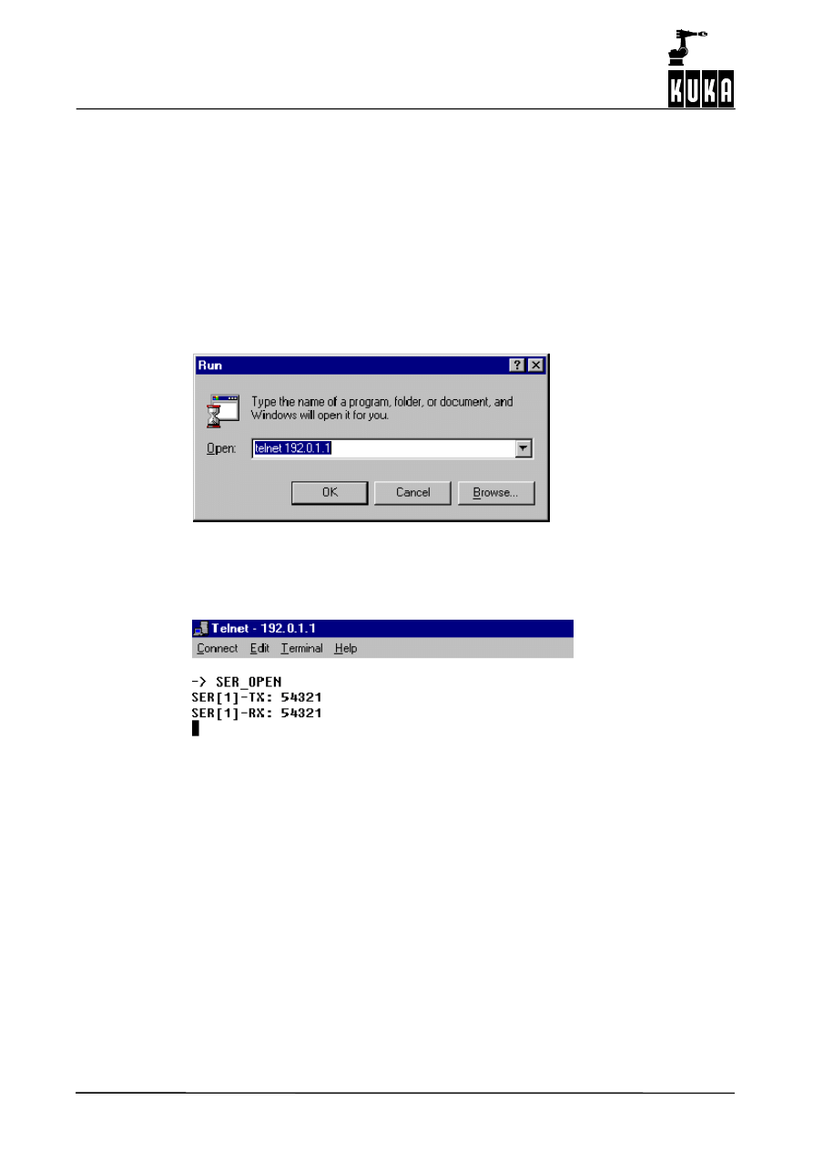
3.8
Diagnosis
Telnet makes it possible to display data that have been transmitted and received. For this,
the following setting must be made in the file “SERIAL.INI” in the directory
“C:\KRC\Roboter\INIT”:
[TEST]
TESTPRINT = 1
Telnet itself is called by pressing the Windows Start button and calling the command “Run”.
Enter the string “telnet 192.0.1.1” in the selection box “Open” and press OK:
Once CREAD/CWRITE has transmitted the integer value 54321 and it has been mirrored
by the receiver, the following Telnet window is opened:

3
Commands (continued)
31 of 42
CREAD CWRITE R4.1 07.02.00 en
3.9
Example program for using COPEN, CWRITE, CREAD and CCLOSE
DEFDAT CHANNEL
; -------- Declaration section --------
INT HANDLE, OFFSET
REAL TIMEOUT
INT IS_VALUE, IR_VALUE
REAL R_VALUE
BOOL B_VALUE
DECL STATE_T SR_T, SW_T, SC_T
DECL MODUS_T MR_T, MW_T
ENDDAT
DEF CHANNEL ()
; -------- Initialization --------
MW_T=#SYNC ; initialize synchronous transmission
MR_T=#ABS
; initialize active reading
TIMEOUT=3.0 ; initialize timeout after 3 seconds
IS_VALUE=54321
; -------- Main program --------
OPEN_P( 3 )
SENDEN()
CLOSE_P( 3 )
END
DEF SEND()
; subprogram for reading and writing a value
; writing the IS_VALUE;
CWRITE(HANDLE,SW_T,MW_T,”%d”,IS_VALUE)
; the status component SW_T.RET1 checks whether the transmission was successful
IF (SW_T.RET1<>#CMD_OK) THEN
HALT ;
transmission error
ENDIF
OFFSET=0
;read from 1st character
; read IR_VALUE;
CREAD(HANDLE,SR_T,MR_T,TIMEOUT,OFFSET,”%d”,IR_VALUE)
; the status component SR_T.RET1 checks whether the reading was successful
IF (SR_T.RET1<>#DATA_END) THEN
HALT
; transmission error
ENDIF
IF IR_VALUE<>IS_VALUE THEN
HALT
ENDIF
END
; ------ SP to open the interface channel
DEF OPEN_P (C_NUMBER :OUT ) ;transmit desired channel number
INT C_NUMBER
SWITCH C_NUMBER
CASE 2
COPEN(:SER_2, HANDLE)
CASE 3
COPEN(:SER_3, HANDLE)
DEFAULT
HALT
ENDSWITCH
IF (HANDLE==0) THEN
; channel could not be opened

CREAD CWRITE
32 of 42
CREAD CWRITE R4.1 07.02.00 en
HALT
ENDIF
END
; ------ SP to close the channel
DEF CLOSE_P (C_NUMBER :OUT )
INT C_NUMBER
CCLOSE(HANDLE,SC_T)
; evaluation of the channel status:
IF (SC_T.RET1==#CMD_ABORT) THEN
; channel operation canceled
HALT
ENDIF
END
4
Procedure 3964R and Xon/Xoff protocol
33 of 42
CREAD CWRITE R4.1 07.02.00 en
4
Procedure 3964R and Xon/Xoff protocol
4.1
Procedure 3964R
Procedure 3964R -- an asynchronous, bit--serial transmission procedure – controls the data
flow between a device -- in this case a KR C2 controller -- and a partner device, for example
a second KR C2 controller, a higher--level process computer or an intelligent sensor system.
The interpreter transfers the transmission data to the procedure in so--called output buffers
(TX--BUFFER).
4.1.1
Procedure data
The procedure sends data with the transmission protocol 3964R to the partner device,
repeats the transmission if necessary and signals to the interpreter any errors that cannot
be eliminated.
Incoming data from the connected partner device are stored in input buffers (RX_BUFFER)
and, if correctly received, transferred to the interpreter for further processing.
As procedure 3964R is an asynchronous, bit--serial transmission procedure, the transmitter
and receiver clock rates (baud rate) must be the same for both connected devices.
Control information and user data are sent via the connecting cable. In order to ensure that
every character is recognized by the receiver and to be able to check that the transmission
is error--free, other bits are added before and after the transmitted characters.
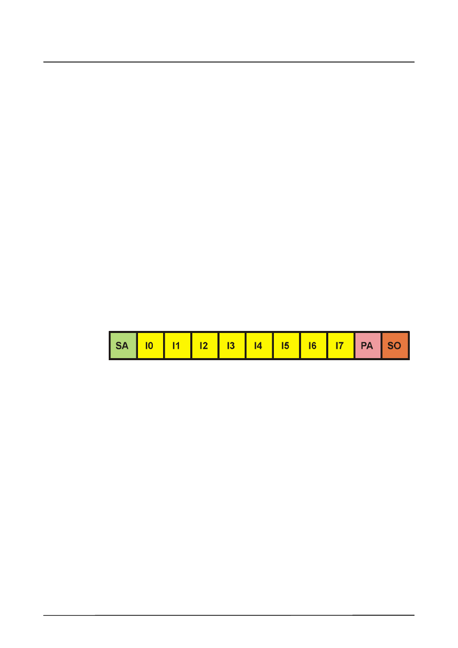
4.1.1.1 Bit sequence
The sequence of the bits is:
Definitions:
SA
Start bit
I0...I7 Information bits
PA
Parity bit
SO
Stop bit
The control characters for procedure 3964R are taken from the DIN 66003 standard for 7--bit
code. The transmission itself, however, uses an 8--bit unit interval with bit 7=0. For the
purposes of data protection, a block check character (BCC) is sent at the end of each data
block.
The block check character, BCC, is the even block parity of the information bits of all data
bytes in a transmitted or received block (EXCLUSIVE OR operation). It begins with the first
user data byte after the connection has been made and ends after the “DLE ETX” character
on termination of the connection. No code is stipulated for the information signals, giving
code transparency.

CREAD CWRITE
34 of 42
CREAD CWRITE R4.1 07.02.00 en
4.1.1.2 Procedure parameters
The procedure parameters described below are set in the file “SERIAL.INI”. This file is
located in the directory “C:\KRC\Roboter\INIT”.
Transmission speed
The transmission speed is given in bits per second (Baud). The preset value in the KR C1
controller is 9600 Baud. Since the Baud rate for both connected devices must be the same,
this is determined by the device with the lower Baud rate.
Possible values are: 115200, 57600, 38400, 19200, 9600, 4800, 2400, 1200, 600, 300, 150
and 110 Baud.
Setting the transmission speed in the file “SERIAL.INI”:
[COM1]
BAUD=9600
...
[COM2]
BAUD=9600
...
Priority
In order to avoid initialization conflicts – should both devices attempt simultaneously to
execute an active transmission – the priority can be set.
The opposite priority must always be set for the partner device. The following options are
available:
--
higher priority
(high)
--
low priority
(low)
If, for example, the KR C2 controller has the higher priority, the lower priority is assigned
to the partner device and vice versa.
Setting the priority in the file SERIAL.INI
[3964R]
...
PROTOCOL_PRIOR=1
; HIGH=1, LOW=0
The value “1” signifies higher priority, the value “0” low priority.
4.1.1.3 Variable specifications for procedure 3964R
For procedure 3964R, the number of data bits and the parity must be specified:
Data bits:
8, 7
Parity:
even, odd, none
4.1.1.4 Fixed specifications for procedure 3964R
The following is permanently defined for procedure 3964R:
Stop bits
1

4
Procedure 3964R and Xon/Xoff protocol (continued)
35 of 42
CREAD CWRITE R4.1 07.02.00 en
4.1.1.5 Procedure 3964R settings in the file SERIAL.INI
[3964R]
CHAR_TIMEOUT=500
; msec
Character delay time
QUITT_TIMEOUT=500
; msec
Acknowledgement delay time
TRANS_TIMEOUT=2000 ; msec
Wait time
MAX_TX_BUFFER=2
; 1..5
Max. no. of transmit buffers
MAX_RX_BUFFER=10
; 1..20
Max. no. of receive buffers
SIZE_RX_BUFFER=100
; 1..2048
Size of receive buffers
PROTOCOL_PRIOR=1
; HIGH=1, LOW=0 Priority
4.1.2
Transmission with procedure 3964R
4.1.2.1 Establishing the connection
In order to make a connection, procedure 3964R sends out the control character “STX”. If
the partner device responds within the acknowledgement delay time “QUITT_TIMEOUT”
(default: 500 ms) with the character “DLE”, the procedure switches to transmission mode.
If the partner device responds with “NAK”, or any character or string other than “DLE”, or the
acknowledgement delay time (QUITT_TIMEOUT) elapses without a response, the
connection has failed.
After a total of six failed attempts to make a connection, the procedure cancels the process,
signals the error to the interpreter and sends the character “NAK” to the partner device.
4.1.2.2 Sending information
If the connection is successfully established, the user data contained in the current output
buffer is sent to the partner device at the selected transmission speed. The partner device
monitors the time interval between incoming characters. The interval between two
characters may not exceed the character delay time “CHAR_TIMEOUT” (default: 500 ms).
Every “DLE” character contained in the buffer is transmitted as two “DLE” characters, i.e. a
datum (10H) is sent twice (DLE duplication). See also Section 4.1.3.2.
Once the contents of the buffer have been sent, the procedure adds the characters “DLE”,
“ETX” and “BCC” as an end label and waits for an acknowledgement character. If the partner
device sends the character “DLE” within the acknowledgement delay time
(QUITT_TIMEOUT), the data block has been correctly received.
If the partner device responds with “NAK” or with any character or string other than “DLE”,
or if the acknowledgement delay time elapses with no reaction, the procedure begins the
transmission again with the connection set--up “STX”.
After a total of six failed attempts to send the data block, the procedure cancels the process,
signals the error to the interpreter and sends the character “NAK” to the partner device.
If the partner device sends the character “NAK” while a transmission is in progress, the
procedure terminates the block and repeats the transmission as described above. In the
event of a different character, the procedure first waits for the character delay time
(CHAR_TIMEOUT) to elapse and then transmits “NAK” to bring the partner device back to
the rest condition. The procedure then begins the transmission again with the connection
set--up “STX”.
CREAD CWRITE
36 of 42
CREAD CWRITE R4.1 07.02.00 en
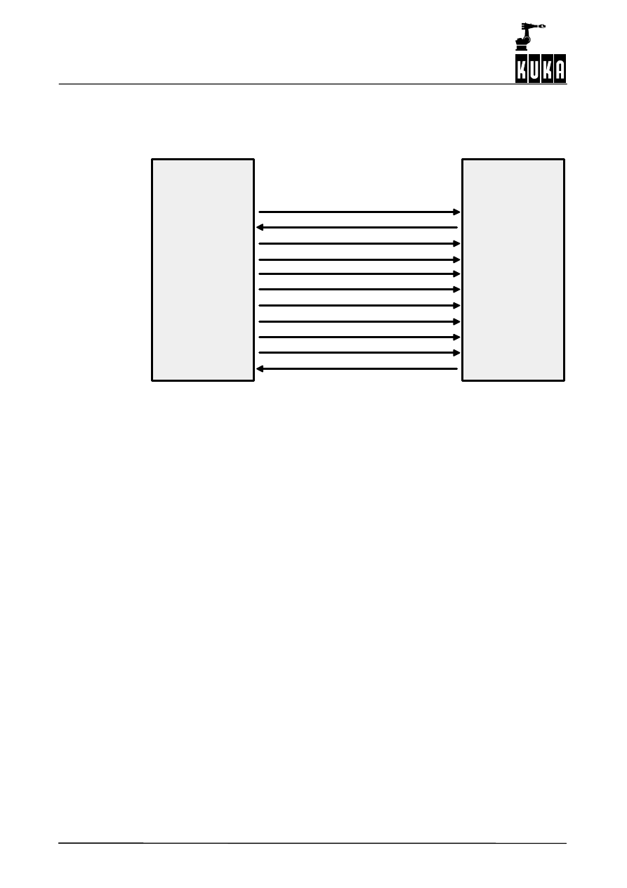
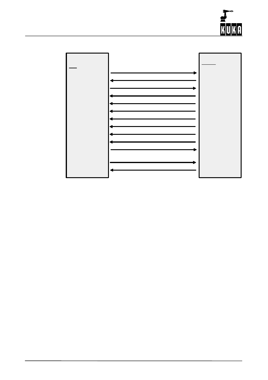
4.1.2.3 KR C2 sends data
The following is an example of error--free data traffic. The KR C2 sends data to the partner
device.
KR C2
Procedure
3964R
Partner device
STX
DLE
ETX
DLE
1st character
DLE
nth character
2nd character
...
...
BCC
4.1.3
Receiving with procedure 3964R
4.1.3.1 Rest condition
In the rest condition, i.e. when there is no transmission request to process, procedure 3964R
waits for a connection to be established by the partner device.
If the procedure in the rest condition receives any character (except STX), it waits for the
character delay time “CHAR_TIMEOUT” to elapse and then sends the character “NAK”. This
error is signaled to the interpreter.
4.1.3.2 Receiving information
If the procedure receives the character “STX”, and if it has an empty input buffer, it answers
with “DLE”. Incoming characters are now stored in the input buffer.
If two consecutive “DLE” characters are received, only one “DLE” character is placed in the
input buffer. See also Section 4.1.2.2.
If the input buffer is already full when the partner device commences the connection set--up,
the full buffer is transferred to the interpreter and further incoming characters are placed in
a second input buffer.
After each character is received, the procedure waits the character delay time
(CHAR_TIMEOUT) for the next character. If the character delay time elapses without any
further characters being received, the “NAK” character is sent to the partner device and the
error is signaled to the interpreter.
If the procedure identifies the character string “DLE”, “ETX” and “BCC”, the reception is
terminated. The received block check character “BCC” is compared with the internally
generated block parity.
If the block check character is correct and no other receiving errors have occurred, the
procedure sends the character “DLE”. The procedure transfers the contents of the input
buffer to the interpreter and returns to the rest condition.
4
Procedure 3964R and Xon/Xoff protocol (continued)
37 of 42
CREAD CWRITE R4.1 07.02.00 en
If the “BCC” is incorrect, an “NAK” character is sent to the partner device. The procedure then
waits for the transmission to be repeated.
If the block has still not been received without errors after six attempts, or if the partner device
does not repeat the transmission within the wait time “TRANS_TIMEOUT” (2000 ms by
default), procedure 3964R cancels the reception and signals the error to the interpreter.
If transmission errors occur during reception (e.g. lost characters, frame errors, parity
errors), reception continues until the connection is terminated, at which time “NAK” is sent
to the partner device. The procedure then waits for the transmission to be repeated as
described above.
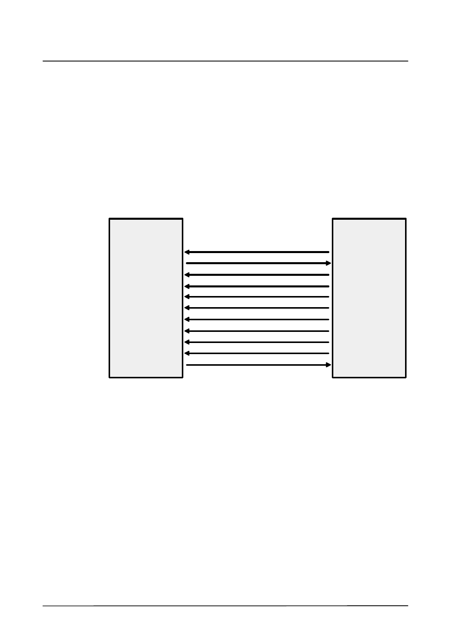
4.1.3.3 KR C2 receives data
The following is an example of error--free data traffic. The KR C2 receives data from the
partner device.
KR C2
Procedure
3964R
Partner device
DLE
STK
1st character
2nd character
...
...
nth character
DLE
ETX
BCC
DLE
4.1.4
Initialization conflicts
If the receiving device responds to the “STX” character, not with the acknowledgement “DLE”
or “NAK” within the acknowledgement delay time (QUITT_TIMEOUT), but instead also with
the character “STX”, an initialization conflict has occurred.
Should both devices attempt simultaneously to execute an active transmission request, the
order is determined by the priority settings that have been made.
The device with the lower priority withdraws its transmission request and answers with the
character “DLE”. In this way, the device with the higher priority can send its data.
Once the connection has been terminated, the device with the lower priority can carry out
its transmission.
CREAD CWRITE
38 of 42
CREAD CWRITE R4.1 07.02.00 en
Example of error--free data traffic
KR C2
Procedure 3964R
low priority
Partner device
higher priority
STX
STX
1st character
2nd character
...
nth character
DLE
ETX
BCC
DLE
DLE
STX
DLE
4.2
Xon/Xoff protocol
Handshake procedures, also known as low--level protocols, are used to stop the partner
station’s transmitter when the input buffer is in danger of overflowing.
Along with “RTS/CTS”, the “Xon/Xoff” protocol is a common handshake procedure that is
easy to implement. Every incoming character is monitored to see if it is a protocol character.
A software handshake using the “Xon/Xoff” procedure presupposes that neither of the
protocol characters “Xon” or “Xoff” are present in the transmission data of the application
programs communicating with one another.
“Xon/Xoff” settings in the file SERIAL.INI
In the KR C2, the “Xon/Xoff” settings are made in the file “SERIAL.INI”. This file is located
in the directory “C:\KRC\Roboter\INIT”.
[XONXOFF]
CHAR_TIMEOUT=50
; msec Timeout after last received character
; to recognize the end of telegram
MAX_TX_BUFFER=2
; 1..5
MAX_RX_BUFFER=2
; 1..20
SIZE_RX_BUFFER=100
; 1..2048 longest expected telegram length +
; 15 characters
XON_VAL=17
; 0..255
XON
character (decimal)
XOFF_VAL=19
; 0..255
XOFF character (decimal)
; if XON_VAL=0 and XOFF_VAL=0 then XON/XOFF-
; protocol is disabled (pure communication)
DSR_LINE=0
; 0 = DSR line not connected, 1 = DSR line
must be high
5
Serial interfaces
39 of 42
CREAD CWRITE R4.1 07.02.00 en
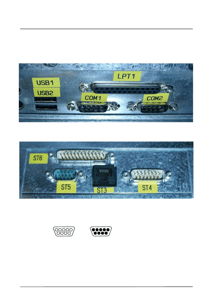
5
Serial interfaces
The KR C2 controller has three serial interfaces:
COM1, COM2 and COM3, all 3 designed as 9--pole Sub--D connectors.
COM3 is labeled as ST5 on the connector panel:
5.1
Sub--D connector, 9 pins
(Female)
(Male)
5
1
1
5
6
9
9
6
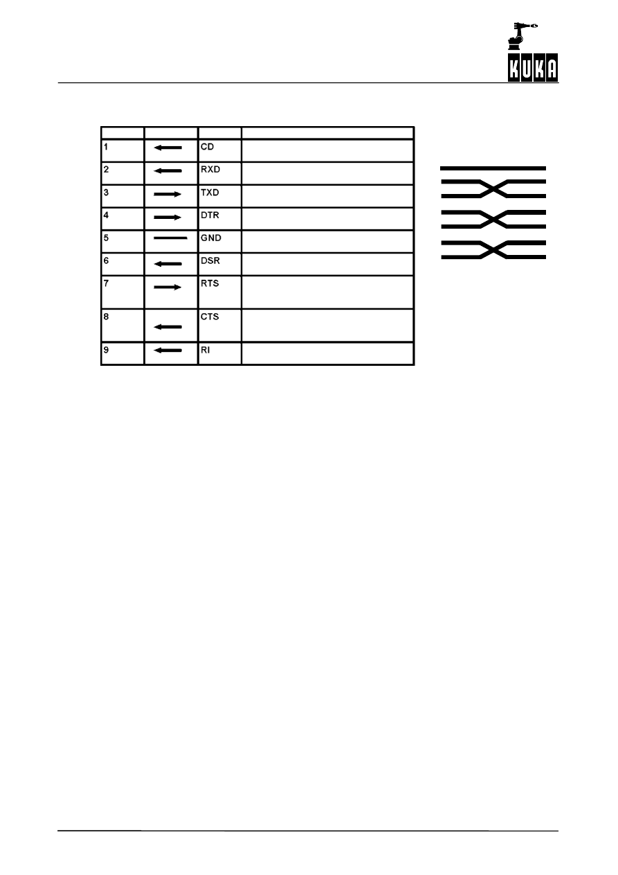
CREAD CWRITE
40 of 42
CREAD CWRITE R4.1 07.02.00 en
5.2
Connector pin allocation for Sub--D, 9 pins
5
2
3
4
6
7
8
5
2
3
4
6
7
8
PIN
Direction Name
Description
Carrier Detect
(Telephone answered)
Receive Data
(Data line -- receive)
Transmit Data
(Data line -- transmit)
Data Terminal Ready
(Handshake -- output for DSR)
System Ground
(Ground)
Data Set Ready
(Handshake -- input for DTR)
Request to Send
(Handshake -- request to
send)
Clear to Send
(Handshake -- input for RTS from
partner)
Ring indicator
(Telephone bell)
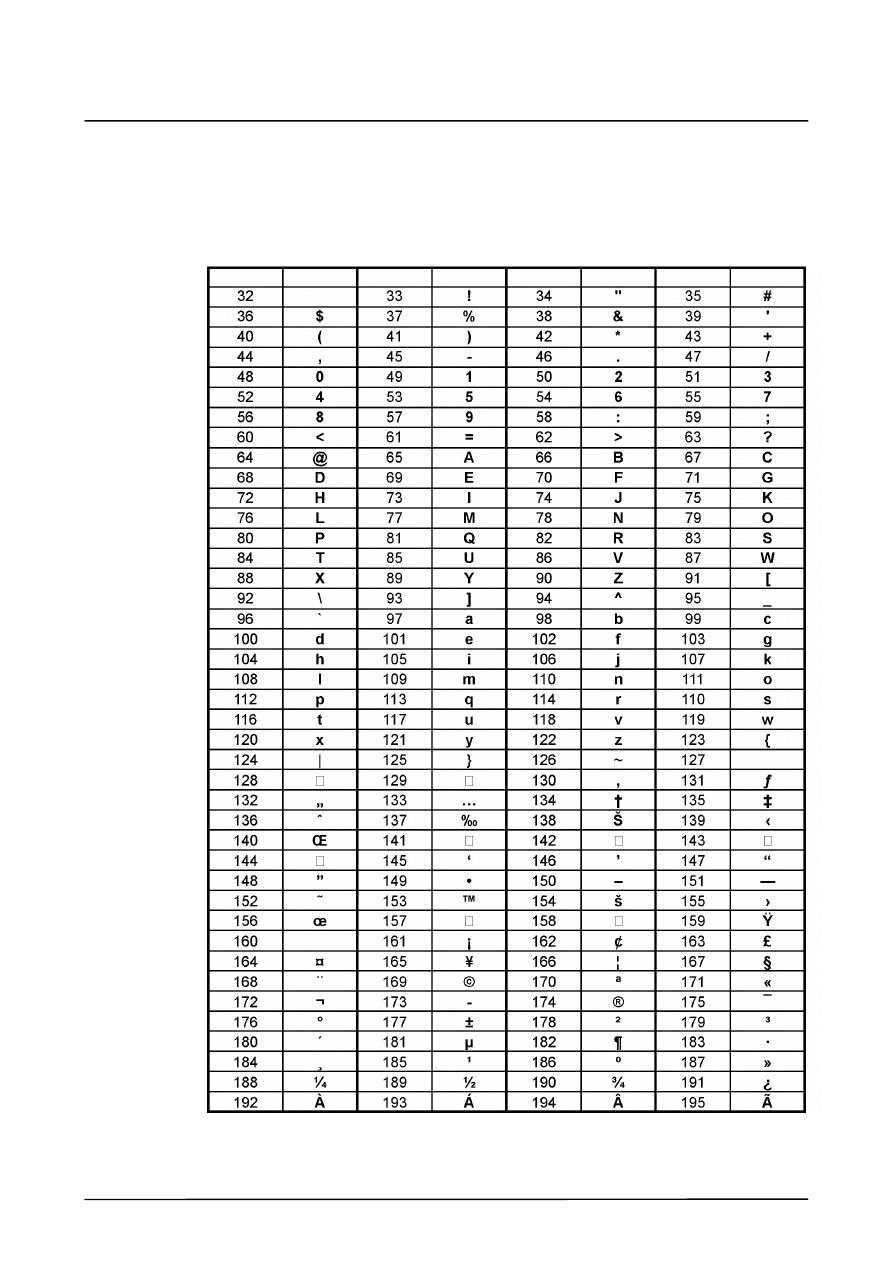
6
Appendix
41 of 42
CREAD CWRITE R4.1 07.02.00 en
6
Appendix
6.1
ASCII character map
Number Character
(space)
Number Character Number Character Number Character
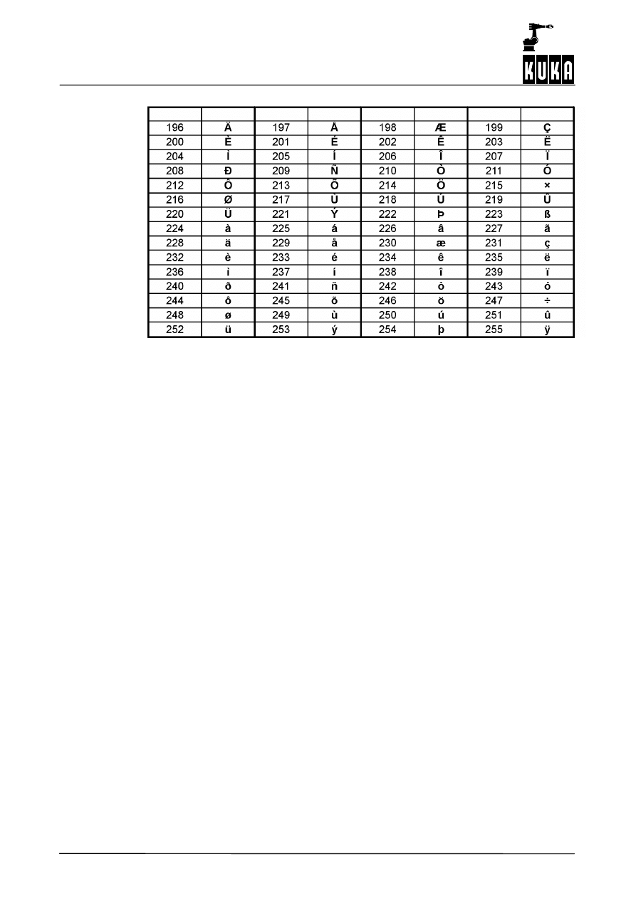
CREAD CWRITE
42 of 42
CREAD CWRITE R4.1 07.02.00 en
Number Character Number Character Number Character Number Character
1

Index
Index -- i
Symbols
$CMD, 11, 18
$CUSTOM.DAT, 11
$DATA_SER1, 15
$DATA_SER2, 15
$DATA_SER3, 15
$PSER_X, 8
%FWGU, 15, 19, 26, 27
Numbers
3964R, 33, 35
A
ABS, 13, 14, 17
Acknowledgement delay time, 35
Active reading, 14
Assignment of a serial channel, 7
ASYNC, 18
B
Baud rate, 33
BAUD=, 34
BCC, 33, 35
Bit sequence, 33
Block check character, 33
C
C Programming Language, 17
CCLOSE, 24
CHANNEL, 11
Channel_Name, 11, 12
CHAR_TIMEOUT, 35, 36
Character delay time, 35
CMD_ABORT, 13, 18, 24, 27
CMD_OK, 13, 18, 24, 27
CMD_REJ, 18
CMD_STAT, 13, 18
CMD_SYN, 18
CMD_TIMEOUT, 13
COM1, 5, 34, 39
COM2, 5, 34, 39
COM3, 5, 7, 39
COND, 14, 17
Conversion character, 17
COPEN, 12
CREAD, 13
CWRITE, 18
D
DATA_BLK, 13
DATA_END, 13
DATA_OK, 13, 18
DLE, 35
DLE ETX, 33
E
ENUM value, 16
Establishing the connection, 35
ETX, 35
F
FMT_ERR, 13, 18
Format, 14, 17, 19, 25, 27
FPRINTF, 19
H
Handle, 12, 13, 18, 24, 25
Handshake procedures, 38
Hardware prerequisites, 5
HITS, 13, 18, 27
HW_INF.INI, 7
I
IEEE 754 standard format, 17
Information bit, 33
Initialization conflicts, 37
Input buffer full, 36
Interface_Name, 11
L
LENGTH, 13
Little endian format, 17
Low--level protocol, 38
M
Max. no. of receive buffers, 35
Max. no. of transmit buffers, 35
MAX_RX_BUFFER, 35
MAX_TX_BUFFER, 35
Mode, 14, 18
MODUS_T, 14, 18
Motherboard Soyo SY--7VBA 133u, 5

Index
Index -- ii
Motherboard SuperMicro 370SBA, 5
Mouse drivers, 5
MR_T, 31
MW_T, 31
N
NAK, 35
O
OFFSET, 27
Offset, 14, 25
P
Parity bit, 33
Passive reading, 14
Port, 5
Priority, 34, 35, 37
Procedure 3964R, 33
Procedure data, 33
Procedure parameters, 34
PROTOCOL_PRIOR, 34, 35
Q
QUITT_TIMEOUT, 35, 37
R
Receive buffers, 35
Receiving information, 36
Receiving with procedure 3964R, 36
RX_BUFFER, 33
S
Sending information, 35
SEQ, 14
SER_1, 5, 11, 14
SER_2, 5, 11, 14
SER_3, 5, 11, 12
Serial interface, 39
SERIAL.INI, 7, 30, 34
Size of receive buffers, 35
SIZE_RX_BUFFER, 35
Software handshake, 38
SREAD, 26
ST5, 39
Start bit, 33
State, 13, 17, 18, 24, 25, 27
STATE.MSG_NO, 27
STATE_T, 9, 13, 18
Stop bit, 33
String1, 27
Structure_Variable, 11
STX, 35
Sub--D connector, 9 pins, 40
SWRITE, 27
SYNC, 18
T
Timeout, 14
TRANS_TIMEOUT, 35, 37
Transmission error, 37
Transmission speed, 34
Transmission with procedure 3964R, 35
Transmit buffers, 35
TX--BUFFER, 33
V
VALUE, 27
Var, 14, 19
W
Wait, 15
Wait_Time, 35
X
Xon/Xoff protocol, 38
Document Outline
- General
- Configuration
- Commands
- CHANNEL
- COPEN
- CREAD
- CWRITE
- Syntax
- Definition, description
- Examples
- Conversion of an integer value into decimal and hexadecimal notation
- Writing an integer value in binary notation
- Writing of the first 5 array elements of an array
- Output of values of all array elements of an array
- Output of the first initialized array elements
- Writing of the first 50 elements of a character string
- Conversion of the ENUM constants into ASCII format
- Writing of two real values with text
- Writing to the command channel
- CCLOSE
- SREAD
- SWRITE
- Diagnosis
- Example program for using COPEN, CWRITE, CREAD and CCLOSE
- Procedure 3964R and Xon/Xoff protocol
- Serial interfaces
- Appendix
Wyszukiwarka
Podobne podstrony:
fun160 file reg read write en (1)
Idioms (100) from Speak Read Write com
Read Around Write, Read Around Write
lets read and write about(2)
lets read and write about(1)
lets read and write about
islcollective lets read and write about 4family and friends my uncle 35384d5fa86f75ce44 13324813
PANsound manual
als manual RZ5IUSXZX237ENPGWFIN Nieznany
How to read the equine ECG id 2 Nieznany
hplj 5p 6p service manual vhnlwmi5rxab6ao6bivsrdhllvztpnnomgxi2ma vhnlwmi5rxab6ao6bivsrdhllvztpnnomg
BSAVA Manual of Rabbit Surgery Dentistry and Imaging
Okidata Okipage 14e Parts Manual
Bmw 01 94 Business Mid Radio Owners Manual
Manual Acer TravelMate 2430 US EN
manual mechanika 2 2 id 279133 Nieznany
4 Steyr Operation and Maintenance Manual 8th edition Feb 08
więcej podobnych podstron