
Initial Print Date: 10/03
Table of Contents
Subject
Page
Purpose of the System . . . . . . . . . . . . . . . . . . . . . . . . . . . . . . . . . . . . . . . .3
E83 Chassis Dynamics . . . . . . . . . . . . . . . . . . . . . . . . . . . . . . . . . . . . . . . . . .3
System Components . . . . . . . . . . . . . . . . . . . . . . . . . . . . . . . . . . . . . . . . . .3
Front Axle . . . . . . . . . . . . . . . . . . . . . . . . . . . . . . . . . . . . . . . . . . . . . . . . . . . .3
Mechanical Components . . . . . . . . . . . . . . . . . . . . . . . . . . . . . . . . . . . . . . . .4
Technical Data . . . . . . . . . . . . . . . . . . . . . . . . . . . . . . . . . . . . . . . . . . . . . . . . .4
Workshop Hints . . . . . . . . . . . . . . . . . . . . . . . . . . . . . . . . . . . . . . . . . . . . . . . .5
Alignment and Camber Adjustment . . . . . . . . . . . . . . . . . . . . . . . . . . . .5
Strut Replacement . . . . . . . . . . . . . . . . . . . . . . . . . . . . . . . . . . . . . . . . . . .5
Spring Replacement . . . . . . . . . . . . . . . . . . . . . . . . . . . . . . . . . . . . . . . . . .5
Reinforcement Plate . . . . . . . . . . . . . . . . . . . . . . . . . . . . . . . . . . . . . . . . . .5
Rear Axle . . . . . . . . . . . . . . . . . . . . . . . . . . . . . . . . . . . . . . . . . . . . . . . . . . . . .5
Technical Data . . . . . . . . . . . . . . . . . . . . . . . . . . . . . . . . . . . . . . . . . . . . . . . . .6
Workshop Hints . . . . . . . . . . . . . . . . . . . . . . . . . . . . . . . . . . . . . . . . . . . . . . . .6
Adjustment of Rear Wheel Alignment . . . . . . . . . . . . . . . . . . . . . . . . . . .6
Lowering (removing) the Rear Axle . . . . . . . . . . . . . . . . . . . . . . . . . . . . .6
Brakes . . . . . . . . . . . . . . . . . . . . . . . . . . . . . . . . . . . . . . . . . . . . . . . . . . . . . . . .7
Mechanical Components . . . . . . . . . . . . . . . . . . . . . . . . . . . . . . . . . . . . . . . .7
Hydraulic Unit with Vacuum Brake Booster and DSC Hydraulic
Module . . . . . . . . . . . . . . . . . . . . . . . . . . . . . . . . . . . . . . . . . . . . . . . . . . . . .8
Foot Controls with Brake and Clutch Pedals . . . . . . . . . . . . . . . . . . . . .8
Parking Handbrake Lever, ASZE, Cables and Duo-Servo Brakes. . .8
Workshop Hints . . . . . . . . . . . . . . . . . . . . . . . . . . . . . . . . . . . . . . . . . . . . . . . .8
Changing Cables . . . . . . . . . . . . . . . . . . . . . . . . . . . . . . . . . . . . . . . . . . . . .8
Steering . . . . . . . . . . . . . . . . . . . . . . . . . . . . . . . . . . . . . . . . . . . . . . . . . . . . . .9
Wheels and Tires . . . . . . . . . . . . . . . . . . . . . . . . . . . . . . . . . . . . . . . . . . . .10
Tire Deflation Warning (RDW) . . . . . . . . . . . . . . . . . . . . . . . . . . . . . . . . . . .11
E83 Chassis Dynamics
Revision Date:

2
E83 Chassis Dynamics
Chassis Dynamics
Model: E83
Production: Start of Production MY 2004
After completion of this module you will be able to:
• Visually identify the suspension components that are unique to the E83
• Describe the steering system mechanical/hydraulic components
• Demonstrate how to access, remove and install the spare wheel
• Explain how to initialize RDW

Purpose of the System
E83 Chassis Dynamics
As with all BMW vehicles, the X3 chassis and suspension was designed with particular
emphasis on driving pleasure, dynamics and favorable handling.
The main aim in the full development of the X3 was to achieve:
• Agility on the road
• Driving dynamics
• Stability
• Traction
The front axle is a double joint spring strut axle with tension arms and a rack and pinion
steering system with hydraulic power assist. Conventional rack and pinion power steer-
ing is installed to the E83 as standard. Servotronic is available as an option. Spring
struts with coil springs and twin tube gas-pressure dampers are used on the front axle.
It is similar the front axle of the E53.
The rear axle design is based on the E46/16 with barrel springs and separate twin tube
gas-pressure dampers.
The brake system is a hydraulic dual-circuit brake system with "front/rear split" vacuum
boost power assist and EBV. The parking brake actuating unit is located in the center
console and is equipped with an automatic cable adjuster (ASZE) and a compensating
element.
Several different wheel and tire combinations are available for the E83. The spare wheel
(steel) is located in a special bracket under the luggage compartment floor in the rear.
The tire deflation warning (RDW) is a standard feature on the E83.
System Components
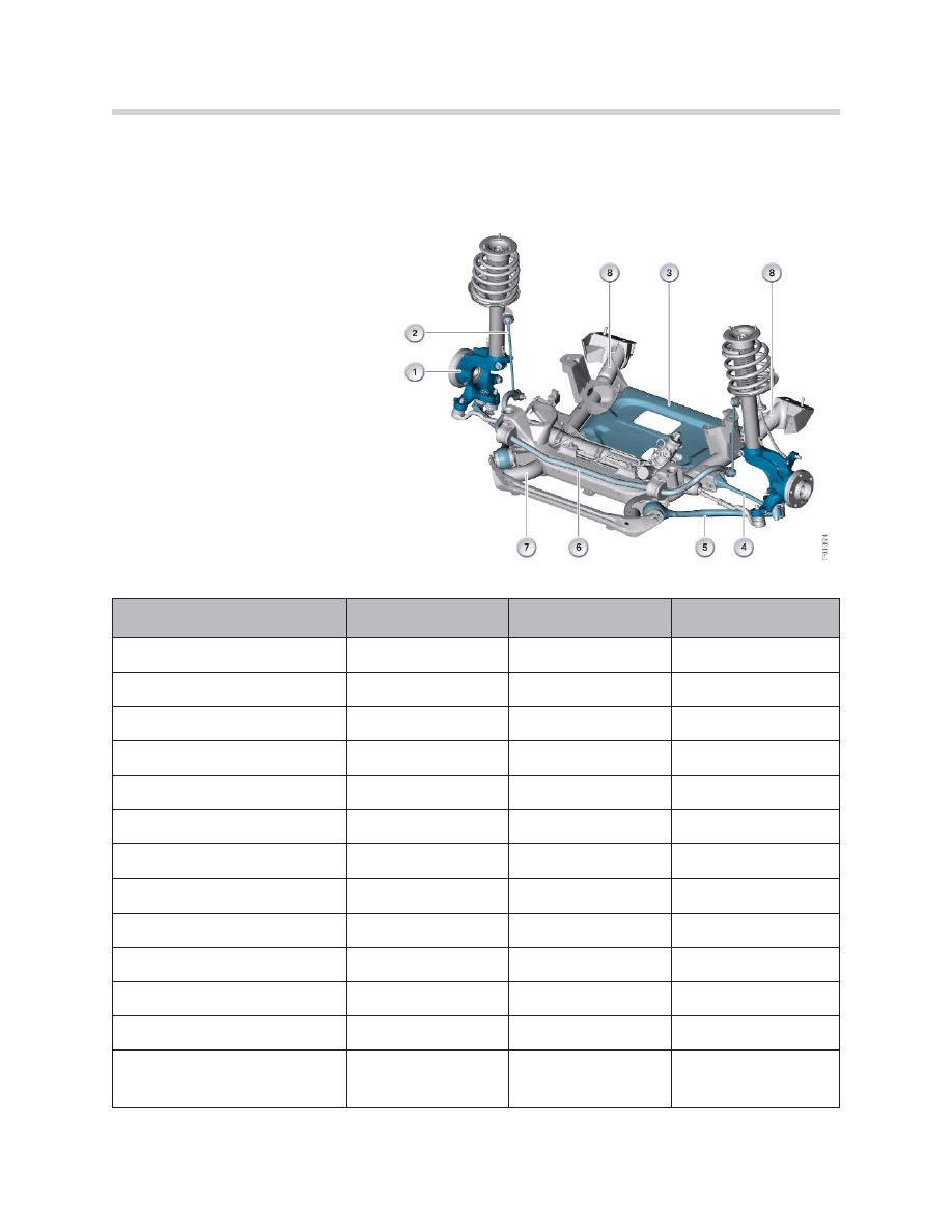
Front Axle
Specific components in the E83 (subject to additional load) are designed as forged
steel parts.
• Control arms: forged steel with rubber mount
• Tension arms: forged steel with hydraulic bushing
• Swivel bearing: forged steel, track arm forged on
3
E83 Chassis Dynamics
A reinforcement plate (thrust panel) is bolted to the front axle carrier. This makes a contri-
bution to the rigidity of the front structure and suspension. There are two recesses in this
thrust zone for accessibility to the engine oil drain plug (rectangular recess on 6 cylinder
engines).
Mechanical Components
1. Swivel bearing
2. Anti-roll bar link (attached to strut tube)
3. Thrust panel
4. Control arm
5. Tension arm
6. Anti-roll bar
7. Front axle carrier
8. Axle carrier rear mounts
Technical Data
Wheels
7Jx17
8Jx17
8Jx18
Tires
215/60
235/55
235/50
Rim offset (mm)
39
46
46
Track width (mm)
1,537.7
1,523.7
1,523.7
Total toe-in
6º ± 10'
6º ± 10'
6º ± 10'
Min. camber
-20' ± 20'
-20' ± 20'
-20' ± 20'
Camber differential angle
max. 30' left to right max. 30' left to right max. 30' left to right
Caster offset (mm)
25.79
25.79
25.79
Kingpin offset (mm)
-0.88
-7.88
-8.53
Toe difference angle
2º 16' ± 30'
2º 16' ± 30'
2º 16' ± 30'
Steering axis inclination angle 12º 41' ± 30'
12º 41' ± 30'
12º 41' ± 30'
Caster angle
5º 47' ± 30'
5º 47' ± 30'
5º 47' ± 30'
Caster angle differential
max. 30' left to right max. 30' left to right max. 30' left to right
Maximum steering angle
internal 38º
external 31º
internal 38º
external 31º
internal 38º
external 31º
4
E83 Chassis Dynamics
Workshop Hints
Alignment and Camber Adjustment
Toe-in adjustment is performed at the tie rods. If necessary, the camber is corrected by
driving out the pin on the strut tower (spring cup).
Strut Replacement
When replacing the strut, the mounting on the swivel bearing must be expanded with a
special tool.
Spring Replacement
There are new spring tensioners to be used during spring replacement. Refer to Repair
Instructions for detailed information about special tools.
Reinforcement Plate
The vehicle must not be driven without the reinforcement plate in place. The reinforce-
ment plate ensures the transversal rigidity and contributes to the strength of the front
axle.
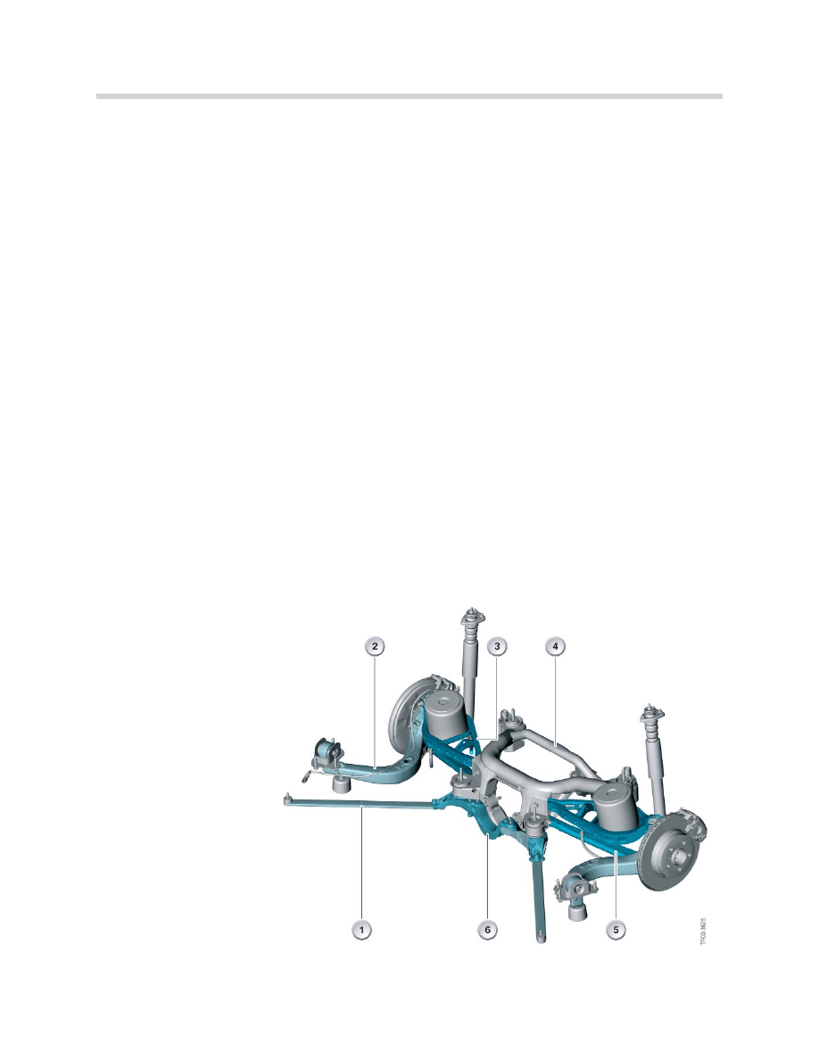
Rear Axle
The E83 is fitted with a central rear axle and subframe. The design of the rear axle is
similar to the E46/16. Two tension arms have been added to the rear axle of the E83
and are secured to the bodyshell.
Mechanical Components
5
E83 Chassis Dynamics
1. Tension arm
2. Trailing arm
3. Upper control arm
4. Rear axle bracket
5. Lower control arm with
plastic cover
6. Thrust brace

Modifications to the E46/16 rear axle to adapt it to the E83:
• Anti-roll bar secured to the rear axle carrier by clamps.
• Front of rear axle carrier suspension converted to special bolts
with additional thrust washer.
• Thrust brace and tension arms.
• Surface of control arms are galvanized steel plates.
• Anti-roll bar link with ball joint attached directly to the control arm.
• Dampers with three point flange (bolt) plate.
Technical Data
Workshop Hints
Adjustment of Rear Wheel Alignment
Rear wheel alignment is adjusted by a special tool on the lower trailing arm (refer to
Repair Information for additional details. The camber is adjusted by an eccentric element
on the lower control arm at the axle carrier connection.
Lowering (removing) the Rear Axle
The handbrake cables (routed through the rear axle carrier and the body console) must
be disengaged before the rear axle is lowered. This is to prevent shearing of the hand-
brake cables.
6
E83 Chassis Dynamics
Wheels
7Jx17
8Jx17
9Jx18
Tires
215/60 R17
235/55 R17
255/45 R18
Rim offset (mm) 39
46
51
Total track width
(mm)
1,611
1,611
1,611
Total toe-in
6º ± 8'
6º ± 8'
6º ± 8'
Camber
-2º ± 15'
-2º ± 15'
-2º ± 15'
Thrust angle
0º ± 4'
0º ± 4'
0º ± 4'
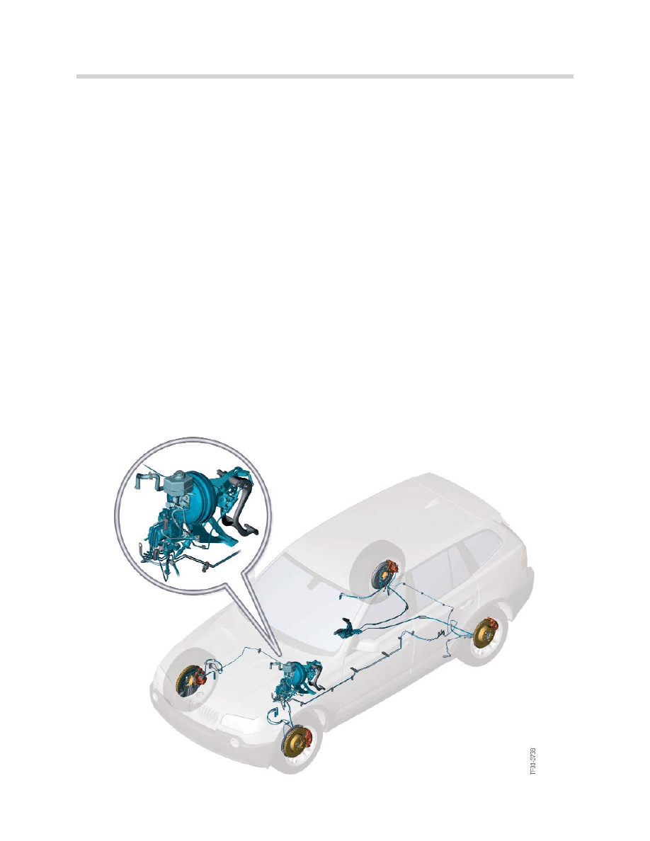
Brakes
The brake system is a hydraulic dual-circuit brake system with "front/rear split", vacuum
boost power assist and EBV. One brake circuit each for the front and rear axles. The
parking brake actuating unit is located in the center console and is equipped with an
automatic cable adjuster (ASZE) and a compensating element.
The advantages of the parking brake with automatic cable adjuster are:
• The 2 cables no longer have to be adjusted during installation.
• Cable extensions (cable conduit) contractions over the operating time are automati-
cally compensated so that the parking brake lever travel is consistent.
• Prestretching of the cables is no longer necessary.
• The parking brake does not have to be adjusted at the end of the assembly line
and in the service department.
• Note: color coded handbrake cables (left/right different part numbers).
Mechanical Components
The brake system consists of the following components:
7
E83 Chassis Dynamics

Four Wheel Hydraulic Disc Brakes
The front brakes are constructed of ventilated brake discs 325mm diameter x 25mm
thick (Geomet coating) with FN57/25 single piston floating calipers.
The rear brake brakes are constructed of ventilated brake discs 320mm diameter x
22mm thick (Geomet coating) with FN42/22 single piston floating calipers.
Hydraulic Unit with Vacuum Brake Booster and DSC Hydraulic Module
The hydraulic unit is located at the front on the left hand side under the main brake cylin-
der. The electric precharging pump is no longer required. All vehicles are equipped with
an 8"/9" tandem brake booster and have a tandem brake master cylinder. The DSC
hydraulic module is a DSC8 system.
Foot Controls with Brake and Clutch Pedals
The essential components of the foot controls are:
• Pedal mounting block
• Brake pedal
• Clutch pedal
• Clutch master cylinder
The pedal mounting block is made of aluminum and is bolted to the bulkhead.
The vehicle has a wide steel brake pedal. The clutch pedal is made of plastic.
Parking Handbrake Lever, ASZE, Cables and Duo-Servo Brakes.
The duo-servo brakes are similar to the duo-servo brakes on the E65 and E53
(185mm diameter x 30mm wide).
The handbrake lever is bolted to the floor pan and is equipped with an automatic cable
adjuster (ASZE) and a compensating element. Refer to ST045 E85 or ST047 E60
Technical Training handouts for additional details on deactivating and activating this unit.
Workshop Hints
Changing Cables
If there is a broken cable, the automatic cable adjuster is in the untensioned position. To
replace the cables, it is necessary to remove the center console and the rear compart-
ment ventilation ducts. For the cables to be removed or parking break shoe replacement,
the parking-brake lever
must be in the released position and the ASZE unit must be
deactivated. Refer to the Repair Instructions or ST045 E85, ST047 E60 Technical
Training handouts for additional details.
8
E83 Chassis Dynamics
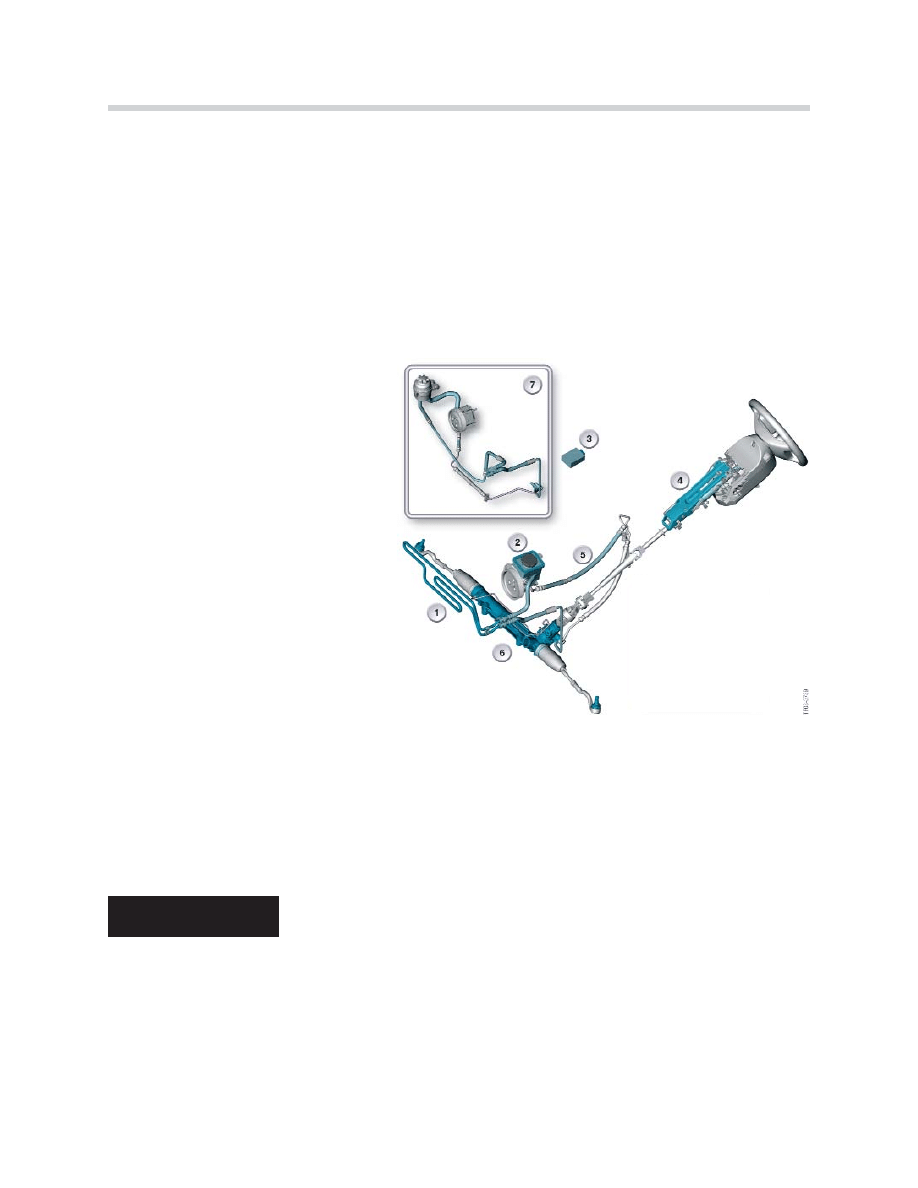
Steering
Conventional rack and pinion power steering is used in the E83 and Servotronic is avail-
able as an option. The design and functioning principle of the Servotronic option are
nothing new but have been modified as described in this chapter.
The servotronic steering system controls the amount of power assistance based on the
current road speed. The hydraulic pressure is electronically adapted to the current road
speed, with greater power assistance available at lower road speeds and less power
assistance available at greater road speeds.
Mechanical/Hydraulic Components
1. Power-steering cooler
2. Hydraulic pump with supply reservoir
(M57TU, diesel)
3. Servotronic control unit
4. Upper steering column assembly
5. Flexible hoses
6. Steering gear
7. Hydraulic pump with separate supply
reservoir (M54B25 and M54B30)
The E83 is equipped with hydraulic assisted rack and pinion steering. The total ratio
of the steering is: 18.9 : 1. The total rack stroke is 81.0 mm (1.7 turns of the steering
wheel). The hydraulic ports on the steering gear have quick release couplings. The
hydraulic pump maximum pressure is limited to 127 bar.
E83 vehicles are equipped with “W” shaped cooling loops (hoses) to assist in cooling.
The hydraulic pump does not have a pump end shutdown feature. The hydraulic pump
could be damaged after approximately 1 minute if the steering is kept on full lock
(end stop) for a long period.
9
E83 Chassis Dynamics
CAUTION!!!
Wheels and Tires
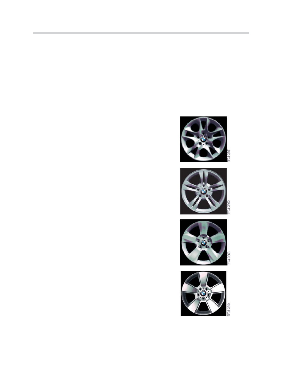
Several different wheel stylings are available. Different 17" wheel stylings are standard
equipment. Other 17" and 18" wheels are available as options, depending on the type
of engine.
A compact wheel (spare/emergency wheel) is standard, regardless of the vehicle version.
The tire deflation warning (RDW) is a standard feature. The RDW function is integrated in
the DSC control unit.
The following wheel/tire combinations are available for US models:
2.5Liter Engine (optional for 3.0 Liter)
• 8.0Jx17 EH2 IS46* (shown to the right)
• 235/55 R17 LI 99** tires
• A/S
• H-rated tires, M+S
3.0 Liter Engine (optional for 2.5 Liter)
• 8.0Jx17 EH2 IS46* (shown to the right)
• 235/55 R17 LI 99** tires
• A/S
• H-rated tires, M+S
Optional (for 2.5 and 3.0)
• 8.0Jx18 EH2 IS46* (shown to the right)
• 235/50 R18 LI 97** tires
• A/S
• H-rated tires, M+S
Optional (for 2.5 and 3.0)
• 8.0Jx18 EH2 IS46* (shown to the right)
• 235/50 R18 LI 97** tires
• A/S
• H-rated tires, M+S
* IS = insert size
** LI = load index
A = all season tires
S = summer tires
10
E83 Chassis Dynamics
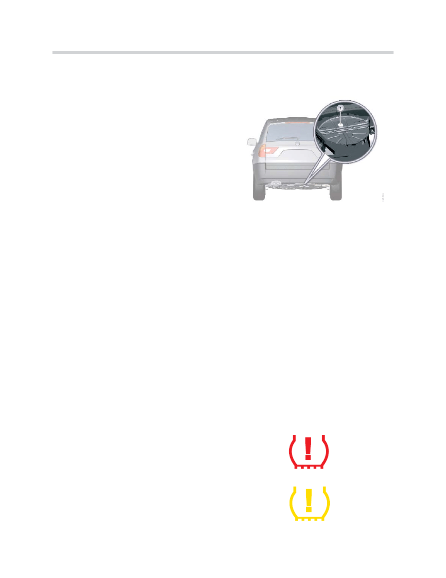
The spare/emergency wheel (compact wheel) is standard equipment. The E83 has a
special bracket for the compact wheel which is located in the vehicle floor under the
luggage compartment and is operated from inside the vehicle.
The release knob is located under the luggage
compartment floor covering next to the tool kit.
The compact wheel is a 4Bx17 IS18 steel
wheel with T135/90 R17 104 M tire.
The compact wheel bracket has a special ser-
vice access cap (1) to check the tire pressure
without having to lower the bracket/wheel.
Tire Deflation Warning (RDW)
The RDW function is integrated (and diagnosed) in the DSC control unit. The system
uses the rotation speed of the diagonally opposite wheels to compare the dynamic cir-
cumferences of all four wheels.
The RDW system does not monitor uniform air pressure loss over all 4 tires. If the pres-
sure loss is the same in all four tires, the wheel speeds change equally and pressure loss
cannot be detected. The customer must continue to check inflation pressures on a regu-
lar basis.
The system must be reinitialized if tire inflation pressures are modified or if the tires/
wheels are replaced. Initializing RDW:
1.Start the engine but do not drive away.
2.Press and hold the RDW button in the center console until the indicator
light in the instrument cluster illuminates in yellow for several seconds.
3.Drive away.
After a certain distance, the system stores the new wheel speeds as reference values and
is then able to display a detected deviation. RDW has an indicator light in the instrument
cluster that may illuminate in yellow or red.
Indicator illuminates in red:
• Indicates a loss of more than 30% of
inflation pressure in one of the tires
• Accompanied by a “gong” sound
Indicator illuminates in yellow :
• Possible faults in the system
• Initialization
11
E83 Chassis Dynamics
Document Outline
- Main Menu
- E83 Complete Vehicle
- E83 Body Electrical
- E83 Safety Systems
- E83 xDrive/DSC
- E83 Drive
- E83 Chassis Dynamics
- X5 Updates
Wyszukiwarka
Podobne podstrony:
więcej podobnych podstron