
Revision Date: 10/07
Initial Print Date: 12/04
Subject
Page
Basic Electricity . . . . . . . . . . . . . . . . . . . . . . . . . . . . . . . . . . . . . . . . . . . . . . .4
Electromotive Force . . . . . . . . . . . . . . . . . . . . . . . . . . . . . . . . . . . . . . . . . . . .6
Theory of Electron Flow . . . . . . . . . . . . . . . . . . . . . . . . . . . . . . . . . . . . . .7
Conventional Theory of Electron Flow . . . . . . . . . . . . . . . . . . . . . . . . . .7
Voltage . . . . . . . . . . . . . . . . . . . . . . . . . . . . . . . . . . . . . . . . . . . . . . . . . . . . .8
Ampere . . . . . . . . . . . . . . . . . . . . . . . . . . . . . . . . . . . . . . . . . . . . . . . . . . . . .9
Ohms . . . . . . . . . . . . . . . . . . . . . . . . . . . . . . . . . . . . . . . . . . . . . . . . . . . . . . .9
Circuits . . . . . . . . . . . . . . . . . . . . . . . . . . . . . . . . . . . . . . . . . . . . . . . . . . . . . . .10
Series Circuit . . . . . . . . . . . . . . . . . . . . . . . . . . . . . . . . . . . . . . . . . . . . . . .10
Parallel Circuit . . . . . . . . . . . . . . . . . . . . . . . . . . . . . . . . . . . . . . . . . . . . . .11
Series-Parallel Circuit . . . . . . . . . . . . . . . . . . . . . . . . . . . . . . . . . . . . . . . .11
Short Circuit . . . . . . . . . . . . . . . . . . . . . . . . . . . . . . . . . . . . . . . . . . . . . . . .11
Ohm’s Law . . . . . . . . . . . . . . . . . . . . . . . . . . . . . . . . . . . . . . . . . . . . . . . . . . .12
Ohm’s Law - Series Circuits . . . . . . . . . . . . . . . . . . . . . . . . . . . . . . . . .13
Ohm’s Law Parallel Circuit - 2 Branches . . . . . . . . . . . . . . . . . . . . . .14
Ohm’s Law Parallel Circuit - more than 2 Branches . . . . . . . . . . . . .15
Ohm’s Law in Series-Parallel Circuit . . . . . . . . . . . . . . . . . . . . . . . . . . .17
Electrical Components . . . . . . . . . . . . . . . . . . . . . . . . . . . . . . . . . . . . . . .22
Magnetic Theory . . . . . . . . . . . . . . . . . . . . . . . . . . . . . . . . . . . . . . . . . . . . . .22
Fundamentals of Magnetism . . . . . . . . . . . . . . . . . . . . . . . . . . . . . . . . . . . .22
Electromagnetic Induction . . . . . . . . . . . . . . . . . . . . . . . . . . . . . . . . . . . . . .24
Generating Voltage . . . . . . . . . . . . . . . . . . . . . . . . . . . . . . . . . . . . . . . . . . . .25
Generator . . . . . . . . . . . . . . . . . . . . . . . . . . . . . . . . . . . . . . . . . . . . . . . . . .25
Alternator . . . . . . . . . . . . . . . . . . . . . . . . . . . . . . . . . . . . . . . . . . . . . . . . . .25
Ignition Coil . . . . . . . . . . . . . . . . . . . . . . . . . . . . . . . . . . . . . . . . . . . . . . . .25
Types of Voltage . . . . . . . . . . . . . . . . . . . . . . . . . . . . . . . . . . . . . . . . . . . . . .26
DC Voltage . . . . . . . . . . . . . . . . . . . . . . . . . . . . . . . . . . . . . . . . . . . . . . . . .26
AC Voltage . . . . . . . . . . . . . . . . . . . . . . . . . . . . . . . . . . . . . . . . . . . . . . . . .26
Conductors, Insulators and Semi-Conductors . . . . . . . . . . . . . . . . . . . .26
Conductors . . . . . . . . . . . . . . . . . . . . . . . . . . . . . . . . . . . . . . . . . . . . . . . .26
Insulators . . . . . . . . . . . . . . . . . . . . . . . . . . . . . . . . . . . . . . . . . . . . . . . . . .27
Semi-Conductors . . . . . . . . . . . . . . . . . . . . . . . . . . . . . . . . . . . . . . . . . . .27
Semi-Conductor Doping . . . . . . . . . . . . . . . . . . . . . . . . . . . . . . . . . . . . .27
N-Type Material . . . . . . . . . . . . . . . . . . . . . . . . . . . . . . . . . . . . . . . . . . . . .28
Table of Contents
Basic Electricity

Subject
Page
P-Type Material . . . . . . . . . . . . . . . . . . . . . . . . . . . . . . . . . . . . . . . . . . . . .28
Junctions . . . . . . . . . . . . . . . . . . . . . . . . . . . . . . . . . . . . . . . . . . . . . . . . . .28
Diode . . . . . . . . . . . . . . . . . . . . . . . . . . . . . . . . . . . . . . . . . . . . . . . . . . . .29
Zener Diode . . . . . . . . . . . . . . . . . . . . . . . . . . . . . . . . . . . . . . . . . . . . . . .29
Light Emitting Diode . . . . . . . . . . . . . . . . . . . . . . . . . . . . . . . . . . . . . . .29
Transistors . . . . . . . . . . . . . . . . . . . . . . . . . . . . . . . . . . . . . . . . . . . . . . . . .30
Relays . . . . . . . . . . . . . . . . . . . . . . . . . . . . . . . . . . . . . . . . . . . . . . . . . . . . .30
Solenoids . . . . . . . . . . . . . . . . . . . . . . . . . . . . . . . . . . . . . . . . . . . . . . . . .31
Switches . . . . . . . . . . . . . . . . . . . . . . . . . . . . . . . . . . . . . . . . . . . . . . . . .31
Resistors . . . . . . . . . . . . . . . . . . . . . . . . . . . . . . . . . . . . . . . . . . . . . . . . .31
Resistor Color Code Guide . . . . . . . . . . . . . . . . . . . . . . . . . . . . . . . .32
Variable Resistors . . . . . . . . . . . . . . . . . . . . . . . . . . . . . . . . . . . . . . . . . . .32
Thermistor . . . . . . . . . . . . . . . . . . . . . . . . . . . . . . . . . . . . . . . . . . . . .32
Potentiometer . . . . . . . . . . . . . . . . . . . . . . . . . . . . . . . . . . . . . . . . . .33
Rheostat . . . . . . . . . . . . . . . . . . . . . . . . . . . . . . . . . . . . . . . . . . . . . . .33
Electric Motors . . . . . . . . . . . . . . . . . . . . . . . . . . . . . . . . . . . . . . . . . . . .33
Stepper Motors . . . . . . . . . . . . . . . . . . . . . . . . . . . . . . . . . . . . . . . . . . . . .33
Common Circuit Designations . . . . . . . . . . . . . . . . . . . . . . . . . . . . . . . . . .34

3
Basic Electricity
Basic Electricity
Model: All
Production: All
After completion of this module you will be able to:
• Understand the theory of Electron Flow vs “Conventional Current Flow”.
• Recognize the different types of electrical circuits.
• Perform Ohm’s law calculations.
• Relate Ohm’s law to practical use in the workshop.
• Understand how different electrical components operate.
• Recognize circuit numbers and abbreviations on ETM’s.
Electricity is defined as the movement of electrons from one atom to another. In order to
understand electricity a basic explanation of the atom is needed.
All matter is made up of molecules. An atom is the smallest particle to which a molecule
can be reduced.
Atoms consist of:
Electrons -Negatively charged particles orbiting around a nucleus.
Protons
-Positively charged particles in the nucleus.
Neutrons
-Uncharged particles in the nucleus that stabilize the protons.
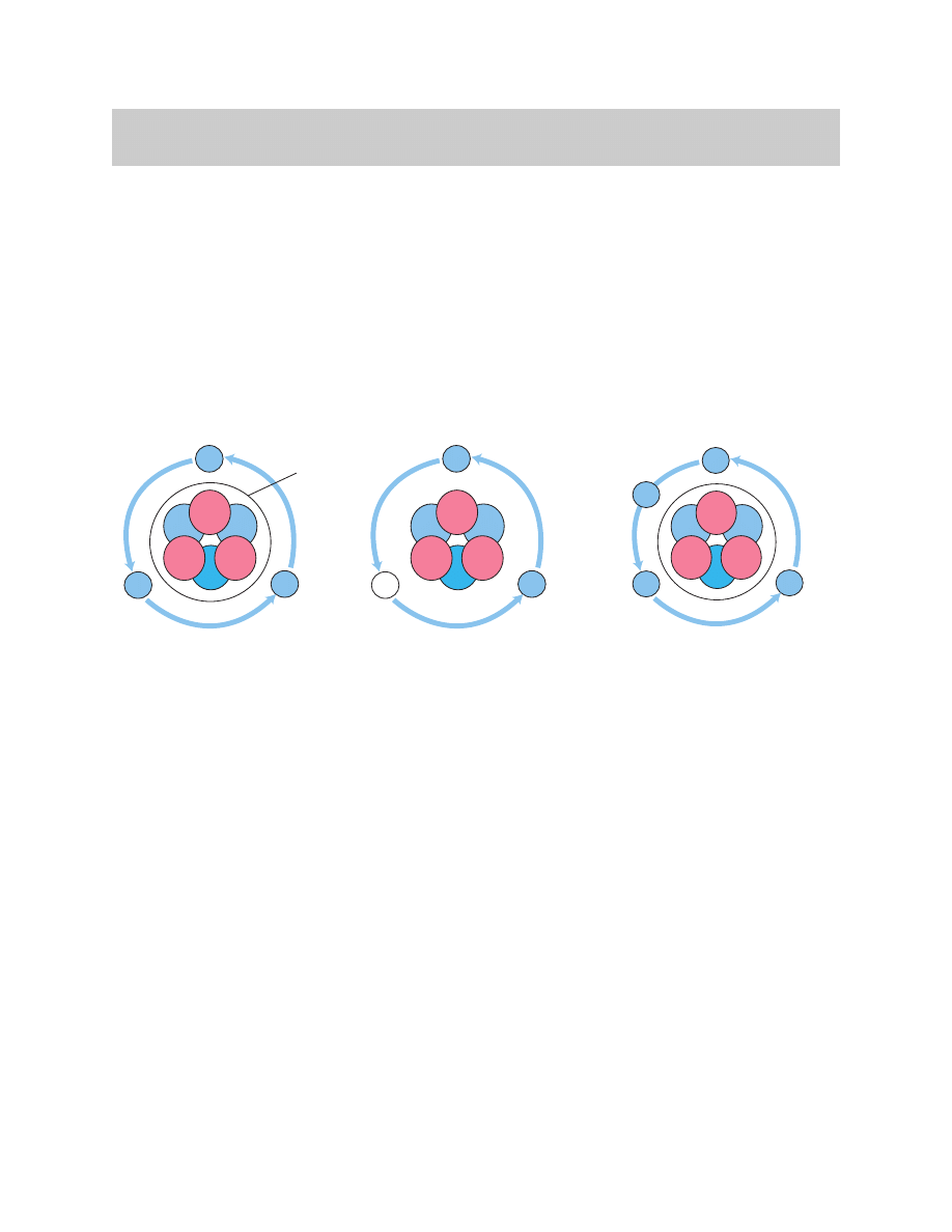
An atom is balanced or displays a neutral charge when the number of protons and elec-
trons are equal.
Through various means (e.g. A chemical reaction in the the automotive battery) elec-
trons are displaced from their normal orbit.
These displaced electrons attach themselves to other atoms, creating an unbalance in
the number of electrons and protons in both atoms.
Atoms which loose or repel an electron become positively charged because of the
greater number of protons. These atoms are called “Positive Ions”.
Atoms which pickup or gain extra electrons become negatively charged and are called
“Negative Ions”.
The negative ions will attempt to repel the extra electron and the positive ions will
attempt to attract it.
Basic Electricity
4
Basic Electricity
+
+
+
_
_
Neutrons
Protons
Electrons
Missing Electron
+
+
+
_
_
_
Neutrons
Protons
Electrons
_
Additional
Electron
+
+
+
_
_
_
Neutrons
Protons
Electrons
Nucleus
Balanced ion
Positive ion
Negative ion
5
Basic Electricity
+
+
+
-
-
-
+
+
+
-
-
-
+
+
+
-
-
-
+
+
+
-
-
-
Copper Wire
+
+
+
-
-
-
+
+
+
-
-
-
+
+
+
-
-
-
+
+
+
-
-
-
Copper Wire
+
-
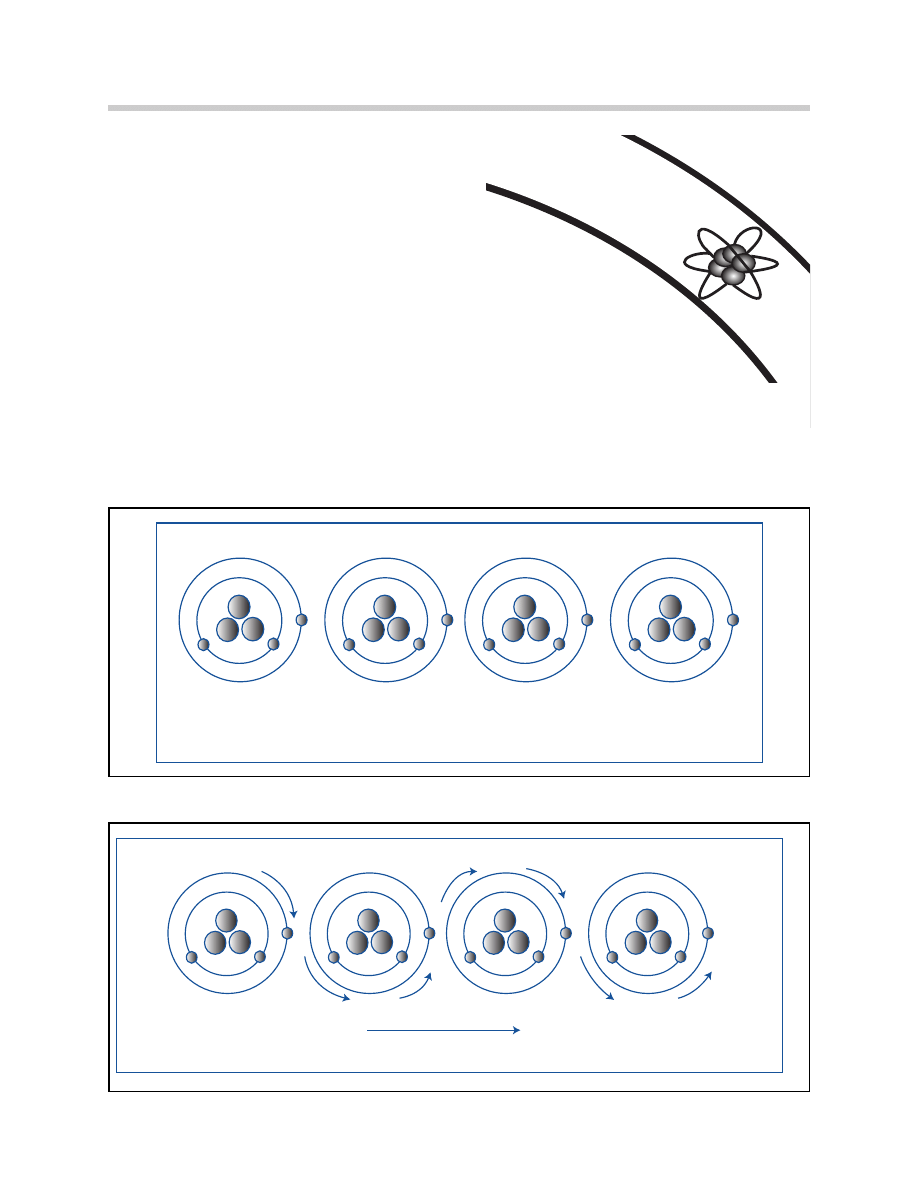
The movement of free electrons from one
atom to another is called electron flow or elec-
tric current flow.
This flow of electrons does not mean that a
single electron travels the entire length of the
wire.
Electron flow is the movement of free elec-
trons from atom to atom and the transmission
of an electrical impulse from one end of a
conductor to the other.
The constant unbalancing and rebalancing of
the atoms takes place in less than one mil-
lionth of a second.
A single strand of copper wire contains
billions of atoms
4 Atoms Shown
No Charge Applied To Wire
Negative
Charge
Electron Flow
Positive
Charge
4 Atoms Shown
Charge Applied To Wire
6
Basic Electricity
Electromotive Force
Friction, light, heat, pressure, chemical reaction or magnetic action are all ways that elec-
trons are freed. The free electrons will move away from the “Electron Moving Force”
(EMF). A stream of free electrons form an electrical current.
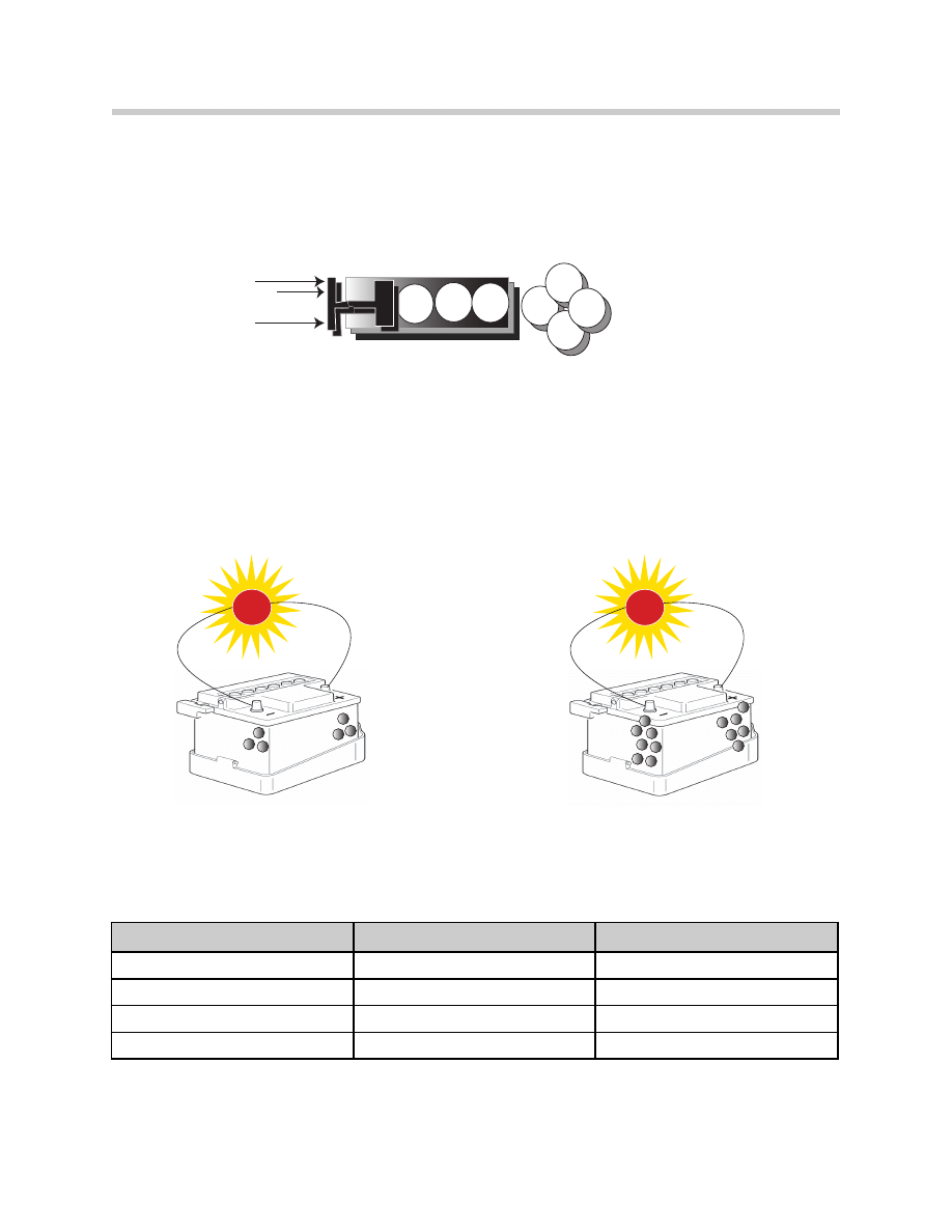
The battery and the generator are the primary and secondary means by which free elec-
trons are generated in automobiles.
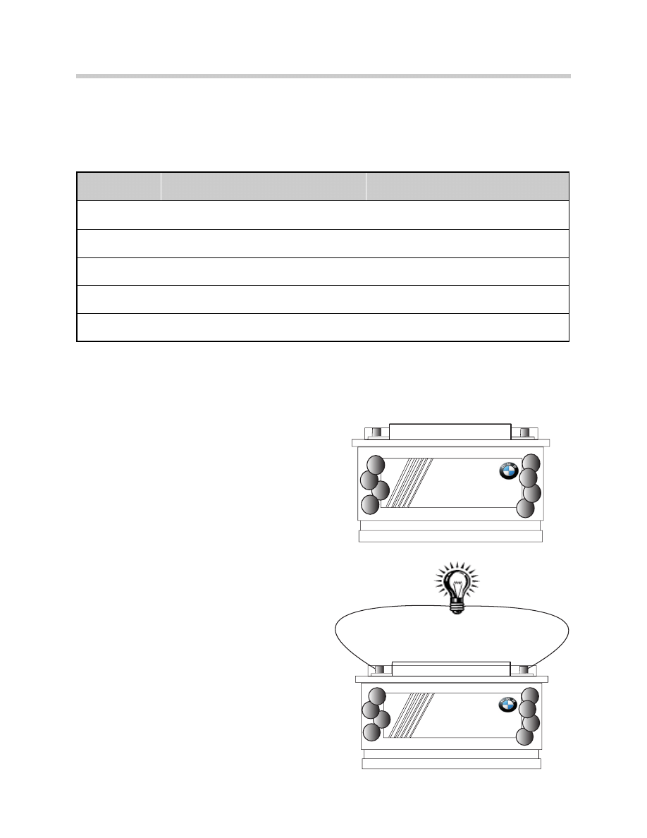
The chemical reaction taking place in the
battery creates an Electromotive Force (EMF)
that provides us with the positive ions and
negative ions.
The generator through magnetic induction is
our other source of free electrons. (Positive
and negative ions)
The positive ions collect at the positive bat-
tery terminal and the negative ions collect at
the negative battery terminal.
The positive and negative ions provide no
energy unless a path between them is estab-
lished. This path is normally in the form of a
load (e.g. bulb, electric motor or other electri-
cal consumer) placed across the positive and
negative terminals of the battery either directly
or through wires.
Positive
Ions
Negative
Ions
+
+
+
+
+
+
_
_
_
_
Positive
Ions
Negative
Ions
+
+
+
+
+
+
_
_
_
_
EMF
Method
Automotive Uses
Friction
Static, Walking Across Carpet
Electrostatic Field, Capacitor
Light
Photoelectric Cell, Light Controls
Headlamp and Mirror Sensors
Pressure
Piezoelectric, Speakers, Microphone
Knock and Side Impact Sensors
Chemical
Dry/Wet Cell Batteries
Primary Automotive EMF, Battery
Magnetic
Electromagnetic Induction, Coils
Secondary Automotive EMF, Generator
7
Basic Electricity
Theory of Electron Flow
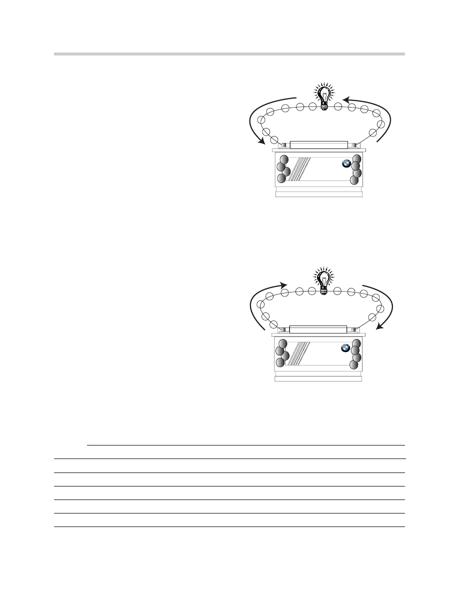
Free electrons are pushed out of the battery
negative terminal through a conductor to the
positive terminal.When a path is established
electrons have a route from the negative termi-
nal to the positive terminal of the battery.
That route may take the electrons through
wires, motors, light bulbs or other electrical
consumers.
The mission of the electrons is always to
return to the source of their energy which is
the battery.
The Theory of Electron Flow represents the
actual path of the electrons in an electrical
circuit, from negative to positive.
Conventional Theory of Electron Flow
Before Science gave a glimpse of the electron,
it was generally believed that electricity (elec-
trons) flowed from the positive charge to the
negative charge.
Most electrical symbols, wiring diagrams, and
teaching is based on the “Conventional Theory
of Electron Flow” which states that electrons
flow from positive to negative.
From this point on all references to current flow
will be defined by the Conventional Theory of
Electron Flow.
Conventional Theory of Electron Flow. is some-
times referred to as the Automotive Theory of
Electron Flow.
Notes:
Positive
Ions
Negative
Ions
+
+
+
+
+
+
_
_
_
_
e
e
e
e
e
e
e
e
e
e
e
e
e
e
e
e
e
e
e
e
e
e
e
e
e
Positive
Ions
Negative
Ions
+
+
+
+
+
+
_
_
_
_
e
e
e
e
e
e
e
e
e
e
e
e
e
e
e
e
e
e
e
e
e
e
e
e
e
Theory of Electron Flow
Conventional Theory of Electron Flow
8
Basic Electricity
Voltage
The potential of the electrons to flow is measured in Volts.
Think of voltage as pressure, the driving force (pressure) pushing the electrons from posi-
tive to negative.
“One volt is the potential difference required to push one Amp of current through one
Ohm of resistance.”
Voltage is present between two points when a positive charge exists at one point and a
negative charge at the other point.
The amount of voltage available is dependent on the number of ions at each terminal of
the battery.
Voltage is the difference in the potential charges between the positive and negative
terminals in a battery. If one volt is capable of pushing “x” amount of current, two
volts can push 2x, three volts 3x and so on.
Note: Maintaining proper voltage is important. As voltage drops,so does the
capacity for current flow.
_ _ _
Voltage
__
__
+
+
+
+
+
+
+
+
-
-
-
-
-
-
-
V
More Ions
+
+
+
-
-
-
V
Less Ions
Less Voltage
More Voltage
Voltage
Percent
Theoretical Current
12.6 Volts
100%
10 Amps
11.6 Volts
92%
9.2 Amps
11.0 Volts
87%
8.7 Amps
10.5 Volts
83%
8.3 Amps
9
Basic Electricity
Ampere
The unit of measure for current flow is the
“Ampere”, commonly referred to as “Amps”.
Amps is the counting of electrons flowing on
a conductor past a given point. One amp of
current flow is equal to 6.23 billion billion
(6.23 x 10
18
) electrons moving past a point in
one second.
Amps allow you to measure the volume of
electrical energy “amperes” flowing through
a wire or electrical consumer.
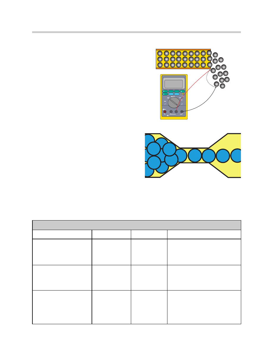
Ohms
The “Resistance” of a circuit opposes
current flow. The unit of measure for
resistance is the “Ohm”.
One ohm is defined as the amount of resis-
tance that will allow one amp to flow when
being pushed by one volt of pressure.
Resistance slows the flow of current (reduces
the number of electrons flowing).
Resistance changes electrical energy into
another form of energy (e.g. heat, light or
motion).
-
-
-
-
-
- -
- - -
- -
-
-
-
Resistance reduces the number
of electrons flowing
FLUKE 88
AUTOMOTIVE METER
ZERO
MIN MAX
RANGE
HOLD
H
SMOOTH
RPM
% DUTY
ALERT
Hz
ms-PULSE
+
_
TRIGGER
OFF
V
RPM
V
mV
mA
A
mA
A
A
mA
COM
V
10A MAX
FUSED
1000 MAX
Amps
_ _ _ _ _
_
_
_
_
_
_
_
_
_
_
_
_
_
_
_
_
_
_
_
_
_
_
_
_
_
_
_
_
_
_
_
_
_
_
_
Electrical Units of Measure
Unit of Measure
Symbol
Basic Unit
Units
Volt
V, U, or E
Volt
V = Volt = 1 volt
mV = millivolt = .001 volt
KV = Kilovolt = 1,000 volts
Ampere
Amp, A, or I
Amp
A = amp = 1 amp
mA = milliamp - .001 A
KA = Kiloamp = 1,000 A
Ohm
Ω
Ohm
1
Ω = 1 ohm
m
Ω = milliohm = .001 ohm
K = kilo-ohm = 1,000 ohms
M = Megaohm = 1,000,000 ohms
10
Basic Electricity
Circuits
Electricity must have a complete or closed loop circuit to flow. A “Circuit” is defined as
an unbroken, uninterrupted path which begins and ends at the same point. In the auto-
mobile that point is the battery. The electron flow must be from the battery through the
wiring and consumers back to the battery. That flow represents a complete circuit.
A typical circuit will contain:
1. A battery and/or generator system (EMF or source of the electrons)
2. Conductors (wiring to deliver the electrons to the consumers)
3. Consumers (the load being placed on the system)
Any break or interruption in this circuit will cause the circuit to cease operation.
There are three basic types of circuits:
• Series
• Parallel
• Series/Parallel
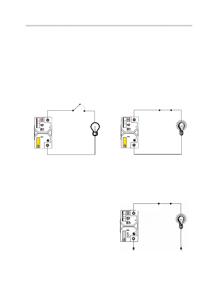
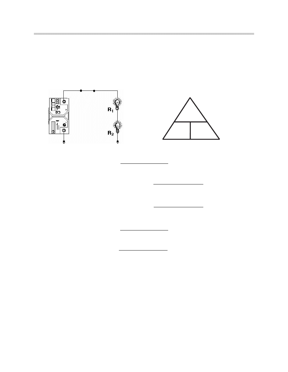
Series Circuit
A Series circuit provides one path for the current
flow. That path is from the source of the current
(the battery) through a conductor, consumer and
back to the source.
A Series circuit provides constant current flow
(amps) through the entire circuit. Amps measured
in any two places in the circuit will be equal.
RECYCLE
LEAD
RETURN
DANGER / POISON
SUFFICIENTL
Y CHARGED
INSUFFICIENTL
Y CHARGED
REPLACE BA
TTER
Y
Pb
RECYCLE
LEAD
RETURN
DANGER / POISON
SUFFICIENTL
Y CHARGED
INSUFFICIENTL
Y CHARGED
REPLACE BA
TTER
Y
Pb
Open Circuit
Complete/Closed Circuit
Series Circuit
Switch
Switch
Switch
11
Basic Electricity
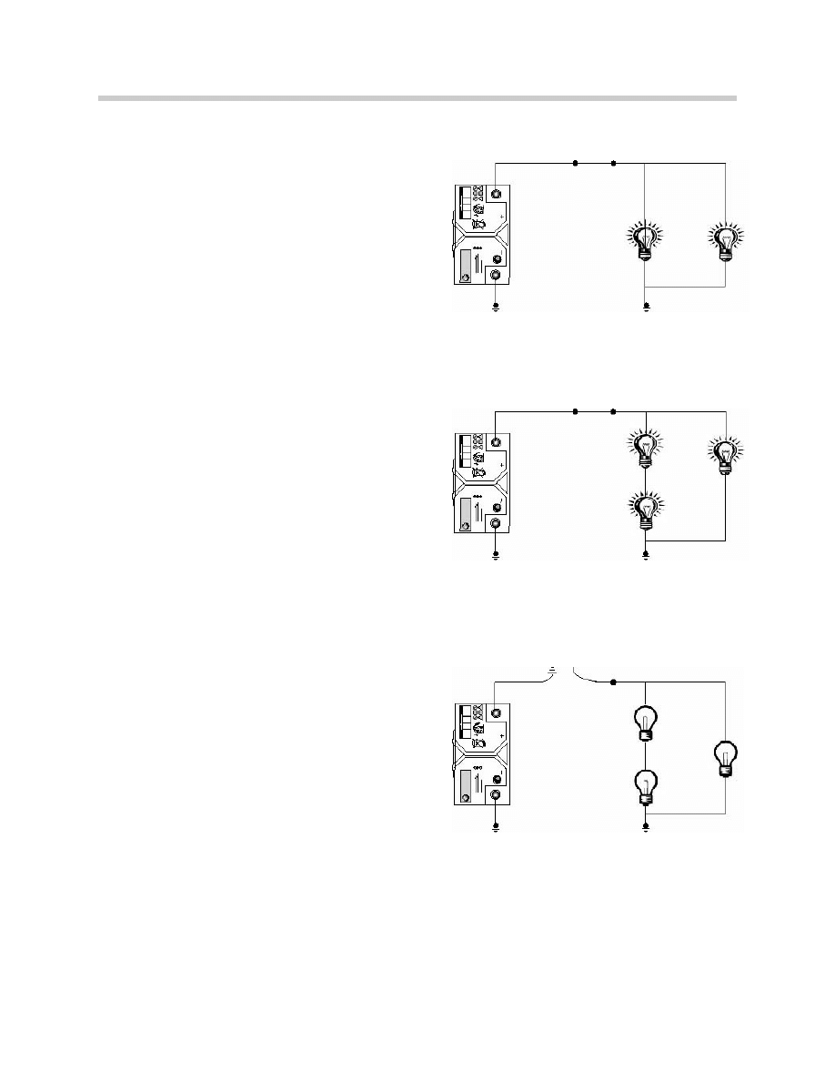
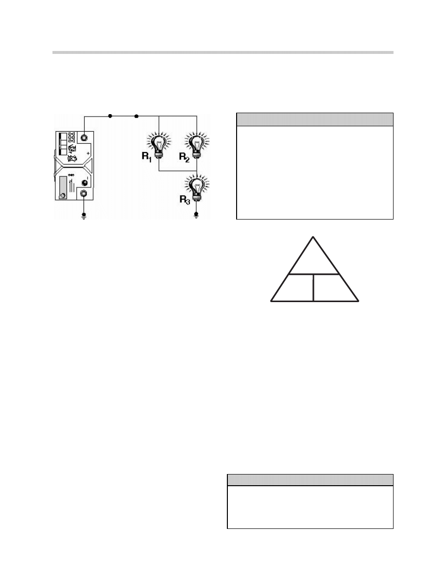
Parallel Circuit
A Parallel circuit provides multiple current paths.
In a Parallel circuit, all of the component’s posi-
tive terminals are connected to one point and
all of the component’s negative terminals are
connected to a different common point.
Source voltage is the same at all loads.
The current flow in a parallel circuit will be equal
to the sum of the current flowing through each
branch of the circuit.
Series-Parallel Circuit
A Series-Parallel circuit contains portions of the
current path that are in series with each other
and other portions of the path that are parallel
with each other. A headlight circuit would typi-
cally be this type of Series/Parallel circuit. The
headlight switch is in series with the headlights,
and the headlights are in parallel branches with
each other.
Short Circuit
Any damage to a circuit is classified as a
short circuit.
There are three types of common failures that
can occur in a circuit:
• Open circuit - break in the path of current
flow
• Short to ground - circuit grounded before
load
• Short to power - circuit path is exposed to
another source voltage
Switch
Switch
Short to Ground
12
Basic Electricity
Ohm’s Law
The key to intelligent troubleshooting of electrical circuits is a thorough understanding
of Ohm’s Law. Ohm’s Law states that the current flowing in a circuit varies directly with
the voltage and inversely with the resistance.
The pressure of one volt applied to one Ohm of resistance will cause one amp of
current to flow. If the voltage increases, current will increase. If resistance increases,
current will decrease.
Knowing any two of the three factors (volts, resistance or current) enables the third
factor to be calculated using Ohm’s Law.
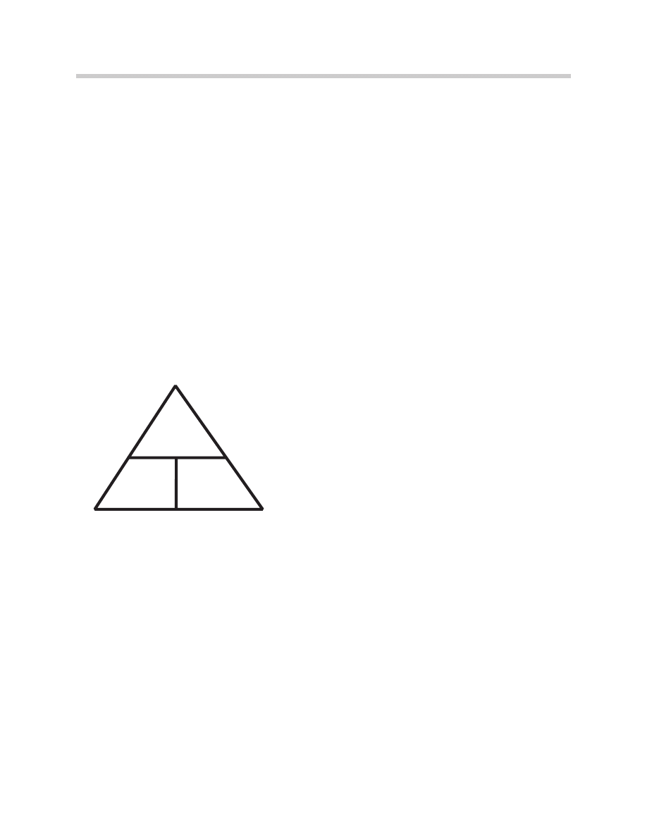
The mathematical expression is:
Volts = Resistance X Current
This formula is expressed in the Ohm’s Law Triangle.
To find a missing factor, insert the known
factors in the appropriate position and perform the math. A horizontal line between
two factors means to divide, a vertical line means multiply.
Understanding of Ohm’s Law is essential in the diagnosis of electrical problems. A
practical understanding of how the three factors affect each other is equally useful.
• Source voltage is not affected by current or resistance. It can only have three states.
Too low - Current flow will be low.
Too high - Current flow will also be too high.
Correct voltage - Current flow will be dependent on the resistance.
• Current Flow will be directly affected by either voltage or resistance.
High voltage or low resistance will cause an increase in current flow.
Low voltage or high resistance will cause a decrease in current flow.
• Resistance is not affected by either voltage or current. Resistance like source voltage
can have only three states.
Too low - current will be too high if the voltage is ok.
Too high - current flow will be low if the voltage is ok.
Correct resistance - current flow will be high or low, dependent on voltage.
V
I
R
V = Volts
I = Current or Amps (A)
R = Resistance (W)
Note: Voltage is sometimes expressed as U or E.
Ohm’s Law Triangle
13
Basic Electricity
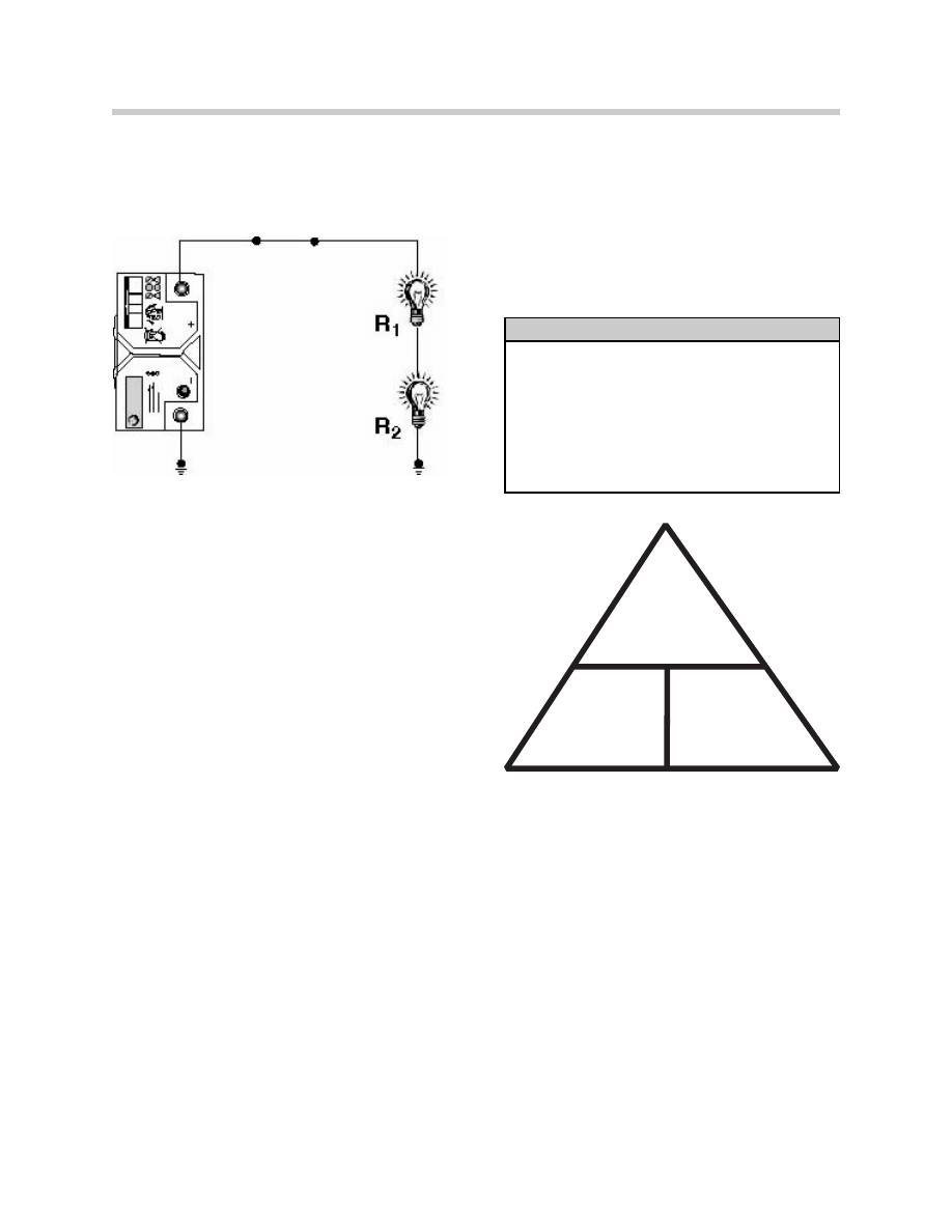
Ohm’s Law - Series Circuits
Applying Ohm’s Law in a series circuit requires simple math. The current has only one
path. Circuit resistance total is arrived at by adding the individual resistances. Amperage
is calculated by dividing source voltage by the total resistance.
R1 + R2 = Rt
V / Rt = A
Example:
If:
R1 = 2
Ω
R2 = 3
Ω
V = 12.0 volts
A = ?
To calculate total resistance.
Rt = R1
+
R2
Rt = 2 + 3
Rt = 5
Ω
Now that the total resistance is known, we can
calculate for the amperage.
A = V / Rt
A = 12 / 5
A = 2.4 Amps (I)
The total amperage can be used to calculate the expected voltage drop at each bulb?
A x R1 = voltage across bulb 1
A x R2 = voltage across bulb 2
2.4 x 2 = 4.8 volts
2.4 x 3 = 7.2 volts
If the two voltage drops are added, the result should be source voltage.
Voltage drop across bulb 1 + voltage drop across bulb 2 = source voltage
4.8 v + 7.2 v = 12 v
Key Features - Series Circuit
• Current through each load is the same.
• Total resistance equals the sum of the
individual resistances.
• Voltage drop across each load will be
different if the resistance is different.
• Total voltage drop equals source voltage.
V
I
R
Series Circuit
14
Basic Electricity
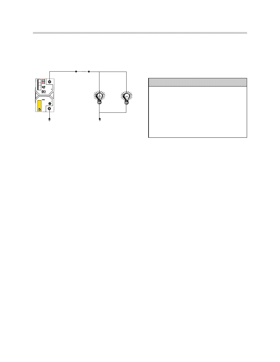
Ohm’s Law Parallel Circuit - 2 Branches
A Working in a Parallel circuit requires a little more math. Each branch of the circuit has
it’s own path to the voltage source. Before amps are calculated total circuit resistance
must be found.
Example 1:
If:
R1 = 3
Ω
R2 = 6
Ω
Voltage = 12.0 volts
The current for both branch R1 and R2 can be calculated using Ohm’s Law.
V / R1 = branch current
V / R2 = branch current
12 / 3 = 4 amps
12 / 6 = 2 amps
We can add the current flowing through each branch to determine the total amperage.
Amperage of branch 1 + Amperage of branch 2 = Total circuit current
4 a + 2 a = 6 amps
We can also calculate for the total resistance of the circuit.
Rt = (R1 x R2) / (R1 + R2)
Rt = ( 3 x 6 ) / ( 3 + 6 )
Rt = 2
Ω
Example 2:
If:
R1 = 6
Ω
R2 = 6
Ω
To calculate the total resistance in an parallel circuit with resistances that are the same
we could use the formula:
Rt = R
(either )
/ 2
Rt = 6 / 2
Rt = 3
Ω
Key Features - Parallel Circuit
• Current flow through each branch can be
different if the resistances are different.
• Total Resistance of the circuit is less than
the resistance of the lowest branch.
• Voltage drop across each branch circuit is
the same.
• Total current is the sum of the branches.
R
EC
YCLE
LEAD
RETURN
DANG
ER / PO
ISON
SUFFICIENTL
Y CHARG
ED
INSU
FFIC
IEN
TL
Y CHARG
ED
REPLACE BA
TTER
Y
Pb
R
R
1
2
Parallel Circuit
+
1
1 1 1 1
R1 R2 R3 R4
+
+
+
+
1 1 1 1
3 3 6 4
1
+
+
1
+
+
1
.92Ω
13
12
4 4 2 3
12 12 12 12
+
+
+
+
=
=
=
=
R
R
R
2
3
4
15
Basic Electricity
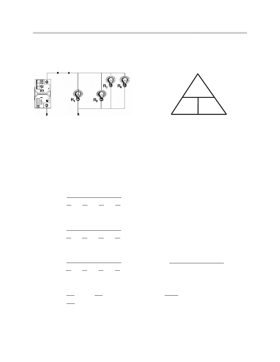
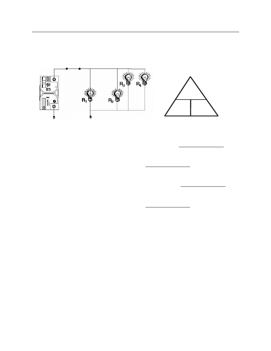
Ohm’s Law Parallel Circuit - more than 2 Branches
Calculating circuit resistance in a Parallel circuit with more than 2 branches is performed
by one of two methods. All the key features for a Parallel circuit still apply.
Example: 1
If:
R1 = 3
Ω
R2 = 3
Ω
R3 = 6
Ω
R4 = 4
Ω
To calculate the total resistance we can use the formula:
1
1
1
1
1
R1
R2
R3
R4
1
1
1
1
1
3
3
6
4
1
1
4
4
2
3
.33 + .33 + .167 + .25
12 12 12 12
1
12
1
13
13
1.08
12
Rt = .92
Ω
V
I
R
+
+
+
+
+
+
Rt =
Rt =
Rt =
Rt =
=
Rt =
Parallel Circuit
+
+
+
or
Rt =
or

16
Basic Electricity
Example: 2
If:
R1 = 3
Ω
R2 = 3
Ω
R3 = 6
Ω
R4 = 4
Ω
To calculate the total resistance we can use the formula
Rbr = (R1 x R2) / (R1 + R2)
to calculate the resistance of two branches at a time.
R
br1
= (R1 x R2) / (R1 + R2)
R
br1
= ( 3 x 3 ) / ( 3 + 3 )
R
br1
= 9 / 6
R
br1
=
1.5
Ω
R
br2
= (R
br1
x R3) / (R
br1
+ R3)
R
br2
= ( 1.5 x 6 ) / ( 1.5 + 6 )
R
br2
= 9 / 7.5
R
br2
=
1.2
Ω
R
t
= (R
br2
x R4) / (R
br2
+ R4)
R
t
= ( 1.2 x 4 ) / ( 1.2 + 4 )
R
t
= 4.8 / 5.2
R
t
= .
92
Ω
Either formula you choose to utilize to calculate total resistance in a parallel circuit that
has two or more branched will render the correct answer.
Please note that the following rules are still applicable all for this parallel circuits:
• Current flow through each branch can be different if the resistances are different.
• Total Resistance of the circuit is less than the resistance of the lowest branch.
• Voltage drop across each branch circuit is the same.
• Total current is the sum of the branches.
17
Basic Electricity
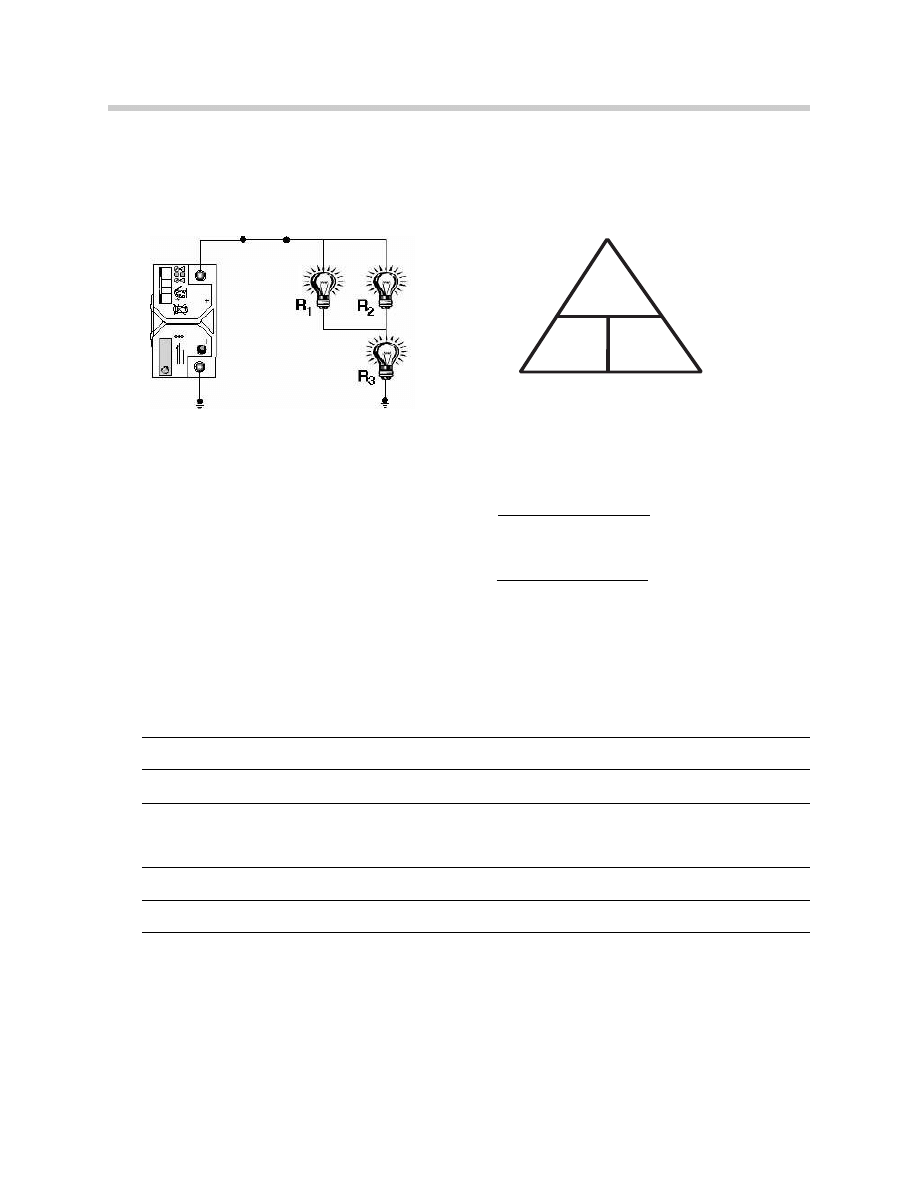
Ohm’s Law in Series-Parallel Circuit
When calculating resistance in a series-parallel circuit, always calculate the equivalent
resistance in the parallel portion of the circuit. Then add this resistance (equivalent resis-
tance) to the resistance of the series portion of the circuit.
Example: 1
If:
R1 = 4
Ω
R2 = 6
Ω
R3 = 2
Ω
Calculate the equivalent resistance value of R1 and R2.
Remember the resistance of a parallel circuit is lower than the lowest resistance in that
circuit. The resistance of this portion of the circuit must be lower than 4
Ω, the lowest
resistance.
R
parallel branch
= (R1 x R2) / (R1 + R2)
R
parallel branch
= ( 4 x 6 ) / ( 4 + 6 )
R
parallel branch
= 2.4
Ω
Now follow the rules of a Series circuit.
The total circuit resistance is equal to the sum of the individual resistances.
Rt = R
parallel branch
+ R3
Rt = 2.4
Ω
+ 2
Ω
Rt = 4.4
Ω
Key Features - Series-Parallel Circuit
• Current in the series portion of the circuit is
the same at any point of that portion.
• Total circuit resistance is the sum of the par-
allel branch equivalent resistance and the
series portion resistance.
• Voltage applied to the parallel branch is
source voltage minus any voltage drop across
loads wired in series to the parallel branch in
front of it in the circuit.
Find the current draw of each parallel branch, add
together to get the total current draw of the paral-
lel portion, then using ohms law find the resis-
tance of the parallel branch.
Series Parallel Circuit
V
I
R
Alternate Formula for equivalent resistance:
18
Basic Electricity
Worksheet
Calculate the missing value using Ohm’s Law:
Series Circuit
1. A = 2a,
V = 12v,
R =
2. R1 = 4
Ω,
R2 = 4
Ω,
V = 12v,
A =
3. R1 = 4
Ω,
R2 = 2
Ω,
A = 2a,
V =
4. V = 12v,
A = 6a,
R =
5. A = 3a,
R = 8
Ω,
V =
V
I
R
19
Basic Electricity
Calculate the missing value using Ohm’s Law:
Parallel circuit
6. R1 = 2,
R2 = 1,
R3 = 2,
R4 = 1,
Rt =
7. Using Rt from Question 6, V=12,
A =
8. R1 = 2,
R2 = 1,
R3 = 2,
R4 = 4,
Rt =
9. Using Rt from Question 8, V =12,
A =
V
I
R
20
Basic Electricity
Calculate the missing value using Ohm’s Law:
Series-Parallel Circuit
10. R1 = 2,
R2 = 4,
R3 = 2,
Rt =
11. Using Rt from Question 10, V =12, A =
12. If the resistance on any of the branches of the parallel portion of this circuit is
reduced:
How is the total resistance for the circuit affected?
How is the amperage affected?
V
I
R

21
Basic Electricity
Worksheet Calculations
22
Basic Electricity
Magnetic Theory
The usefulness of electricity is greatly expanded through magnetism. Magnetism
enables the existence of electric motors, generators, coils, relays, solenoids, transform-
ers, etc. Magnetism, like electricity, can’t be seen, weighed on a scale or measured with
a ruler. How it works and is put it to use can be understood.
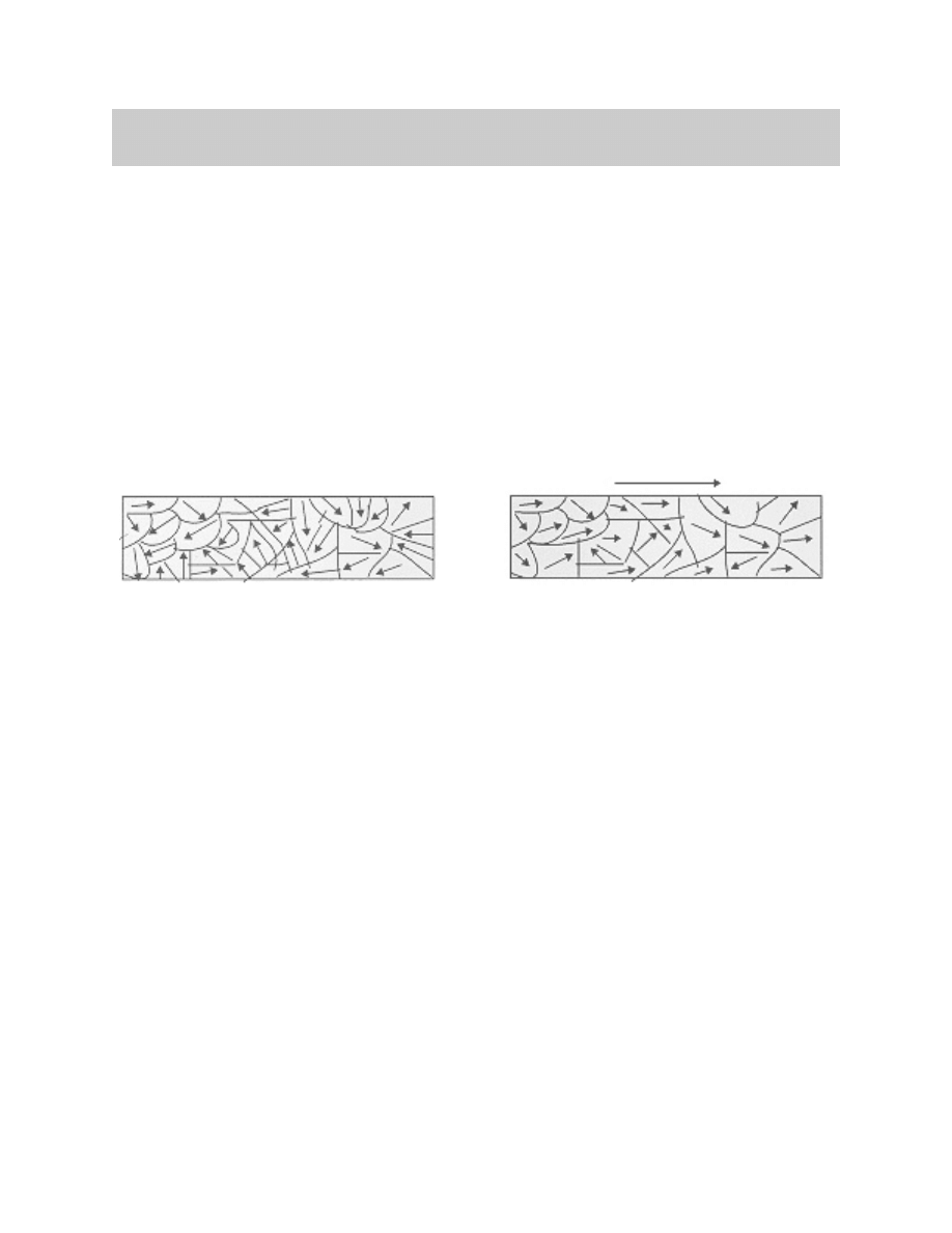
Two theories exist to explain how magnets work. The first theory states that a large quan-
tity of small magnetized particles exist in a magnet. If the item is not magnetized the par-
ticles are arranged in a random order. When the item becomes magnetized the particles
align with each other.
The second theory states that when the electrons of atoms are arranged in a certain
order, the circles of force of each atom combine creating the magnetism.
Fundamentals of Magnetism
• A magnet sets up a field of force.
• Magnetic lines of force form closed loops that flow from North to South.
• The space through which magnetic lines of force flow is called the magnetic field.
• The magnetic field is strongest closer to the magnet and becomes weaker as it
gets further away.
• Magnetic lines of force never cross each other.
• There is no known insulator against magnetism.
• Magnetic lines pass more easily through iron and steel than air.
• Opposing forces will occur at opposite ends of the magnet (Polarity). One end is the
North Pole (+), the opposite end is the South Pole (-).
• Like poles repel each other, unlike poles attract each other.
• Some materials (wood, ceramics, and some metals) cannot be magnetized.
Non Magnetized Iron Bar
Magnetic Iron Bar
Electrical Components
23
Basic Electricity
There are two common types of magnets:
• Permanent Magnets - made from materials such as hardened steel that become
magnetic when subjected to an outside magnetizing force and remain magnetic
even after the outside force has been removed.
• Temporary Magnets - made from materials such as soft iron that remain magnetic
only as long as an outside magnetic force is present.
The lines of force of all magnets, either per-
manent or temporary flow from the North
Pole of the magnet to the South Pole. The
magnetic lines of force or “flux” are stronger
closer to the magnet and get weaker as the
distance from the magnet increases. (Fig.
19/1)
Polarity refers to the opposing forces occur-
ring at opposite ends of the magnet. All
magnets have a North Pole and a South
Pole. Like poles will repel each other and
unlike poles will attract. (Fig.19/2)
Most temporary magnetic fields are pro-
duced by electricity flow. Whenever current
flows through a conductor magnetic lines of
force develop around the conductor.
These lines of force form a circular pattern.
The lines can be visualized as a magnetic
cylinder extending the entire length of the
conductor. (Fig.19/3)
The lines of force have direction and change dependent on direction of current flow.
The density of the lines of force are dependent on current flow through the conductor.
The greater the current flow, the stronger the magnetic field that will be around the con-
ductor.
N
S
N
S
N
S
N
S N
S
Curr
ent Flow
Fig.19/1
Fig.19/2
Fig.19/3
24
Basic Electricity
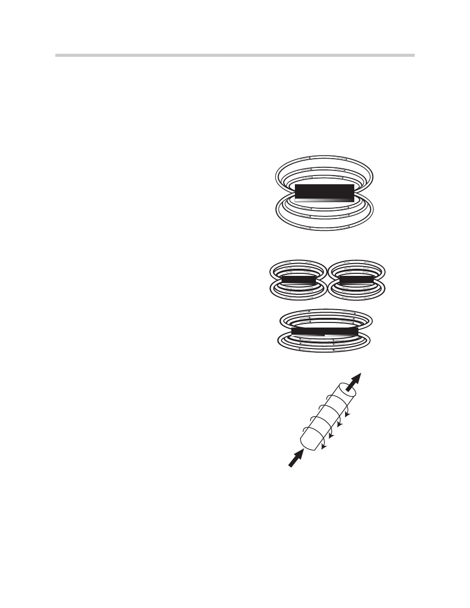
Passing a current flow through a conductor will not generate a magnetic field strong
enough to perform any work.
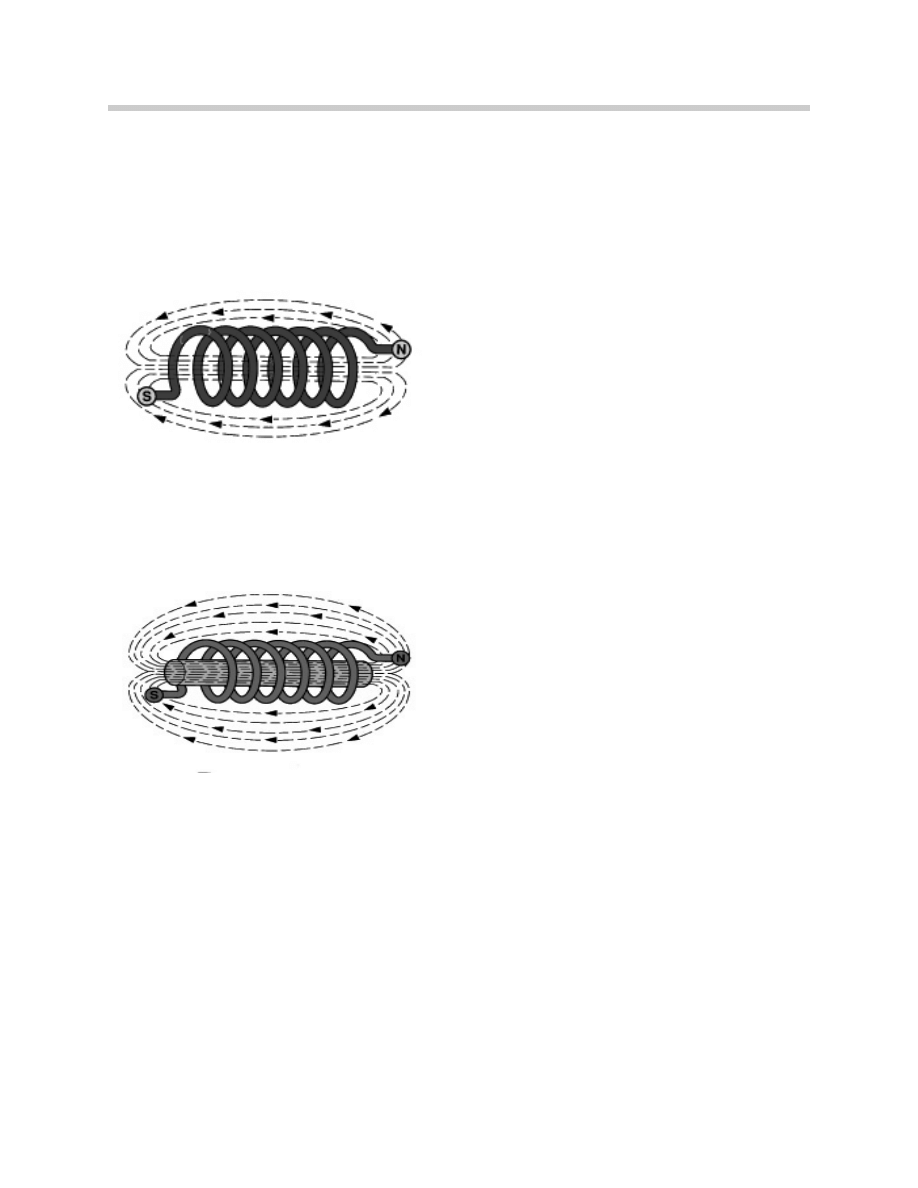
If the conductor is coiled, the lines of force combine and become more dense forming a
stronger field (Fig.20/1).
The greater the number of turns of the conductor or the stronger the current flowing
through the conductor the the stronger the magnetic field.
Inserting an iron core in the coiled conductor increases the magnetic field even more as
iron makes a better path for the magnetic lines than air (Fig.20/2).
This conductor wound around an iron bar is an “Electromagnet”. A coil with an air core is
a “Solenoid”.
Electromagnetic Induction
Producing a magnetic field by flowing current through a conductor is a process that can
be reversed. A magnetic field can be set up that will cause current to flow in a conductor.
This is called inducing or generating electricity by magnetism.
To induce voltage in a conductor it is necessary to have relative motion between the con-
ductor and the magnetic field. This motion can be in any one of three forms:
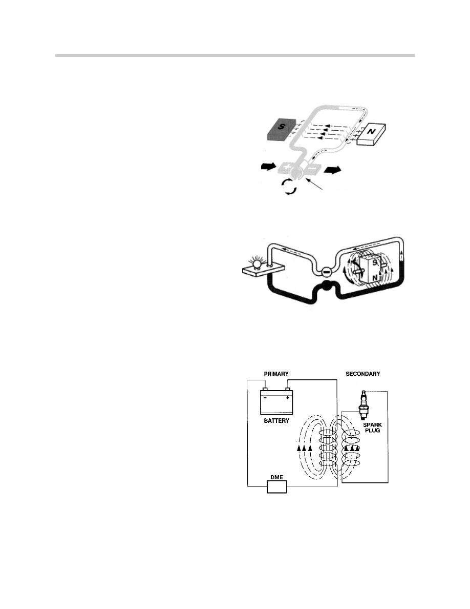
• The conductor moves or rotates in a stationary magnetic field as in a DC Generator.
• The magnetic field rotates in a stationary conductor producing voltage in the circuit
as in an AC Generator or Alternator.
• The building or collapsing of a magnetic field across a stationary conductor, as in an
Ignition Coil.
Fig.20/1
Fig.20/2
25
Basic Electricity
Generating Voltage
Generator
In a generator, the conductor moves through
a stationary magnetic field inducing voltage
at the commutator, which connects to the
circuit through brushes.
The voltage induced is direct current.
Alternator
In an alternator the magnetic field moves
(rotates) through the stationary conductor
producing voltage in the circuit.
The voltage induced is alternating current.
Ignition Coil
Voltage can be induced by the building or
collapsing of a magnetic field across a
stationary conductor.
B+ power is supplied by the battery and a
magnetic field is set up around the coiled
conductor. The DME grounds or pulls low
the current from the conductor and the loss
of current causes the magnetic field to
collapse inducing voltage in the secondary
conductor.
Commutator
26
Basic Electricity
Types of Voltage
DC Voltage
A flow of current that moves continuously in
one direction from a point of high potential
to a point of low potential is referred to as
DC (Direct Current).
Most automotive circuits operate on DC
voltage as supplied by the battery(s).
AC Voltage
Current which reverses its direction at
regular intervals is called AC (Alternating
Current).
This regular and continuous reversal of
current flow (cycle) occurs many times per
second.
AC voltage as produced by an automotive
alternator must be changed to direct current
so that the battery can be charged.
Conductors, Insulators and Semi-Conductors
Electrical properties of various materials are determined by the number of electrons in
the outer ring of their atoms.
Conductors
Materials with 1-3 electrons in the atoms
outer ring make it easy for electrons to move
from atom to atom. Remember that the def-
inition of current flow is the movement of
free electrons from one atom to another.
The electrons in the outer ring of these con-
ductors are loosely held and even a low
EMF will cause the flow of free electrons.
Many metals are good conductors, especial-
ly gold, silver, copper, and aluminum. But
not all conductors have the same amount of
resistance to the flow of free electrons.
Memory
-16
-12
-8
-4
0
4
8
12
16
0
-50
50
100
-100
-150
150
200
250
300
-200
-250
-300
A MV
0
0
4
40
8
80
12
120
16
160
-4
-40
-8
-80
-12
-120
-16
-160
Cursor1
Cursor2
BVmV
T
R
I
G
G
E
R
L
E
V
E
L
Holdscr
een
ChannelB
Zoom
Amplitude
ChannelA
Amplitude
ChannelB
Timevalue
Stimulate
Change
End
Services
Multimeter
Counter
Oscilloscope
setting
StimulatorsPreset
Meaurements
Help
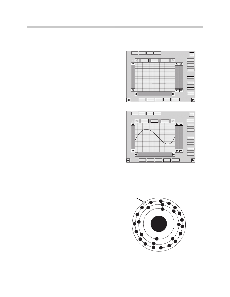
BMW Measuring System Oscilloscope Display
Memory
-16
-12
-8
-4
0
4
8
12
16
0
-50
50
100
-100
-150
150
200
250
300
-200
-250
-300
A MV
0
0
4
40
8
80
12
120
16
160
-4
-40
-8
-80
-12
-120
-16
-160
Cursor1
Cursor2
BVmV
T
R
I
G
G
E
R
L
E
V
E
L
Holdscr
een
ChannelB
Zoom
Amplitude
ChannelA
Amplitude
ChannelB
Timevalue
Stimulate
Change
End
Services
Multimeter
Counter
Oscilloscope
setting
StimulatorsPreset
Meaurements
Help
BMW Measuring System Oscilloscope Display
Conductor
27
Basic Electricity
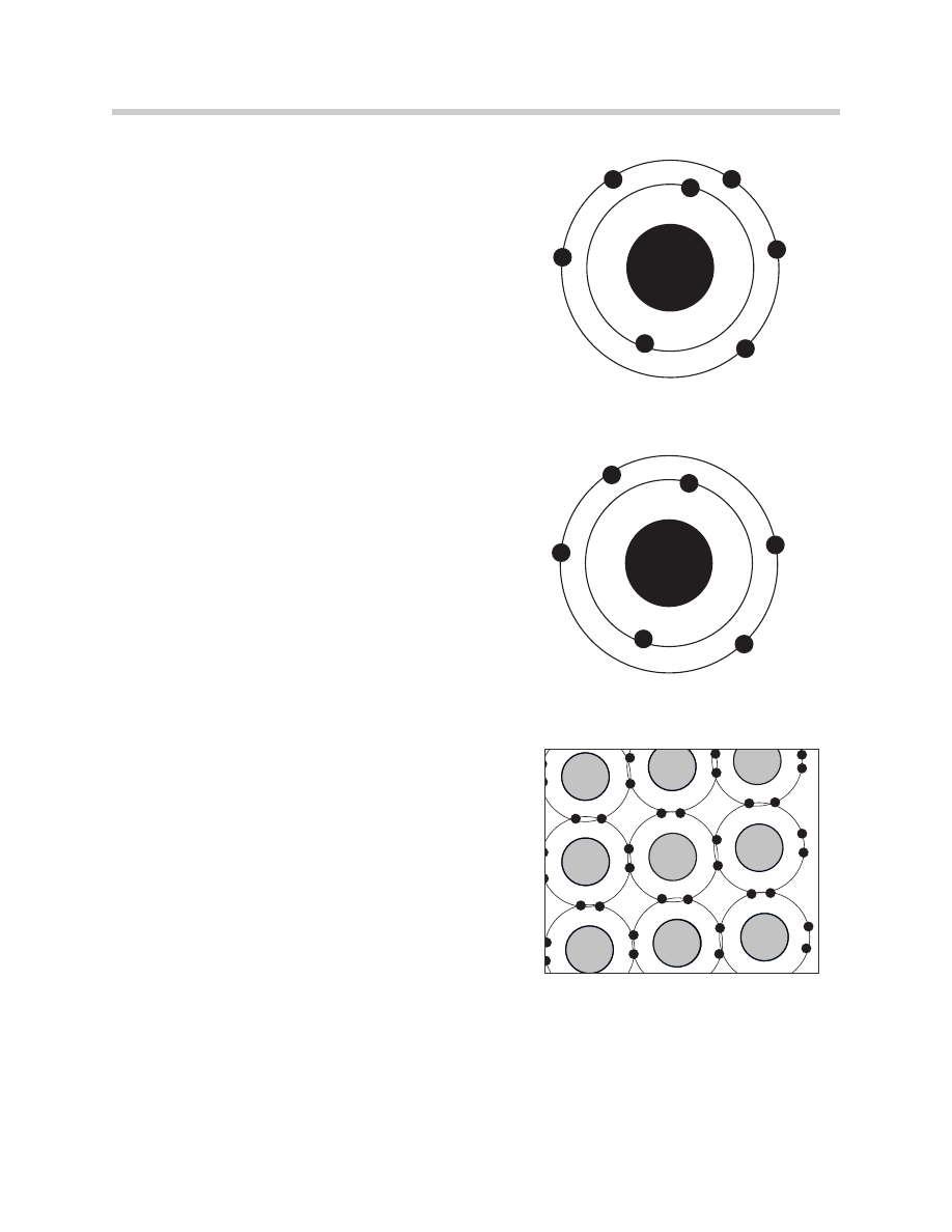
Insulators
Materials with 5-8 electrons in their outer ring
have those electrons bound tightly. These
materials are insulators (Poor conductors).
The electrons in the outer rings resist move-
ment, the atoms don’t give up the electrons
easily or accept free electrons easily.
This effectively stops the flow of free electrons
and thus any electrical current.
Materials such as rubber, glass, and certain
plastics are examples of good insulators.
Semi-Conductors
Materials with exactly 4 electrons in the atoms
outer ring are neither conductors nor insulators.
The 4 electrons in the outer ring cause special
electrical properties which give them the name
“Semi-Conductor”.
Materials such as Germanium and Silicone are
are two widely used semi-conductors.
Semi-Conductor Doping
When semi-conductors are in the form of a
crystal, the four electrons of the outer ring are
shared with a neighboring atom.
This makes the crystal form of these materials
an excellent insulator because there are no free
electrons to carry a current flow.
Insulator
Semiconductor
Semiconductor Insulator
28
Basic Electricity
Other elements (Impurities) can be added to change the crystalline structure of the
Germanium and Silicone.
This is called Doping of the semi-conductors. Doping creates free electrons or holes
enabling the semi-conductor to carry current.
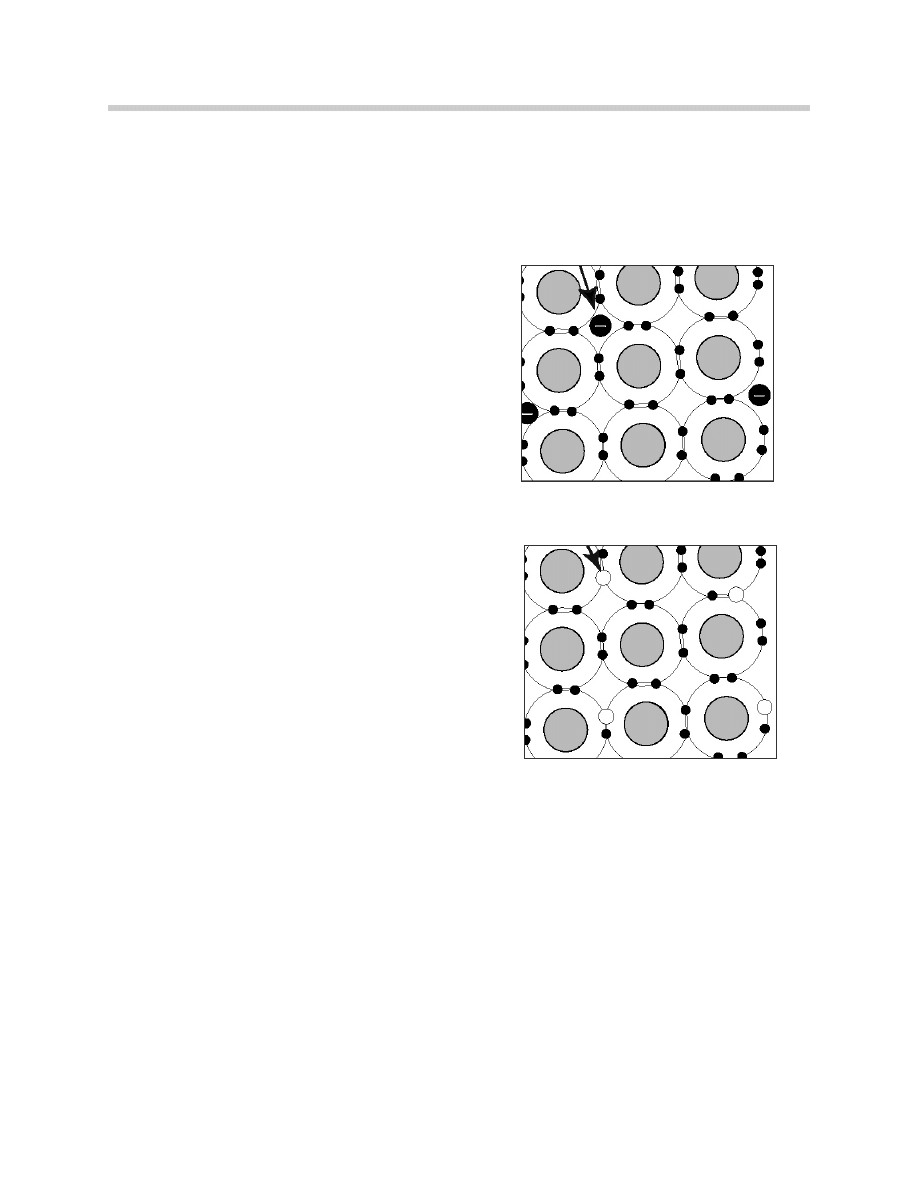
N-Type Material
If the semi-conductor is doped with an element
having 5 electrons in its outer ring there will not
be enough space in the outer ring for the 9th
electron (4 electrons in the semi-conductor and
5 in the impurity).
This type of doped material is called negative or
N-material, because it already has excess elec-
trons and will repel additional negative charges.
P-Type Material
If the semi-conductor is doped with an element
having 3 electrons in its outer ring some of the
atoms will only have 7 electrons in the outer
ring. There will be a hole in some of the outer
rings.
This type of doped material is called positive or
P-material because it will attract free electrons.
Junctions
Doping Germanium and Silicone cause them to behave in unusual but predictable ways
when exposed to voltage, depending on which charge of the voltage is connected to
which type of material (P or N).
The line along which joined P and N material meet is called the Junction. A simple
component consisting of P-material and N-material joined at a junction is called a diode.
The application of voltage to the two doped semiconductor materials is called biasing.
A more complex material containing two PN junctions is called a Transistor.
Free Electrons
N - Material
Holes
P-Material
29
Basic Electricity
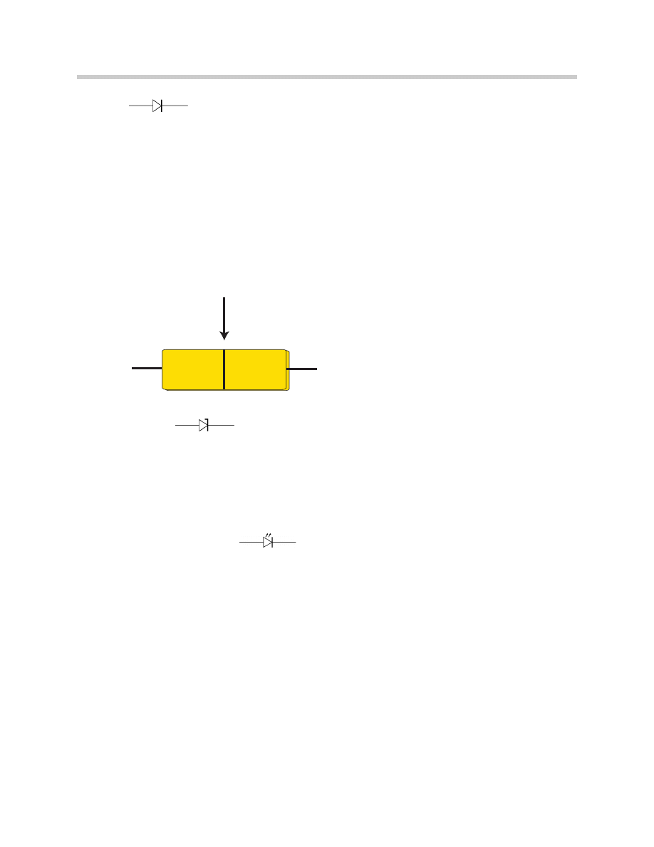
Diode
When N and P-type semiconductor materials are joined together to form a single crystal a
Diode is created. The diode allows electron flow in one direction only.
A diode has a forward bias when the Anode (P-material) is connected to B+ and the
Cathode (N-material) is connected to B-.
Reversing the source voltage on the diode will result in current flow stoppage. This is
called reverse bias.
Diodes are rated for specific voltage and current flow. The diode can not withstand
unlimited forward bias and current flow.
Zener Diode
A diode which will allow a specified amount of reverse flow current is called a Zener
Diode. If the breakdown voltage of the zener diode is 6 volts, at 6 volts and above the
zener diode will allow reverse current flow with no damage to the diode.
Below the breakdown voltage the zener diode will function as a normal diode and allow
current flow in only one direction.
Light Emitting Diode
Zener diodes are often used in charging systems to rectify or convert AC current to DC.
Like the diode, zener diodes are rated for specific voltage, current and reverse current.
Light-Emitting Diodes (LED) emit visible light when forward biased. As current flows
through the diode, electrical energy is converted into visible light that is radiated through
the thin positive material layer in the diode.
P
N
PN Junction
Anode
Cathode
30
Basic Electricity
Transistors
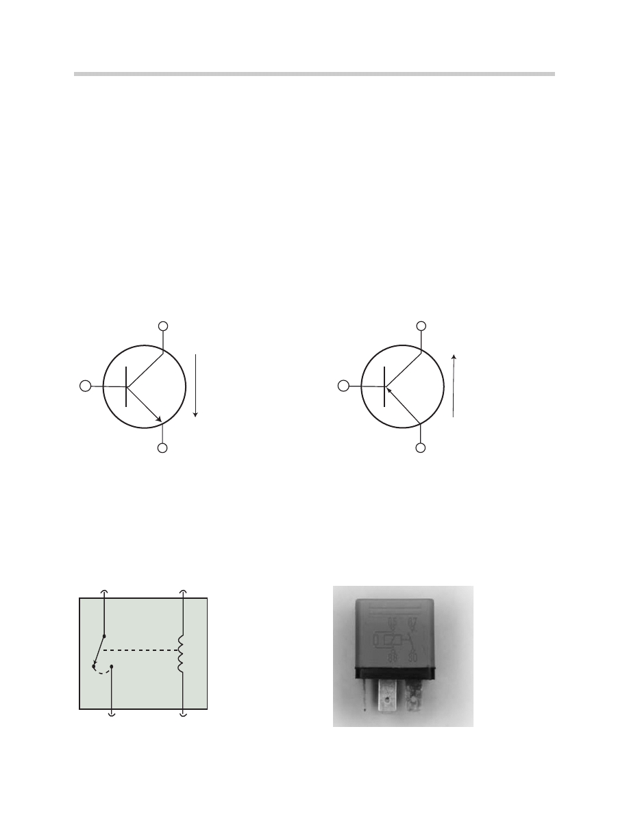
The Transistor is a diode with some additional semiconductor material. The transistor
contains two PN junctions, compared to one in a diode.
Transistors can be constructed in two ways: the P section can be sandwiched between
two N sections forming a NPN transistor, or the N section sandwiched between two P
sections forming a PNP transistor.
The three sections of the transistor are called the Emitter, the Base and the Collector.
Current applied to the base will flow through the transistor. Current flows through the NPN
in one direction and through the PNP in the opposite direction.
Transistors are used to control current flow, act as a switch or as an amplifier to vary the
current output dependent on base voltage variations.
A transistor allows control of large currents with small current signals.
Relays
A Relay is a switch that uses electromagnetism to physically move the contacts.
A small of amount of current flow through a relay coil moves an armature and opens or
closes a set of points.
The points control the flow of a larger amount of current through a separate circuit.
Collector
Base
Emitter
NPN Transistor
Curr
ent
Collector
Base
Emitter
PNP Transistor
Curr
ent
30
86
87
85
NPN Transistor
PNP Transistor
31
Basic Electricity
Think of the two sides of a relay independently.
• Control side: Which includes the B+(KL86) and B-(KL85) for the coil that creates the
magnetic force. If this side of the relay fails open the work side points will remain in
their at rest position.
• Work side: Which includes the B+ input power (KL30) and the Relay output (KL87).
Failure of this side of the relay in the closed position (sticking points) will result in
constant current flow.
BMW uses relays with various numbers of pins (3,4,5 pin) and pin configurations (normal-
ly open, normally closed and changeover type). Do not substitute relays. Always
replace with the same type (e.g. DME Main Power Relay, Secondary Air Pump Relay
and Rear Window Defroster Relay.).
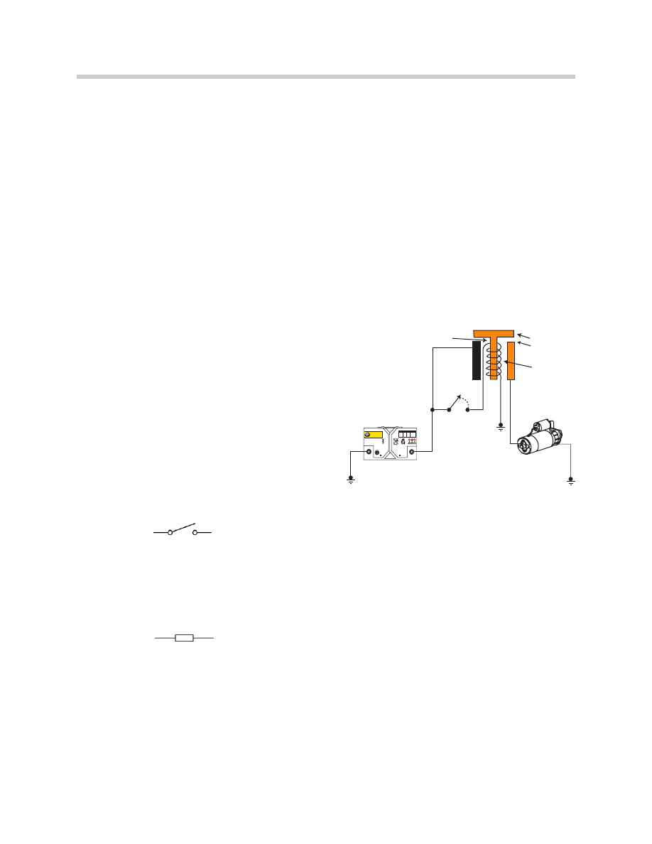
Solenoids
A Solenoid, like a relay, uses current flow and
electromagnetism to produce mechanical
movement. Solenoids consist of a coil winding
around a spring loaded metallic plunger.
When current flows through the winding, the
magnetic field attracts the movable plunger,
pulling it against spring pressure into the center
of the coil. When current flow stops, the mag-
netic field collapses and the plunger is moved
out of the coil by spring pressure.
Solenoids are commonly used in starter
motors, injectors and purge valves.
Switches
A Switch is a mechanical device used to start, stop or redirect current flow. A switch can
be installed on the positive side of the circuit or the negative side of the circuit. A switch
can be used to to control a load device directly or used to operate a relay which in turn
can operate a higher current device. (e.g. Headlight switch, Horn button and Window
switch.)
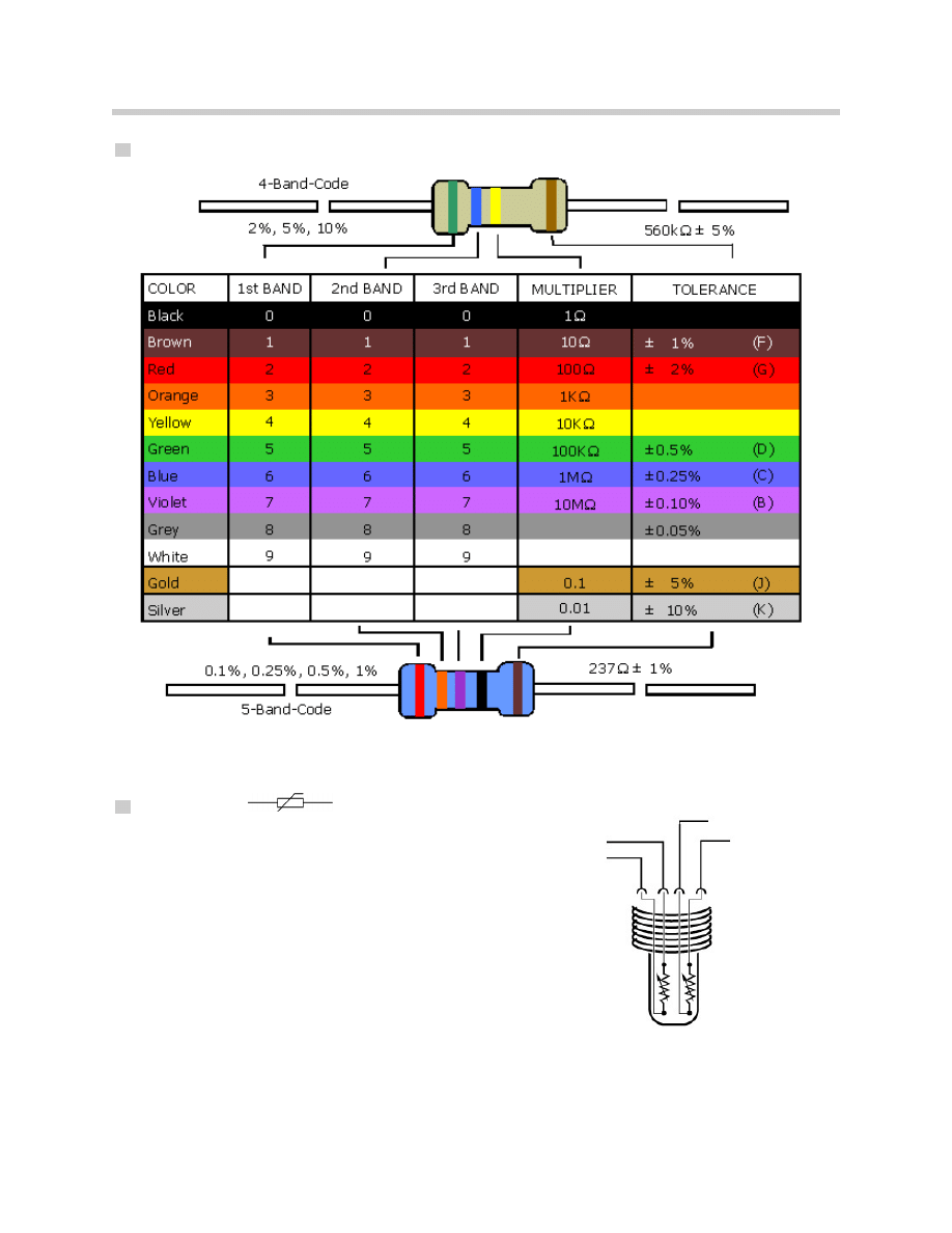
Resistors
Resistors limit the current flow in a circuit. The resistor is used in a circuit to introduce a
desired amount of resistance into the circuit.
Resistors are available in fixed resistance or variable resistance. Fixed resistors are color
coded to indicate their resistance.
RECYCLE
LE
AD
RETURN
DANGER / POISON
SUFFICIENTL
Y CHARGED
INSUFFICIENTL
Y CHARGED
REPLACE BA
TTER
Y
Pb
Power
Source
Starter
Motor
Switch
Coil
Contacts
Solenoid
Core
(Armature)
Starter Solenoid Circuit
32
Basic Electricity
Resistor Color Code Guide
Variable Resistors
Thermistor
The resistance of materials can vary with
changes in temperature; therefore, resistors can
have a changing resistance value dependent on
temperature.
A Thermistor is a resistor that can achieve large
changes in resistance with small changes in
temperature.
Thermistors are normally of the NTC (negative
temperature coefficient) type. As the tempera-
ture increases the resistance decreases.
Engine Temp Dual Thermistor
33
Basic Electricity
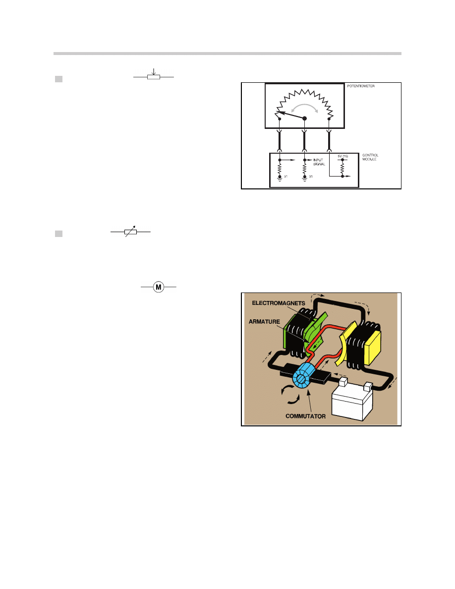
Potentiometer
A Potentiometer (pot) is a variable resistor capa-
ble of changing resistance values.
Potentiometers have three terminals. One of
the terminals is supply voltage, usually 5 volts.
One of the terminals is the control module
ground, and the third terminal is for the input
signal into the control module. (Output from
the Pot.)
Potentiometers are used to measure mechani-
cal movement. (e.g. EDR feedback)
Rheostat
A Rheostat is similar in operation to a potentiometer except a Rheostat only has two con-
nectors. This arrangement allows the resistance to be varied between those two connec-
tors.
Electric Motors
DC motors are similar to DC generators. They
may be described as generators run backwards.
When current is passed through the armature
of a DC motor, a torque is generated by mag-
netic reaction and the armature revolves.
Stepper Motors
Stepper Motors behave differently than standard DC motors. Unlike DC motors which
spin freely when power is applied, stepper motors do as their name suggests, they step
or rotate incrementally a little bit at a time. While DC motors need higher speeds to pro-
duce higher torque, stepper motors provide their highest torque at their slowest speeds.
Stepper motors also have holding torque, the ability to resist movement by outside forces.
Steppers are driven by the interaction (attraction and repulsion) of magnetic fields. The
driving magnetic field rotates as strategically placed coils are switched on and off. This
pushes and pulls at permanent magnets arranged around the rotor that drive the output
shaft.
Potentiometer

34
Basic Electricity
Common Circuit Designations
NAME
CIRCUIT
B+
Battery Positive
B-
Battery Negative
KL
Standardized Abbreviation for Clamp or Terminal Number
KLO
Ignition Switch Off
KLR
Voltage Ignition Switch in ACC, Run Start
Hot in Acc/ Run/ Start
KL15
Voltage Ignition Switch in Run and Start
Hot (12v) in Run/ Start
KL15U/15i
Voltage Ignition Switch in Run
Hot (12v) in Run
KL30
12v At All Times (Relay Work Power)
Hot (12v) All Times
KL30H
Starter Signal
KL50
Voltage Ignition Switch in Start
Hot (12v) in Start
KL58
Interior Lighting Dimmer Signal
KL61
Ground with Alternator Output, 12v with KL15
85
Relay Coil Ground (Signal) control side
86
Relay Coil B+ Control Side
87
Relay Output Work Side
87a
Relay Output Work Side At Rest
35
Basic Electricity
Review Questions
1. Electrons orbit around a nucleus of what materials?
2. Why are some atoms referred to “Negative Ions” and where to do they collect?
3. Where do the “free” electrons come from and how are they freed?
4. Describe the flow of electrons using the “Theory of Electron Flow”
5. An increase in the number of negative ions collecting at the negative battery
post will have what effect on the “potential of electrons” to flow?
6. Name three things a complete circuit will contain?
7. Describe how current flow will be affected by voltage and/or resistance.
8. What affect will increasing current flow have on the magnetic field around a
conductor?
9. Name the three forms of motion used to induce voltage in a conductor.
10. What will happen to current, if a diode is installed in a forward bias?
11. What happens to the resistance of an NTC type variable resistor if the
temperature is decreased?
12. What type of motor can be used to hold something still?
13. What is Doping of semiconductors?
14. Why can’t electrons move about freely in an insulator?
36
Basic Electricity
Document Outline
- Main Menu
- Basic Electricity
- The DVOM
- Breakout Boxes & Connectors
- Understanding Diagnostics
- EWS
- Electronic Signals
- The Battery
- Charging Systems
- Starting Systems
- Introduction to Bus Systems
- E65 Power Management
- E65 Power Module
- E65 Car Access System
- E6x Power Supply and Bus Systems
Wyszukiwarka
Podobne podstrony:
więcej podobnych podstron