Data sheet
6ES7314-6CG03-0AB0
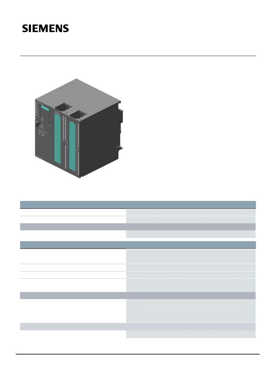
***Spare part*** SIMATIC S7-300, CPU 314C-2 DP Compact CPU
with MPI, 24 DI/16 DO, 4 AI, 2 AO, 1 Pt100, 4 high-speed counters
(60 kHz), integrated DP interface, Integr. power supply 24 V DC,
Work memory 96 KB, Front connector (2x 40-pole) and Micro
Memory Card required
General information
HW functional status
01
Firmware version
V2.6
Engineering with
● Programming package
STEP 7 V5.3 SP2 or higher with HW update
Supply voltage
Rated value (DC)
● 24 V DC
Yes
permissible range, lower limit (DC)
20.4 V
permissible range, upper limit (DC)
28.8 V
external protection for power supply lines
(recommendation)
Miniature circuit breaker, type C; min. 2 A; miniature circuit
breaker type B, min. 4 A
Load voltage L+
● Rated value (DC)
24 V
● permissible range, lower limit (DC)
20.4 V
● permissible range, upper limit (DC)
28.8 V
Digital inputs
— Rated value (DC)
24 V
6ES7314-6CG03-0AB0
Subject to change without notice
Page 1/16
08/20/2018
© Copyright Siemens
— Reverse polarity protection
Yes
Digital outputs
— Rated value (DC)
24 V
— Reverse polarity protection
No
Analog outputs
— Rated value (DC)
24 V
— Reverse polarity protection
Yes
Input current
Current consumption (rated value)
1 000 mA
Current consumption (in no-load operation), typ.
150 mA
Inrush current, typ.
11 A
I²t
0.7 A²·s
Digital inputs
● from load voltage L+ (without load), max.
70 mA
Digital outputs
● from load voltage L+, max.
100 mA
Power loss
Power loss, typ.
14 W
Memory
Work memory
● integrated
96 kbyte
● expandable
No
Load memory
● Plug-in (MMC)
Yes
● Plug-in (MMC), max.
8 Mbyte
● Data management on MMC (after last
programming), min.
10 y
Backup
● present
Yes; Guaranteed by MMC (maintenance-free)
● without battery
Yes; Program and data
CPU processing times
for bit operations, typ.
0.1 µs
for word operations, typ.
0.2 µs
for fixed point arithmetic, typ.
2 µs
for floating point arithmetic, typ.
3 µs
CPU-blocks
Number of blocks (total)
1 024; (DBs, FCs, FBs); the maximum number of loadable blocks
can be reduced by the MMC used.
DB
● Number, max.
511; Number range: 1 to 511
6ES7314-6CG03-0AB0
Subject to change without notice
Page 2/16
08/20/2018
© Copyright Siemens

● Size, max.
16 kbyte
FB
● Number, max.
1 024; Number range: 0 to 2047
● Size, max.
16 kbyte
FC
● Number, max.
1 024; Number range: 0 to 2047
● Size, max.
16 kbyte
OB
● Size, max.
16 kbyte
● Number of free cycle OBs
1; OB 1
● Number of time alarm OBs
1; OB 10
● Number of delay alarm OBs
1; OB 20
● Number of cyclic interrupt OBs
1; OB 35
● Number of process alarm OBs
1; OB 40
● Number of DPV1 alarm OBs
3; OB 55, 56, 57
● Number of startup OBs
1; OB 100
● Number of asynchronous error OBs
5; OB 80, 82, 85, 86, 87
● Number of synchronous error OBs
2; OB 121, 122
Nesting depth
● per priority class
8
● additional within an error OB
4
Counters, timers and their retentivity
S7 counter
● Number
256
Retentivity
— adjustable
Yes
— lower limit
0
— upper limit
255
— preset
8
Counting range
— lower limit
0
— upper limit
999
IEC counter
● present
Yes
● Type
SFB
● Number
Unlimited (limited only by RAM capacity)
S7 times
● Number
256
Retentivity
— adjustable
Yes
— lower limit
0
6ES7314-6CG03-0AB0
Subject to change without notice
Page 3/16
08/20/2018
© Copyright Siemens
— upper limit
255
— preset
No retentivity
Time range
— lower limit
10 ms
— upper limit
9 990 s
IEC timer
● present
Yes
● Type
SFB
● Number
Unlimited (limited only by RAM capacity)
Data areas and their retentivity
retentive data area in total
All, max. 64 KB
Flag
● Number, max.
256 byte
● Retentivity available
Yes; MB 0 to MB 255
● Retentivity preset
MB 0 to MB 15
● Number of clock memories
8; 1 memory byte
Data blocks
● Retentivity adjustable
Yes; via non-retain property on DB
● Retentivity preset
Yes
Local data
● per priority class, max.
510 byte
Address area
I/O address area
● Inputs
1 kbyte
● Outputs
1 kbyte
of which distributed
— Inputs
979 byte
— Outputs
986 byte
Process image
● Inputs
128 byte
● Outputs
128 byte
Default addresses of the integrated channels
— Digital inputs
124.0 to 126.7
— Digital outputs
124.0 to 125.7
— Analog inputs
752 to 761
— Analog outputs
752 to 755
Digital channels
● Inputs
7 856
— of which central
1 016
● Outputs
7 904
— of which central
1 008
6ES7314-6CG03-0AB0
Subject to change without notice
Page 4/16
08/20/2018
© Copyright Siemens

Analog channels
● Inputs
494
— of which central
253
● Outputs
495
— of which central
250
Hardware configuration
Number of expansion units, max.
3
Number of DP masters
● integrated
1
● via CP
4
Number of operable FMs and CPs (recommended)
● FM
8
● CP, PtP
8
● CP, LAN
10
Rack
● Racks, max.
4
● Modules per rack, max.
8; In rack 3 max. 7
Time of day
Clock
● Hardware clock (real-time)
Yes
● retentive and synchronizable
Yes
● Backup time
6 wk; At 40 °C ambient temperature
● Deviation per day, max.
10 s
Operating hours counter
● Number
1
● Number/Number range
0
● Range of values
0 to 2^31 hours (when using SFC 101)
● Granularity
1 h
● retentive
Yes; Must be restarted at each restart
Clock synchronization
● supported
Yes
● to MPI, master
Yes
● to MPI, slave
Yes
● to DP, master
Yes; With DP slave only slave clock
● to DP, slave
Yes
● in AS, master
Yes
Digital inputs
Number of digital inputs
24
● of which inputs usable for technological
functions
16
integrated channels (DI)
24
6ES7314-6CG03-0AB0
Subject to change without notice
Page 5/16
08/20/2018
© Copyright Siemens
Input characteristic curve in accordance with IEC
61131, type 1
Yes
Number of simultaneously controllable inputs
horizontal installation
— up to 40 °C, max.
24
— up to 60 °C, max.
12
vertical installation
— up to 40 °C, max.
12
Input voltage
● Rated value (DC)
24 V
● for signal "0"
-3 to +5V
● for signal "1"
+15 to +30V
Input current
● for signal "1", typ.
9 mA
Input delay (for rated value of input voltage)
for standard inputs
— parameterizable
Yes; 0.1 / 0.3 / 3 / 15 ms
— Rated value
3 ms
for technological functions
— at "0" to "1", max.
8 µs
Cable length
● shielded, max.
1 000 m; 50 m for technological functions
● unshielded, max.
600 m; For technological functions: No
for technological functions
— shielded, max.
50 m
— unshielded, max.
not allowed
Digital outputs
Number of digital outputs
16
● of which high-speed outputs
4
integrated channels (DO)
16
Short-circuit protection
Yes; Clocked electronically
● Response threshold, typ.
1 A
Limitation of inductive shutdown voltage to
L+ (-48 V)
Controlling a digital input
Yes
Switching capacity of the outputs
● on lamp load, max.
5 W
Load resistance range
● lower limit
48 Ω
● upper limit
4 kΩ
Output voltage
● for signal "1", min.
L+ (-0.8 V)
Output current
6ES7314-6CG03-0AB0
Subject to change without notice
Page 6/16
08/20/2018
© Copyright Siemens
● for signal "1" rated value
500 mA
● for signal "1" permissible range, min.
5 mA
● for signal "1" permissible range, max.
0.6 A
● for signal "1" minimum load current
5 mA
● for signal "0" residual current, max.
0.5 mA
Parallel switching of two outputs
● for uprating
No
● for redundant control of a load
Yes
Switching frequency
● with resistive load, max.
100 Hz
● with inductive load, max.
0.5 Hz
● on lamp load, max.
100 Hz
● of the pulse outputs, with resistive load, max.
2.5 kHz
Total current of the outputs (per group)
horizontal installation
— up to 40 °C, max.
3 A
— up to 60 °C, max.
2 A
vertical installation
— up to 40 °C, max.
2 A
Cable length
● shielded, max.
1 000 m
● unshielded, max.
600 m
Analog inputs
Number of analog inputs
● For voltage/current measurement
4
● For resistance/resistance thermometer
measurement
1
integrated channels (AI)
4+1
permissible input voltage for current input
(destruction limit), max.
5 V; Permanent
permissible input voltage for voltage input
(destruction limit), max.
30 V; Permanent
permissible input current for voltage input
(destruction limit), max.
0.5 mA; Permanent
permissible input current for current input (destruction
limit), max.
50 mA; Permanent
No-load voltage for resistance-type transmitter, typ.
2.5 V
Constant measurement current for resistance-type
transmitter, typ.
1.8 to 3.3 mA
Technical unit for temperature measurement
adjustable
Yes; Degrees Celsius / degrees Fahrenheit / Kelvin
Input ranges
● Current
Yes
6ES7314-6CG03-0AB0
Subject to change without notice
Page 7/16
08/20/2018
© Copyright Siemens
● Resistance thermometer
Yes; Pt 100 / 10 MΩ
● Resistance
Yes
Input ranges (rated values), voltages
● 0 to +10 V
Yes
● Input resistance (0 to 10 V)
100 kΩ
Input ranges (rated values), currents
● 0 to 20 mA
Yes
● Input resistance (0 to 20 mA)
100 Ω
● -20 mA to +20 mA
Yes
● Input resistance (-20 mA to +20 mA)
100 Ω
● 4 mA to 20 mA
Yes
● Input resistance (4 mA to 20 mA)
100 Ω
Input ranges (rated values), resistance thermometer
● Pt 100
Yes
● Input resistance (Pt 100)
10 MΩ
Input ranges (rated values), resistors
● 0 to 600 ohms
Yes
● Input resistance (0 to 600 ohms)
10 MΩ
Thermocouple (TC)
Temperature compensation
— parameterizable
No
Characteristic linearization
● parameterizable
Yes; by software
— for resistance thermometer
Pt 100
Cable length
● shielded, max.
100 m
Analog outputs
Number of analog outputs
2
integrated channels (AO)
2
Voltage output, short-circuit protection
Yes
Voltage output, short-circuit current, max.
55 mA
Current output, no-load voltage, max.
17 V
Output ranges, voltage
● 0 to 10 V
Yes
● -10 V to +10 V
Yes
Output ranges, current
● 0 to 20 mA
Yes
● -20 mA to +20 mA
Yes
● 4 mA to 20 mA
Yes
Connection of actuators
● for voltage output two-wire connection
Yes; Without compensation of the line resistances
6ES7314-6CG03-0AB0
Subject to change without notice
Page 8/16
08/20/2018
© Copyright Siemens

● for voltage output four-wire connection
No
● for current output two-wire connection
Yes
Load impedance (in rated range of output)
● with voltage outputs, min.
1 kΩ
● with voltage outputs, capacitive load, max.
0.1 µF
● with current outputs, max.
300 Ω
● with current outputs, inductive load, max.
0.1 mH
Destruction limits against externally applied voltages and currents
● Voltages at the outputs towards MANA
16 V; Permanent
● Current, max.
50 mA; Permanent
Cable length
● shielded, max.
200 m
Analog value generation for the inputs
Measurement principle
Actual value encryption (successive approximation)
Integration and conversion time/resolution per channel
● Resolution with overrange (bit including sign),
max.
12 bit
● Integration time, parameterizable
Yes; 2,5 / 16,6 / 20 ms
● Interference voltage suppression for
interference frequency f1 in Hz
400 / 60 / 50 Hz
● permissible input frequency, max.
400 Hz
● Time constant of the input filter
0.38 ms
● Basic execution time of the module (all
channels released)
1 ms
Analog value generation for the outputs
Integration and conversion time/resolution per channel
● Resolution with overrange (bit including sign),
max.
12 bit
● Conversion time (per channel)
1 ms
Settling time
● for resistive load
0.6 ms
● for capacitive load
1 ms
● for inductive load
0.5 ms
Encoder
Connection of signal encoders
● for voltage measurement
Yes
● for current measurement as 2-wire transducer
Yes; with external supply
● for current measurement as 4-wire transducer
Yes
● for resistance measurement with two-wire
connection
Yes; Without compensation of the line resistances
6ES7314-6CG03-0AB0
Subject to change without notice
Page 9/16
08/20/2018
© Copyright Siemens
● for resistance measurement with three-wire
connection
No
● for resistance measurement with four-wire
connection
No
Connectable encoders
● 2-wire sensor
Yes
— permissible quiescent current (2-wire
sensor), max.
1.5 mA
Errors/accuracies
Temperature error (relative to input range), (+/-)
0.006 %/K
Crosstalk between the inputs, min.
60 dB
Repeat accuracy in steady state at 25 °C (relative to
input range), (+/-)
0.06 %
Output ripple (relative to output range, bandwidth 0 to
50 kHz), (+/-)
0.1 %
Linearity error (relative to output range), (+/-)
0.15 %
Temperature error (relative to output range), (+/-)
0.01 %/K
Crosstalk between the outputs, min.
60 dB
Repeat accuracy in steady state at 25 °C (relative to
output range), (+/-)
0.06 %
Operational error limit in overall temperature range
● Voltage, relative to input range, (+/-)
1 %
● Current, relative to input range, (+/-)
1 %
● Resistance, relative to input range, (+/-)
5 %
● Voltage, relative to output range, (+/-)
1 %
● Current, relative to output range, (+/-)
1 %
Basic error limit (operational limit at 25 °C)
● Voltage, relative to input range, (+/-)
0.7 %; Linearity error ±0.06 %
● Current, relative to input range, (+/-)
0.7 %; Linearity error ±0.06 %
● Resistance, relative to input range, (+/-)
3 %; Linearity error ±0.2 %
● Resistance thermometer, relative to input
range, (+/-)
3 %
● Voltage, relative to output range, (+/-)
0.7 %
● Current, relative to output range, (+/-)
0.7 %
Interference voltage suppression for f = n x (f1 +/- 1 %), f1 = interference frequency
● Series mode interference (peak value of
interference < rated value of input range), min.
30 dB
● Common mode interference, min.
40 dB
Interfaces
Number of industrial Ethernet interfaces
0
Number of RS 485 interfaces
2; MPI and PROFIBUS DP
Number of RS 422 interfaces
0
MPI
6ES7314-6CG03-0AB0
Subject to change without notice
Page 10/16
08/20/2018
© Copyright Siemens
● Cable length, max.
50 m; without repeater
1. Interface
Interface type
Integrated RS 485 interface
Physics
RS 485
Isolated
No
Power supply to interface (15 to 30 V DC), max.
200 mA
Protocols
● MPI
Yes
● PROFIBUS DP master
No
● PROFIBUS DP slave
No
● Point-to-point connection
No
MPI
● Number of connections
12
● Transmission rate, max.
187.5 kbit/s
Services
— PG/OP communication
Yes
— Routing
Yes
— Global data communication
Yes
— S7 basic communication
Yes
— S7 communication
Yes
— S7 communication, as client
No
— S7 communication, as server
Yes
2. Interface
Interface type
Integrated RS 485 interface
Physics
RS 485
Isolated
Yes
Power supply to interface (15 to 30 V DC), max.
200 mA
Number of connection resources
12
Protocols
● MPI
No
● PROFINET IO Controller
No
● PROFINET CBA
No
● PROFIBUS DP master
Yes
● PROFIBUS DP slave
Yes
● Point-to-point connection
No
PROFIBUS DP master
● Number of connections, max.
12; For PG/OP communication
● Transmission rate, max.
12 Mbit/s
● Number of DP slaves, max.
32
Services
— PG/OP communication
Yes
6ES7314-6CG03-0AB0
Subject to change without notice
Page 11/16
08/20/2018
© Copyright Siemens

— Routing
Yes
— Global data communication
No
— S7 basic communication
Yes; I blocks only
— S7 communication
Yes
— S7 communication, as client
No
— S7 communication, as server
Yes
— Equidistance
Yes
— Isochronous mode
No
— SYNC/FREEZE
Yes
— Activation/deactivation of DP slaves
Yes
— Direct data exchange (slave-to-slave
communication)
Yes
— DPV1
Yes
Address area
— Inputs, max.
1 kbyte
— Outputs, max.
1 kbyte
User data per DP slave
— Inputs, max.
244 byte
— Outputs, max.
244 byte
PROFIBUS DP slave
● Number of connections
12
● GSD file
The latest GSD file is available at:
http://www.siemens.com/profibus-gsd
● Transmission rate, max.
12 Mbit/s
● automatic baud rate search
Yes; only with passive interface
● Address area, max.
32
● User data per address area, max.
32 byte
Services
— PG/OP communication
Yes
— Routing
Yes; Only with active interface
— Global data communication
No
— S7 basic communication
No
— S7 communication
Yes
— S7 communication, as client
No
— S7 communication, as server
Yes
— Direct data exchange (slave-to-slave
communication)
Yes
— DPV1
No
Transfer memory
— Inputs
244 byte
— Outputs
244 byte
6ES7314-6CG03-0AB0
Subject to change without notice
Page 12/16
08/20/2018
© Copyright Siemens

Communication functions
PG/OP communication
Yes
Global data communication
● supported
Yes
● Number of GD loops, max.
4
● Number of GD packets, max.
4
● Number of GD packets, transmitter, max.
4
● Number of GD packets, receiver, max.
4
● Size of GD packets, max.
22 byte
● Size of GD packet (of which consistent), max.
22 byte
S7 basic communication
● supported
Yes
● User data per job, max.
76 byte
● User data per job (of which consistent), max.
76 byte; 76 bytes (with X_SEND or X_RCV); 64 bytes (with
X_PUT or X_GET as server)
S7 communication
● supported
Yes
● as server
Yes
● as client
Yes; Via CP and loadable FB
● User data per job, max.
180 kbyte; With PUT/GET
● User data per job (of which consistent), max.
64 byte
S5 compatible communication
● supported
Yes; via CP and loadable FC
Number of connections
● overall
12
● usable for PG communication
11
— reserved for PG communication
1
— adjustable for PG communication, min.
1
— adjustable for PG communication, max.
11
● usable for OP communication
11
— reserved for OP communication
1
— adjustable for OP communication, min.
1
— adjustable for OP communication, max.
11
● usable for S7 basic communication
8
— reserved for S7 basic communication
0
— adjustable for S7 basic communication,
min.
0
— adjustable for S7 basic communication,
max.
8
● usable for routing
4; max.
S7 message functions
6ES7314-6CG03-0AB0
Subject to change without notice
Page 13/16
08/20/2018
© Copyright Siemens
Number of login stations for message functions, max.
12; Depending on the configured connections for PG/OP and S7
basic communication
Process diagnostic messages
Yes
simultaneously active Alarm-S blocks, max.
40
Test commissioning functions
Status block
Yes
Single step
Yes
Number of breakpoints
2
Status/control
● Status/control variable
Yes
● Variables
Inputs, outputs, memory bits, DB, times, counters
● Number of variables, max.
30
— of which status variables, max.
30
— of which control variables, max.
14
Forcing
● Forcing
Yes
● Forcing, variables
Inputs, outputs
● Number of variables, max.
10
Diagnostic buffer
● present
Yes
● Number of entries, max.
100
Interrupts/diagnostics/status information
Diagnostics indication LED
● Status indicator digital input (green)
Yes
● Status indicator digital output (green)
Yes
Integrated Functions
Number of counters
4; See "Technological Functions" manual
Counting frequency (counter) max.
60 kHz
Frequency measurement
Yes
Number of frequency meters
4; up to 60 kHz (see "Technological Functions" manual)
controlled positioning
Yes
integrated function blocks (closed-loop control)
PID controller (see "Technological Functions" manual)
PID controller
Yes
Number of pulse outputs
4; Pulse width modulation up to 2.5 kHz (see "Technological
Functions" Manual)
Limit frequency (pulse)
2.5 kHz
Potential separation
Potential separation digital inputs
● Potential separation digital inputs
Yes
● between the channels
No
● between the channels and backplane bus
Yes
6ES7314-6CG03-0AB0
Subject to change without notice
Page 14/16
08/20/2018
© Copyright Siemens

Potential separation digital outputs
● Potential separation digital outputs
Yes
● between the channels
Yes
● between the channels, in groups of
8
● between the channels and backplane bus
Yes
Potential separation analog inputs
● Potential separation analog inputs
Yes; common for analog I/O
● between the channels
No
● between the channels and backplane bus
Yes
Potential separation analog outputs
● Potential separation analog outputs
Yes; common for analog I/O
● between the channels
No
● between the channels and backplane bus
Yes
Permissible potential difference
between different circuits
75 V DC/60 V AC
Between the inputs and MANA (UCM)
8 V DC
between MANA and M internally (UISO)
75 V DC/60 V AC
Isolation
Isolation tested with
600 V DC
Configuration
Configuration software
● STEP 7
Yes; V5.3 SP2 with HW update
Programming
● Command set
see instruction list
● Nesting levels
8
● System functions (SFC)
see instruction list
● System function blocks (SFB)
see instruction list
Programming language
— LAD
Yes
— FBD
Yes
— STL
Yes
— SCL
Yes
— CFC
Yes
— GRAPH
Yes
— HiGraph®
Yes
Know-how protection
● User program protection/password protection
Yes
Dimensions
Width
120 mm
Height
125 mm
6ES7314-6CG03-0AB0
Subject to change without notice
Page 15/16
08/20/2018
© Copyright Siemens

Depth
130 mm
Weights
Weight, approx.
676 g
last modified:
08/13/2018
6ES7314-6CG03-0AB0
Subject to change without notice
Page 16/16
08/20/2018
© Copyright Siemens
Wyszukiwarka
Podobne podstrony:
6ES73146CH040AB0 datasheet en
PENDRIVE s100 datasheet en 15
3RV20111HA10 datasheet en
0a esp8266ex datasheet en
6ES73211BH500AA0 datasheet en
3RA61201DP32 datasheet en
6ES73401AH020AE0 datasheet en
6AV66470AC113AX0 datasheet en
6ES72151AG400XB0 datasheet en (1)
3RK12000CQ200AA3 datasheet en
3RV20110EA10 datasheet en
TK72E08N1 datasheet en 20120529
0A ESP8266 Datasheet EN v4 3
6ES72111AE400XB0 datasheet en
en ta8029s 20020308 datasheet
EcoSolar Datasheet Phoenix Inverter 180VA 1200VA EN
Datasheet BlueSolar charge controller MPPT 75 50 & MPPT 100 50 EN
więcej podobnych podstron