1 - 18
CCNP: Optimizing Converged Networks v5.0 - Lab 6-4
Copyright
© 2007, Cisco Systems, Inc
Lab 6.4 Configuring WPA Security with Preshared Keys
Learning Objectives
• Configure a Wireless LAN with WPA security policies using preshared keys
• Authenticate with a wireless access point with WPA security protocols
Topology Diagram
Select the appropriate diagram based upon whether you have external or
internal WLAN controllers:
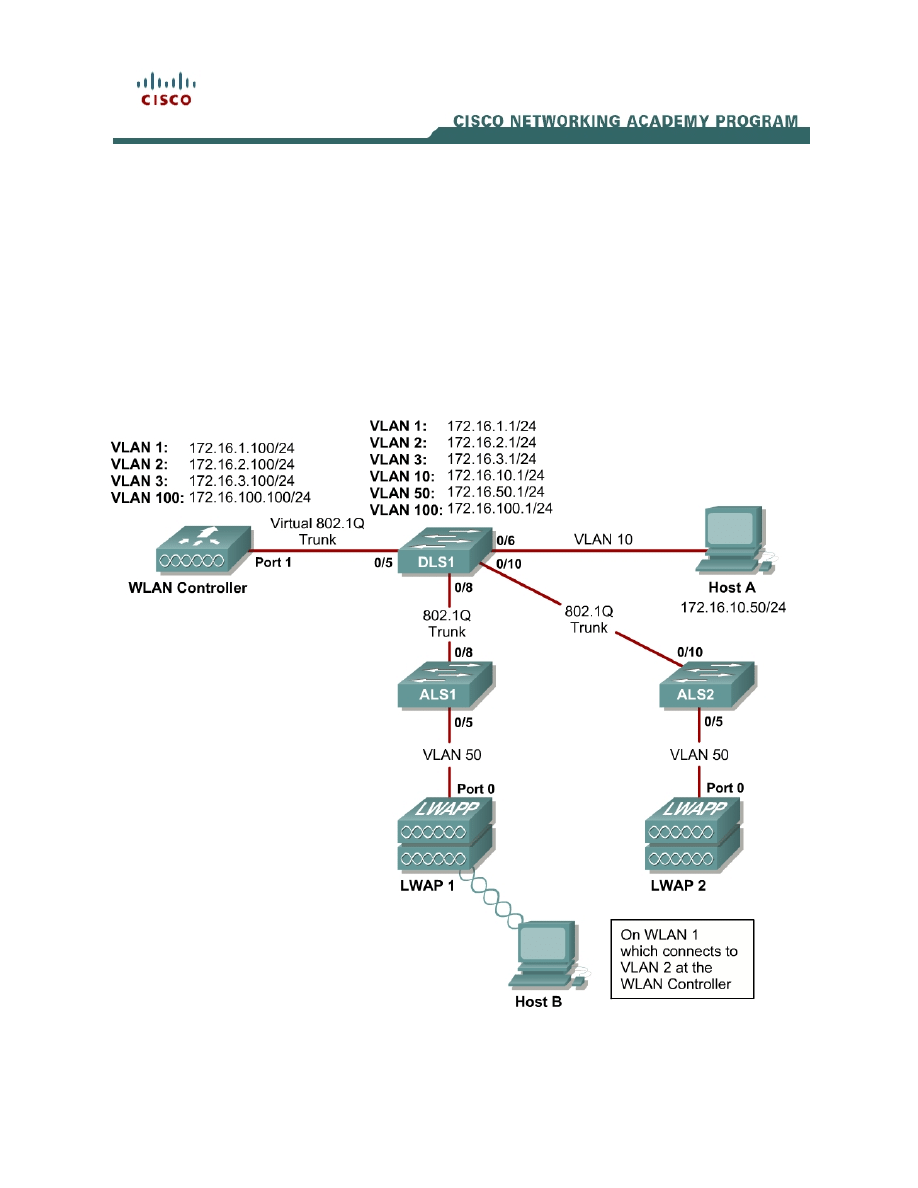
Figure 1-1: Ethernet Connectivity Diagram for Module 6, External WLAN Controller
Connectivity Diagram using a Wireless LAN Controller Network Module
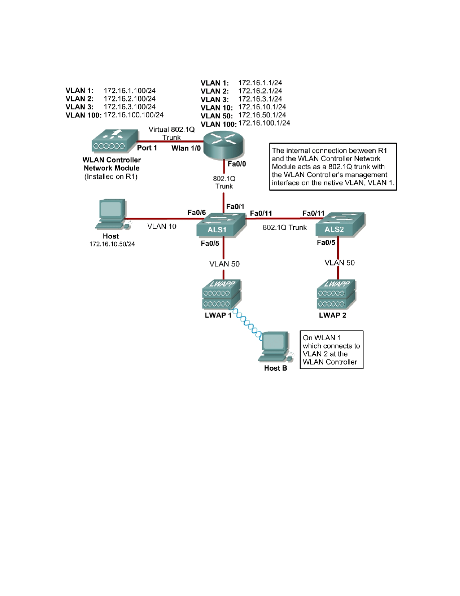
Figure 1-2: Ethernet Connectivity Diagram for Module 6, Internal WLAN Controller
Scenario
In this lab, you will configure and verify Wi-Fi Protected Access ( WPA) security
in a wireless environment using preshared keys.
This lab requires two separate PCs, Host A and Host B. Host A will act on
VLAN 10 as the Cisco access control server (ACS) server and will also be used
to configure the wireless LAN (WLAN) controller as a PC has been used to do
in previous labs. Host B requires a Cisco wireless network card with the Aironet
Desktop Utility installed. Host B will function as a wireless client on WLAN 1
which corresponds to VLAN 2.
2 - 18
CCNP: Optimizing Converged Networks v5.0 - Lab 6-4
Copyright
© 2007, Cisco Systems, Inc

You may complete this scenario using either the external WLAN controller
(WLC) or the network module that resides in a router. However, you must load
the final configurations from the end of Lab 6.1: Configuring a WLAN Controller.
We highly recommended that you complete Labs 6.1, 6.2, and 6.3 before
attempting this lab.
Note:
This lab will only go into the details of configuring WLAN security using WPA-
PSK. For more information on using the web interface of the WLC, consult
Lab 6.2: Configuring a WLAN Controller via the Web Interface.
Preparation
Complete Lab 6.1 and ensure that all switches and routers, the WLAN
controller, and the host are configured the way they would be at the end of Lab
6.1.
At the end of Lab 6.1, you should already have the following features configured
and verified:
• VLAN
connectivity
• Trunk
ports
• HTTP access to the WLC
• Lightweight Access Points (LWAPs) associated with the controller
Step 1: Connect to the WLC from the Host
On Host A, open up Internet Explorer and go to the URL https://172.16.1.100.
This is the secure method of connecting to the management interface of the
WLAN controller. You can also use http://172.16.1.100 since we previously
enabled regular insecure HTTP access in the command-line interface (CLI) for
Lab 6.1. If you connect to the secure address, you may be prompted with a
security warning. Click Yes to accept it and you will be presented with the login
screen for the WLAN controller. Click Login and an authentication dialog box
will appear.
3 - 18
CCNP: Optimizing Converged Networks v5.0 - Lab 6-4
Copyright
© 2007, Cisco Systems, Inc
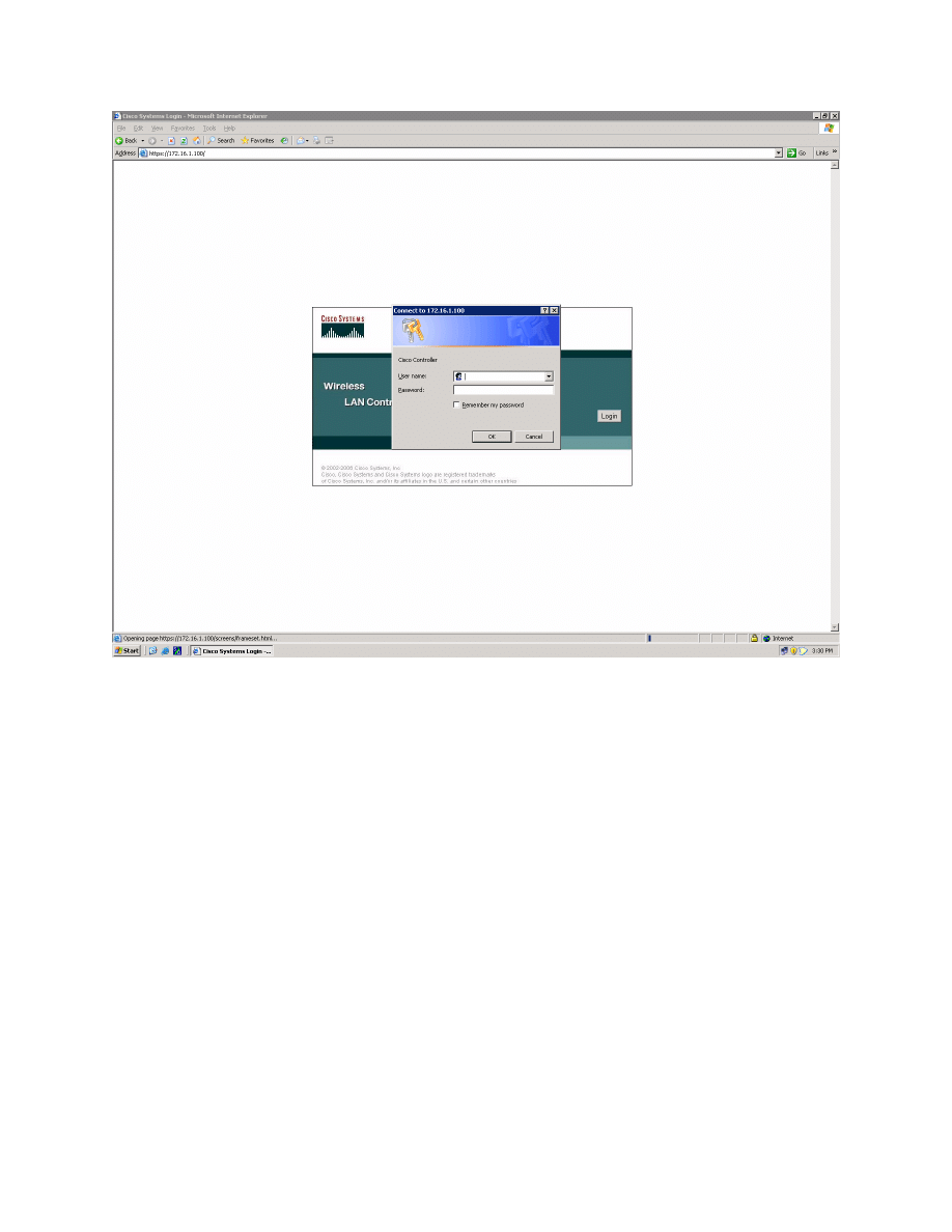
Figure 1-1: HTTP Access to the WLAN Controller
Use “cisco” as both the username and password. You configured these in the
previous lab. Click OK to get to the main page of the graphical user interface
(GUI). You are then presented with the monitor page for the WLAN controller.
4 - 18
CCNP: Optimizing Converged Networks v5.0 - Lab 6-4
Copyright
© 2007, Cisco Systems, Inc
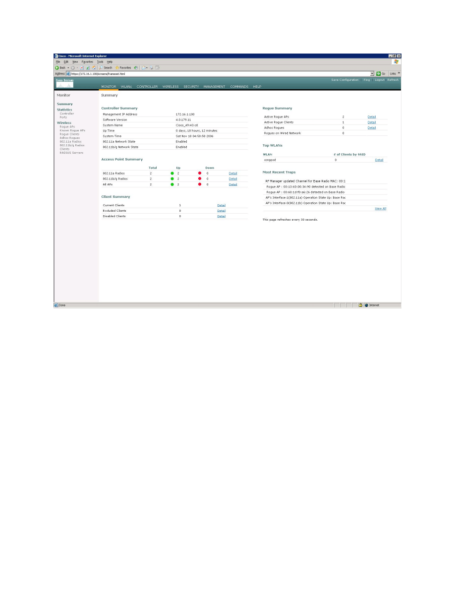
Figure 1-2: WLAN Controller Monitor Page
Make sure you see two access points under the “Access Point Summary” part
of the page. If you do not, reload the LWAPs, otherwise, troubleshoot. You may
also see it detecting rogue access points if your lab has other wireless networks
around it; this behavior is normal. You can also see various port controller and
port statistics by clicking their respective links on the left-hand menu on the
screen.
Step 2: Assign a VLAN to a WLAN
Since this step is identical to steps found in Lab 6.2: Configuring a WLAN
Controller via the Web Interface, we will not explain the many details of each of
the configuration changes. For more information on what these changes do,
reference Lab 6.2.
Click the Controller tab at the top of the window. Then, click Interfaces in the
left pane. Click New to create a new interface.
5 - 18
CCNP: Optimizing Converged Networks v5.0 - Lab 6-4
Copyright
© 2007, Cisco Systems, Inc
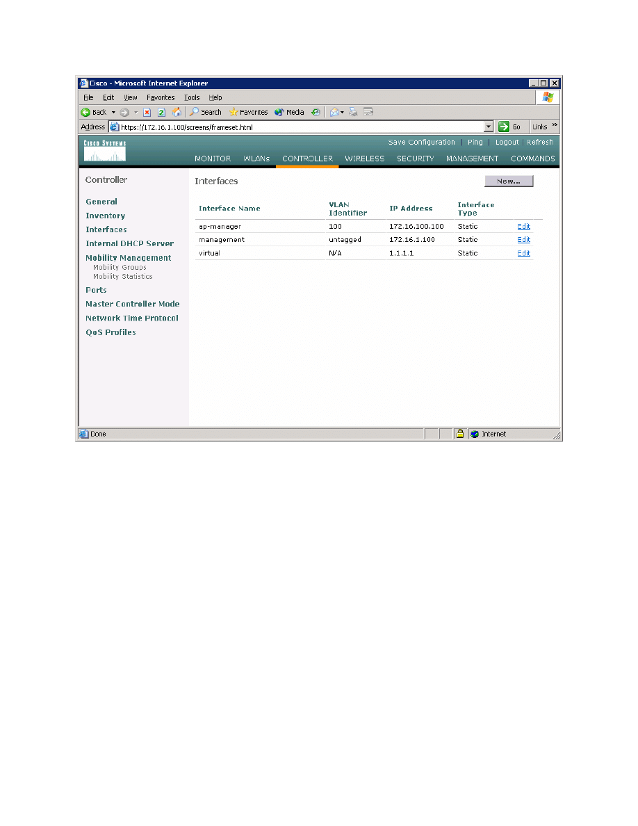
Figure 2-1: Interface Configuration Page
Name the interface “VLAN2” and assign it to 802.1Q tag 2, just like in Lab 6.2.
Click Apply when you have completed this.
6 - 18
CCNP: Optimizing Converged Networks v5.0 - Lab 6-4
Copyright
© 2007, Cisco Systems, Inc
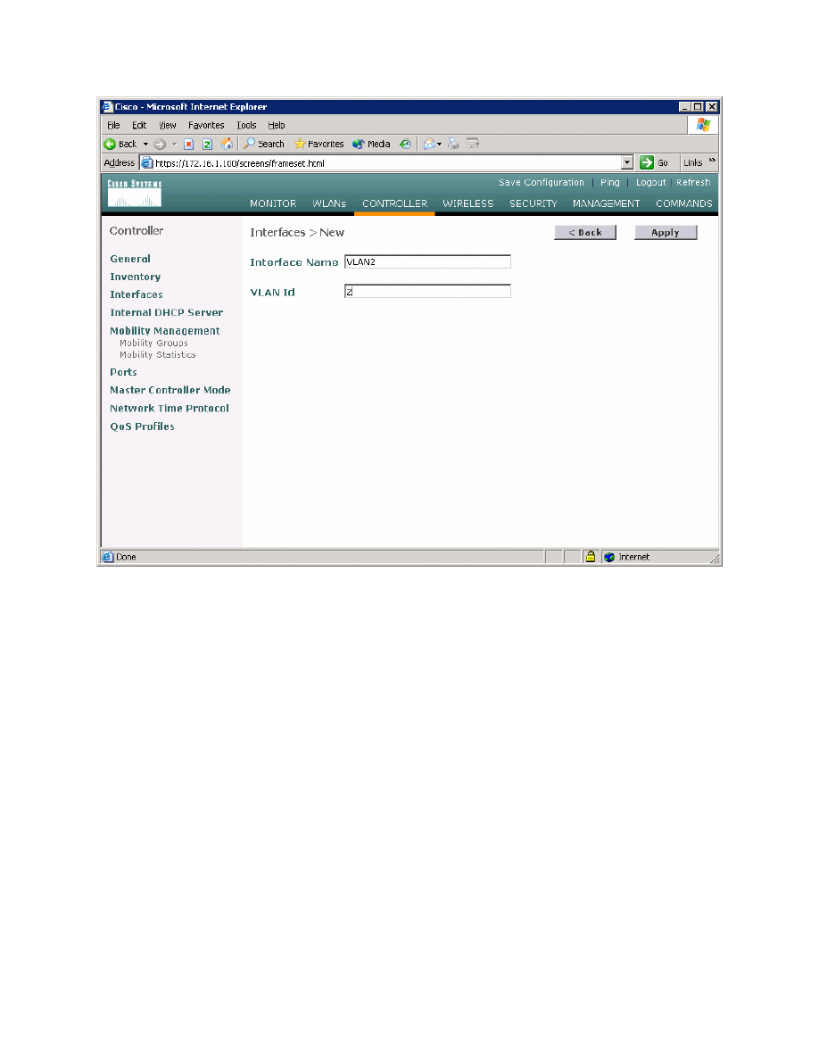
Figure 2-2: Creating a New VLAN Interface
Configure the IP address, default gateway, port number, and Dynamic Host
Configuration Protocol (DHCP) server for this interface as shown in Figure 2-3,
and then click Apply.
7 - 18
CCNP: Optimizing Converged Networks v5.0 - Lab 6-4
Copyright
© 2007, Cisco Systems, Inc
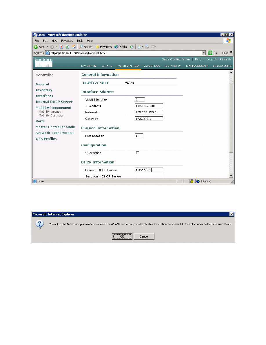
Figure 2-3: Configuring VLAN Interface Properties
Accept the warning by clicking OK.
Figure 2-4: Interface Parameter Confirmation
You should see the new interface in the interface list.
8 - 18
CCNP: Optimizing Converged Networks v5.0 - Lab 6-4
Copyright
© 2007, Cisco Systems, Inc
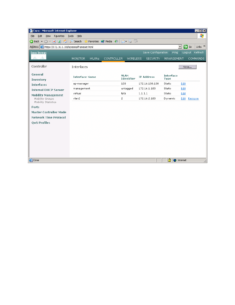
Figure 2-5: Verify Existing VLAN Interfaces
Click the WLANs tab at the top of the screen to view the current WLAN
configuration. Click Edit for the WLAN shown (it is towards the right of the
screen).
What is the default security policy for a WLAN? Hint: Reference Figure 2-6.
9 - 18
CCNP: Optimizing Converged Networks v5.0 - Lab 6-4
Copyright
© 2007, Cisco Systems, Inc
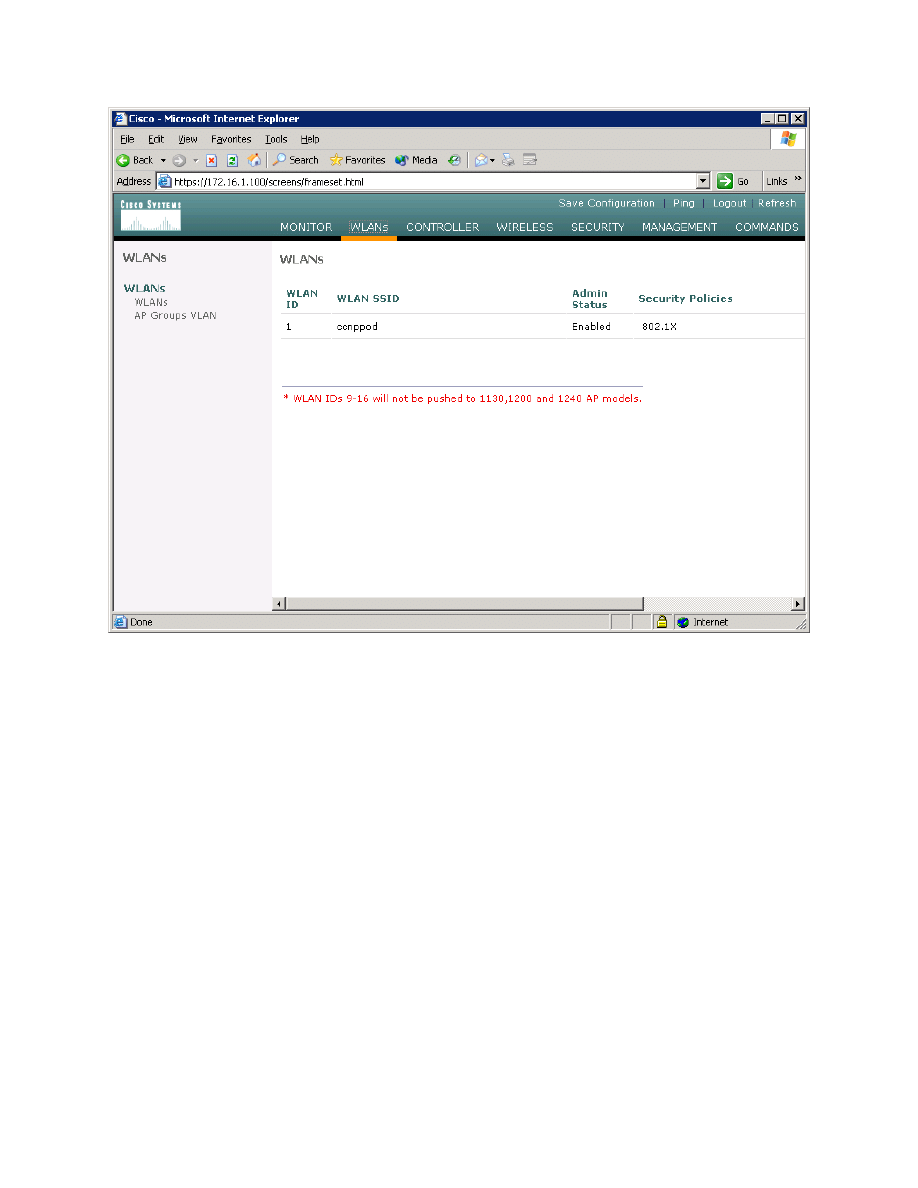
Figure 2-6: Viewing Existing WLANs with Security Policies
On the right side of the WLAN configuration page, change the layer 2 security
method to WPA1+WPA2. Also make sure that the Broadcast SSID option is
checked. Even though you are broadcasting the service set identifier (SSID), no
clients should be able to connect until you set the security policies configured
later.
10 - 18
CCNP: Optimizing Converged Networks v5.0 - Lab 6-4
Copyright
© 2007, Cisco Systems, Inc
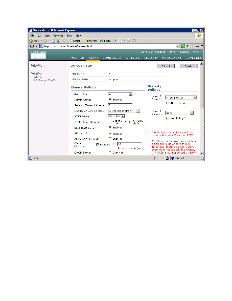
Figure 2-7: Editing the Configuration for WLAN 1
Scroll down the page and change the interface to the VLAN 2 interface created
earlier.
11 - 18
CCNP: Optimizing Converged Networks v5.0 - Lab 6-4
Copyright
© 2007, Cisco Systems, Inc
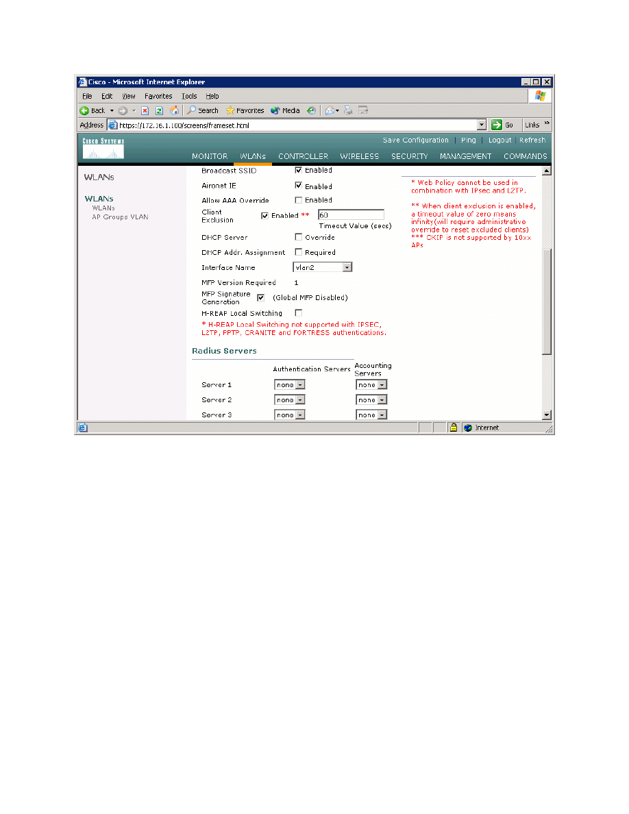
Figure 2-8: Editing the VLAN Interface Connected to WLAN 1
Use a WPA2 policy with Advanced Encryption Standard (AES) encryption.
Configure a preshared key of “password”. Click Apply at the top of the page
when done.
12 - 18
CCNP: Optimizing Converged Networks v5.0 - Lab 6-4
Copyright
© 2007, Cisco Systems, Inc
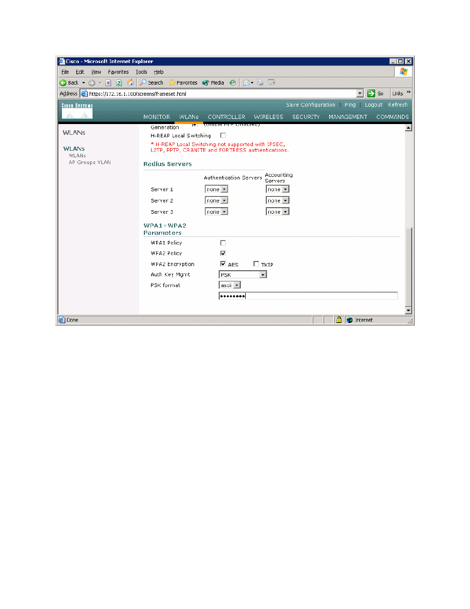
Figure 2-9: Editing the Security Policy for WLAN 1
You should be returned to the WLAN list screen with the new security method
shown. Assuming that the LWAPs are associated with the WLC correctly, they
should now broadcast this SSID and clients should be able to connect.
13 - 18
CCNP: Optimizing Converged Networks v5.0 - Lab 6-4
Copyright
© 2007, Cisco Systems, Inc

Figure 2-10: WLAN 1 with a WPA2 Security Policy
What is the benefit in configuring preshared keys as the wireless security
method?
What is the downside of configuring preshared keys as the wireless security
method?
14 - 18
CCNP: Optimizing Converged Networks v5.0 - Lab 6-4
Copyright
© 2007, Cisco Systems, Inc
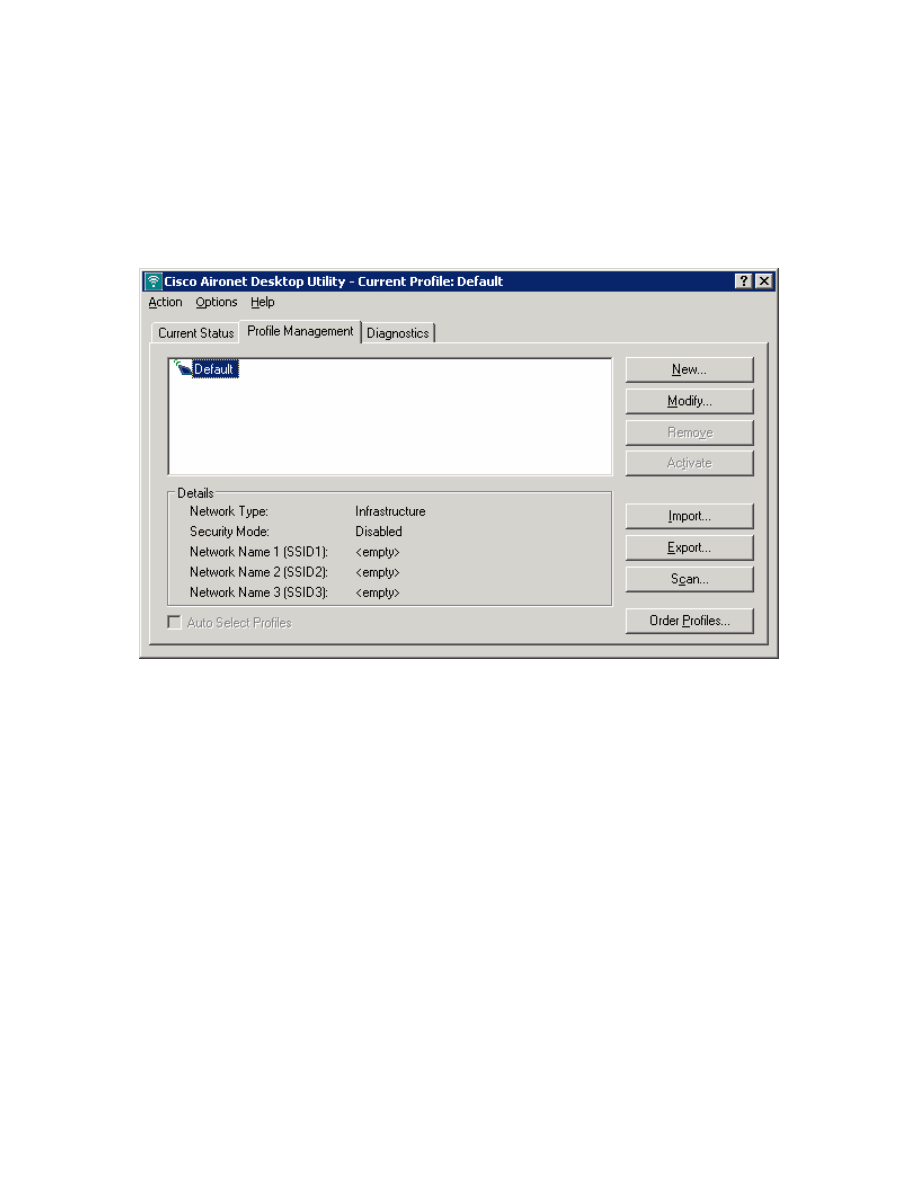
Step 3: Connect to WLAN Using Cisco Aironet Desktop Utility
On Host B, open up the Cisco Aironet Desktop Utility either by the icon on the
desktop or the program shortcut in the start menu. If you do not have the Cisco
Aironet Desktop Utility (ADU) installed, consult Lab 6.3: Configuring a Wireless
Client. Once in the ADU, click the Profile Management tab. Next, click New to
make a new profile.
Figure 3-1: Cisco ADU Profile Management Tab
Use a profile name and SSID of “ccnppod” since this was the SSID configured
in Lab 6.1. Use any client name desired. Here, “CiscoClient” is the name used.
15 - 18
CCNP: Optimizing Converged Networks v5.0 - Lab 6-4
Copyright
© 2007, Cisco Systems, Inc
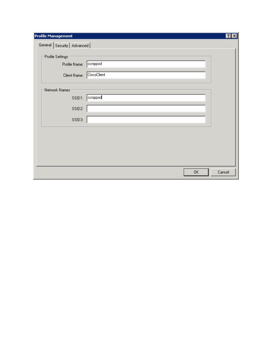
Figure 3-2: Configuring Profile Options and SSID
Click the Security tab and set the security type as WPA/WPA2 Passphrase.
We are using the passphrase because we configured preshared keys rather
than a more advanced method. After selecting the security method, click
Configure.
16 - 18
CCNP: Optimizing Converged Networks v5.0 - Lab 6-4
Copyright
© 2007, Cisco Systems, Inc
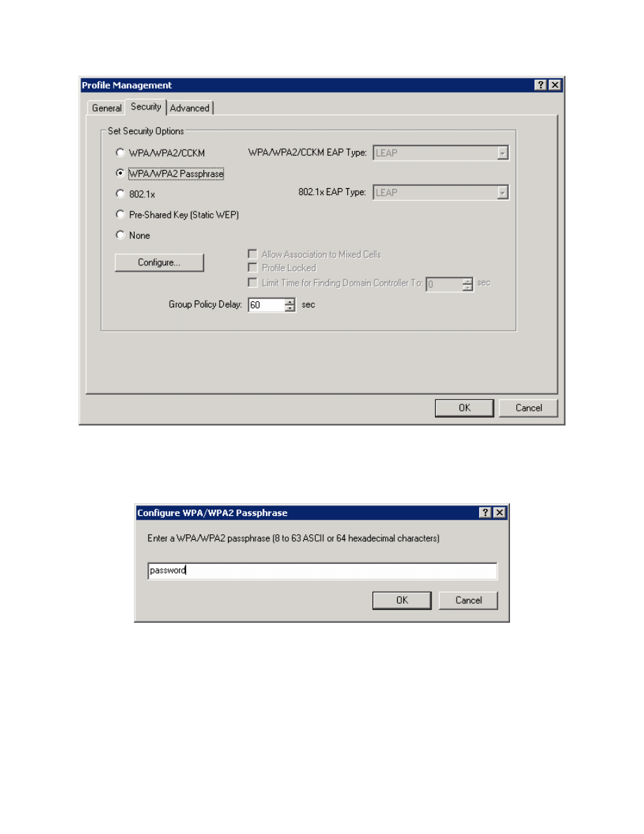
Figure 3-3: Wireless Security Options
Enter in the same password used before for WPA, which is “password,” and
then click OK.
Figure 3-4: Passphrase Configuration
Select the ccnppod profile and click Activate.
17 - 18
CCNP: Optimizing Converged Networks v5.0 - Lab 6-4
Copyright
© 2007, Cisco Systems, Inc
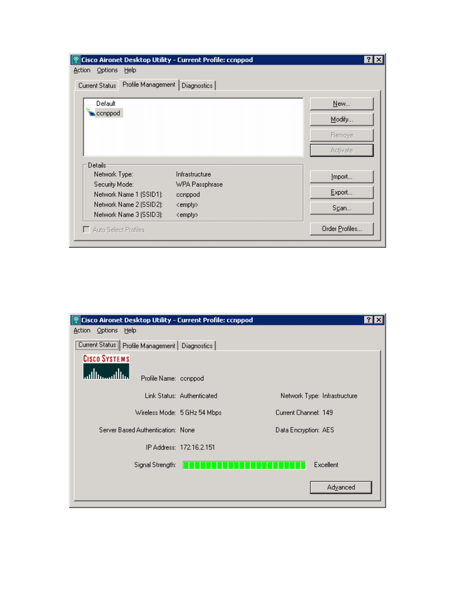
Figure 3-5: Selecting a Wireless Profile
Click the Current Status tab and make sure that you have received an IP
address in the correct subnet. If you receive a correct IP, you have successfully
configured and connected to the WLAN.
Figure 3-6: Current Wireless Profile Status
18 - 18
CCNP: Optimizing Converged Networks v5.0 - Lab 6-4
Copyright
© 2007, Cisco Systems, Inc
Wyszukiwarka
Podobne podstrony:
CCNP4 lab 4 9 en
CCNP4 lab 3 1 en
CCNP4 lab 4 7 en
CCNP4 lab 4 8 en
CCNP4 lab 3 2 en
CCNP4 lab 3 3 en
CCNP4 lab 4 2 en
CCNP4 lab 4 6 en
CCNP4 lab 5 1 en
CCNP4 lab 2 1 en
CCNP4 lab 4 4 en
CCNP4 lab 4 3 en
CCNP4 lab 6 3 en
CCNP4 lab 4 5 en
CCNP4 lab 4 1 en
CCNP4 lab 6 5 en
CCNP4 lab 6 5 en
CCNP4 lab 6 1b en
CCNP4 lab 6 2b en
więcej podobnych podstron