
Piotr Grześ
Finite element analysis of disc temperature during braking process
36
FINITE ELEMENT ANALYSIS OF DISC TEMPERATURE
DURING BRAKING PROCESS
Piotr GRZEŚ
*
*Faculty of Mechanical Engineering, Białystok Technical University, ul. Wiejska 45 C, 15-351 Białystok
p.grzes@doktoranci.pb.edu.pl
Abstract: The aim of this paper was to investigate the temperature fields of the solid disc brake during short, emergency bra-
king. The standard Galerkin weighted residual algorithm was used to discretize the parabolic heat transfer equation. The fi-
nite element simulation for two-dimensional model was performed due to the heat flux ratio constantly distributed in circum-
ferential direction. Two types of disc brake assembly with appropriate boundary and initial conditions were developed. Re-
sults of calculations for the temperature expansion in axial and radial directions are presented. The effect of the angular ve-
locity and the contact pressure evolution on temperature rise of disc brake was investigated. It was found that presented finite
element technique for two-dimensional model with particular assumption in operation and boundary conditions validates wi-
th so far achievements in this field.
1. INTRODUCTION
Over decades, frictional heating in brakes and clutches
has been investigated by many researches. Temperature rise
affected by conversion of large amounts of kinetic energy
into heat energy is a complex phenomenon. All characteris-
tics of the process (velocity, pressure, friction coefficient,
thermal properties of the materials) vary with time. How-
ever, it is important to predict temperature distribution
of heat generation during braking and clutch engagement.
Long repetitive braking terms, particularly during
mountain descents or high-speed stops (autobahn stop) may
cause significant concern. Undesirable effects (low fre-
quency vibrations, fade of the lining with variations of
friction coefficient, premature wear, brake fluid vaporiza-
tion) directly affect braking performance. Hence it is essen-
tial to know the peak temperatures at the beginning of the
design process.
Talati and Jalalifar (2008, 2009) formulated the problem
of two models of heat dissipation in disc brakes: namely
macroscopic and microscopic model. In the macroscopic
model First Law of Thermodynamics has been taken into
account and for microscopic model various characteristics
such as duration of braking, material properties, dimensions
and geometry of the brake system have been studied.
Both disc and pad volume have been investigated to evalu-
ate temperature distributions. The conduction heat transfer
was
investigated using finite element method (Talati
and Jalalifar, 2008). In paper (Talati and Jalalifar, 2009)
problem was solved analytically using Green’s function
approach. Influence of thermomechanical distortions during
heat generation has been neglected.
Gao and Lin (2002) investigated non-axisymmetrical
model of disc brake system with moving heat source. Ap-
propriate boundary conditions due to analytical model have
been imposed. To solve the problem, a transient FE tech-
nique has been used. Numerical estimations reveal that the
operating parameters of the braking process significantly
influence the disc/pad interface temperature distribution
and the maximal contact temperature.
According to Ramachandra Rao et al. (1989) it is essen-
tial that the analysis is treated as a nonlinear (thermal con-
ductivity and enthalpy for the disc material vary with re-
spect to temperature). In this paper the simulation
of the temperature field in the disc brake has been carried
out using the finite element method. Both, wear and tem-
perature distribution have been considered. The computer
simulation of the fade mechanism using 'clock mechanism'
is examined which is also verified with the experimental
outcome.
Grieve et al. (1998) compares different materials
for pad element of automotive disc brake with its signifi-
cant weight advantages corresponds to lower maximum
operating temperature. Three dimensional model of brake
system assembly has been imposed with the finite element
method simulation. The author examines the effect of the
vehicle mass on the peak disc temperatures. Also Taguchi
technique (1993) has been applied to develop influence of
all the critical design and material factors.
FE modelling of the heat generation process in a mine
winder disc brake is proposed in monograph: Ścieszka and
Żołnierz (2007).
In this study, transient thermal analysis of disc brake
utilizing finite element method is developed. Both analyti-
cal and numerical investigations are performed. Various
boundary and operation conditions in two types of FE mod-
els with appropriate material properties (Talati and Jalalifar,
2009; Gao and Lin, 2002) are established.
acta mechanica et automatica, vol.3 no.4 (2009)
37
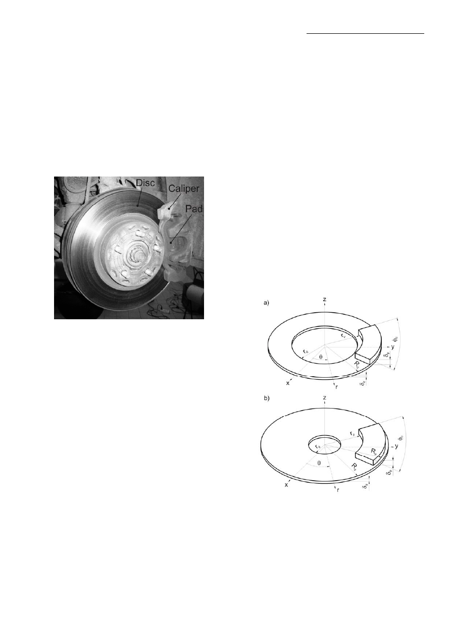
2. REAL PROBLEM
Disc brake consists of cast-iron disc which rotates with
the wheel, caliper fixed to the steering knuckle and friction
material (brake pads) which is shown in Fig 1. When
the braking process occurs, the hydraulic pressure forces
the piston and therefore pads and disc brake are in sliding
contact. Set up force resists the movement and the vehicle
slows down or eventually stops. Friction between disc
and pads always opposes motion and the heat is generated
due to conversion of the kinetic energy. However, friction
surface is exposed to the enlarged air flow for high speed
braking and the heat is dissipated.
Fig. 1. Front disc brake of the passenger’s car
Disc brake. In general disc brakes are made of gray cast
iron and are either solid or ventilated. The ventilated types
of discs have vanes or fins to increase surface of heat ex-
change by convection. Furthermore, higher order of disc
brakes have drilled holes. Nowadays a cross-drilled discs
are commonly used in motorcycles, racing cars or very high
performance road cars. Cross-drilled enables more efficient
gas release in the brake exert. The disc must have limited
mass in order to diminish the inertia forces and non-
suspending mass.
Pads. Several assumptions should be considered in the case
of design process of friction material. It is known that the
value of sliding friction depends of the nature of two sur-
faces which touch each other. Material selection must deal
with the coefficient of friction which is supposed to remain
constant in the braking process corresponding to wide vari-
ety of disc/pad interface temperature. Also wear is vital in
case of braking performance.
Caliper. Generally two types of calipers are commonly
used: the floating calipers and the fixed calipers. Depend-
ing on the way of operation, the floating caliper has either
one or two pistons.
In the floating caliper (Fig. 1) the piston is located only
in one side of the disc. Equal pressure at the same time
is distributed on the two inner surfaces of pads by using
reaction when the pressure acts piston on the one side
of the disc.
The fixed caliper have two pistons in both sides of the
disc brake. The equilibrium of pressure at any pad is settled
by the single source of the hydraulic pressure partitioned
to each canal of the piston. This type of caliper is heavier
and also larger because of complexity of the disc brake
assembly. The advantage is that they absorb more energy
by heat dissipation.
3. PHYSICAL PROBLEM
Disc brake system consists of two elements: rotating
axisymmetric disc and immovable non-axisymmetric pad
(Fig. 2). The most important function of disc brake system
in automotive application is to reduce velocity of the vehi-
cle by changing the kinetic energy into thermal energy.
When the braking process occurs total heat is dissipated
by conduction from disc/pad interface to adjacent compo-
nents of brake assembly and hub and by convection to
atmosphere in accordance to Newton’s law. The radiation
may be neglected due to relatively low temperature and
short time of the braking process.
In this paper for validation of proposed finite element
(FE) modeling technique, two types of solid disc brake
were analyzed (Fig. 2). Type A according to Talati and
Jalalifar’s paper (2009) and Type B according to Gao and
Lin’s paper (2002).
Fig. 2. The schematic representation of disc brake
system a) Type A; b) Type B
For both types it has been assumed as follows:
1) Material properties are isotropic and independent of the
temperature;
2) The real surface of contact between a disc brake and
pad in operation is equal to the apparent surface in the

Piotr Grześ
Finite element analysis of disc temperature during braking process
38
sliding contact. Hence pressure is uniformly distributed
over all friction surfaces;
3) The average intensity of heat flux into disc on the con-
tact area equals (Ling, 1973):
(
)
)
(
)
(
2
,
,
0
t
r
t
fp
t
z
r
q
d
z
d
ω
π
φ
γ
δ
=
=
,
(1)
p
p
R
r
r
≤
≤
,
s
t
t
≤
≤
0
,
and into pad
(
)
( )
t
r
t
fp
t
z
r
q
p
z
p
ω
γ
δ
)
(
)
1
(
,
,
−
=
=
,
(2)
p
p
R
r
r
≤
≤
,
s
t
t
≤
≤
0
,
where:
γ is the heat partitioning factor, φ
0
is the cover
angle of pad,
f is the friction coefficient, p is the contact
pressure,
ω is the angular velocity, t is the time, t
s
is the
braking time, r is the radial coordinate, z is the axial co-
ordinate, r
p
and R
p
are the internal and external radius
of the pad. The subscripts p and d imply the pad and the
disc respectively;
4) The heat partitioning factor representing the fraction
of frictional heat flux entering the disc has the form
(Blok, 1940):
d
d
d
p
p
p
K
c
K
c
ρ
ρ
γ
+
=
1
1
,
(3)
where
ρ is the density, c is the specific heat and K is the
thermal conductivity;
5) The frictional heat due to Newton law has been dissi-
pated to atmosphere on the other surfaces. The heat
transfer coefficient h is constant during braking process;
6) Because of short braking time and hence relatively low
temperature the radiation is neglected.
Two types of single disc have been analyzed with its
simplification to symmetrical problem. Therefore one side
of the disc has been insulated in both types of the FE
model.
In Type A the single surface of disc symmetry is insu-
lated. Excluding both the surface of symmetry and the
surface of sliding contact with the intensity of heat flux
boundary condition, on all remaining surfaces the exchange
of thermal energy by convection to atmosphere has been
implied.
Furthermore in Type B the inner surface of disc was
thermally insulated. On the area of sliding contact of disc
brake surface intensity of the heat flux has been estab-
lished. The frictional heat due to Newton law has been
dissipated to atmosphere on the other surfaces.
In Type A the contact pressure p is given as follows
0
p
p
=
,
(4)
and the angular velocity
ω is linear in time t:
( )
⎟⎟
⎠
⎞
⎜⎜
⎝
⎛
−
=
0
0
1
s
t
t
t
ω
ω
,
0
0
s
t
t
≤
≤
(5)
where: p
0
is the nominal pressure,
ω
0
is the initial angular
velocity,
t
s
0
is the time of braking with constant decelera-
tion.
The opposite approach is presented in Type B. It is as-
sumed, that the pressure varies with time (Chichinadze et
al., 1979)
⎟
⎟
⎠
⎞
⎜
⎜
⎝
⎛
−
=
−
m
t
t
e
p
t
p
1
)
(
0
,
s
t
t
≤
≤
0
,
(6)
where: t
m
is the growing time. The angular velocity corre-
sponds to pressure (6) and is equal (Yevtushenko et al.,
1999)
( )
⎥
⎥
⎦
⎤
⎢
⎢
⎣
⎡
⎟
⎟
⎠
⎞
⎜
⎜
⎝
⎛
−
+
−
=
−
m
t
t
s
m
s
e
t
t
t
t
t
1
1
0
0
0
ω
ω
,
s
t
t
≤
≤
0
,
(7)
4. MATHEMATICAL MODEL
To evaluate the contact temperature conditions, both
analytical and numerical techniques have been developed.
The starting point for the analysis of the temperature field
in the disc volume is the parabolic heat conduction equation
in the cylindrical coordinate system (r,
θ, z) which is cen-
tered in the axis of disc and z points to its thickness
(Nowacki, 1962)
0
,
0
,
2
0
,
,
1
1
1
2
2
2
2
2
2
2
>
<
<
≤
≤
≤
≤
∂
∂
=
∂
∂
+
∂
∂
+
∂
∂
+
∂
∂
t
z
R
r
r
t
T
k
z
T
T
r
r
T
r
r
T
d
d
d
d
δ
π
θ
θ
(8)
where k
d
is the thermal diffusivity of the disc, r
d
and R
d
are he internal and external radius of the disc. In an auto-
motive disc brakes the Peclet numbers almost always are
in order 10
5
. Hence the distribution of heat flow will be
uniform in circumferential direction, which means that
neither temperature nor heat flow will vary in
θ direction
and thus the heat conduction equation reduces to
t
T
k
z
T
r
T
r
r
T
d
∂
∂
=
∂
∂
+
∂
∂
+
∂
∂
1
1
2
2
2
2
,
d
d
R
r
r
≤
≤
,
d
z
δ
<
<
0
,
0
>
t
, (9)
The boundary and initial conditions are given
as follows:
Type A
⎪⎩
⎪
⎨
⎧
≤
≤
≤
≤
≥
≤
≤
−
=
∂
∂
=
,
0
,
),
,
,
(
,
0
,
)],
,
,
(
[
s
p
p
d
d
p
d
d
a
z
d
t
t
R
r
r
t
r
q
t
r
r
r
t
r
T
T
h
z
T
K
d
δ
δ
δ
(10)
where T
a
is the ambient temperature.
)]
,
,
(
[
t
z
R
T
T
h
r
T
K
d
a
R
r
d
d
−
=
∂
∂
=
,
d
z
δ
≤
≤
0
,
0
≥
t
, (11)
)]
,
,
(
[
t
z
r
T
T
h
r
T
K
d
a
r
r
d
d
−
−
=
∂
∂
=
,
d
z
δ
≤
≤
0
,
0
≥
t
, (12)
0
0
=
∂
∂
=
z
z
T
,
d
d
R
r
r
≤
≤
,
0
≥
t
,
(13)
0
)
0
,
,
(
T
z
r
T
=
,
d
d
R
r
r
≤
≤
,
d
z
δ
≤
≤
0
,
(14)

acta mechanica et automatica, vol.3 no.4 (2009)
39
Type B
⎪⎩
⎪
⎨
⎧
≥
≤
≤
≥
≤
≤
∧
≤
≤
−
=
∂
∂
=
,
0
,
),
,
,
(
,
0
,
)],
,
,
(
[
t
R
r
r
t
r
q
t
R
r
R
r
r
r
t
r
T
T
h
z
T
K
p
p
d
d
d
p
p
d
d
a
z
d
d
δ
δ
δ
(15)
)],
,
,
(
[
t
z
R
T
T
h
r
T
K
d
a
R
r
d
d
−
=
∂
∂
=
d
z
δ
≤
≤
0
,
0
≥
t
, (16)
0
=
∂
∂
=
d
r
r
r
T
,
d
z
δ
≤
≤
0
,
0
≥
t
,
(17)
0
0
=
∂
∂
=
z
z
T
,
d
d
R
r
r
≤
≤
,
0
≥
t
,
(18)
0
)
0
,
,
(
T
z
r
T
=
,
d
d
R
r
r
≤
≤
,
d
z
δ
≤
≤
0
,
(19)
The above cases are two-dimensional problem for transient
analysis. The boundary and initial conditions are specified
for subsequent types of disc.
5. FE FORMULATION
The object of this section is to develop approximate
time-stepping procedures for axisymmetrical transient go-
verning equations. For this to happen, the following bound-
ary and initial conditions are considered
p
T
T
=
on
T
Γ
(20)
(
)
a
T
T
h
q
−
−
=
on
h
Γ
(21)
d
q
q
=
on
q
Γ
(22)
0
T
T
=
on at time
0
=
t
(23)
where T
p
is the prescribed temperature,
Γ
Τ
,
Γ
h
, Γ
q
, are
arbitrary boundaries on which temperature, convection and
heat flux are prescribed.
In order to obtain matrix form of Eq. (9) the application
of standard Galerkin’s approach was conducted (Lewis et
al., 2004). The temperature was approximated over space as
follows
(
)
( ) ( )
∑
=
=
n
i
i
i
t
T
z
r
N
t
z
r
T
1
,
,
,
(24)
where: N
i
are shape functions, n is the number of nodes
in an element, T
i
(t) are time dependent nodal temperatures.
The standard Galerkin’s approach of Eq. (9) leads to the
following equation
0
1
2
2
2
2
=
Ω
⎥
⎦
⎤
⎢
⎣
⎡
∂
∂
−
∂
∂
+
∂
∂
+
∂
∂
∫
Ω
d
t
T
c
z
T
r
T
r
r
T
N
K
d
d
i
d
ρ
(25)
Using integration by parts of Eq. (25) we obtain
0
=
Γ
∂
∂
+
Γ
∂
∂
+
Ω
⎥⎦
⎤
⎢⎣
⎡
∂
∂
+
∂
∂
−
∂
∂
∂
∂
+
∂
∂
∂
∂
−
∫
∫
∫
Γ
Γ
Ω
nd
z
T
N
K
ld
r
T
N
K
d
t
T
c
N
r
T
r
N
z
T
z
N
r
T
r
N
K
i
d
i
d
d
d
i
i
i
i
d
ρ
(26)
Integral form of boundary conditions
(
)
∫
∫
∫
∫
Γ
Γ
Γ
Γ
Γ
−
−
Γ
−
=
Γ
∂
∂
+
Γ
∂
∂
h
q
h
a
i
q
d
i
i
d
i
d
d
T
T
h
N
d
q
N
nd
z
T
N
K
ld
r
T
N
K
(27)
Substituting Eq. (27) and spatial approximation Eq. (24)
to Eq. (26) we obtain
(
)
0
=
Γ
−
−
Γ
−
Ω
∂
∂
−
Ω
⎥
⎥
⎥
⎥
⎦
⎤
⎢
⎢
⎢
⎢
⎣
⎡
∂
∂
−
∂
∂
∂
∂
+
∂
∂
∂
∂
−
∫
∫
∫
∫
Γ
Γ
Ω
Ω
h
q
h
a
i
q
d
i
j
j
i
d
d
j
j
i
j
i
j
i
d
d
T
T
h
N
d
q
N
d
T
t
N
N
c
d
T
r
N
r
N
z
N
z
N
r
N
r
N
K
ρ
(28)
where i and j represent the nodes.
Equation (28) can be written in matrix form
}
{
]
][
[
]
[
R
T
K
t
T
C
=
+
⎭
⎬
⎫
⎩
⎨
⎧
∂
∂
(29)
where [C] is the heat capacity matrix, [K] is the heat con-
ductivity matrix, and {R} is the thermal force matrix.
or
}
{
]
][
[
]
[
i
j
ij
j
ij
R
T
K
t
T
C
=
+
⎭
⎬
⎫
⎩
⎨
⎧
∂
∂
(30)
where
∫
Ω
Ω
=
d
N
N
c
C
j
i
d
d
ij
ρ
]
[
(31)
Γ
+
Ω
⎟⎟
⎠
⎞
⎜⎜
⎝
⎛
∂
∂
−
∂
∂
∂
∂
+
∂
∂
∂
∂
=
∫
∫
Γ
Ω
d
N
hN
d
T
r
N
r
N
T
z
N
z
N
T
r
N
r
N
K
K
j
i
j
j
i
j
j
i
j
j
i
d
ij
}
{
}
{
}
{
]
[
(32)
h
a
i
q
i
d
i
d
hT
N
d
N
q
R
h
q
Γ
+
Γ
−
=
∫
∫
Γ
Γ
]
[
(33)
or in matrix form
∫
Ω
Ω
=
d
N
N
c
C
T
d
d
]
[
]
[
]
[
ρ
(34)
Γ
+
Ω
=
∫
∫
Γ
Ω
d
N
N
h
d
B
D
B
K
T
T
]
[
]
[
]
][
[
]
[
]
[
(35)
h
T
a
q
T
d
d
N
hT
d
N
q
R
h
q
Γ
+
Γ
−
=
∫
∫
Γ
Γ
]
[
]
[
}
{
(36)
In order to solve the ordinary differential equation (29)
the direct integration method was used. Based on the as-
sumption that temperature {T}
t
and {T}
t+
Δ
t
at time t and
t+
Δt respectively, the following relation is specified
{ }
{ } (
)
t
t
T
t
T
T
T
t
t
t
t
t
t
Δ
⎥
⎦
⎤
⎢
⎣
⎡
⎭
⎬
⎫
⎩
⎨
⎧
∂
∂
+
⎭
⎬
⎫
⎩
⎨
⎧
∂
∂
−
+
=
Δ
+
Δ
+
β
β
1
(37)
Substituting Eq. 37 to Eq. 29 we obtain the following
implicit algebraic equation
Piotr Grześ
Finite element analysis of disc temperature during braking process
40
(
)
(
)
(
)
(
)
t
t
t
t
t
t
R
t
R
t
T
t
K
C
T
K
t
C
Δ
+
Δ
+
Δ
+
Δ
−
+
Δ
−
−
=
Δ
+
}
{
}
{
1
}
{
]
[
1
]
[
}
{
]
[
]
[
β
β
β
β
(38)
where
β is the factor which ranges from 0.5 to 1 and is
given to determine an integration accuracy and stable
scheme.
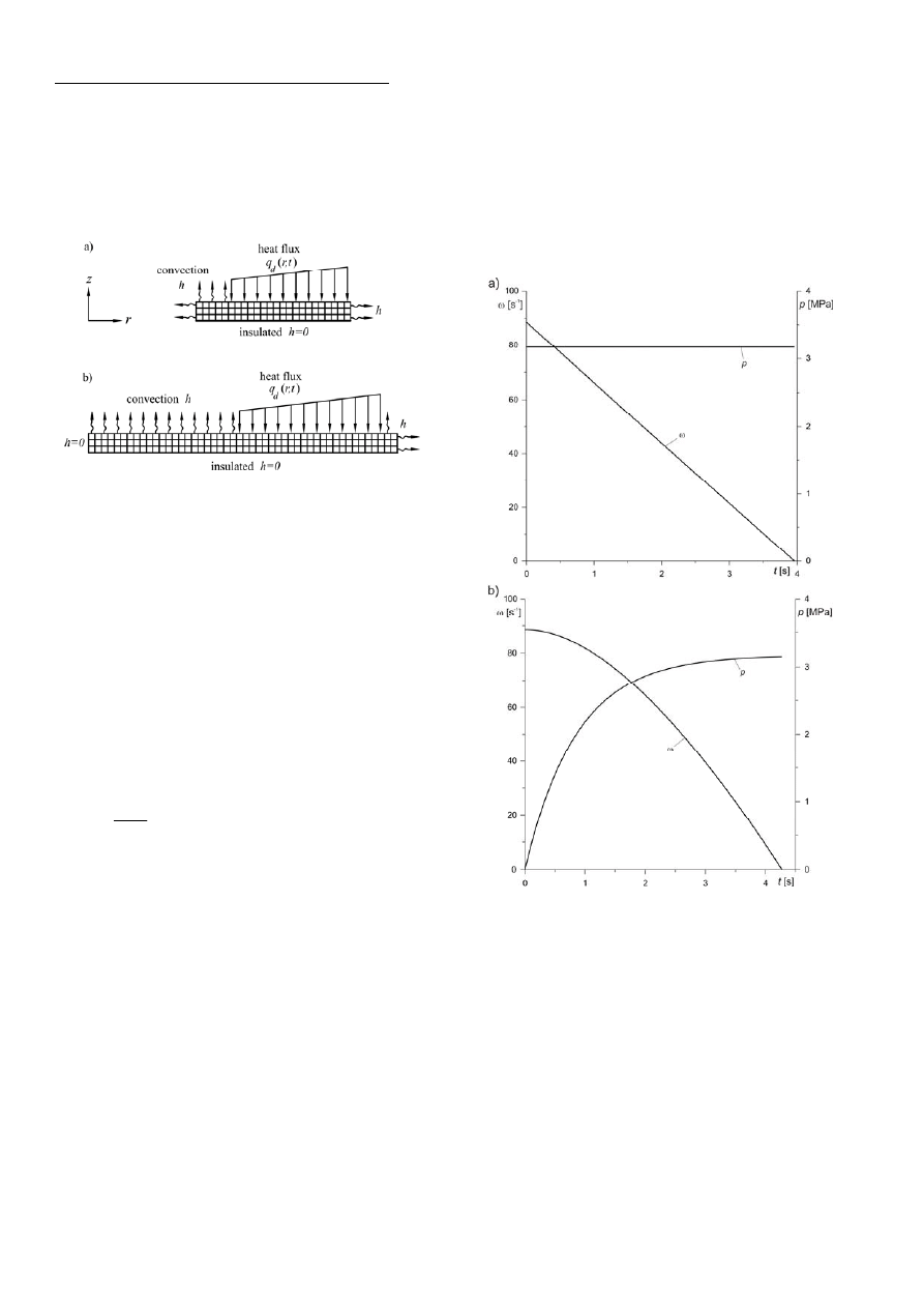
Fig. 3. FE models with boundary conditions
for the transient analysis a) Type A, b) Type B
The finite element formulation of disc brakes with
boundary conditions is shown in Fig. 3. Two FE models
described below were analyzed using the MD Patran/MD
Nastran software package (Reference Manual MD Nastran,
2008; Reference Manual MD Patran, 2008). In the thermal
analysis of disc brakes an appropriate finite elements divi-
sion is indispensable. In this paper eight-node quadratic
elements were used for finite element analysis. Type A
consists of 235 elements and 810 nodes and Type B 570
elements and 1913 nodes. High order of elements ensure
appropriate numerical accuracy.
To avoid inaccurate or unstable results, a proper initial
time step associated with spatial mesh size is essential
(Reference Manual MD Nastran, 2008).
d
d
d
K
c
x
t
10
2
ρ
Δ
=
Δ
(39)
where
Δt is the time step, Δx is the mesh size (smallest
element dimension). In this paper fixed
Δt =0.005s time
step was used.
6. RESULTS AND DISCUSSION
In this paper temperature distributions in disc brake
model without pad have been investigated. It is connected
with its sophisticated behaviour and importance of opera-
tion. Disc material is subjected to high temperatures action
which may cause non-uniform pressure distribution, ther-
mal distortions, low frequency vibrations. Both convection
and conduction have been analyzed. Particularly conduc-
tion was considered to be the most important mode of heat
transfer.
In order to validate proposed transient numerical analy-
sis two different types of the FE model were investigated
(Talati and Jalalifar, 2009; Gao and Lin, 2002). A transient
solution for Type A was performed for operation conditions
of constant contact pressure p
0
=3.17MPa and initial angular
velocity
ω
0
=88.46s
-1
during 3.96s of braking process
(Fig. 4a). Evolution of the pressure p and angular velocity
of the disc
ω for Type B is shown in Fig. 4b. Material prop-
erties and operation conditions adopted in the analysis
for both types of disc numerical model are given in Tab. 1
and Tab. 2 respectively.
Fig. 4. Evolution of the pressure p and angular velocity
ω
during
braking: a) Type A, b) Type B
Fig. 5a shows disc surface temperature distribution
for transient numerical computation (Type A) at different
radial distances. As it can be seen values of temperature
increase with radial distances. The highest temperature
of brake exert occurs at 113.5mm of radial position
and t=3.025s of time. Temperature distribution corresponds
intermediately to the intensity of heat flux, which rises with
time until the value of velocity and pressure product attains
highest, critical value. Hence temperature indirectly in-
creases with time and decreases when the intensity of heat
flux q
d
descents. The slope ∂T/∂t of plots r=75.5mm,
r=80mm, r=90mm, r=100mm, r=113.5mm decreases with
time. It agree well with Talati and Jalalifar’s paper (2009)
with distinction to values of temperatures. In this paper the
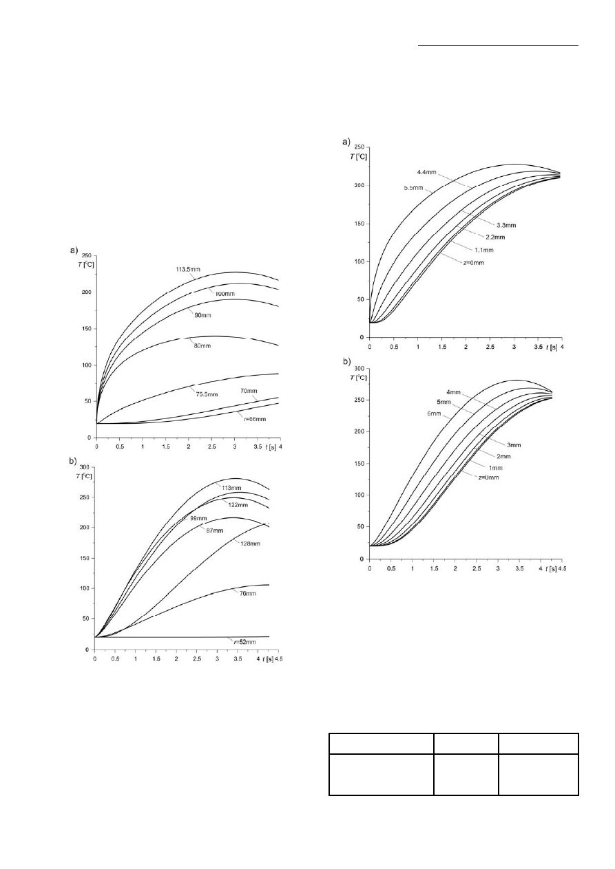
acta mechanica et automatica, vol.3 no.4 (2009)
41
highest temperature of disc area, which occurs during emer-
gency braking achieves 227.90
0
C. Meanwhile maximum
temperature obtained in Talati’s model of disc brake
is higher and equals approximately 300
0
C.
Fig. 5b shows disc temperature surface variations along
radial direction obtained in numerical computation for Type
B. In opposite to constant pressure at the disc/pad interface,
in this case pressure differs with time (Fig. 4b.). Also angu-
lar velocity has been assumed as a nonlinear. As it can be
seen temperature at inner disc surface (r=52 mm) has
a constant value 20
0
C. It corresponds to boundary condi-
tions, where surface was insulated. Maximum temperature
rise up to 280.9
0
C at 113mm of radial position and 3.49s
of time.
Fig. 5. Evolution of the disc temperature on the friction surface
for different values of the radial position:
a) Type A, b) Type B
In Fig. 6a disc temperature in Type A at r=113.5mm
and at different axial positions is illustrated. Symmetry
in axial direction has been assumed. Hence plots from
z=0mm to maximum thickness of the disc are shown. At the
initial period of disc brake engagement maximum tempera-
ture distribution appears at the disc/pad interface
(z=5.5mm). There is a tendency to convergence of tempera-
ture at different axial positions at the end of braking proc-
ess. It is connected with alignment of temperatures in disc
brake in subsequent stage of the process when the intensity
of heat flux descents. Temperature of plots z=4.4mm,
z=5.5mm rises with time to 3.47s and 3.025s respectively.
Fig. 6. Evolution of the disc temperature at different axial
distances and at radial position:
a) r=113.5mm (Type A) b) r=113mm (Type B)
In Fig. 6b temperature distribution at r=113mm in dif-
ferent axial distances is shown. As it can be seen tempera-
ture of plots z=4mm, z=5mm, z=6mm increases with time
to 4s, 3.74s and 3.44s respectively and then decreases while
temperature of plots z=0mm, z=1mm, z=2mm, z=3mm
constantly grows.
Tab. 1. Material properties used in finite element analysis
Type A [13]
Type B [3]
Thermo-physical properties
Disc Pad Disc Pad
thermal conductivity,
K
d
[W/mK]
43 12
48.46 1.212
heat capacity, c
d
[J/kgK]
445
900
419
1465
density,
ρ
d
[kg/m
3
]
7850 2500 7228 2595

Piotr Grześ
Finite element analysis of disc temperature during braking process
42
Tab. 2. Operation conditions for the transient numerical analysis
Type A [13]
Type B [3]
Items
Disc Pad Disc Pad
inner radius, r
d,p
[mm]
66
76.5
32.5
77
outer radius, R
d,p
[mm]
113.5
128
125
cover angle of pad,
φ
0
64.5 64.5
disc thickness
δ
d
[mm]
5.5 6
initial velocity
ω
0
[s
-1
]
88.46 88.46
time of braking, t
s
[s]
3.96
4.274
pressure p
0
[MPa]
3.17
3.17
coefficient of friction f 0.5
0.5
heat transfer coefficient
h [W/m
2
K]
60 100
initial temperature T
0
[
0
C] 20
20
ambient temperature T
a
[
0
C]
20 20
time step
Δ
t [s]
0.005 0.005
7. CONCLUSION
In this paper transient thermal analysis of disc brakes in
single brake application was performed. To obtain the nu-
merical simulation parabolic heat conduction equation for
two-dimensional model was used. The results show that
both evolution of rotating speed of disc and contact pres-
sure with specific material properties intensely effect disc
brake temperature fields in the domain of time. Proposed
transient FE modeling technique of two types of braking
engagement model agrees well with papers Talati and Jala-
lifar (2009), Gao and Lin (2002). An instant pressure action
of disc/pad interface (Type A) pronouncedly implies tem-
perature growth at initial period of brake exert. More
slightly temperature rise in Type B has been noticed. The
highest temperature occurs approximately at 3s, 3.5s into
the braking process for the period of 3.96s, 4.274s time in
Type A and Type B respectively. The present paper is a
preliminary of subsequent investigation with nonlinear
variations of applied thermal characteristics.
REFERENCES
1. Blok H. (1940), Fundamental Mechanical Aspects in Boun-
dary Lubrication, SAE Trans., Vol. 46, 54-68.
2. Chichinadze A. V., Braun E. D., Ginsburg A. G. et al.
(1979), Calculation, test and selection of frictional couples,
Science, Moscow (in Russian).
3. Gao C. H., Lin X. Z. (2002), Transient temperature field
analysis of a brake in a non-axisymmetric three-dimensional
model, J. Mater. Proc. Technol., Vol. 129, No 1, 513–517.
4. Grieve D. G., Barton D. C., Crolla D. A., Buckingham J. T.
(1998), Design of a lightweight automotive brake disc using
finite element and Taguchi techniques, Proc. Instn. Mech.
Engrs., Vol. 212, No 4, 245-254.
5. Lewis R. W.,
Nithiarasu P., Seetharamu K. N. (2004),
Fundamentals of the finite element method for Heat and Fluid
Flow, John Wiley & Sons.
6. Ling F. F. (1973), Surface mechanics, John Wiley & Sons,
New York.
7. Nowacki W. (1962), Thermoelasticity, Pergamon Press,
Oxford.
8. Ramachandra Rao V. T. V. S., Ramasubramanian H. and
Seetharamu K. N. (1989), Analysis of temperature field
in brake disc for fade assessment, Wärme- und Stoffübertra-
gung, Vol. 24, No 1, 9-17.
9. Ścieszka S., Żołnierz M. (2007), Wpływ cech konstrukcyj-
nych hamulca tarczowego maszyny wyciągowej na jego nie-
stabilność termosprężystą. Część I. Budowa modelu MES i
jego weryfikacja, Zagadnienia Eksploatacji Maszyn, Vol. 42,
No 3, 111-124.
10. Ścieszka S., Żołnierz M. (2007), Wpływ cech konstrukcyj-
nych hamulca tarczowego maszyny wyciągowej na jego nie-
stabilność termosprężystą. Część II. Badania symulacyjne,
Zagadnienia Eksploatacji Maszyn, Vol. 42, No 4, 183-193.
11. Taguchi G. (1993), Taguchi on Robust Technology Develop-
ment, ASME Press, New York
.
12. Talati F., Jalalifar S. (2008), Investigation of heat transfer
phenomena in a ventilated disk brake rotor with straight radial
rounded vanes, Journal of Applied Sciences, Vol. 8, No 20,
3583-3592.
13. Talati F., Jalalifar S. (2009), Analysis of heat conduction
in a disk brake system, Heat Mass Transfer, Vol. 45, No 8,
1047-1059.
14. Yevtushenko A. A., Ivanyk E. G., Yevtushenko O. O.
(1999), Exact formulae for determination of the mean tem-
perature and wear during braking. Heat and Mass Transfer,
Vol. 35, No 2, 163–169.
15. MSC.Software (2008), Reference Manual MD Nastran,
Version r2.1.
16. MSC.Software (2008), Reference Manual MD Patran,
Version r2.1.
Wyszukiwarka
Podobne podstrony:
import contents BPB2 0034 0048 httpwww actawm pb edu plvol3no1sledzinski
import contents BPB2 0034 0030 httpwww actawm pb edu plvol3no1czabanszpica
import contents BPB2 0054 0019 httpwww biswbis pb edu pl201103319
httpwww zneiz pb edu plkwartaln Nieznany
import contents BPB2-0054-0019-httpwww biswbis pb edu pl201103319
httpwww zneiz pb edu plkwartalnik320121 2ignatiuk
import contents BPB2 0054 0019 httpwww biswbis pb edu pl201103319
import contents BPB1 0044 0008 httpwww wa pb edu pluploadsdownloads8 jakosc srodowiska mieszkanioweg
import contents BPB2 0042 0006 httpwww biswbis pb edu pl20100107
httpwww bg utp edu plartpe32006pe32006117124 (1)
httpwww bg utp edu plartbtp2012010bezpieczef1stwo zc
httpwww bg utp edu plartbtp2022 Nieznany
httpwww bg utp edu plartbtp2032009klimiuk
więcej podobnych podstron