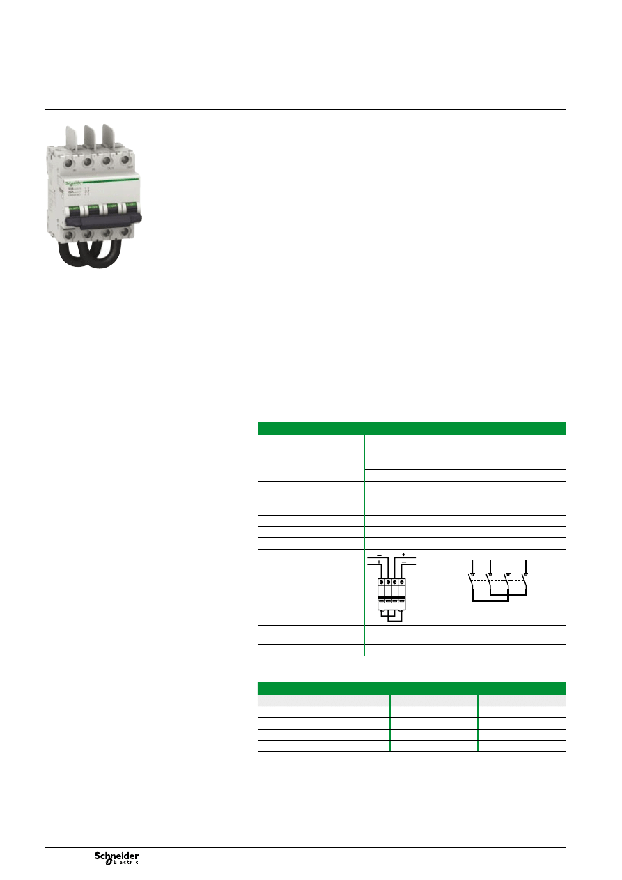
DC main switch for
photovoltaic installations
C60NA-DC
The C60NA-DC is a DC switch disconnector dedicated to array isolation and control
in photovoltaic installation with Voc until 650 V DC.
Associated with string protections devices (eg: C60PV-DC) it shall be installed in the
array box (see application diagram).
It isolates the PV field connected at the array to the rest of the PV field to allow
maintenance on PV string and PV string protections (eg: C60PV-DC or fuses).
It can be padlocked in off position to garantee safety interventions.
As fault current may flow in opposite direction of normal operating current,
C60NA-DC is able to switch multi directionnal current.
C60NA-DC is not polarity sensitive: (+) and (-) wires can inversed without any risk.
The C60NA-DC is:
compatible with C60 auxiliaries (MN, MX, OF, SD)
delivered with three inter-pole barrier to provide increased isolation distance
between two adjacent connectors.
IEC / EN 60947-3
e
b
b
Main characteristics
Operating voltage (Ue)
20 A: 650 V DC
30 A: 500 V DC
40 A: 400 V DC
50 A: 300 V DC
Rated insulation voltage (Ui)
1,000 V DC
Rated operational current (Ie) 50 A
Impulse voltage (Uimp)
6 kV
Electrical connection
By the top for In and Out
Number of poles
2P
Number of modules of 9 mm
8
Diagrams
1
2
4
3
IN
OUT
OUT
IN
1 3 2 4
1
2
4
3
IN
OUT
Standards
IEC 60947-3
EN 60947-3
Catalogue number
MGN61690
DB122704
Additional characteristics
Rating (A)
Voltage drop (mV)
Impedance (mΩ)
Power loss (W)
20 A
100
5.02
2
30 A
151
5.02
4.53
40 A
201
5.02
8.04
60 A
251
5.02
12.55
version: 1.2
CM901019E.indd
DB122506
PB105203-50
2
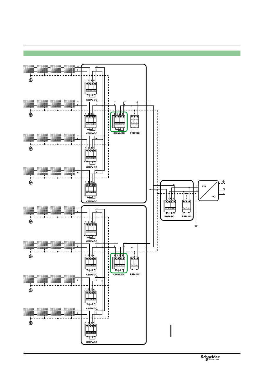
Applications
DC main switch for
photovoltaic installations
C60NA-DC (cont.)
When the PV array cable
exceeds 30 m, surge
arresters should be
connected at each end of
the cable, one set next to
the PV array, and the
other one next to the
power conditioning
device.
When the PV array cable
exceeds 30 m, surge
arresters should be
connected at each end of
the cable, one set next to
the PV array, and the
other one next to the
power conditioning
device.
Photovoltaic strings
Inverter
Junction box
Inverter protection
box
MN, MX, MNx, MNs, MSU,
MX+OF, OF, SD, OF+SD/OF
version: 1.2
CM901019E.indd
DB122496
3
DC main switch for
photovoltaic installations
C60NA-DC (cont.)
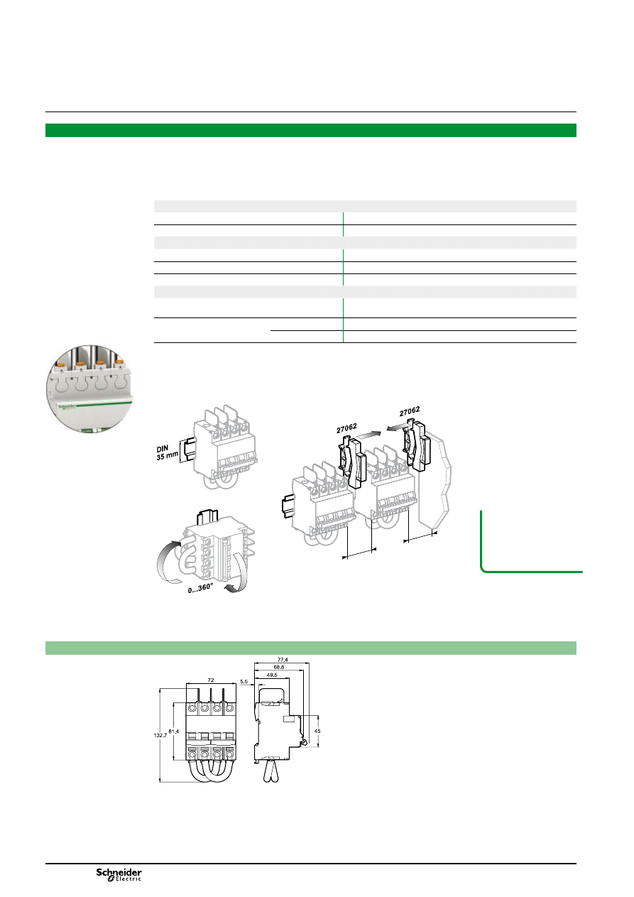
Technical data
Position contact indication - suitability for isolation according to IEC/EN 60947-3 standard.
The presence of the green strip guarantees physical opening of the contacts and allows operations to be
performed on the downstream circuit in complete safety.
Increased product service life thanks to fast closing independent of the speed of actuation of the toggle.
Pre-wired product: Input / Output on the same side.
b
b
b
b
Endurance (O-C)
Electrical
1,500 cycles
Mechanical
20,000 cycles
Complementary technical data
Degree of pollution
2
Category
DC21A
Weight
530 g / 18.69 oz
Environment
Tropicalisation
Relative humidity: 95 % at 55°C / 131°F in accordance with
IEC 60068-2 and GB 14048.2 standards
Temperature
Operating
-25°C to 70 °C / -13°F to 158°F
Storage
-40°C to 85°C / -40°F to 185°F
Moreover it is recommended to use:
a terminal Screw Shield snaps onto the front of the C60NA-DC protective devices to provide greater insulation
of the terminal screws
a Spacer clips 9 mm in each side to provide isolation.
b
b
Dimensions (mm)
C60NA-DC
DB122713
d
Required to have a
9 mm space
isolation in each
side"
version: 1.2
CM901019E.indd
DB122712
DB122715
DB122714
PB105208-29
9 mm
mini
9 mm
mini
4
DB122508
DC main switch for
photovoltaic installations
C60NA-DC (cont.)
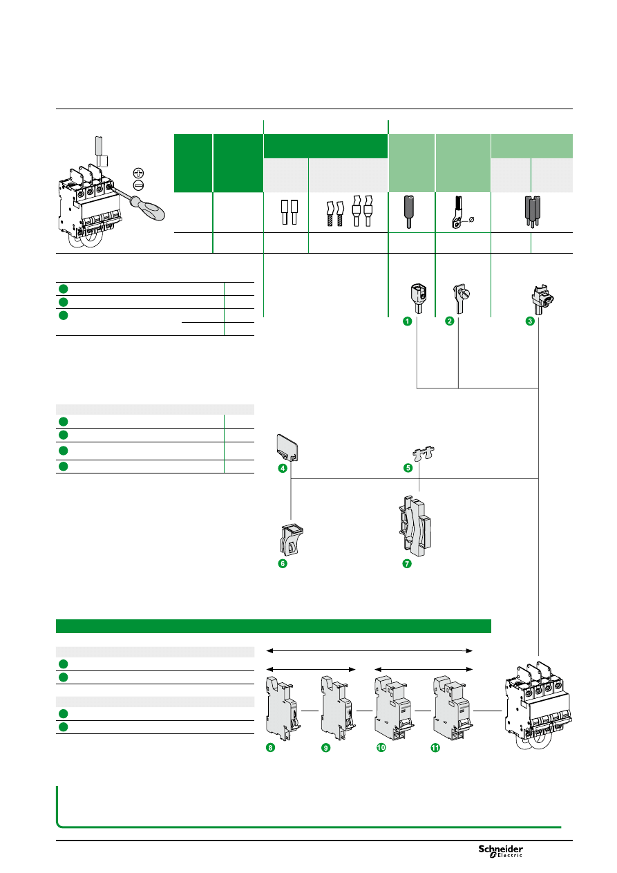
Indication
54 mm max.
Tripping
Connection
Without accessory With accessories
DB122701
Rating
Copper cables UL 486A
file no. #E216919
50 mm
2
Cu/Al
Terminal
Screw on
connection for
ring terminal
Multi-cables terminal
Rigids
Flexibles
with ferrule
Rigid
cables
Flexible
cables
50 A
3.5 N.m
1 to 35 mm
2
1 to 25 mm
2
50 mm
2
Ø 5 mm
3 x 16 mm
2
3 x 10 mm
2
DB1
12804
DB1
18756
DB1
18757
14 mm
PZ2
6.5 mm
1
Terminal 50 mm
2
Al / Cu
27060
2
Ring tongue terminal screw connection
27053
3
Insulated distribution terminal 4 pieces
19091
3 pieces
19096
Assembly
4
Inter-pole barrier
27001
5
Screw shield
26981
6
Padlocking accessory
(to be locked in the "open" position)
26970
7
Spacer
27062
C60 auxiliaries (see modules 90081 - 91103)
Indication
8
SD fault indicating switch
9
OF open/closed contact
Tripping
10
MN undervoltage release
11
MX + OF shunt release
DB1
12805
d
The electrical auxiliaries must be installed to the left of the circuit breaker and within a width of 54 mm.
If the auxiliary SD contacts are associated with the tripping auxiliaries (MN, MX, etc.), they must be installed to the left of
these auxiliaries.
DB1
18755
version: 1.2
CM901019E.indd
5
Wyszukiwarka
Podobne podstrony:
baterie sloneczne do produkcji energii elektrycznej
Energia ze słońca-Baterie słoneczne, Ogniwa i systemy fotowoltaiczne
Energia ze słońca-Baterie słoneczne, Ogniwa i systemy fotowoltaiczne
Baterie słoneczne
ZASADA DZIAŁANIA BATERII SŁONECZNYCH I EFEKT FOTOWOLTAICZNY, Chemia materiałów
Zegar na baterie słoneczne, ● EDUKACJA, TECHNIKA
Baterie słoneczne na drogach
4 a) Badanie baterii słonecznejzasada działania ogniwa fotowoltaicznego, MECHATRONIKA Szkoła, mechat
Referat Bateria słoneczna, Fizyka
Baterie słoneczne-ogniwa fotowoltaiczne, Baterie słoneczne-ogniwa fotowoltaiczne
Energia ze słońca-Baterie słoneczne, cennik doc, Szanowni Państwo
Moduł BMS PCM PCB ładowania i ochrony ogniw Li Ion 5S 18,4V 15A do ogniw 18650
Baterie słoneczne
trzecia generacja baterii slonecznych
Baterie słoneczne
jurkowski cw bateria słoneczna
więcej podobnych podstron