
SECTION 5
ELECTRICAL WIRING DIAGRAMS
5–2
W
ELECTRICAL WIRING DIAGRAMS
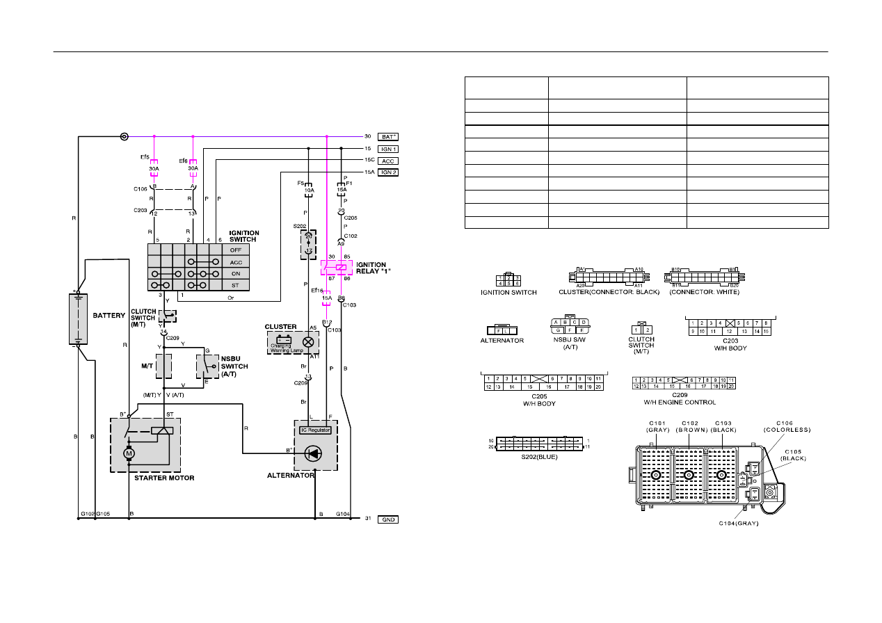
1. STARTING & CHARGING SYSTEM
1) BATTERY, IGNITION SWITCH, STARTER MOTOR, ALTERNATOR & SWITCH ( CLUTCH(M/T),
NSBU(A/T) )
a. CONNECTOR INFORMATION
CONNECTOR(NO)
(PIN NO. COLOR)
CONNECTING, WIRING HARNESS
CONNECTOR POSITION
C102(68 Pin, Brown)
Engine Room Fuse Box
Ĉ
Body
Engine Room Fuse Box
C103(68Pin, Black)
Engine Room Fuse Box
Ĉ
Engine Control
Engine Room Fuse Box
C106(2 Pin, Colorless)
Engine Room Fuse Box
Ĉ
Body
Engine Room Fuse Box
C203(15 Pin, White)
I.P
Ĉ
Body
Left Driver Leg Room Connector Holder
C205(20 Pin, Colorless)
I.P
Ĉ
Body
Right Driver Leg Room Connector Holder
C209(20 Pin, Colorless)
I/P
Ĉ
Engine Control
Upper Co–driver Right Kick Panel
S202(Blue)
IP
Upper Driver Leg Room
G102
Battery & ABS
Between Battery and Fuse Box
G104
Engine Control
Cylinder Head Next to #4 Intake Manifold
G105
Battery
Next to Starter Motor
b. CONNECTOR IDENTIFICATION SYMBOL & PIN NUMBER POSITION
ELECTRICAL WIRING DIAGRAMS
W
5–3
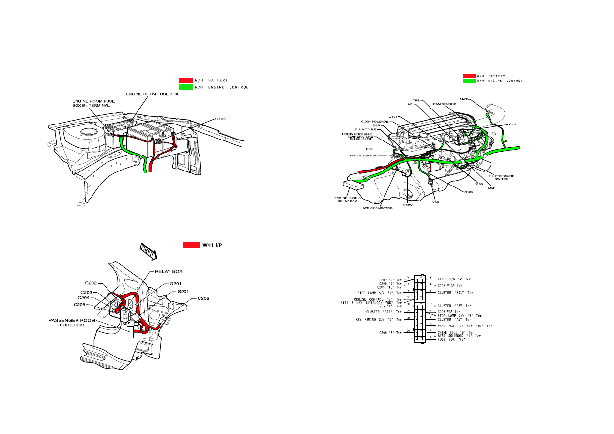
c. POSITION OF CONNECTORS AND GROUNDS
S
ENGINE ROOM FUSE BLOCK
S
LEFT ”A” PILLAR INSIDE
S
2.0 DOHC ENGINE
d. SPLICE PACK
S202 (BLUE)
Wyszukiwarka
Podobne podstrony:
NX650 T Section 20 Wiring diagram
WIRING DIAGRAMS FOR POWER SUPPLIES SECTION 3 7
NX650 T Section 20 Wiring diagram
BSA A10 wiring diagram id 93494 Nieznany (2)
How to Use the Electrical Wiring Diagram
Overall Electrical Wiring Diagram
77 WIRING DIAGRAM SYMBOLS
Overall Electrical Wiring Diagram
Mazda5 Wiring Diagram 1
67 SYSTEM WIRING DIAGRAMS
honda civic from 1991 to 1996 wiring diagrams 136 1
18 Wiring Diagram
BSA A10 wiring diagram id 93494 Nieznany (2)
G 2 0 DOHC ECS Wiring Diagram doc
wiring diagram symbols
21 Wiring Diagrams
wiring diagram 3 4 cyl SMART LPG
ignition wiring basic wiring diagram BRIGGS & STRATTON
Wiring Diagrams
więcej podobnych podstron