
Safety Precautions
Photovoltaic Modules will be “live” upon exposure to light. There will be a voltage present on the
output terminals. This voltage will vary according to the type of the photovoltaic module. The
array will generate voltages substantially higher than the system nominal voltage, thereby resulting
in a shock hazard. This hazard may be minimized by completely shading the array before making
these connections.
Extreme care should be exercised when working with batteries. Batteries contain a high discharge
current capacity and caustic compounds are present. Sparks, flames, smoking materials, etc. can
ignite the gases of some batteries. Eyes, face, and hands should be protected. Tools should be
used with care.
Carefully read the installation instructions before attempting to electrically connect any part of the
power system. Most charge controllers are permanently damaged if the battery polarity is reversed
when it is connected the controller.
1
2
3
5
6
4
1.0
Solar Array Wiring
Solar modules Direct mount and Multi mount frames have cords attached to them. These cords
contain a red and black wire. Red is the positive and black is the negative.
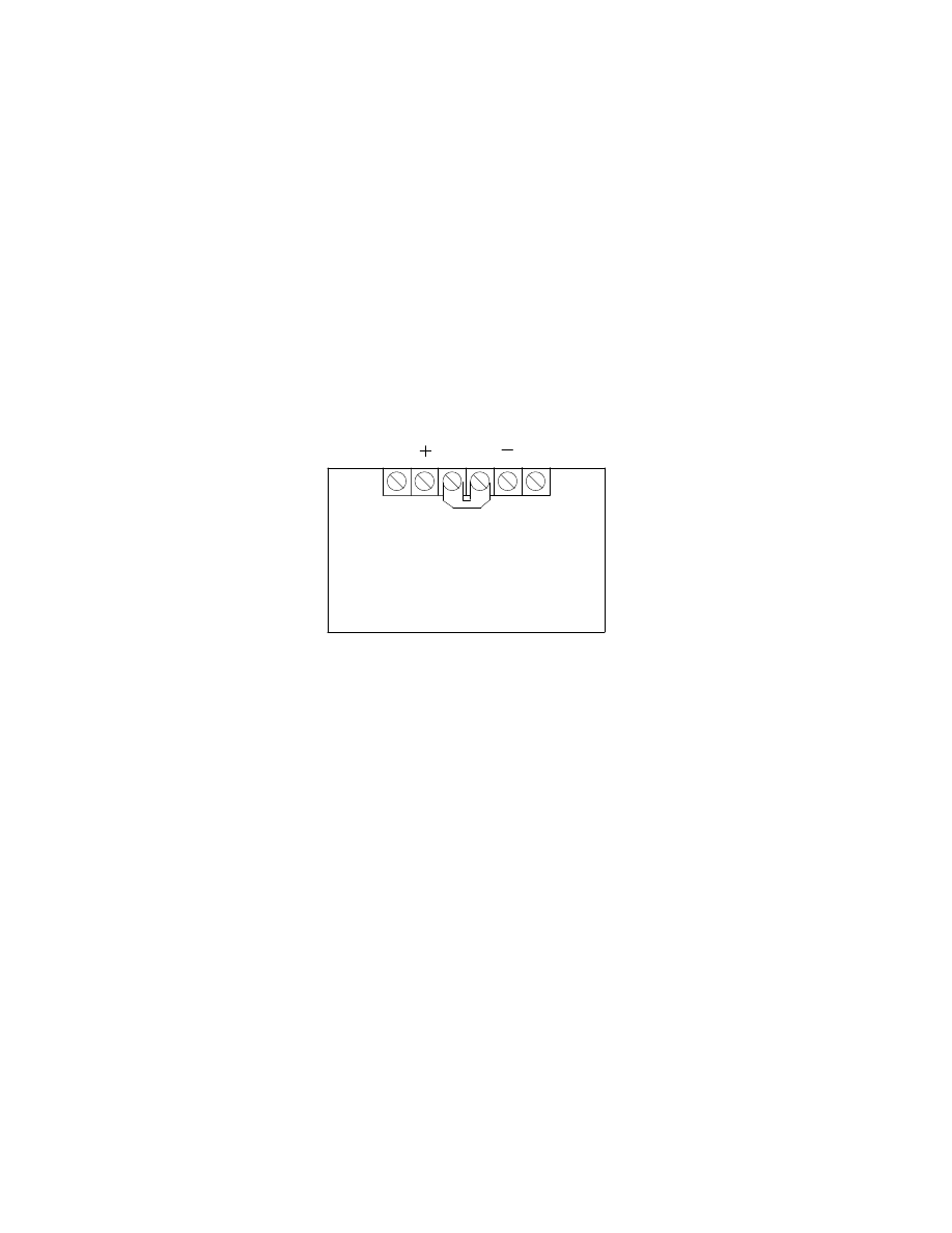
Solar Modules with Universal frames have junction boxes. Inside the junction box is a terminal
strip.
The terminals of the terminal strip are identified as the following. #1 & #6 are unused terminals.
They are typically used in large arrays to feed wire through the junction box. Terminal #2 is 12
volts positive. Terminal #5 is 12 volts negative.
1.1
12 Volt BP Solar (Solarex) Wiring
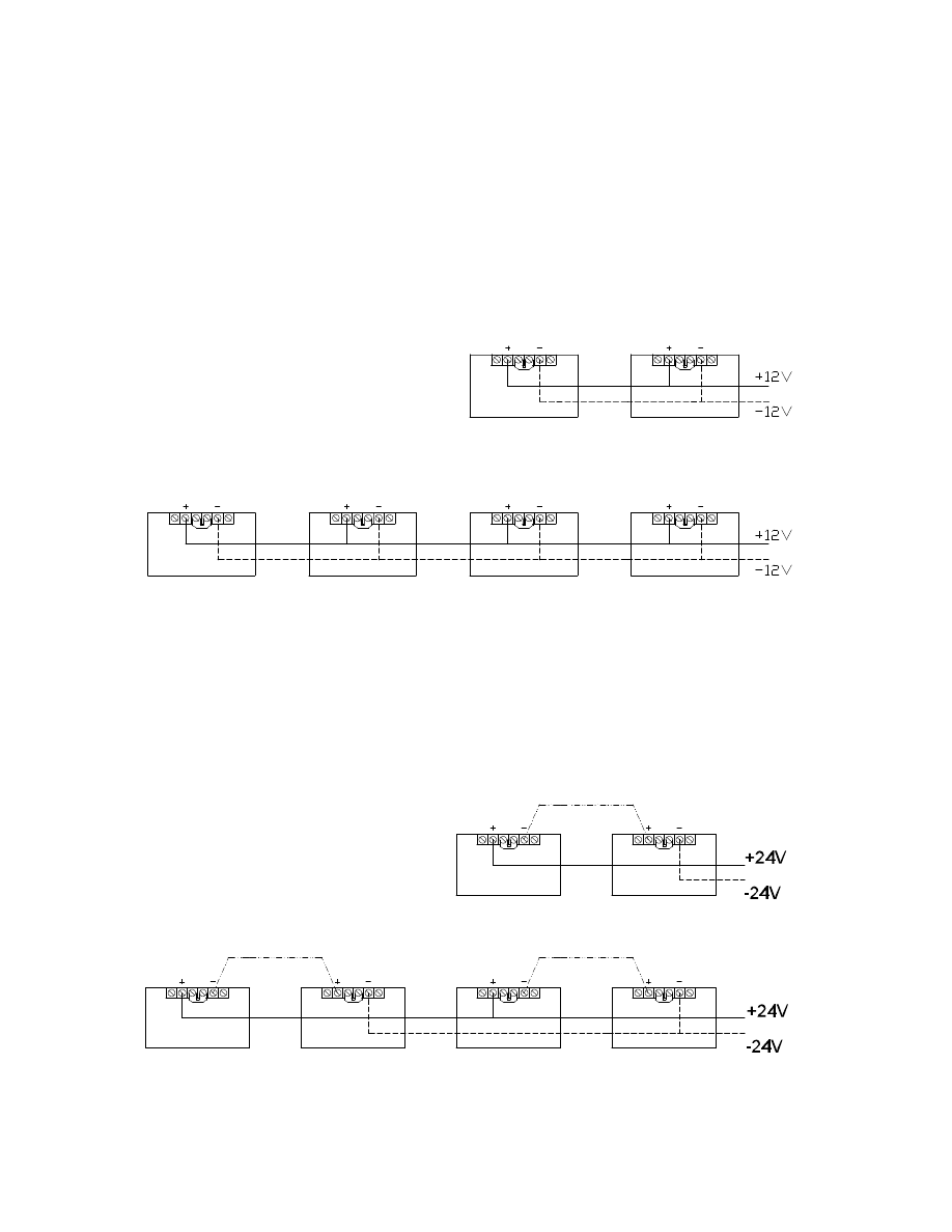
12 volt solar arrays are wired in parallel increasing their current output. For example, if two 12V
3.5A modules are wired in parallel the total solar array output will be 7A @ 12V.
1.2
24 Volt BP Solar (Solarex) Wiring
24 volt solar arrays are wired in series increasing their voltage output. For example, if two 12V
3.5A modules are wired in series the total solar array output will be 3.5A @ 24V. These series
sets of modules can then be wired in parallel to increase the current output of the solar array. For
example, if four 12V 3.5A modules are wired in a series\parallel combination the total solar array
output will be 7A @ 24V.
1.3
48 Volt BP Solar (Solarex) Wiring
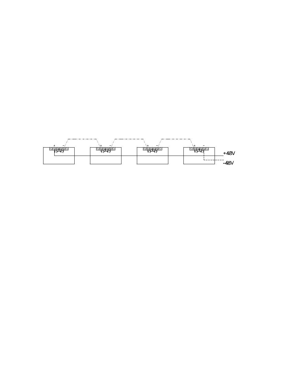
48 volt solar arrays are wired in series increasing their voltage output. For example, if four 12V
3.5A modules are wired in series the total solar array output will be 3.5A @ 48V. These series
sets of modules can then be wired in parallel to increase the current output of the solar array. For
example, if eight 12V 3.5A modules are wired in a series\parallel combination the total solar array
output will be 7A @ 48V. Please note the addition of bypass diodes in the 48V solar array. Do
not install a 48V solar array without these diodes. Please read section 1.4 for greater detail.
1.4
Bypass Diodes
In solar arrays over 24V bypass diodes must be installed to protect the solar cells.
Bypass diodes, also known as shunt diodes, are used in photovoltaic arrays to allow for current to
flow around cells or modules that for one reason or another (usually shadowing) are producing
less current than the others in a series connected string. There are two reasons that this
"bypassing" of shadowed (or damaged) cells and modules is desirable. First, it may be possible to
still obtain some useful output from the string of cells or modules even if one or more cells or
modules is shaded. Second, in some systems enough voltage is present to force current to flow
even through a damaged or shadowed cell. This can force the shadowed or damaged cell to
dissipate a large amount of power resulting in localized heating with potentially catastrophic
effects such as melting interconnects and charring and burning of the encapsulant. This is clearly
a safety issue and is the main reason that bypass diodes are required on higher (>24 V) voltage
systems.
All large modules have been designed for multiple series connections to accommodate a bypass
diode every 18 cells. This is the principal reason for the dual voltage four terminal output found
on all BP Solar (Solarex) large power modules. The voltage built up across 18 cells is insufficient
to damage a cell even under extreme conditions of temperature and shadowing. Using larger
numbers of cells between diodes allows for substantially more voltage to build up creating more
heat and possibly resulting in module failure under worst case conditions.

The bypass diodes are installed at the manufactured in every large module. Although diodes are
relatively reliable they can still fail. When they do fail it’s usually in a shorted or conducting
condition. This kind of failure in a bypass diode would result in the entire string of "protected"
cells being shorted out and contributing no power to the array.
1.5
Blocking Diodes
Blocking diodes are different then bypass diodes. The diode in most cases is physically the same.
However it is installed differently and serves a different purpose.
A blocking diode only allows current to flow in one direction. If you have a charge controller in
your system you do not need a blocking diode to prevent the solar module from discharging the
battery at night. All charge controllers have night time discharge protection built into them.
Adding a diode with a charge controller to prevent battery discharge at night is redundant and will
consume power from your array during the day.
The only time a blocking diode is used is when you have an array of 2 or more modules and the
array is partially shaded. When a solar module is partially shaded its power output is drastically
effected. If this module is connected to another solar module. The output of both modules will be
effected even if only one of the two modules is shaded.
If you have an array with a shadow that passes over the modules one module at a time it is
recommended that a blocking diode be added to each module. An example of this might be a pole
that is in front of the array. The shadow is small and will move over the array as the sun moves
through the sky.
If the array is totally shaded at approximately the same the day then adding a diode will most
likely consume more power then it will save you. For example, if your array a large full tree that
casts a shadow on the total array. I would look at relocating the array or trimming the tree before
adding a blocking diode to the system.
+24V
-24V
-48V
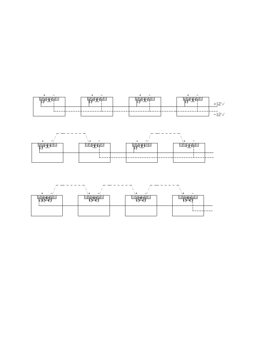
1.6
Example Wiring with Blocking Diodes
Wyszukiwarka
Podobne podstrony:
solar power qa
Adding Solar Power
Solar Power Overview
Concentrating Solar Power Energy From Mirrors
[ebook renewable energy] Home Power Magazine 'Correct Solar Panel Tilt Angle to Sun'
[ebook renewable energy] Home Power Magazine 'Correct Solar Panel Tilt Angle to Sun'
Ch05 Wiring&Power
Home Power Magazine 012 Aug Sep 1989 Renewable Solar Wind Energy
Home Power Magazine Issue 072 Extract p34 Solar Hot Air Collectors
Home Power Magazine 024 Extract p26 p30 All Solar Panels Ever Tested
Home Power Magazine Issue 109 Extract pg22 Making Sense of Solar Electricity Costs
WIRING DIAGRAMS FOR POWER SUPPLIES SECTION 3 7
Home Power Magazine 007 Oct Nov 1988 Renewable Solar Wind Energy
Home Power Magazine Extract Installation Basics For Solar Domestic Water Heating Systems Part 2
Alternative Energy Technologies, Solar and Wind Power Systems
Home Power Magazine Issue 063 Extract p42 Solar charge controller for Medium Power Applications
Home Power Magazine 003 Feb 1988 Renewable Solar Wind Energy
Battery Power for Your Residential Solar Electric System
więcej podobnych podstron