Electronics
Semiconductor Division
Introduction
A flicker-free PC-to-TV encoding is demonstrated on the
TMC2360P7CKL evaluation board. Mounted on the
TMC2360P7CKL board is a TMC2360KLC part (80-pin
MQFP). With an external VGA source, either +5 or +9 volt
power, and a TV monitor, TMC2360 performance can be
evaluated.
Although the TMC2360 can operate with a minimum of
external components, included on the board are a number of
options such as alternate clocks, a microprocessor interface
and x/sinx filters that allow various configuration options to
be explored.
Kit Contents
Within the evaluation kit are seven items:
• TMC2360 MQFP demo board
• TMC236X Software
• Power brick
• S-video cable (Y/C)
• Composite video cable (RCA)
• VGA cable
• Instructions document
Quick Setup for NTSC
1.
Install jumpers JP13 (if oscillator), 14 (if crystal), 20
and 21.
2.
Set DIP switches CVIDEN
→
OFF, SVIDEN
→
OFF,
PWRDN
→
OFF, TVSTD0
→
OFF and all other DIP
switches
→
ON.
3.
Connect a 640*480/60 Hz VGA source to J7.
4.
Connect J4 to VGA monitor. (optional)
5.
Connect either RCA-type video cable from connector J1
or S-video cable from J3 to TV monitor.
6.
Connect 5
±
0.2 Volt/ 0.5 amp DC source to connector J6
(see PWB silk-screen for polarity) or 9 volt/0.5 amp DC
supply to connector J8.
7.
Observe images on VGA monitor and TV monitor.
Quick Setup for PAL
Repeat
Quick Setup for NTSC
except:
1.
Set VGA source to 640*480/50 Hz.
2.
Set DIP switch TVSTD1
→
OFF and TVSTD0
→
ON
Operational Information
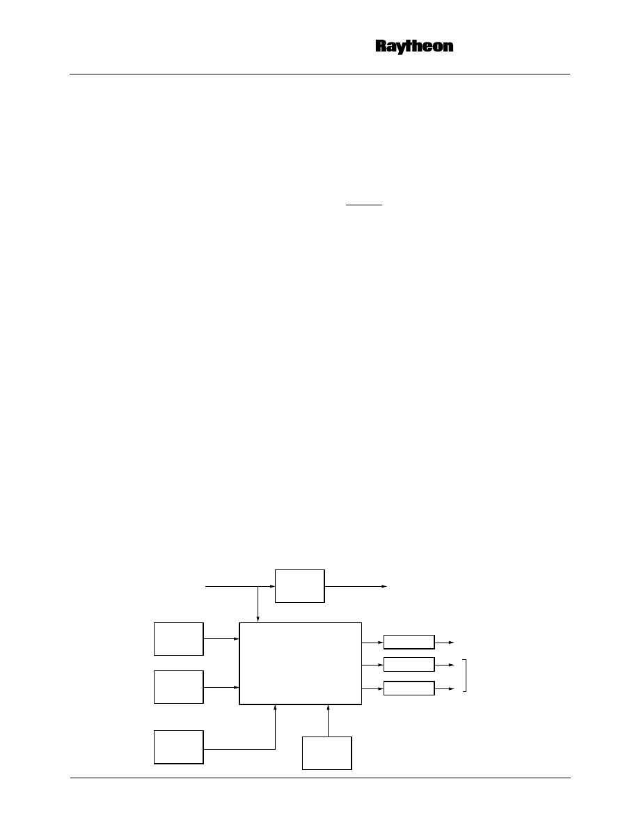
In its basic configuration, the TMC2360P7CKL Evaluation
Board is intended to demonstrate how the TMC2360 can be
used to convert VGA video to TV video with a minimum
TMC2360P7CKL
Video Output Processor Evaluation Kit
Block Diagram
RGB
Buffers
Controls
Setup
Switches
Micro-
processor
Interface
Power
Distribution
Filter
Filter
Filter
Y
C
TMC2360
VGA-to-Video
Converter
VGA Input
VGA Output
Composite
Video Output
S-Video
Output
Rev. 1.0.1

TMC2360P7CKL
PRODUCT SPECIFICATION
2
number of external components. Extra components are
included on the board to permit evaluation of alternate con-
figurations such as external clocks and the microprocessor
interface.
Basic Configuration
In this configuration, install the following jumpers (see Table 1):
• JP13 (if oscillator)
• JP14 (if crystal)
• JP15 (if crystal)
• JP20
• JP21
Note that JP1, JP2, JP3, JP9, JP10, JP11 are pre-installed at
the factory.
In addition, remove the following jumpers:
• JP4
• JP5
• JP6
• JP7
• JP8
• JP12
• JP13 (if crystal)
• JP14 (if oscillator)
• JP15 (if oscillator)
Note that JP16, JP17, JP18 are open circuit from factory.
All switch and push-button functions are available. Either of
two power sources may be used. With JP19 removed, +5
volt power may be connected directly to connector J6. Alter-
natively, with JP19 installed, 9 volt power may be connected
via the 2.1 mm jack, J8.
Image attributes may be controlled by three switches:
• PHASE optimizes VGA data sampling by inverting the
internal ADCLK of the TMC2360.
• BLANK blanks the image to the color set by BLUE.
• BLUE = OFF sets the blank color to blue. BLUE = ON
sets the blank color to black.
Switches TVSTD0 and TVSTD1 allow one of four output
standards to be selected:
Switch PAL800
→
OFF sets timing and clocks for
conversion of 50Hz 800x600 pixel VGA images.
Supplied with the board is a 27 MHz oscillator, Y1 or a 27
MHz crystal Y2. JP13 or JP14 and JP15 must be installed to
select the correct source. With JP13, 14, and 15 removed
and JP12 installed, the TMC2360 clock may be supplied
from an external 27 MHz source connected to J5.
Power Management may be implemented through three
switches:
• CVIDEN = OFF enables the composite video output.
• SVIDEN = OFF enables the S-Video output.
• PWRDN = OFF powers down the TMC2360 into a sleep
mode.
Software control through VGA sync signals is enabled by
two switches:
• DPMS = OFF enables display power management.
Missing HSYNC or VSYNC signals will blank the screen
and/or power down the TMC2360. (see data sheet)
• VSCOM = OFF enables vertical sync communications.
The number of HSYNC pulses per vertical sync period
will set the TV standard and the filter mode. (see data
sheet)
Optional Configurations
Optional configurations are programmed by installing jump-
ers (see Table 1) and by use of alternate connections (see
Table 2).
JP12, 13, 14 and 15, allow the 27 MHz clock to be sourced
from either a board mounted oscillator or crystal or an exter-
nal clock.
To access the VGA registers through the microprocessor
port, the MPEN switch must be set OFF. For microprocessor
programming information refer to the TMC2360 data sheet.
Contact Raytheon Electronics
for a schematic and PAL
equations for a simple programming tool.
For probing without an external TV monitor connected, JP4,
6 and 7 add 75
Ω
loads to the filter outputs.
Connectors J6 and J8 allow connection of either 9 volt DC or
5 volt DC power.
J1 and J3 allow connection of either composite or S-Video
(Y/C) to a TV monitor.
TVSTD
1-0
Television Standard
00
NTSC-EIAJ
01
NTSC
10
PAL/B, G, I
11
PAL/M

PRODUCT SPECIFICATION
TMC2360P7CKL
3
Table 1. Jumpers
Table 2. Connectors
Jumper
Function (when installed)
JP1
Connects composite video filter output to J1
JP2
Connects luminance video filter output to J3
JP3
Connects chrominance video filter output to J3
JP4
Adds 75
Ω
load to Composite Video Filter Output
JP5
Adds 75
Ω
load to Luminance Video Filter Output
JP6
Adds 75
Ω
load to Chrominance Video Filter Output
JP7
Enables ADCLK from external phase-locked loop controller
JP8
Enables PXCK from external phase-locked loop controller
JP9
Connects COMP output to composite video filter
JP10
Connects LUMA output to luminance filter for S-video
JP11
Connects CHROMA output to chrominance filter for S-video
JP12
Connects external 27 MHz clock source to XTAL1 input
JP13
Connects 27 MHz Crystal Oscillator to XTAL1 input
JP14
Connects 27 MHz Crystal to XTAL1 input
JP15
Connects 27 MHz Crystal to XTAL2 input
JP16
Bypass L12
JP17
Bypass L13
JP18
Bypass L14
JP19
Connects V
CC
to voltage regulator if external 9 volt DC power is used
JP20
Connect VGA vertical drive, VIN to VGAVS input
JP21
Connect VGA horizontal drive, HIN to VGAHS input
Reference
Designator
Function
J1
RCA jack, composite video output
J2
Header for probing XTL27, PXCK and ADCLK clocks
J3
S-video output jack
J4
VGA Out, 15-pin D-Sug
J5
BNC to accept optional external 27 MHz XTAL clock
J6
+5
±
0.2 Volt DC regulated power input
J7
VGA In, 15-pin D-Sug
J8
Accepts 9
±
1 volt DC unregulated external power from 2.1 mm. plug
P1
Microprocessor Interface Connector

TMC2360P7CKL
PRODUCT SPECIFICATION
4
Table 3. Switches
Table 4. Pushbuttons
Reference
Designator
Acronym
Function
ON
OFF
S5
CVIDEN
Disable Video Output
Enable Video Output
SVIDEN
Disable S-Video Output
Enable S-Video Output
PWRDN
Power down TMC2360
Activate TMC2360
MPEN
Disable Microprocessor Port
Enable Microprocessor Port
S6
PHASE
Sample clock non-inverted
Image displaced 1/2 pixel left
TVSTD1
TV Standard bit 1 = L
TV Standard bit 1 = H
TVSTD0
TV Standard bit 0 = L
TV Standard bit 0 = H
PAL800
Disable PAL800 mode
Enable PAL800 mode
S7
BLUE
If BLANK switch is OFF, screen blanked
to black.
If BLANK switch is OFF, screen blanked
to blue.
BLANK
Video enabled.
Video output blanked
VSCOM
Disable Vertical Sync Communications
Enable Vertical Sync Communications
DPMS
Disable Display Power Management
Enable Display Power Management
Reference
Acronym
Function
S1
FIL
Filter Select
S2
POSR
Position Right
S3
POSD
Position Down
S4
RESET
Reset TMC2360
Theory of Operation
Power and Grounds
Power may be derived from an external AC/DC module with
a 9 volt/700 mA output. Alternatively, if jumper JP19 is
removed, a 5 volt/700 mA DC supply may be connected
directly to the internal +5 volt bus via connector J8.
A common ground plane is used for both analog and digital
signals. But notice that the routing of analog/analog/digital
traces over the plane is carefully segregated. Digital and
analog traces are not mixed and critical circuits such as PLL
filters and crystal oscillator components are separated from
other circuits.
Power is also segregated. V
DD
to the analog and digital
sections is derived from a common source but isolated by
ferrite beads. Three other isolated power lines supply the
phase locked loops and VGA emitter followers. Note that
VDDD and VDDA have a common 22
µ
F decoupling
capacitor to support hefty current surges.
VGA Interfaces
VGA signals from a 15-pin D-Sub connector, J7 are looped
through the board to a VGA output connector, J4. Video
signals are buffered by three PNP emitter followers which
elevate the video level from a nominal 0 - 0.7 volt to 0.6 - 1.3
volt.
Horizontal and vertical sync signals from J7 are routed
through the TMC2360 to J4. RGB inputs from J7 flow
through a low pass filter prior to digitization in the
TMC2360.
User Controls
Three push-buttons control the TMC2360 video output :
• POSR - position right in eight pixel increments reversing
extreme right and left positions.
• POSD - position down in eight line increments reversing
at extreme down and up positions.
• FIL - Select either one, two or three line vertical filtering
trading off smearing of the image against flicker
reduction.
One other control is included for engineering evaluation:
• RESET clears all internal registers, setting the vertical
filter to the three line mode and positioning the TV image
at the center.

PRODUCT SPECIFICATION
TMC2360P7CKL
5
Setup Switches
For most applications, these switches are preset according to
the functions defined in the TMC2360 data sheet. Switch
Mnemonics are silk-screened on the PWB beside each
switch.
A/D Converter Reference Voltage
Top voltage for the RGB A/D converters, V
T
is supplied by
the output V
TOUT
of a buffer amplifier with input V
TIN
connected to potentiometer VR2. Reference voltage for VR2
is derived from the 1.235 volt R
REF
voltage.
Nominally, V
RT
is set at 0.85 volts, just above the 0.7 volt
VGA video amplitude but can be adjusted lower for attenu-
ated inputs or increased to improve digitization if inputs are
amplified.
D/A Converter Current
Resistance from R
REF
to ground sets the video output
current. Potentiometer VR1 allows trimming of the output
video amplitude.
With a 392
Ω
resistor connected to R
REF
, the D/A current is
27 mA. (1 volt across 37.5
Ω
) at 100 IRE units.
Phase Locked Loop Filters
A/D converter and encoder phase locked loop filters are
identical. Each filter is driven by a charge pump (peak cur-
rent Ip) to generate a voltage across the filter network which
drives the voltage controlled oscillator. Derivation of the fil-
ter parameters without a divide-by-N counter in the feedback
loop can be can be found in Gardner.
*
Figure 1. Phase locked Loop Block Diagram
With the divide-by-N counter, the performance is given by:
Natural frequency,
ω
n
=
Damping factor,
ξ
= (RC/2)
*.
where, for the TMC2360:
Ip = 100 microamps
K
0
= 2
π
10 Mrad/volt
For R = 39 K
Ω
and C = 0.1
µ
F:
f
n
=
ω
n
/2
π
= 563 Hz
ξ
= 6.9
27 MHz Oscillator
A 27 MHz reference signal is supplied to the TMC2360 for
the encoder subcarrier synthesizer. This signal may be
derived from one of three sources:
• An oscillator connected to XTAL
1
, (JP13),
• A crystal connected across XTAL
1
and XTAL
2
,
(JP14,15),
• An external generator connected to J5, (JP13).
Crystal frequency can be trimmed by adding capacitors or
changing the 47 pF capacitors shown. Typical pull-in
sensitivity for the crystal is 15 ppm/pF.
Microprocessor Port
TMC2360 VGA registers can be accessed through a micro-
processor port which bypasses parameters entered via the ten
external setup switches. Each line is pulled low by a 47K
resistor. Setting MPEN = H enables the port. Register
addresses, bit functions and timing diagrams are included in
the TMC2360 data sheet.
Output Filters
Antialiasing filter design is simplified by operating the three
TMC2360 D/A converters in a 2x over-sampling mode. A
filter is included in each video output channel to limit the
video bandwidth to 10 MHz and provide sinx/x correction.
With a group delay of 30 nanoseconds across the pass-band,
each filter is close to linear phase.
Figure 2. Video Filter Response
VCO
(K
0
)
1/N
Phase
Detector and
Charge Pump
Ip
4074 02
R
C
θ
i
θ
o/N
θ
o
K
0
I
P
2
π
CN
⁄
(
)
K
0
I
P
2
π
CN
⁄
(
)
10.00
0.00
-10.00
-20.00
-30.00
-40.00
1
10
Frequency (MHz)
Gain (dB)
100
4074 03
*F. M. Gardner, “Charge-Pump Phase-Lock Loops”,
IEEE Trans on
Communications
, Vol. COM-28, No. 11, November 1980.

TMC2360P7CKL
PRODUCT SPECIFICATION
6
J8
CHRG
EXT PWR
GND
TP16
LOOP
JP19
VCC
VDDD
VDDA
VDDPLLD
VDDPLLE
JUMPER
C40
22
+
U4
LM7805CT
L7
BEAD
D1
LED
GREEN
1
1
IN
OUT
3
2
2
C42
0.1
C23
0.1
C39
0.1
C27
0.1
L15
BEAD
C33
0.1
R28
100
C41
0.1
R25
100
C37
0.1
C17
22
NOTE: LED has integral resistor for 5V operation
+
C38
0.1
C43
0.1
C31
0.1
J6
2
1
1
2
Printed Wiring Board Layout
Circuits are implemented on a four layer printed wiring
board. Interconnects are on layers one and four. Ground is a
continuous plane on layer three and power on layer four is
split into sections for the digital analog and phase-locked
loop sections of the TMC2360. Traces are carefully
segregated to avoid crosstalk. Each analog connection is run
over a continuous ground plane and treated as a transmission
line.
For details of layout and interconnection techniques contact
Raytheon Electronics
for copies of artwork.
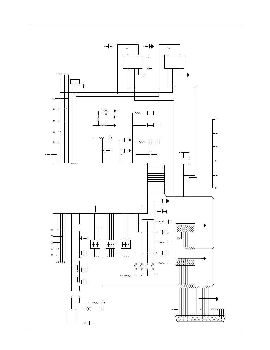
Schematics
TMC2360P7CKL Evaluation Board

PRODUCT SPECIFICATION
TMC2360P7CKL
7
TMC2360P7CKL Evaluation Board
WIRE JMPR
L12
BEAD
L8
BEAD
R17
75
R12
220
C20
47 pF
ROUT
GOUT
BOUT
HDOUT
VDOUT
1
2
3
4
5
6
7
8
9
10
11
12
13
14
15
J4
DB15S
3-ROW
1
2
3
4
5
6
7
8
9
10
11
12
13
14
15
RIN
GIN
BIN
J7
DB15P
3-ROW
RINF
GINF
BINF
Q1
PNP
R16
100
R22
150
VA
JP16
WIRE JMPR
L13
BEAD
L9
BEAD
R19
75
R13
220
C19
47 pF
C24
0.1
C25
0.1
C26
0.1
VA
VCC
L11
BEAD
Q2
PNP
R18
100
R23
150
VA
JP21
JUMPER
JP20
JUMPER
HIN
VIN
JP17
WIRE JMPR
L14
BEAD
L10
BEAD
R21
75
R14
220
C18
47 pF
HDIN
VDIN
Q3
PNP
R20
100
R24
150
VA
HDOUT
VDOUT
JP18
TP16
LOOP
TMC2360P7CKL
PRODUCT SPECIFICATION
8
TMC2360P7CKL Evaluation Board
R
G
B
VGAHS
VGAVS
CBYPR
VSOUT
HSOUT
77
26
27
C32
0.1
LUMA
CHROMA
COMPOSITE
80
78
2
VDOUT
HDOUT
LUMA
CHROMA
COMP.
J2
HDR4
PXCK
HDOUT
PDIVM
ADCLK
VDDA
VDDA
VDD
U2
AV9173
HDOUT
ADVIN
1
2
3
4
XTL27
PXCK
ADCLK
11
12
13
R_REF
3
VTIN
57
V_REF
VTOUT
VRT
4
58
55
C14
680 pF
C22
0.1
VDDA
C21
0.1
C44
0.1
C45
0.1
VR2
10K
R11
750
R10
412
VR1
5K
3
1
2
2
1
3
C28
0.1
Note: If Microprocessor Interface is not used,
connect pins ADIVN .. R/W to ground and CE
to VDDD.
C16
0.1
C13
680 pF
C15
0.1
R27
39K
R26
39K
LPFA
5
2
8
6
1
4
OE
IN
FBIN
FS0
CLK2
CLK1
U2
AV9173
5
2
8
6
1
4
OE
IN
FBIN
FS0
CLK2
CLK1
64
LPFP
67
RINF
GINF
BINF
HDIN
VDIN
JP13
VDDA
VCC
Y1
27MHz
R32
4.7K
R29
47.5K
RN2
47K
RN1
47K
C46
0.1
R30
47.5K
C47
0.1
R31
47.5K
C48
0.1
D8
D9
A0
A1
Enable external PXCK
Enable external ADCLK
C49
0.1
FIL
POSR
POSD
D[7..0]
RESET
Y2
27MHz
R15
50
C29
5.6 PFS
NPO
C34
47 PFS
NPO
C35
47 PFS
NPO
C36
5.6 PFS
NPO
OUT
5
C30
0.1
J5
BNC
1
1
1
1
2
JP14
JP15
S1 PB
JP8
JP7
VDDD
S2 PB
S3 PB
S4 PB
VCC
P1
DB25
SW DIP-4
SW DIP-4
SW DIP-4
JP12
JUMPER
59
53
50
48
45
1
2
3
4
8
7
6
5
1
2
3
4
8
7
6
5
1
2
3
4
74
73
72
37
38
44
43
6
39
40
41
42
47
48
71
13
25
12
24
11
23
10
22
9
21
8
20
7
19
6
18
5
17
4
16
3
15
2
14
1
D0
D1
D2
D3
D4
D5
D6
D7
D8
D9
D8
D7
D6
D5
D4
D3
D2
D1
D0
34
33
32
31
30
25
24
23
22
21
20
19
18
17
16
CE-
RW
A0
A1
MPEN
D0
D1
D2
D3
D4
D5
D6
D7
D8
D9
CE
R/W
A0
A1
MPEN
D0
D1
D2
D3
D4
D5
D6
D7
PDVIM
ADIVM
RW
CE-
A1
A0
MPEN
D9
10
9
8
7
6
5
4
3
2
10
9
8
7
6
5
4
3
2
A0
A1
RW
CE-
PDIVM
ADIVN
D[7..0]
VSS
GNDPLLE
GNDPLLD
GNDA
1
1
CVIDEN
SVIDEN
PWRDN
BLUE
BLANK
VSCOM
DPMS
PHASE
TVSTD_1
TVSTD_0
PAL800
FIL
POS_R
POS_D
RESET
8
7
6
5
CVIDEN
SVIDEN
PWRDN-
MPEN
BLUE
BLANK
VSCOM
DPMS
PHASE
TVSTD1
TVSTD0
PAL800
S5
S7
S6
70
69
XTAL_1
XTAL_2
TMC2360KL
U3
VDDA
TP5
VDOUT
TP6
HDOUT
TP8
LUMA
TP9
CHROMA
TP7
COMP.
TP10
R
TP11
G
TP12
B
TP15
HS
TP13
VS
GNDD

PRODUCT SPECIFICATION
TMC2360P7CKL
9
TMC2360P7CKL Evaluation Board
LUMA
1
2
3
4
J3
JP2
WIREJMPR
JP10
WIREJMPR
JP3
TP4
CHROMA
TP3
LUMA
VCC
D3
MBR0540
C4
330 pF
C9
330 pF
R5
75
L5
1.0
µ
H
R8
75
C10
100
µ
H
CHROMA
COMPOSITE VIDEO
JP11
WIREJMPR
VCC
D5
MBR0540
C6
330 pF
C11
330 pF
R6
75
L6
1.0
µ
H
R9
75
C12
100PF
R2
75
R3
75
R1
75
JP4
75 OHM
JP5
75 OHM
JP6
75 OHM
C3
27 pF
C5
27 pF
L2
1.8
µ
H
L3
1.8
µ
H
COMP
JP9
WIREJMPR
VCC
TP14
LOOP
TP2
COMP
D5
MBR0540
C2
330 pF
C7
330 pF
R4
75
L4
1.0
µ
H
R7
75
C8
100PF
C5
27 pF
L3
1.8
µ
H
WIREJMPR
JP1
J1
RCA
1
2
WIREJMPR
SVID
S-VIDEO

TMC2360P7CKL
PRODUCT SPECIFICATION
10
Parts List
Item
Qty.
Part-Name
Reference-Designator
Description
1
2
4310R-101-473
Bourns
RN1 RN2
47K
Ω
2
2
RJ26FW502
Mepcopal
VR1 VR2
5K
Ω
3
1
RN50C49R9F
R15
50
Ω
1%
4
12
RN50C75R0F
R1 R2 R3 R4 R5 R6 R7 R8
R9 R17 R19 R21
75
Ω
1%
5
5
RN50C1000F
R16 R18 R20 R25 R28
100
Ω
1%
6
3
RN50C1500F
R22 R23 R24
150
Ω
1%
7
3
RN50C2210F
R12 R13 R14
221
Ω
1%
8
1
RN50C4750F
R10
475
Ω
1%
9
1
RN50C7500F
R11
750
Ω
1%
10
1
RN50C4751F
R32
4.75K
Ω
1%
11
2
RN50C3922F
R26 R27
39.2K
Ω
1%
12
3
RN50C4752F
R29 R30 R31
47.5K
Ω
1%
13
3
SR151A270JAA
AVX
C1 C3 C5
27 pF 5% NPO
14
3
SR151A470JAA
AVX
C18 C19 C20
47 pF 5% NPO
15
3
SR151A101JAA
AVX
C8 C10 C12
100 pF 5% NPO
16
6
SR151A331JAA
AVX
C2 C4 C6 C7 C9 C11
330 pF 5% NPO
17
2
SR151A680JAA
AVX
C13 C14
680 pF 5% NPO
18
2
SR215C104JAA
AVX
C15 C16
0.1
µ
F 5%
19
27
12065C104KATMA
AVX
C21 C22 C23 C24 C25 C26
C27 C28 C30 C31 C32 C33
C37 C38 C39 C41 C42 C43
C44 C45 C46 C47 C48 C49
0.1
µ
F
20
2
TAP226K035HSB, AVX
C17, C40
22
µ
F, 35v Tantalum
21
2
TBD
C29 C36
Not Installed
22
2
TBD
C34 C35
Not Installed
23
3
IMS-2 1.8
µ
H 5%
Dale
L4 L5 L6
1.0
µ
H 5% Shielded Inductor
24
3
IMS-2 1.0
µ
H 5%
Dale
L1 L2 L3
1.8
µ
H 5% Shielded Inductor
25
3
MMBT2907ALT1
Motorola
Q1 Q2 Q3
General Purpose PNP
26
9
2743019447
Fair-Rite
L7 L8 L9 L10 L11 L12 L13
L14 L15
Ferrite Bead
27
1
HLMP-1640
Hewlett Packard
D1
Green LED W/ Integral
Resistor
28
3
MBR0540T1
Motorola
D2 D3 D4
Shottky Diode

PRODUCT SPECIFICATION
TMC2360P7CKL
11
29
1
ACH-27.000MHz-R
Abracon
Y1
TTL Clock Oscillator
30
1
HC49U
FOX
Y2
27 MHz Crystal, Not Installed
31
2
AV9173-01
ICS (AVASEM)
U1 U2
PLL
32
1
TMC2360KLC
Raytheon
U3
Video Output Processor
33
1
MC7805CT
Motorola
U4
Voltage Regulator
34
4
320E1-1-2 (Grayx1)
320E1-1-5 (Redx1)
320E1-1-8 (Whitex2)
S1 S2 S3 S4
Push-Button Switches
35
3
BD04, C&K
S5 S6 S7
4 Position DIP Switch
36
1
617-U025S-AJ220
Amphenol
P1
25 Pin D-Type Connector,
Female
37
1
748390-5, AMP
J4
15 Pin D-Type Connector,
Female
38
1
749767-1, AMP
J7
15 Pin D-Type Connector,
Male
39
1
749263-1, AMP
J3
S-Video Connector
40
1
16PJ097
Mouser
J1
RCA Connector
41
1
5LEA-02-1
Augat
J6
Terminal Block
42
1
5LEA-02-1
Augat
J6
Terminal Block
43
1
RAPC-722
Switchcraft
J8
Power JACK, 2.1 mm,
Positive Barrel
44
1
NSH-04SB-S1-TR
Robinson Nugent
J2
4 Pin Header
45
12
NSH-02SB-S1-TR
Robinson Nugent
JP4 JP5 JP6 JP7 JP8 JP12
JP13 JP14 JP15 JP19 JP20
JP21
2 Pin Header
46
9
J0.100X0.125T22
Squires Electronics, Inc.
JP1 JP2 JP3 JP9 JP10 JP11
JP16 JP17 JP18
Jumper Wire
47
13
ME151-203-1000
Mouser
TP2 TP3 TP4 TP5 TP6 TP7
TP8 TP9 TP10 TP11 TP12
TP13 TP15
Test Point
48
3
N/A
TP1 TP14 TP16
For Ground Connection, Wire
Supplied By User
49
—
Not Included
50
11
ME151-8000
Mouser
JP4-JP8, JP13-JP15, JP19-
JP21
JUMPER
Parts List
(continued)
Item
Qty.
Part-Name
Reference-Designator
Description

TMC2360P7CKL
PRODUCT SPECIFICATION
12
51
1
40X07680 Rev B
Raytheon
Printed Wiring Board
52
4
4-40 3/8" Pan Head, Philips
Screws, Stainless Steel
Western Fastener
Screw
53
4
1902F Keystone
Standoff
Parts List
(continued)
Item
Qty.
Part-Name
Reference-Designator
Description

PRODUCT SPECIFICATION
TMC2360P7CKL
13
Notes:

TMC2360P7CKL
PRODUCT SPECIFICATION
14
Notes:

PRODUCT SPECIFICATION
TMC2360P7CKL
15
Notes:

TMC2360P7CKL
PRODUCT SPECIFICATION
The information contained in this data sheet has been carefully compiled; however, it shall not by implication or otherwise become part of the
terms and conditions of any subsequent sale. Raytheon’s liability shall be determined solely by its standard terms and conditions of sale.
No representation as to application or use or that the circuits are either licensed or free from patent infringement is intended or implied.
Raytheon reserves the right to change the circuitry and any other data at any time without notice and assumes no liability for errors.
LIFE SUPPORT POLICY:
Raytheon’s products are not designed for use in life support applications, wherein a failure or malfunction of the component can reasonably
be expected to result in personal injury. The user of Raytheon components in life support applications assumes all risk of such use and
indemnifies Raytheon Company against all damages.
Raytheon Electronics
Semiconductor Division
5580 Morehouse Drive
San Diego, CA 92121
619.457.1000
800.722.7074
Fax 619.455.6314
applications@lj.sd.ray.com
4/97 0.0m
Stock#DS7002360P
© Raytheon Company 1997
Ordering Information
Product Number
TMC2360 type/mounting
TMC2360P7CKL
MQFP/soldered
Wyszukiwarka
Podobne podstrony:
Butterworth Finite element analysis of Structural Steelwork Beam to Column Bolted Connections (2)
3Y11 schematic diagram(90 260v)
Laser Schematic Diagram
Opracowane Zagadnienia z Dydaktyki Języka Polskiego, Model nauczania - SCHEMAT, Model nauczania - to
Butterworth Finite element analysis of Structural Steelwork Beam to Column Bolted Connections (2)
Genesis B200 Stelth pwr Schematic Diagram
Cambridge P60 int Schematic Diagram1
Cello Encore Schematic Diagram
Cambridge P500 pwr Schematic Diagram
Cygnus PA1800D int Schematic Diagram
Classe 70 pwr Schematic Diagram
Quad 33 pre Schematic Diagram
Phonic MAX860 1500 2500 pwr Schematic Diagram
Cambridge T55 tun Schematic Diagram
Jbl Arc Sub Schematic Diagram
Beocenter 1400 int Schematic Diagram
Cambridge P50 v1 int Schematic Diagram
więcej podobnych podstron