TFT-LCD MONITOR
1503FP
Manual
SERVICE
TFT-LCD MONITOR
CONTENTS
1. Precautions
2. Product Specifications
3. Disassembly & Reassembly
4. Troubleshooting
5. Exploded View & Parts List
6. Electrical Parts List
7. Block Diagram
8. Wiring Diagram
9. Schematic Diagrams
1503FP
9-1
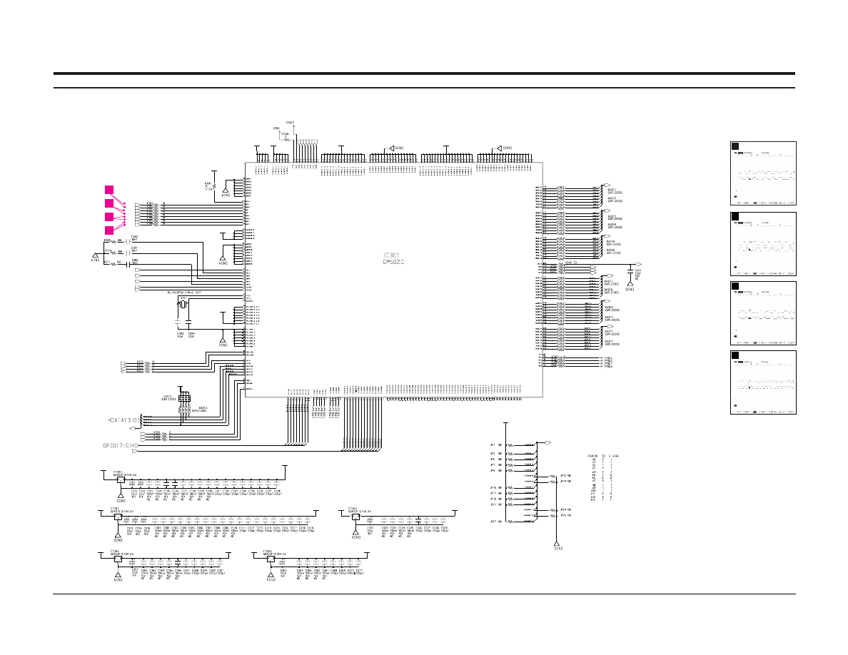
9 Schematic Diagrams
9-1 Scaler Part Schematic Diagram
+3.3V_P
PVDD_3.3
AVDD_2.5
+3.3V_A
DVDD_3.3
DVDD_3.3
+3.3V_D
DVDD_3.3
DVDD_2.5
AVDD_3.3
AVDD_3.3
DVDD_3.3
AVDD_2.5
AVDD_3.3
DVDD_3.3
PVDD_3.3
+2.5V_D
+2.5V_A
DVDD_2.5
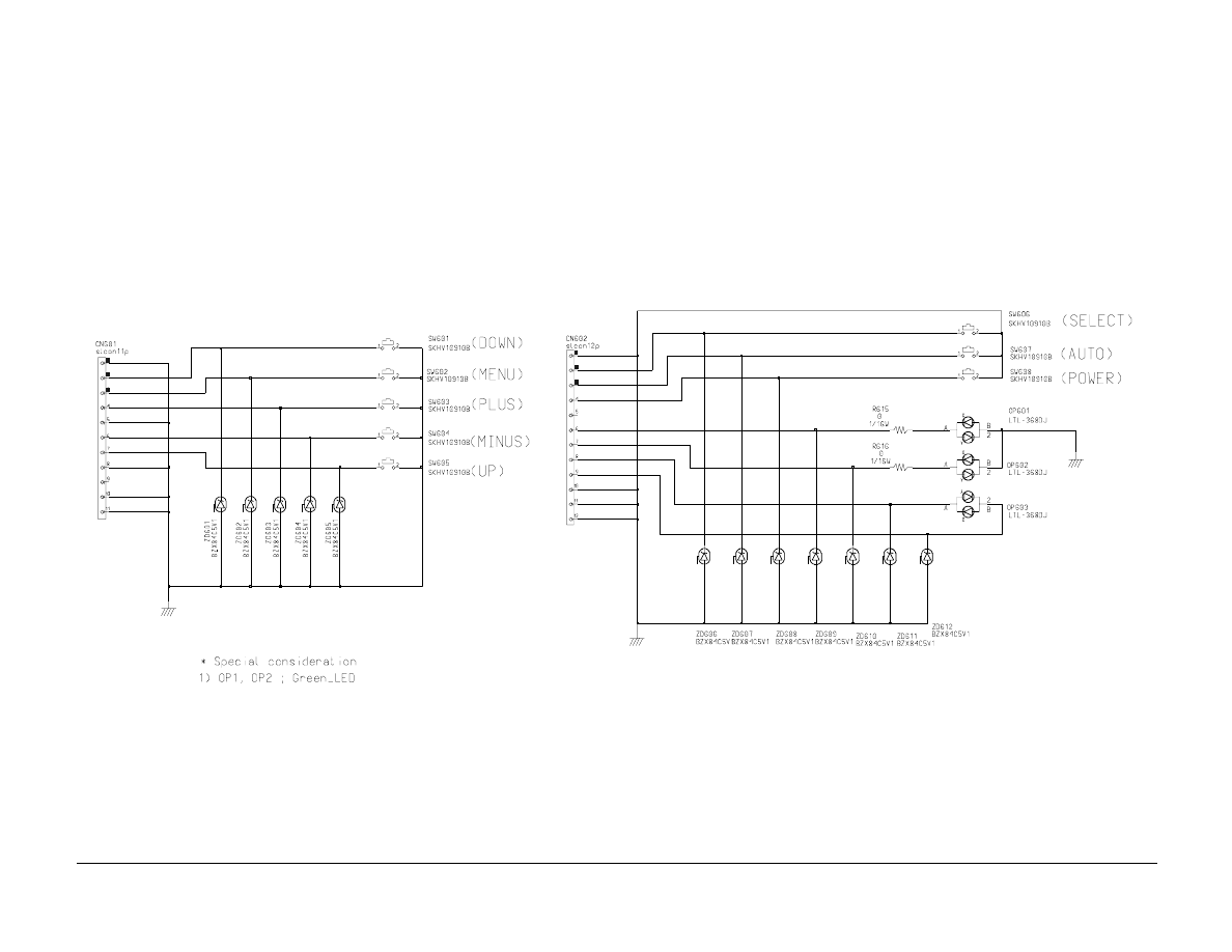
MENU_KEY
A
U
T
O_KEY
SEL_KEY
MINUS_KEY
PLUS_KEY
DO
WN_KEY
UP_KEY
DCLK
DAR(7:0)
DAG(7:0)
DAB(7:0)
FSADDR(13:0)
FSADDR(13:0)
DEN
DVS
DHS
DBG(7:0)
DBB(7:0)
HFS
*IRQ
*IRQIN
*RESET
DDDC_SCL
DDDC_SDA
Rx2+
Rx2-
Rx1+
Rx1-
Rx0+
Rx0-
RxC+
RxC-
DBR(7:0)
BLU+
GRN+
RED+
A_H*V_SYNC
A_V_SYNC
HCLK
12
13
14
15
12
R301, R302
13
R303, R304
14
R305, R306
15
R307, R308
9 Schematic Diagrams
9-2
1503FP
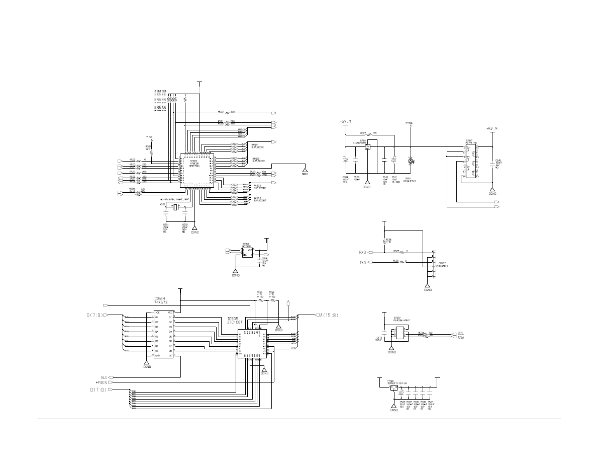
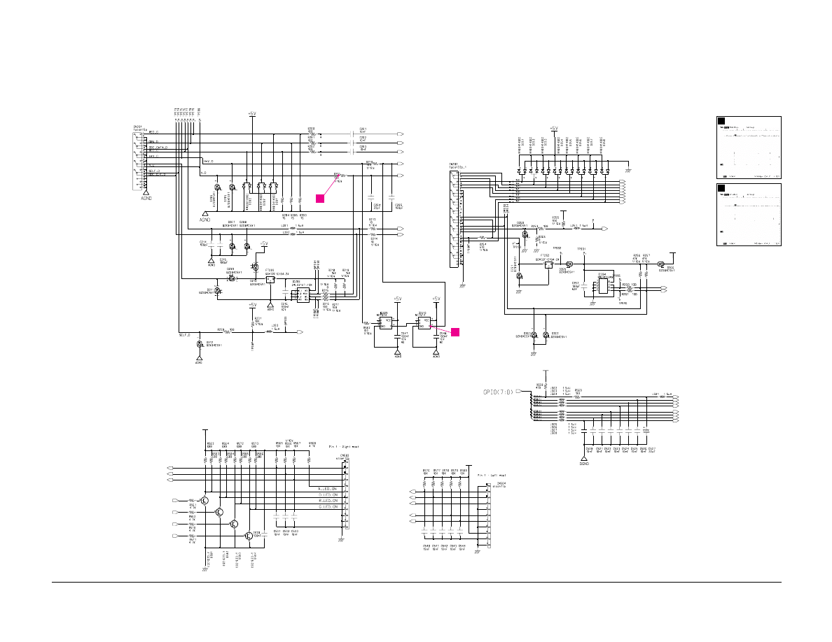
9-2 MCU Part Schematic Diagram
+5V
+5V_M
+5V_M
+5V_M
+5V_M
+5V_M
+5V_M
A(15)
*RESET
D(7:0)
HCLK
RESET
A(15)
A(16)
BANK
A(16)
A(15:8)
*PSEN
ALE
HFS
*IRQ
BANK
HDATA(3:0)
RESET
RXD
TXD
PWR_SW
SDA
SCL
CHK_DSUB
CHK_DVI
9 Schematic Diagrams
1503FP
9-3
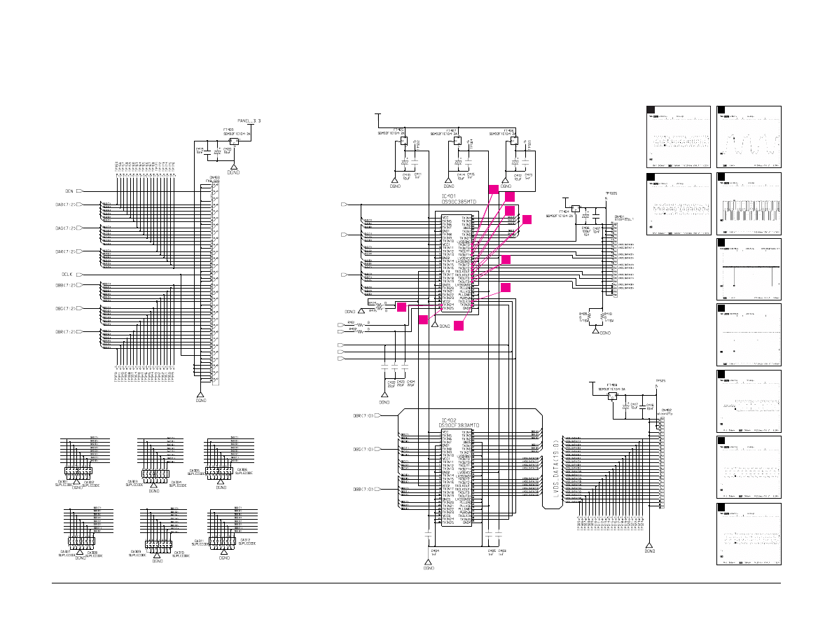
9-3 LCD Output Part Schematic Diagram
LVDS_3.3
PANEL_3.3
PANEL_3.3
LVDS_EN
DEN
DCLK
DAB(7:0)
DVS
DHS
DAR(7:0)
DAG(7:0)
4
3
2
1
5
6
7
8
9
8
IC401 #45, 46
7
IC401 #41, 42
6
IC401 #39, 40
5
IC401 #37, 38
4
IC401 #27
9
IC401 #47, 48
3
IC401 #28
2
IC401 #30
1
IC401 #31
9 Schematic Diagrams
9-4
1503FP
9-4 Video Input Part Schematic Diagram
Power Function
Menu Function
+5V
+5V
+5V
+5V
+5V
BRIGHT
Rx1+
A_H*V_SYNC
CHK_DSUB
DDDC_SCL
DDDC_SDA
LED_GRN
A_V_SYNC
PWR_SW
AUTO_KEY
SEL_KEY
LVDS_EN
PANEL_EN
D_LED
A_LED
LED_RED
LED_GRN
BKLT_EN
Rx0-
A_LED
D_LED
DOWN_KEY
MENU_KEY
PLUS_KEY
UP_KEY
MINUS_KEY
LED_RED
GRN+
RED+
ADDC_DATA
ADDC_CLK
BLU+
CHK_DVI
Rx2+
Rx1-
Rx2-
RxC-
RxC+
Rx0+
11
10
10
IC510 #4
11
R211
9 Schematic Diagrams
1503FP
9-5
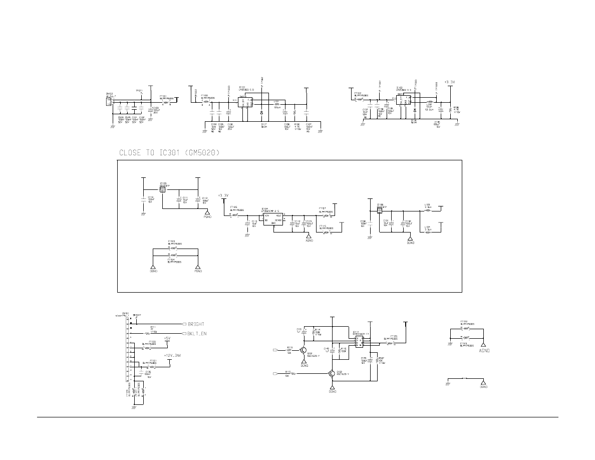
9-5 Power Part Schematic Diagram
+12V
LVDS_3.3
+3.3V
PANEL_3.3
+12V
+3.3V_A
+3.3V_D
+5V
+2.5V_A
+2.5V_D
+12V_INV
+5V
+3.3V_P
+5V
+12V
PANEL_EN
LVDS_EN
9 Schematic Diagrams
9-6
1503FP
9-6 Function Part Schematic Diagram

Samsung Electronics Co., Ltd. November 2000
Printed in Korea
P/N :BN68-00175B-01
Wyszukiwarka
Podobne podstrony:
Service Manual Sony TFT LCD Color Monitor CPD L133 Schematic
Proview RA783 LCD Service Manual
Proview PZ456 LCD Service Manual
Proview SH770I LCD Service Manual
Proview RA583 LCD Service Manual (Xerox)
BMW E38 E39 Wide Screen Monitor Service Manual
Proview SH970I LCD Service Manual
Proview SH770 LCD Service Manual
Proview AY965 LCD Service Manual
Proview RA783 LCD Service Manual
Proview PZ456 LCD Service Manual
Proview SH770I LCD Service Manual
więcej podobnych podstron