M
The Building Regulations 2000
Access to and use of buildings
APPROVED DOCUMENT
Coming into effect 1 May 2004
M1
Access and use
M2
Access to extensions to buildings other than
dwellings
M3
Sanitary conveniences in extensions to
buildings other than dwellings
M4
Sanitary conveniences in dwellings
2004 EDITION
9 780117 539013
I S B N 0 - 1 1 - 7 5 3 9 0 1 - 5
Building Regulations 2000
APPROVED
DOCUMENT
M
Access to and
use of buildings
© Crown copyright 2003. Copyright in the typographical arrangements rests
with the Crown. Published for the Office of the Deputy Prime Minister under
licence from the Controller of Her Majesty’s Stationery Office.
This publication, excluding logos, may be reproduced free of charge in any
format or medium for research, private study or for internal circulation within
an organisation. This is subject to it being reproduced accurately and not used
in a misleading context. The material must be acknowledged as Crown
copyright and the title of the publication specified.
For any other use of this material, please write to The HMSO Licensing
Division, HMSO, St Clements House, 2–16 Colegate, Norwich NR3 1BQ.
Fax: 01603 72300 or e-mail: licensing@cabinet-office.x.gsi.gov.uk
www.tso.co.uk
Published by TSO (The Stationery Office) and available from:
Online
www.tso.co.uk/bookshop
Mail,Telephone, Fax & E-mail
TSO
PO Box 29, Norwich NR3 1GN
Telephone orders/General enquiries: 0870 600 5522
Fax orders: 0870 600 5533
E-mail: book.orders@tso.co.uk
Textphone: 0870 240 3701
TSO Shops
123 Kingsway, London WC2B 6PQ
020 7242 6393 Fax 020 7242 6394
68–69 Bull Street, Birmingham B4 6AD
0121 236 9696 Fax 0121 236 9699
9–21 Princess Street, Manchester M60 8AS
0161 834 7201 Fax 0161 833 0634
16 Arthur Street, Belfast BT1 4GD
028 9023 8451 Fax 028 9023 5401
18–19, High Street, Cardiff CF10 1PT
029 2039 5548 Fax 029 2038 4347
71 Lothian Road, Edinburgh EH3 9AZ
0870 606 5566 Fax 0870 606 5588
TSO Accredited Agents
(see Yellow Pages)
and through good booksellers
£12
Following the reorganisation of the government in May 2002, the responsibilities of
the former Department of the Environment, Transport and the Regions (DETR) and
latterly Department for Transport, Local Government and the Regions (DTLR) in this
area were transferred to the Office of the Deputy Prime Minister
30564 Doc M cover 2k4 23/10/03 16:24pm Page 1

The following documents have been
approved and issued by the Secretary
of State for the purpose of providing
practical guidance with respect to the
requirements of the Building
Regulations 2000 (as amended)
Approved Document A - Structure:
1992 Edition, fourth impression (with
amendments) 1994, further amended
2000
Approved Document B - Fire safety:
2000 Edition, amended 2000 and 2002
Approved Document C - Site
preparation and resistance to
moisture: 1992 Edition, second
impression (with amendments) 1992,
further amended 2000
Approved Document D - Toxic
substances: 1985 Edition, amended
1992, further amended 2000
Approved Document E - Resistance
to the passage of sound: 2003 Edition
Approved Document F - Ventilation:
1995 Edition, amended 2000
Approved Document G - Hygiene:
1992 Edition, second impression (with
amendments) 1992, further amended
2000
Approved Document H - Drainage
and waste disposal: 2002 Edition
Approved Document J - Combustion
appliances and fuel storage systems:
2002 Edition
Approved Document K - Protection
from falling, collision and impact:
1998 Edition, amended 2000
Approved Document L1 -
Conservation of fuel and power in
dwellings: 2002 Edition
Approved Document L2 -
Conservation of fuel and power in
buildings other than dwellings: 2002
Edition
Approved Document M - Access to
and use of buildings: 2004 Edition
Approved Document N - Glazing -
safety in relation to impact, opening
and cleaning: 1998 Edition, amended
2000
Approved Document to support
regulation 7 - materials and
workmanship: 1999 Edition, amended
2000
Approved Documents
Access to and use of buildings
Approved Document M
81
M
APPROVED DOCUMENTS
MAIN CHANGES IN THE 2004
EDITION
This edition of the Approved Document
M ‘Access to and use of buildings’
replaces the 1999 edition entitled
‘Access and facilities for disabled
people’. The main changes are:
a. Part M now applies generally to
material alterations of and extensions
to existing non-domestic buildings. It
applies to material changes of use to
some non-domestic uses. There is no
exception for historic buildings, but this
new edition of AD M contains guidance
on such buildings. The guidance on
dwellings in Sections 6 to 10 remains
unchanged from the 1999 edition of AD
M, with the exception that some
diagram numbers and their text
references have been changed to
permit consistency with the amended
Sections 1 to 5. Some publication
references, particularly those
concerning lifts and sports facilities,
have been replaced to reflect the most
recent guidance available.
b. The guidance draws on the
recommendations of British Standard
BS 8300:2001 ‘Design of buildings and
their approaches to meet the needs of
disabled people - Code of Practice’.
There are some instances where the
guidance in this Approved Document
differs from the recommendations in
the edition of BS 8300 current at the
date of publication of the AD. It is the
intention of the British Standards
Institution to review such anomalies as
may exist and where practicable to
take them into account in future
editions of the standard.
c. The requirements in the new Part M
no longer refer to ‘disabled people’.
The aim of the new Part M and AD M is
to foster a more inclusive approach to
design to accommodate the needs of
all people. A new section in the AD
(Section 4) on ‘Facilities in buildings
other than dwellings’ has been
introduced to cover audience and
spectator facilities, refreshment
facilities, sleeping accommodation and
switches, outlets and controls. The
guidance on changing facilities has
been relocated to Section 5 ‘Sanitary
accommodation in buildings other than
dwellings’. This new edition of AD M
includes guidance in Section 0 ‘General
Guidance’ on educational
establishments and clarifies the
treatment of purpose-built student
accommodation.
d. The explanation of the relationship
between Part M and the Disability
Discrimination Act 1995 has been
amended in ‘Use of Guidance’ to
reflect Regulations made or revoked
since the 1999 edition of AD M was
published.
e. The concept of the Access
Statement has been introduced for the
first time. It is recommended that an
Access Statement is provided to
identify the philosophy and approach to
inclusive design adopted, particularly
when the approach taken to satisfying
the Requirements differs from that
represented by the guidance in the
Approved Document.
Approved Document M
Access to and use of buildings
Printed in the United Kingdom for The Stationery Office
152625
C200
11/03
30564 Doc M cover 2k4 23/10/03 16:24pm Page 3

PAGE
USE OF GUIDANCE
5
THE REQUIREMENTS
9
SECTION 0: GENERAL GUIDANCE
Performance
12
Where the requirements apply
Application of Part M
12
Extensions and material
alterations: dwellings
12
Extensions of non-domestic
buildings
13
Material alterations of non-
domestic buildings
13
Material changes of use
14
Car parking and setting down
14
What requirements apply
14
(i)
Buildings other than
dwellings
14
(ii)
Dwellings
15
Educational establishments
15
Historic buildings
15
Access Statements
16
Definitions
17
SECTIONS 1-5: BUILDINGS OTHER
THAN DWELLINGS
Section 1: Access to buildings other
than dwellings
Objectives
19
Level approach from the boundary
of the site and car parking
19
On-site car parking and setting
down
20
Ramped access
22
Stepped access
23
Handrails to external stepped and
ramped access
25
Hazards on access routes
26
PAGE
Section 2: Access into buildings
other than dwellings
Objectives
28
Accessible entrances
28
Doors to accessible entrances
28
Manually operated non-powered
entrance doors
30
Powered entrance doors
30
Glass entrance doors and glazed
screens
31
Entrance lobbies
31
Section 3: Horizontal and vertical
circulation in buildings other than
dwellings
Objective
34
Entrance hall and reception area
34
Internal doors
34
Corridors and passageways
36
Internal lobbies
37
Vertical circulation within the
building
37
Provision of lifting devices
37
General requirements for lifting
devices
38
Passenger lifts
38
Lifting platforms
40
Wheelchair platform stairlifts
41
Internal stairs
42
Internal ramps
42
Handrails to internal steps, stairs
and ramps
43
Section 4: Facilities in buildings
other than dwellings
Objectives
44
Audience and spectator facilities
44
Refreshment facilities
46
Sleeping accommodation
46
Switches, outlets and controls
50
Aids to communication
51
Contents
1
M
Access to and use of buildings
Approved Document M

PAGE
Section 5: Sanitary accommodation
in buildings other than dwellings
Objectives
52
Sanitary accommodation generally
52
Provision of toilet accommodation
53
Wheelchair-accessible unisex toilets 53
Toilets in separate-sex washrooms
55
Wheelchair-accessible changing and
shower facilities
58
Wheelchair-accessible bathrooms
60
SECTIONS 6-10: DWELLINGS
Section 6: Means of access to and
into the dwelling
Objective
64
Approach to the dwelling
64
Level approach
65
Ramped approach
65
Stepped approach
65
Approach using a driveway
65
Access into the dwelling
65
Entrance doors
66
Section 7: Circulation within the
entrance storey of the dwelling
Objective
67
Corridors, passageways and internal
doors within the entrance storey
67
Vertical circulation within the
entrance storey
68
Section 8: Accessible switches and
socket outlets in the dwelling
Objective
68
Section 9: Passenger lifts and
common stairs in blocks of flats
Objectives
69
Common stairs
69
Lifts
70
Section 10: WC provision in the
entrance storey of the dwelling
Objectives
71
PAGE
Index
72
Standards referred to
77
Other publications referred to
78
Other sources of information
79
Approved Document M
Access to and use of buildings
2
M

DIAGRAMS
PAGE
1.
Tactile paving and an example
of its use at an uncontrolled
crossing
20
2.
Parking bay designated for
disabled people
21
3.
Relationship of ramp gradient
to the going of a flight
22
4.
Stepped access – key
dimensions and use of
hazard warning surface
24
5.
External steps and stairs –
key dimensions
25
6.
Examples of acceptable step
profiles and key dimensions
for external stairs
25
7. Handrail
design
26
8.
Avoiding hazards on access
routes
27
9.
Effective clear width and
visibility requirements of doors 30
10. Key dimensions for lobbies
with single leaf doors
33
11. Key dimensions associated
with passenger lifts
39
12. Internal stairs – key
dimensions
42
13. An example of wheelchair
spaces in a lecture theatre
45
14. Possible location of wheelchair
spaces in front of a rear aisle
47
15. An example of wheelchair
space provision in a cinema
or theatre
47
16. An example of a shared
refreshment facility
48
PAGE
17. One example of a wheelchair-
accessible hotel bedroom
with en-suite sanitary facilities 49
18. Unisex
wheelchair-accessible
toilet with corner WC
55
19. Heights and arrangement of
fittings in a unisex wheelchair-
accessible toilet
56
20. Heights of various fittings in
toilet accommodation
56
21. WC cubicle for ambulant
disabled people
57
22. An example of a self-contained
changing room for individual
use
59
23. An example of a self-contained
shower room for individual
use
60
24. An example of a shower room
with corner WC for individual
use
61
25. An example of a bathroom
incorporating a corner WC
62
26. Grab rails and fittings
associated with a bath
63
27. External step profiles
65
28. Corridors, passages and
internal doors
67
29. Heights of switches, socket
outlets etc
68
30. Common stairs in blocks of
flats
69
31. Clear space for frontal
access to WC
71
32. Clear space for oblique
access to WC
71
Approved Document M
3
M

Approved Document M
Access to and use of buildings
4
M

THE APPROVED DOCUMENTS
This document is one of a series that
has been approved and issued by the
Secretary of State for the purpose of
providing practical guidance with
respect to the requirements of
Schedule 1 to and regulation 7 of the
Building Regulations 2000 for England
and Wales (SI 2000/2531). SI
2000/2531 has been amended by the
Building (Amendment) Regulations
2001 (SI 2001/3335), the Building
(Amendment) Regulations 2002 (SI
2002/440), the Building (Amendment)
(No. 2) Regulations 2002 (SI 2002/2871)
and the Building (Amendment)
Regulations 2003 (SI 2003/[to be
inserted]).
At the back of this document is a list
of all the documents that have been
approved and issued by the
Secretary of State for this purpose.
Approved Documents are intended to
provide guidance for some of the more
common building situations. However,
there may well be alternative ways of
achieving compliance with the
requirements. Thus there is no
obligation to adopt any particular
solution contained in an Approved
Document if you prefer to meet the
relevant requirement in some other
way.
Other requirements
The guidance contained in an Approved
Document relates only to the particular
requirements of the Regulations which
the document addresses. The building
work will also have to comply with the
requirements of any other relevant
paragraphs in Schedule 1 to the
Regulations.
There are Approved Documents which
give guidance on each of the Parts of
Schedule 1 and on regulation 7.
LIMITATION ON REQUIREMENTS
In accordance with regulation 8, the
requirements in Parts A to D, F to K
and N (except for paragraphs H2 and
J6) of Schedule 1 to the Building
Regulations do not require anything to
be done except for the purpose of
securing reasonable standards of
health and safety for persons in or
about buildings (and any others who
may be affected by buildings or
matters connected with buildings). This
is one of the categories of purpose for
which building regulations may be
made.
Paragraphs H2 and J6 are excluded
from regulation 8 because they deal
directly with prevention of the
contamination of water. Parts E and M
(which deal, respectively, with
resistance to the passage of sound,
and access to and use of buildings) are
excluded from regulation 8 because
they address the welfare and
convenience of building users. Part L is
excluded from regulation 8 because it
addresses the conservation of fuel and
power. All these matters are amongst
the purposes, other than health and
safety, that may be addressed by
Building Regulations.
MATERIALS AND WORKMANSHIP
Any building work which is subject to
the requirements imposed by Schedule
1 to the Building Regulations should, in
accordance with regulation 7, be
carried out with proper materials and in
a workmanlike manner.
You may show that you have complied
with regulation 7 in a number of ways.
These include the appropriate use of a
product bearing CE marking in
accordance with the Construction
Products Directive (89/106/EEC)
1
as
amended by the CE marking Directive
(93/68/EEC)
2
, or a product complying
with an appropriate technical
specification (as defined in those
Directives), a British Standard, or an
alternative national technical
specification of any state which is a
Approved Document M
5
M
Use of Guidance
Access to and use of buildings
THE BUILDING REGULATIONS 2000
1
As implemented by the Construction Products
Regulations 1991 (SI 1991/1620)
2
As implemented by the Construction Products
(Amendment) Regulations 1994 (SI 1994/3051)

contracting party to the European
Economic Area which, in use, is
equivalent, or a product covered by a
national or European certificate issued
by a European Technical Approval
issuing body, and the conditions of use
are in accordance with the terms of the
certificate. You will find further
guidance in the Approved Document
supporting regulation 7 on materials
and workmanship.
Independent certification schemes
There are many UK product
certification schemes. Such schemes
certify compliance with the
requirements of a recognised document
which is appropriate to the purpose for
which the material is to be used.
Materials which are not so certified
may still conform to a relevant
standard.
Many certification bodies which
approve such schemes are accredited
by UKAS.
Technical specifications
Under section 1(1)(a) of the Building
Act 1984, Building Regulations may be
made for various purposes including
health, safety, welfare, convenience,
conservation of fuel and power and
prevention of contamination of water.
Standards and technical approvals are
relevant guidance to the extent that
they relate to these considerations.
However, they may also address other
aspects of performance such as
serviceability, or aspects, which
although they relate to the purposes
listed above are not covered by the
current Regulations.
When an Approved Document makes
reference to a named standard, the
relevant version of the standard is the
one listed at the end of the publication.
However, if this version has been
revised or updated by the issuing
standards body, the new version may
be used as a source of guidance
provided it continues to address the
relevant requirements of the
Regulations.
The appropriate use of a product which
complies with a European Technical
Approval as defined in the Construction
Products Directive will meet the
relevant requirements.
The Office intends to issue periodic
amendments to its Approved
Documents to reflect emerging
harmonised European Standards.
Where a national standard is to be
replaced by a European harmonised
standard, there will be a co-existence
period during which either standard
may be referred to. At the end of the
co-existence period the national
standard will be withdrawn.
MIXED USE DEVELOPMENT
In mixed use developments part of a
building may be used as a dwelling
while another part has a non-domestic
use. In such cases, if the requirements
of the Regulations for dwellings and
non-domestic use differ, the
requirements for non-domestic use
should apply in any shared parts of the
building.
THE WORKPLACE (HEALTH,
SAFETY AND WELFARE)
REGULATIONS 1992
The Workplace (Health, Safety and
Welfare) Regulations 1992 as amended
by The Health and Safety
(Miscellaneous Amendments)
Regulations 2002 (SI 2002/2174)
contain some requirements which
affect building design. The main
requirements are now covered by the
Building Regulations, but for further
information see: ‘Workplace health,
safety and welfare. Workplace (Health,
Safety and Welfare) Regulations 1992,
Approved Code of Practice’ L24.
Published by HSE Books 1992 (ISBN 0
7176 0413 6).
The Workplace (Health, Safety and
Welfare) Regulations 1992 apply to the
common parts of flats and similar
buildings if people such as cleaners
and caretakers are employed to work in
these common parts. Where the
requirements of the Building
Regulations that are covered by this
Approved Document M
Access to and use of buildings
6
M
THE BUILDING REGULATIONS 2000

Part do not apply to dwellings, the
provisions may still be required in the
situations described above in order to
satisfy the Workplace Regulations.
DISABILITY DISCRIMINATION ACT
1995 AND THE DISABILITY
DISCRIMINATION (EMPLOYMENT)
REGULATIONS 1996
The Disability Discrimination Act 1995
(“DDA”) contains duties to make
reasonable adjustments to physical
features of premises in certain
circumstances.
Following the guidance in this
Approved Document (or a previous
version thereof) is not a requirement for
satisfying these duties to make
reasonable adjustments. However, the
following points should be noted.
Duties in the Employment Field
Up to 30 September 2004: a duty to
make reasonable adjustments is set out
in section 6 of the DDA and applies to
employers with 15 or more employees.
However, an exemption from this duty
is provided by regulation 8 of the
Disability Discrimination (Employment)
Regulations 1996 (SI 1996/1456) (“the
1996 Regulations”): an employer is not
required to alter any physical
characteristic of a building, which was
adopted with a view to satisfying the
requirements of Part M of the Building
Regulations and met those
requirements at the time the building
works were carried out and continues
substantially to meet those
requirements.
From 1 October 2004: the exemption in
the 1996 Regulations ceases to apply.
Some changes to the duty to make
reasonable adjustments are introduced
from 1 October 2004 and its coverage
is extended to all employers
(irrespective of size) and a range of
other bodies and occupations (eg
qualifications bodies and partners in
business partnerships). Depending on
the nature of the organisation
concerned, the revised duty of
reasonable adjustment is set out in
sections 4A, 4B(5), 4B(6), 4E, 6B, 7B,
7D, 14, 14B, 14D and 16A(5) of the
DDA as amended by the Disability
Discrimination Act 1995 (Amendment)
Regulations 2003 (SI 2003/1673).
Duties of providers of services to the
public
Up to 30 September 2004: there is no
duty on service providers to make
reasonable adjustments to physical
features of premises.
From 1 October 2004: The duty to
make reasonable adjustments set out
in sections 21(2)(a), (b) and (c) of the
DDA comes into force. It applies to all
those who provide services to the
public irrespective of their size. It
requires service providers to take
reasonable steps to remove, alter or
provide a reasonable means of
avoiding a physical feature of their
premises, which makes it unreasonably
difficult or impossible for disabled
people to make use of their services.
An exemption from these duties is
provided by regulation 3 of the
Disability Discrimination (Providers of
Services)(Adjustment of Premises)
Regulations 2001 (SI 2001/3253) (“2001
Regulations”) - with further detail of
the exemption set out in the Schedule
to the 2001 Regulations. The 2001
Regulations provide that, if a physical
feature accords with the relevant
objectives, design considerations and
provisions in the 1992 or 1999 editions
of Approved Document M, the service
provider will not have to make
adjustments to that feature if 10 years
or less have passed since it was
constructed or installed. For building
works where the Building Regulations
applied, the effective edition will be the
version which applied in meeting those
Building Regulations.
The 2001 Regulations specify that the
exemption only applies to physical
features constructed or installed in
accordance with the 1992 or 1999
editions of Approved Document M.
They do not provide for the exemption
to apply to features constructed or
installed in accordance with
subsequent editions of the Approved
Document. The Government is
Access to and use of buildings
Approved Document M
7
M
THE BUILDING REGULATIONS 2000

considering whether the exemption
should be extended to features
constructed or installed in accordance
with this 2004 edition of the Approved
Document and will make an
announcement if it decides the
exemption should be so extended.
Approved Document M
8
M
THE BUILDING REGULATIONS 2000

This Approved Document, which takes
effect on 1 May 2004, deals with the
requirements of Part M of Schedule 1
to the Building Regulations 2000 (as
amended by SI 2003/2692).
The Requirements
Access to and use of buildings
Approved Document M
9
M
ACCESS TO AND USE OF BUILDINGS
PART M ACCESS TO AND USE OF BUILDINGS
Access and Use
M1.
Reasonable provision shall be made for people to—
(a)
gain access to; and
(b) use
the building and its facilities.
Access to Extensions to Buildings other than Dwellings
M2.
Suitable independent access shall be provided to the extension
where reasonably practicable.
Sanitary Conveniences in Extensions to Buildings other than
Dwellings
M3.
If sanitary conveniences are provided in any building that is to be
extended, reasonable provision shall be made within the extension for
sanitary conveniences.
Sanitary Conveniences in Dwellings
M4.
(1)
Reasonable provision shall be made in the entrance storey
for sanitary conveniences, or where the entrance storey contains no
habitable rooms, reasonable provision for sanitary conveniences shall be
made in either the entrance storey or principal storey.
(2)
In this paragraph “entrance storey” means the storey
which contains the principal entrance and “principal storey” means the
storey nearest to the entrance storey which contains a habitable room, or
if there are two such storeys equally near, either such storey.
Requirement
Limits on application
The requirements of this Part do not apply to –
(a) an extension of or material alteration of a
dwelling; or
(b) any part of a building which is used solely
to enable the building or any service or fitting
in the building to be inspected, repaired or
maintained.
Requirement M2 does not apply where suitable
access to the extension is provided through the
building that is extended.
Requirement M3 does not apply where there is
reasonable provision for sanitary conveniences
elsewhere in the building, such that people
occupied in, or otherwise having occasion to
enter the extension, can gain access to and use
those sanitary conveniences.
Notes
Means of escape in case of fire: the
scope of Part M and AD M is limited to
matters of access to, into, and use of,
a building. It does not extend to means
of escape in the event of fire, for which
reference should be made to Approved
Document B – ‘Fire Safety’.
Stairs and ramps: Approved Document
K – ‘Protection from falling, collision
and impact’ contains general guidance
on stair and ramp design. The guidance
in AD M reflects more recent ergonomic
research conducted to support BS
8300 (see below) and should take
precedence over guidance in AD K
where it may appear to conflict. Further
research on stairs is currently being
conducted and will be reflected in
future revisions of Part K and AD K.
Manifestation on glazed doors and
glazed screens: Approved Document
N - ‘Glazing - safety in relation to
impact, opening and cleaning’,
contains guidance on manifestation.
The guidance in AD M reflects more
recent experience of manifestation and
should take precedence over the
guidance in AD N where it may appear
to conflict, until Part N and AD N are
revised.

BS 8300:2001 ‘Design of buildings
and their approaches to meet the
needs of disabled people – Code of
Practice’: this supersedes BS
5619:1978 and BS 5810:1979. BS 8300
provides guidance on good practice in
the design of domestic and non-
domestic buildings and their
approaches so that they are convenient
to use by disabled people. The design
recommendations are based on user
trials and validated desk studies which
formed part of a research project
commissioned in 1997 and 2001 by
DETR. The guidance in this Approved
Document is based on and is
complementary to the BS, although the
BS contains much additional material
that is not apt for, or not considered
appropriate for, inclusion in guidance
accompanying regulation. Also, in a
few cases, the guidance in AD M
differs from the recommendation in BS
8300. Compliance with the
recommendations in the BS, therefore,
while ensuring good practice, is not
necessarily equivalent to compliance
with the guidance in AD M.
Attention is drawn to the following
extracts from The Building
Regulations 2000 (as amended by SI
2001/3335, SI 2002/440, SI 2002/2871
and SI 2003/2692).
Interpretation (regulation 2)
Regulation 2, as amended by SI
2003/2692, contains the following new
definition:
“independent access” to an extension
or part of a building means access to
that part which does not pass through
the rest of the building.
In the following texts of regulations 5
and 6, amendments introduced by SI
2003/[to be inserted] are underlined.
The meanings of the expressions
‘institution’, ‘public building’ and ‘shop’
used in regulation 5 are explained in
regulation 2.
Meaning of material change of use
(regulation 5)
For the purposes of paragraph 8 (1)(e)
of Schedule 1 to the Act and for the
purposes of these Regulations, there is
a material change of use where there is
a change in the purposes for which or
the circumstances in which a building
is used, so that after the change -
(a)
the building is used as a dwelling,
where previously it was not;
(b)
the building contains a flat, where
previously it did not;
(c)
the building is used as an hotel or
boarding house, where previously it
was not;
(d)
the building is used as an
institution, where previously it was not;
(e)
the building is used as a public
building, where previously it was not;
(f)
the building is not a building
described in Classes I to VI in
Schedule 2, where previously it was;
(g)
the building, which contains at
least one dwelling, contains a greater
or lesser number of dwellings than it
did previously;
(h)
the building contains a room for
residential purposes, where previously
it did not;
(i)
the building, which contains at
least one room for residential purposes,
contains a greater or lesser number of
such rooms than it did previously; or
(j)
the building is used as a shop,
where previously it was not.
Requirements relating to material
change of use (regulation 6)
(1)
Where there is a material change
of use of the whole of a building, such
work, if any, shall be carried out as is
necessary to ensure that the building
complies with the applicable
requirements of the following
paragraphs of Schedule 1-
(a)
in all cases,
B1
(means of warning and
escape)
B2
(internal fire spread - linings)
B3
(internal fire spread -
structure)
B4(2) (external fire spread - roofs)
Approved Document M
Access to and use of buildings
10
M
ACCESS TO AND USE OF BUILDINGS
B5
(access and facilities for the
fire service)
F1 and F2 (ventilation)
G1 (sanitary conveniences and
washing facilities)
G2 (bathrooms)
H1
(foul water drainage)
H6
(solid waste storage)
J1 to J3 (combustion appliances)
L1
(conservation of fuel and
power - dwellings)
L2
(conservation of fuel and
power - buildings other than
dwellings);
(b)
in the case of a material change
of use described in regulations 5(c), (d),
(e) or (f), A1 to A3 (structure);
(c)
in the case of a building
exceeding fifteen metres in height,
B4(1) (external fire spread - walls);
(d)
in the case of material change of
use described in regulation 5(a), C4
(resistance to weather and ground
moisture);
(e)
in the case of a material change
of use described in regulation 5(a), (b),
(c), (g), (h) or (i) E1 to E3 (resistance to
the passage of sound);
(f)
in the case of a material change
of use described in regulation 5(e),
where the public building consists of or
contains a school, E4 (acoustic
conditions in schools);
(g)
in the case of a material change
of use described in regulation 5(c), (d),
(e), or (j), M1 (access and use).
(2)
Where there is a material change
of use of part only of a building, such
work, if any, shall be carried out as is
necessary to ensure that -
(a)
that part complies in all cases
with any applicable requirements
referred to in paragraph (1)(a);
(b)
in a case to which sub-
paragraphs (b), (d), (e) or (f) of
paragraph (1) apply, that part complies
with the requirements referred to in the
relevant sub-paragraph;
(c)
in a case to which sub-paragraph
(c) of paragraph (1) applies, the whole
building complies with the requirement
referred to in that sub-paragraph; and
(d)
in a case to which sub-paragraph
(g) of paragraph (1) applies -
(i)
that part and any sanitary
conveniences provided in or in
connection with that part comply with
the requirements referred to in that
sub-paragraph; and
(ii)
the building complies with
requirement M1(a) of Schedule 1 to the
extent that reasonable provision is
made to provide either suitable
independent access to that part or
suitable access through the building to
that part.
Access to and use of buildings
Approved Document M
11
M
ACCESS TO AND USE OF BUILDINGS

GENERAL GUIDANCE
Performance
In the Secretary of State’s view the
requirements of Part M will be met by
making reasonable provision to ensure
that buildings are accessible and
usable.
People, regardless of disability, age or
gender, should be able to:
a.
gain access to buildings and to
gain access within buildings and use
their facilities, both as visitors and as
people who live or work in them;
b.
use sanitary conveniences in the
principal storey of a new dwelling.
The provisions are expected to enable
occupants with disabilities to cope
better with reducing mobility and to
‘stay put’ longer in their own homes.
The provisions are not necessarily
expected to facilitate fully independent
living for all people with disabilities.
Where the requirements apply
Application of Part M
0.1
The requirements apply if:
a.
a non-domestic building or a
dwelling is newly erected;
b.
an existing non-domestic building
is extended, or undergoes a material
alteration; or
c.
an existing building or part of an
existing building undergoes a material
change of use to a hotel or boarding
house, institution, public building or
shop.
The terms ‘institution’, ‘public building’
and ‘shop’ are explained in
regulation 2.
It should be noted that, regardless of
compliance with Building Regulations,
there will be obligations under the
Disability Discrimination Act 1995 for
service-providers and employers to
consider barriers created by physical
features in buildings.
Extensions and material alterations:
dwellings
0.2 Under regulation 4(2), where any
building is extended, or undergoes a
material alteration, the building work
must be carried out so that after it has
been completed the building complies
with the applicable requirements of
Schedule 1, or, where it did not fully
comply with any applicable
requirement, it is no more
unsatisfactory than before.
0.3
This rule applies to domestic as
well as to non-domestic buildings.
Under the Limits on Application in Part
M, Part M does not apply to an
extension of, or a material alteration of,
a dwelling. However, an extension of a
dwelling, or a material alteration of a
dwelling, must not make the building
less satisfactory in relation to Part M
than it was before.
0.4
Under regulation 3, the expression
“material alteration” is defined by
reference to a list of “relevant
requirements” in schedule 1. That list
includes Part M. This means that an
alteration of a dwelling is a material
alteration if the work would result in the
dwelling not complying with Part M
where previously it did. Alternatively, if
the dwelling did not previously comply
with Part M, the dwelling should not be
more unsatisfactory in relation to Part
M after the material alteration. It is
irrelevant whether or not the dwelling
was subject to Part M at the time of its
construction. Under the general Limits
on Application of Part M, the
requirements of that Part do not apply
to an extension of or a material
alteration of a dwelling. This means
that the extension or alteration work
itself need not comply with Part M.
However, a planned alteration to a
dwelling that has the potential to
reduce the compliance of the dwelling
as a whole with Part M must be carried
out in such a way that there is no
reduction in the extent of Part M
compliance. Similarly, an extension of a
dwelling need not itself comply with
Section 0
Approved Document M
Access to and use of buildings
12
M
ACCESS TO AND USE OF BUILDINGS

Part M, but it must not result in the
dwelling being less compliant with Part
M. The following examples illustrate
these points.
Example 1: a planned project involving
removal of a WC in the entrance storey
of a dwelling would be a material
alteration if it is the only WC in that
storey and the storey contains
habitable rooms. The WC must not be
removed or made less compliant with
Part M, unless another WC is provided
in the entrance storey that is no less
satisfactory in terms of compliance
with Part M that the old one.
Example 2: a planned extension (not
exempt under Class VII of schedule 2)
enclosing the principal entrance of a
dwelling must not make the dwelling
less satisfactory in terms of
requirement M1 than it was before. It
must be no less easy for people,
including disabled people, to gain
access to the dwelling, either via the
extension and the original entrance
point, or (subject to the guidance in
Section 6 of this AD) via a suitable
alternative entrance.
Extensions of non-domestic
buildings
0.5
An extension to a non-domestic
building should be treated in the same
manner as a new building, as regards
its own compliance with Part M. Under
the new Requirement M2 there must be
suitable independent access to the
extension where reasonably
practicable. Under the Limits on
Application, Requirement M2 does not
apply where the building that is
extended complies with Requirement
M1(a) so as to provide suitable access
through the building to the extension.
The concept of access encompasses
access from the boundary of the site
and from on-site car parking where
provided.
0.6
If the owners of a building prefer
not to provide independent access to a
planned extension, it is open to them
either to demonstrate that the existing
building and the approach to it already
comply with Requirement M1(a), so that
the Limit on Application of Requirement
M2 applies, or to modify the existing
building and/or the approach to it so
that the Limit on Application applies.
Such modification work would be a
material alteration. The extensions and
the alterations of the existing building
could be planned and carried out as a
single project.
0.7
In judging whether access
provision relying on the existing
building is sufficient for the Limit on
Application of Requirement M2 to
apply, and in judging whether it is
reasonably practicable for suitable
independent access to be provided,
practical constraints and cost
considerations will be relevant – see
also ‘Access Statements’ paragraphs
0.26 and 0.27 below.
0.8
Under new Requirement M3, if
sanitary conveniences are provided in
any building that is to be extended,
reasonable provision must be made
within the extension for sanitary
conveniences. However, under the
Limit on Application of Requirement
M3, this requirement does not apply if
there is reasonable provision for people
using the extension to gain access to
and to use sanitary conveniences in the
existing building. As in the case of
access to an extension, it is open to
building owners preferring not to make
provisions for sanitary conveniences in
a planned extension either to
demonstrate that reasonable provision
already exists in, or to modify, the
existing building so that the Limit on
Application of Requirement M3 applies.
In this case, too, the extension and the
modifications to the existing building
could be planned and carried out as a
single project.
Material alterations of non-domestic
buildings
0.9
Under regulation 4, where an
alteration of a non-domestic building is
a material alteration, the work itself
must comply, where relevant, with
Requirement M1. This means that
alterations to features relevant to the
compliance of a building with Part M,
such as entrances or arrangements for
people to get from one level to another
Access to and use of buildings
Approved Document M
13
M
ACCESS TO AND USE OF BUILDINGS

within the building, must result in
features that comply with Requirement
M1. Where new features relevant to the
compliance of a building with Part M
are provided, these must also comply
with Requirement M1. Reasonable
provision must be made for people to
gain access to and to use new or
altered sanitary conveniences. The
building as a whole, including access
to it from the site boundary and from
on-site car parking where provided,
must be no less compliant with
Requirement M1 following a material
alteration of a building. In the context
of a material alteration of a building, it
is not necessary, as regards the
Building Regulations, to upgrade
access to the building entrance from
the site boundary and from on-site car
parking where provided. However,
attention is drawn to the note in
paragraph 1 about the DDA.
Material changes of use
0.10 Under regulation 6, as amended,
where there is a material change of use
of the whole of a building to a hotel or
boarding house, an institution, a public
building or a shop, the building must
be upgraded, if necessary, so as to
comply with M1 (Access and use). The
terms “institution”, “public building”
and “shop” are explained in regulation
2. In particular, it should be noted that
“shop” includes use as a restaurant,
bar or public house.
0.11 Under regulation 6, as amended,
if an existing building undergoes a
change of use such that part is used as
a hotel or boarding house, an
institution, a public building or a shop,
such work if any shall be carried out as
is necessary to ensure that :
•
there is reasonable provision for
people to gain access to that part
from the site boundary and from
on-site car parking where
provided, either by means of an
independent access or by means
of a route to and through the
building;
•
that part itself complies with M1
(access and use); and
•
any sanitary conveniences
provided in, or in connection with,
that part comply with
Requirement M1: if users of that
part have the use of sanitary
conveniences elsewhere in the
building, there must be
reasonable provision for people to
gain access to and use that
sanitary accommodation,
upgraded if need be.
As in the case of extensions, the
Access Statement provides an
opportunity for developers to explain
how they have assessed what is
reasonable provision.
0.12 Where a material change of use
results in a building being used in part
as a hotel or boarding house,
institution, public building or shop, and
in part as a dwelling, regard should be
had to the guidance in Sections 1 to 5
of this Approved Document in relation
to the relevant non-domestic
accommodation and to the common
parts (see also MIXED USE
DEVELOPMENT under Use of
Guidance).
Car parking and setting down
0.13 Part M applies to those features,
outside the building, which are needed
to provide access to the building from
the edge of the site and from car
parking and setting down points within
the site.
What requirements apply
0.14 If Part M applies, reasonable
provision should be made in:
i)
Buildings other than dwellings
a.
so that people, regardless of
disability, age or gender, can reach the
principal entrance to the building and
other entrances described in this
Approved Document, from the site
boundary, from car parking within the
site, and from other buildings on the
same site (such as a university campus
a school or a hospital);
b.
so that elements of the building
do not constitute a hazard to users,
Approved Document M
Access to and use of buildings
14
M
ACCESS TO AND USE OF BUILDINGS

especially people with impaired sight,
but rather assist in wayfinding;
c.
so that people, regardless of
disability, age or gender, can have
access into, and within, any storey of
the building and to the building’s
facilities, subject to the usual gender-
related conventions regarding sanitary
accommodation;
d.
for suitable accommodation for
people in wheelchairs, or people with
other disabilities, in audience or
spectator seating;
e.
for aids to communication for
people with an impairment of hearing
or sight in auditoria, meeting rooms,
reception areas, ticket offices and at
information points; and
f.
for sanitary accommodation for
the users of the building.
ii) Dwellings
a.
so that people, including disabled
people, can reach the principal, or
suitable alternative, entrance to the
dwelling from the point of access;
b.
so that people, including disabled
people, can gain access into and within
the principal storey of the dwelling; and
c.
for WC provision at no higher
storey than the principal storey.
‘Principal storey’ is defined in
Requirement M4.
Educational establishments
0.15 From 1 April 2001, maintained
schools ceased to have exemption
from the Building Regulations. Certain
school-specific standards relating to
Parts K and M contained in the DfES
1997 Constructional Standards as
described in Circular DfES/0142/2001
are subsumed in this revision to AD M
(see 1.33 - Note re: (l) and (m), 1.36,
1.37 (b) and 3.51 - Note re: (c), (d) and
refuges).
0.16 Purpose-built student living
accommodation, including that in the
form of flats as defined in regulation
2(1), should be treated as hotel/motel
accommodation in respect of space
requirements and internal facilities (see
4.17 to 4.24).
Historic buildings
0.17 Historic buildings include:
a. listed
buildings,
b.
buildings situated in conservation
areas,
c.
buildings which are of
architectural and historical interest and
which are referred to as a material
consideration in a local authority’s
development plan,
d.
buildings of architectural and
historic interest within national parks,
areas of outstanding natural beauty,
and world heritage sites,
e.
vernacular buildings of traditional
form and construction.
0.18 The need to conserve the special
characteristics of such historic
buildings needs to be recognised. They
are a finite resource with cultural
importance. In such work the aim
should be to improve accessibility
where and to the extent that it is
practically possible, always provided
that the work does not prejudice the
character of the historic building, or
increase the risk of long-term
deterioration to the building fabric or
fittings. In arriving at an appropriate
balance between historic building
conservation and accessibility, it would
be appropriate to take into account the
advice of the local authority’s
conservation and access officers, and
English Heritage or CADW: Welsh
Historic Monuments, as well as the
views of local access groups, in order
to make the building as accessible as
possible.
0.19 Particular issues relating to work
in historic buildings that warrant
sympathetic treatment and where
advice from others could therefore be
beneficial include:
a.
restoring the historic character of
a building that had been subject to
previous inappropriate alteration, e.g.
replacement windows, doors and
rooflights;
Approved Document M
15
M
Access to and use of buildings
ACCESS TO AND USE OF BUILDINGS

b.
rebuilding a former historic
building (e.g. following a fire or filling in
a gap site in a terrace);
c.
the choice of appropriate
construction materials and techniques,
e.g. making provisions enabling the
fabric to “breathe” to control moisture
and potential long term decay
problems: see Information Sheet No 4
from The Society for the Protection of
Ancient Buildings (SPAB).
Access Statements
0.20 Much of the guidance in this
Approved Document is based on BS
8300:2001 ‘Design of buildings and
their approaches to meet the needs of
disabled people – Code of Practice’. It
is therefore by derivation based largely
on the ergonomic studies carried out to
support the British Standard. As such,
it may appear to be more prescriptive
than other Approved Documents in the
Building Regulations series. It must
always be borne in mind however that
the guidance contained in this AD is
designed to indicate one way in which
the Requirements may be met. There
may be other, equally satisfactory,
ways of meeting the Requirements.
Appropriate solutions to access
problems may vary depending on the
size, scale, nature and intended use of
the building. This may be particularly
true when applied to existing buildings
where constraints of structure and
context may make generic solutions
impracticable.
0.21 To assist building control bodies
in making judgements about whether
proposals make reasonable provision,
therefore, it is recommended that an
Access Statement should be provided
at the time plans are deposited, a
building notice is given or details of a
project are given to an approved
inspector, and updated to reflect
decisions reached on site. It should be
noted that guidance on access in the
planning system (‘Planning and Access
for Disabled People – A Good Practice
Guide’ published by ODPM)
recommends provision of an Access
Statement to identify the philosophy
and approach to inclusive design
adopted, the key issues of the
particular scheme, and the sources of
advice and guidance used. An
additional benefit of providing an
Access Statement is that it should set
out at the time of the application most
of the information needed by a building
control body, thus assisting the
dialogue between the applicant and
building control.
0.22 An Access Statement provided for
building control purposes should be
seen as complementary to, and as a
development of, the information
provided for planning purposes, rather
than as a separate document. It may
indeed be beneficial to maintain and
update such a document as the
building work progresses in order to
provide the end-user of the building,
who may have ongoing obligations
under the DDA, with a record of
decisions made which had an impact
on accessibility, and of the rationale for
such decisions.
0.23 At its very simplest, such a
statement might record that the
intention of the client, designer or
design team (‘the applicant’) was to
comply where appropriate with the
guidance in the AD, and to indicate in
what respects it was considered
appropriate. Where an applicant wishes
to depart from the guidance in
Approved Document M, either to
achieve a better solution using new
technologies (e.g. infrared activated
controls), to provide a more convenient
solution, or to address the constraints
of an existing building, the Statement
should set out the reasons for
departing from the guidance and the
rationale for the design approach
adopted. Examples of evidence that
might be cited to support such an
approach might include:
– application of the
recommendations in BS 8300
where these differ from the
provisions, or are not covered, in
AD M;
– results of current validated
research (published (say) in the
last 5 years);
Approved Document M
Access to and use of buildings
16
M
ACCESS TO AND USE OF BUILDINGS

– outcome of consultations with
other parties, e.g. Conservation
Officers, English Heritage or
CADW, local Access Officers etc.;
– convincing arguments that an
alternative solution will achieve
the same, a better, or a more
convenient outcome.
0.24 In the case of extensions and
material changes of use of buildings
other than dwellings, and particularly in
the case of historic buildings, such a
statement will allow an applicant to
identify the constraints imposed by the
existing structure and its immediate
environment and to propose
compensatory measures where full
access proves to be impracticable or
unreasonable. This will allow for an
explanation to be provided and
assessed in situations where a less-
than-fully accessible access route is
proposed to an extension, or to a
building or part of a building subject to
a material change of use; for example,
where a sub-leaseholder, in a multi-
occupancy building, plans to make a
material change of use of the top floor
premises into a rooftop-restaurant, but
for good reason has been unable to
obtain landlord consent to alter the
common parts.
0.25 The Statement will also permit the
applicant to identify buildings or
particular parts of buildings where it
would be either reasonable for access
to be restricted or unreasonable to
expect certain groups of people to
require access, for example where
hazardous materials are handled, or in
certain manufacturing processes, or
areas where archiving and bulk-
handling processes are carried out, any
of which might create hazards for
children, some disabled people or frail
elderly people.
0.26 If, in the case of a relevant
material change of use, it is
impracticable to make the existing
principal entrance or any other
appropriate existing entrance suitable
for use by particular groups of people,
or to provide a new entrance which is
suitable, the Access Statement should
state why it is not practicable to adjust
the existing entrance or provide a
suitable new entrance.
0.27 If, in the case of an extension, it
is not intended to provide a fully
compliant independent access, and the
Limit on Application of Requirement M3
does not apply, the Access Statement
should state why a fully compliant
independent access is not considered
reasonably practicable.
0.28 Further guidance on Access
Statements, from inception of a project
to the building in use, is expected to
be published by the Disability Rights
Commission and will be available on
the DRC web site at www.drc-gb.org.
Definitions
0.29 The following meanings apply to
terms throughout this Approved
Document.
Access, approach, entry or exit.
Accessible, with respect to buildings
or parts of buildings, means that
people, regardless of disability, age or
gender, are able to gain access.
Contrast visually, when used to
indicate the visual perception of one
element of the building, or fitting within
the building, against another means
that the difference in light reflectance
value between the two surfaces is
greater than 30 points. For further
information, reference should be made
to ‘Colour, contrast and perception -
Design guidance for internal built
environments’ - Reading University).
Dwelling means a house or a flat (“flat”
is defined in regulation 2(1)). However,
new blocks of flats built as student
accommodation are to be treated as
though they are hotel/motel
accommodation in respect of space
requirements and internal facilities (see
4.17 to 4.24).
Level, with respect to the surfaces of a
level approach, access routes and
landings associated with steps, stairs
and ramps means predominantly level,
but with a maximum gradient along the
direction of travel of 1:60.
Access to and use of buildings
Approved Document M
17
M
ACCESS TO AND USE OF BUILDINGS

Principal entrance, the entrance which
a visitor not familiar with the building
would normally expect to approach.
Suitable, with respect to means of
access and facilities, means that they
are designed for use by people
regardless of disability, age or gender,
but subject to the usual gender-related
conventions regarding sanitary
accommodation.
Usable, with respect to buildings or
parts of buildings means that they are
convenient for independent use.
0.30 The following meanings apply only
to terms used in the sections on
dwellings in this Approved Document.
Common, serving more than one
dwelling.
Habitable room, for the purpose of
defining the principal storey, means a
room used, or intended to be used, for
dwelling purposes, including a kitchen
but not a bathroom or a utility room.
Maisonette, a self-contained dwelling,
but not a dwelling-house, which
occupies more than one storey in a
building.
Point of access, the point at which a
person visiting a dwelling would
normally alight from a vehicle which
may be within or outside the plot, prior
to approaching the dwelling.
Principal entrance, the entrance which
a visitor not familiar with the dwelling
would normally expect to approach or
the common entrance to a block of
flats.
Plot gradient, the gradient measured
between the finished floor level of the
dwelling and the point of access.
Steeply sloping plot, a plot gradient of
more than 1 in 15.
Approved Document M
Access to and use of buildings
18
M
ACCESS TO AND USE OF BUILDINGS

ACCESS TO BUILDINGS OTHER
THAN DWELLINGS
Objectives
1.1
The aim is to provide a suitable
means of access for people from the
entrance point at the boundary of the
site, and from any car parking that is
provided on the site, to the building. It
is also important that routes between
buildings within a complex are also
accessible.
1.2
In designing an approach to the
building, it should be recognised that
changes in level are difficult for many
people to negotiate, including
wheelchair users, people who need to
use walking aids and people with
impaired sight. Access routes that are
too narrow can also make it difficult for
people to pass each other.
1.3
It is important to be aware that
people’s capabilities vary. For example,
for some people, a stair is easier to use
than a ramp.
1.4
The building should be designed,
within the overall constraints of space,
so that the difference in level between
the entrance storey and the site entry
point is minimised.
1.5
It is also important that potential
hazards on access routes adjacent to
buildings, e.g. open windows, are
avoided so that people, particularly
children and those with impaired sight
or hearing, are not injured.
Note: The publication ‘Inclusive
Mobility: A Guide to Best Practice on
Access to Pedestrian and Transport
Infrastructure’ gives detailed guidance
on designing the external environment.
Level approach from the boundary
of the site and car parking
Design considerations
1.6
As far as possible, access should
be level from the boundary of the site,
and from any car parking designated
for disabled people, to the principal
entrance and any entrance used
exclusively for staff or, if either of these
is not accessible, to any alternative
accessible entrances. If access is
generally required between entrances,
or between alternative accessible
entrances outside the building, this
access should as far as possible be
level. The site level of accessible
entrances should be determined
accordingly.
1.7
Where a difference in level
between the boundary of the site or car
parking designated for disabled people,
and the building, is unavoidable due to
site constraints, the approach may
have a gentle gradient over a long
distance (for all or part/s of the
approach) or it may incorporate a
number of shorter parts at a steeper
gradient, with level landings at intervals
as rest points. Generally, gradients
within the approach should be as
gentle as possible.
1.8
Where the gradient of the
approach, whether over its whole
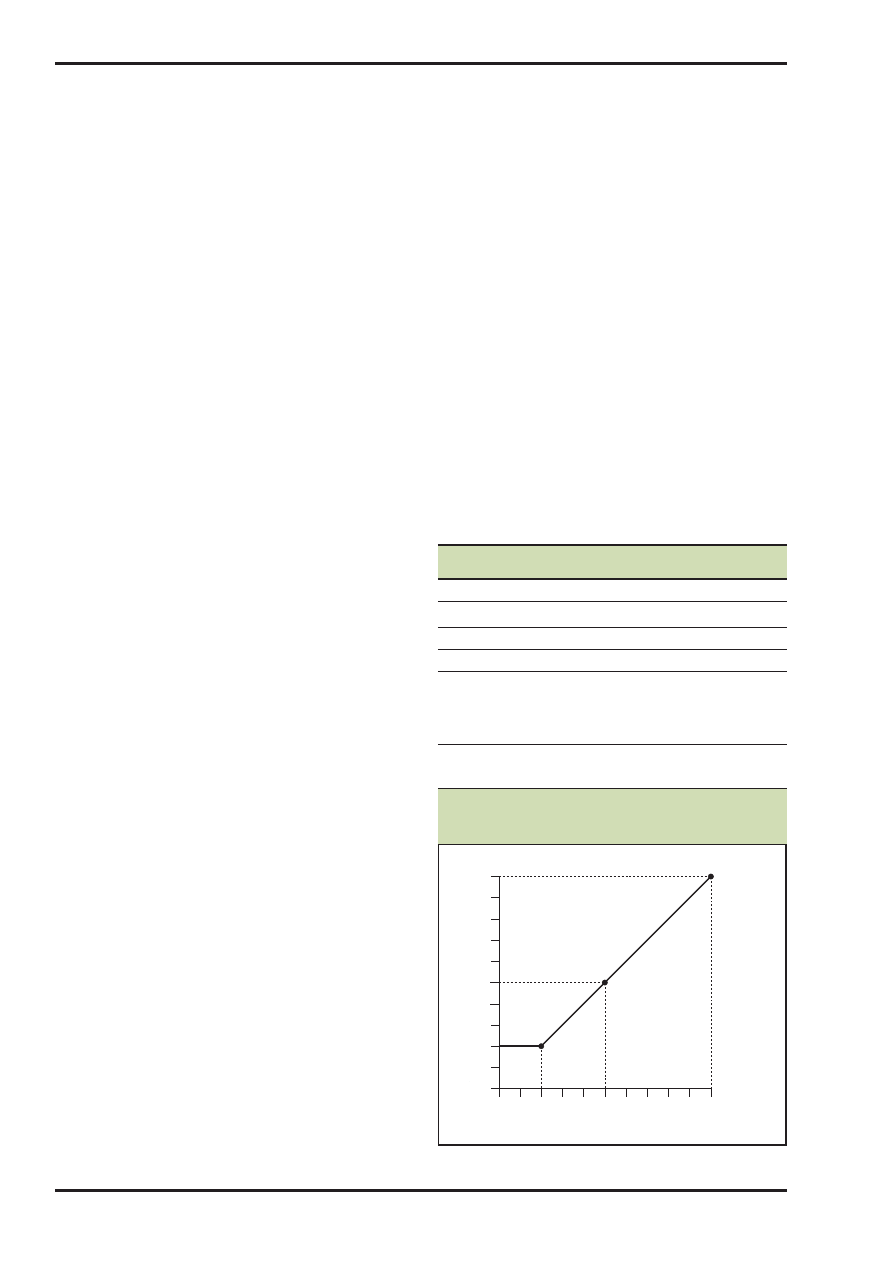
length or in part, is 1:20 or steeper,
that part of the approach should be
designed as ramped access.
1.9
All access routes to principal, or
alternative accessible, entrances
should be surfaced so that people are
able to travel along them easily, without
excessive effort and without the risk of
tripping or falling.
1.10 There should be sufficient space
for people to approach the building,
pass others who are travelling in the
opposite direction and carry out all
necessary manoeuvres.
1.11 A surface width of 1800mm can
accommodate any amount of non-
vehicular traffic without the need for
passing places. A surface width of
1200mm may be acceptable on
restricted sites, subject to a case being
made in the Access Statement.
1.12 It is important to reduce the risks
to people, particularly people with
impaired sight, when approaching and
Section 1
Access to buildings other than dwellings
Approved Document M
19
M1/M2
BUILDINGS OTHER THAN DWELLINGS
passing around the perimeter of the
building under all lighting conditions.
Provisions
1.13 A ‘level approach’ (from the
boundary of the site and from car
parking spaces designated for disabled
people to the principal entrance, to a
staff entrance or to an alternative
accessible entrance) will satisfy
Requirement M1 or M2 if:
a.
it has a surface width of at least
1.5m, with passing places, free of
obstructions to a height of 2.1m;
b.
passing places at least 1.8m wide
and at least 2m long are provided
within sight of each other (the width of
the passing place may be included in
the width of the level approach), but in
any case spaced at a distance no
greater than 50m;
c.
the gradient along its length is
either no steeper than 1:60 along its
whole length, or less steep than 1:20
with level landings (see 1.26(k))
introduced for each 500mm rise of the
access (where necessary, between
landings), in all cases with a cross-fall
gradient no steeper than 1:40;
d.
its surface is firm, durable and
slip resistant, with undulations not
exceeding 3mm under a 1m straight
edge for formless materials.
Inappropriate materials might be loose
sand or gravel;
e.
where there are different materials
along the access route, they have
similar frictional characteristics;
f.
the difference in level at joints
between paving units is no greater than
5mm, with joints filled flush or, if
recessed, no deeper than 5mm and no
wider than 10mm or, if unfilled, no
wider than 5mm;
g.
the route to the principal entrance
(or alternative accessible entrance) is
clearly identified and well lit;
h.
the danger of inadvertently
walking into a vehicular access route is
minimised by providing a separate
pedestrian route and, where there is an
uncontrolled crossing point across the
vehicular route, this is identified by a
buff coloured blister surface (see
Diagram 1, and ‘Guidance on the use
of Tactile Paving Surfaces’).
On-site car parking and setting
down
Design considerations
1.14 People who need to travel to
buildings by car need to be able to
park, have sufficient space to enter and
leave their vehicle, on occasions move
to the rear of their vehicle, then walk,
Approved Document M
Access to buildings other than dwellings
20
M1/M2
BUILDINGS OTHER THAN DWELLINGS
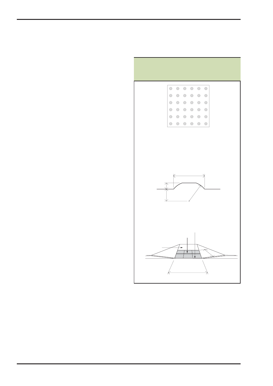
Blister surface (with 36 domes)
Dome profile
Note: Full details of tactile paving
are in "Guidance on the use of
Tactile Paving Surfaces."
16 radius
25 diameter
5
10
Gradient 1:12 max.
Blister surface
Dropped kerb flush
with carriageway
Dropped kerb at an uncontrolled crossing
800
1200 min.
Diagram 1 Tactile paving and an
example of its use at an uncontrolled
crossing
travel in a wheelchair or with
pushchairs or luggage etc. to the
principal entrance, the staff entrance,
or any alternative accessible entrance,
of the building.
1.15 The surface of a parking bay
designated for disabled people, in
particular the area surrounding the bay,
should allow the safe transfer of a
passenger or driver to a wheelchair and
transfer from the parking bay to the
access route to the building without
undue effort, barriers to wheelchairs or
hazards from tripping.
1.16 If people need to obtain tickets
for pay and display parking, the ticket
dispensing machines should be located
in a way that allows a person in a
wheelchair, or a person of short
stature, to gain access close to the
machine and reach the payment and
ticket dispensing functions.
1.17 People with mobility impairments
who arrive as passengers should be
able to alight from a vehicle close to
the principal entrance, or alternative
accessible entrance, of the building in
a way that is convenient for entry into
the building.
Note: Guidance is available in BS 8300
on:
– the provision of parking bays
designated for disabled people in
different building types;
– ticket dispensing machines;
– vehicular control barriers; and
– multi-storey car parks.
Provisions
1.18 Car parking and setting down will
satisfy Requirement M1 or M2 if:
a.
at least one parking bay
designated for disabled people is
provided on firm and level ground as
close as feasible to the principal
entrance of the building;
b.
the dimensions of the designated
parking bays are as shown in Diagram
2 (with a 1200mm accessibility zone
between, and a 1200mm safety zone
on the vehicular side of, the parking
bays, and with a dropped kerb when
there is a pedestrian route at the other
side of the parking bay);
c.
the surface of the accessibility
zone is firm, durable and slip resistant,
with undulations not exceeding 3mm
under a 1m straight edge for formless
materials. Inappropriate materials might
be loose sand or gravel;
d.
ticket machines, where necessary
for wheelchair users and people of
short stature, are adjacent to the
designated parking bays for disabled
people and have controls between
750mm and 1200mm above the ground
and a plinth which does not project in
front of the face of the machine in a
way that prevents its convenient use;
e.
a clearly sign-posted setting
down point is located on firm and level
ground as close as practicable to the
principal or alternative accessible
entrance with its surface level with the
carriageway at that point to allow
convenient access to and from the
entrance for people with walking
Approved Document M
21
Access to buildings other than dwellings
M1/M2
BUILDINGS OTHER THAN DWELLINGS
Access zone between
and at the end of
designated parking
bays
Dropped kerb where
access is to a
pedestrian route
Dimensions of parking bay
are to centre lines of markings
1400
2400
4800
1200
1200
Vehicular route
Diagram 2 Parking bay designated for
disabled people
difficulties or people using a
wheelchair.
Ramped access
Note: Where there appears to be a
conflict between the guidance in Part
M and Part K, Part M takes
precedence; see the Notes to the
Requirements.
Design considerations
1.19 If site constraints necessitate an
approach of 1 in 20 or steeper, an
approach incorporating ramped access
should be provided. Ramps are
beneficial for wheelchair users and
people pushing prams, pushchairs and
bicycles.
1.20 Gradients should be as shallow as
practicable, as steep gradients create
difficulties for some wheelchair users
who lack the strength to propel
themselves up a slope or have difficulty
in slowing down or stopping when
descending. However, there may be
circumstances, e.g. in shop fit-outs,
where a steeper gradient than the
maximum shown in Table 1 may be
necessary for a short distance. The
case for such a solution should be
made in the Access Statement.
1.21 Ramps are also not necessarily
safe and convenient for ambulant
disabled people. For example, some
people who can walk but have
restricted mobility find it more difficult
to negotiate a ramp than a stair. In
addition, adverse weather conditions
increase the risk of slipping on a ramp.
It is therefore beneficial to have steps
as well as a ramp.
1.22 Some people need to be able to
stop frequently; for instance to regain
strength or breath, or to ease pain.
1.23 Wheelchair users need adequate
space to stop on landings, to open and
pass through doors without having to
reverse into circulation routes or to
face the risk of rolling back down
slopes.
1.24 Some people have a weakness on
one side. This leads to a requirement
for support at both sides of ramps.
1.25 If the total rise of a ramped
approach is too high, it can be
unacceptably tiring for wheelchair
users and some people with walking
difficulties, even if a number of rest
landings are provided.
Note: Guidance is given in BS 8300 on:
– lighting ramped access.
Provisions
1.26 A ramped access will satisfy
Requirement M1 or M2 if:
a.
it is either readily apparent or the
approach to it is clearly sign-posted;
b.
the gradient of a ramp flight and
its going between landings are in
accordance with Table 1 and Diagram
3;
c.
no flight has a going greater than
10m, or a rise of more than 500mm;
Approved Document M
22
Table 1 Limits for ramp gradients
Going of a flight
Maximum gradient
Maximum rise
10 m
1:20
500mm
5 m
1:15
333mm
2 m
1:12
166mm
Notes:
For goings between 2m and 10m, it is acceptable to
interpolate between the maximum gradients, i.e. 1:14 for a 4m
going or 1:19 for a 9m going (see Diagram 3).
Going of ramp flight (m)
0
1:10
1:12
1:15
1:20
2 5
10
Gr
adient of r
amp
(500mm rise)
(333mm rise)
(166mm rise)
Diagram 3 Relationship of ramp
gradient to the going of a flight
Access to buildings other than dwellings
M1/M2
BUILDINGS OTHER THAN DWELLINGS

d.
there is an alternative means of
access for wheelchair users, e.g. a lift,
when the total rise is greater than 2m;
e.
it has a surface width between
walls, upstands or kerbs of at least
1.5m;
f.
the ramp surface is slip resistant,
especially when wet, and of a colour
that contrasts visually with that of the
landings;
g.
the frictional characteristics of the
ramp and landing surfaces are similar;
h.
there is a landing at the foot and
head of the ramp at least 1.2m long
and clear of any door swings or other
obstructions;
i.
any intermediate landings are at
least 1.5m long and clear of any door
swings or other obstructions;
j.
intermediate landings at least
1800mm wide and 1800mm long are
provided as passing places when it is
not possible for a wheelchair user to
see from one end of the ramp to the
other or the ramp has three flights or
more;
k.
all landings are level, subject to a
maximum gradient of 1:60 along their
length and a maximum cross fall
gradient of 1:40;
l.
there is a handrail on both sides;
m.
there is a kerb on the open side
of any ramp or landing at least 100mm
high, which contrasts visually with the
ramp or landing in addition to any
guarding required under Part K;
n.
clearly sign-posted steps are
provided, in addition, when the rise of
the ramp is greater than 300mm
(equivalent to 2 x 150mm steps).
Stepped access
Note: Where there appears to be a
conflict between the guidance in Part
M and Part K, Part M takes
precedence; see the Notes to the
Requirements.
Design considerations
1.27 People with impaired sight risk
tripping or losing their balance if there
is no warning that steps provide a
change in level. The risk is most
hazardous at the head of a flight of
steps when a person is descending.
1.28 The warning should be placed
sufficiently in advance of the hazard to
allow time to stop and not be so
narrow that it might be missed in a
single stride.
1.29 Materials for treads should not
present a slip hazard, especially when
the surface is wet.
1.30 People should be able to
appreciate easily where to place their
feet by highlighting nosings and
avoiding open rises.
1.31 People who wear callipers or who
have stiffness in hip or knee joints are
particularly at risk of tripping or
catching their feet beneath nosings.
People with a weakness on one side or
with a sight impairment need the
dimensions of the tread to be sufficient
for them to be able to place their feet
square onto it. If the going is towards
the upper end of the dimensional
range, the flight may rise to a greater
height without the need for an
intermediate landing, as the tread is
sufficiently deep to allow a person to
stand and rest at any point within the
flight. It should be noted that excessive
rounding of nosings reduces the
effective going.
1.32 Many ambulant disabled people
find it easier to negotiate a flight of
steps than a ramp and, for these
people, the presence of handrails for
support is essential.
Note: Guidance is given in BS 8300 on:
– lighting stepped access; and
– slip resistance (Annex C).
Provisions
1.33 A stepped access will satisfy
Requirement M1 or M2 if:
a.
a level landing is provided at the
top and bottom of each flight;
b.
the unobstructed length of each
landing is not less than 1200mm;
Approved Document M
23
Access to buildings other than dwellings
M1/M2
BUILDINGS OTHER THAN DWELLINGS
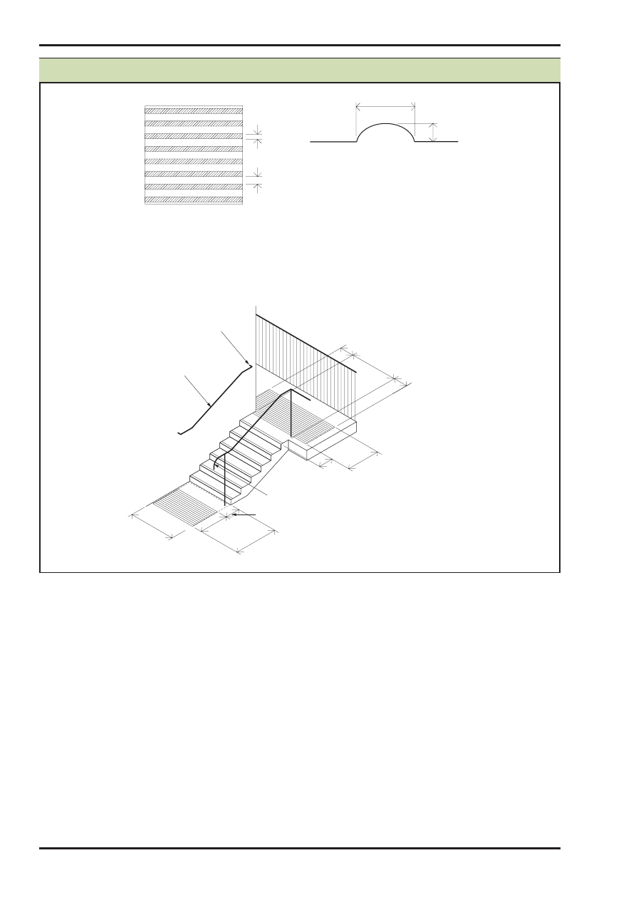
c. a
‘corduroy’
hazard
warning
surface is provided at top and bottom
landings of a series of flights to give
advance warning of a change in level in
accordance with Diagram 4;
d.
where there is side access onto
an intermediate landing, a ‘corduroy’
hazard warning surface 400mm deep is
provided either on the intermediate
landing 400mm from both upper and
lower flights, if there is sufficient space
to accommodate the surface outside
the line of the side access, or within
the side access 400mm from the
intermediate landing if there is a
continuous handrail opposite the side
access;
e.
no doors swing across landings;
f.
it has flights whose surface width
between enclosing walls, strings or
upstands is not less than 1.2m;
g.
there are no single steps;
h.
the rise of a flight between
landings contains no more than 12
risers for a going of less than 350mm
and no more than 18 risers for a going
of 350mm or greater (see Diagram 5);
i.
all nosings are made apparent by
means of a permanently contrasting
material 55mm wide on both the tread
and the riser;
Approved Document M
24
Access to buildings other than dwellings
M1/M2
BUILDINGS OTHER THAN DWELLINGS
‘Corduroy’ hazard warning surface at top of stairs
to extend at least 400 at each side of stairs
and to stop 400 from nosing
Handrail to be terminated in a way
that reduces the risk of clothing being caught
Handrail to be
continuous across
intermediate landings
400 min.
Stair width
400 min.
800 when the approach is straight on
and 400 when a conscious turn is
needed to reach the step
1200 min.
bottom landing
400
400
800
Closed end to handrail
at top and bottom
‘Corduroy’ hazard warning surface (with 8 ribs)
20
20 rib
30 gap
6
Rib profile
Note: Full details of tactile paving
are in “Guidance on the use of
Tactile Paving Surfaces.”
1200 min.
Diagram 4 Stepped access – key dimensions and use of hazard warning surface
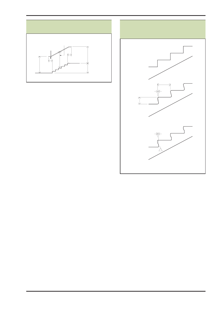
j.
the projection of a step nosing
over the tread below is avoided but, if
necessary, not more than 25mm (see
Diagram 6);
k.
the rise and going of each step is
consistent throughout a flight;
l.
the rise of each step is between
150mm and 170mm, except adjacent to
existing buildings where, due to
dimensional constraints, the case for a
different rise is argued in the Access
Statement;
m.
the going of each step is between
280mm and 425mm;
n.
rises are not open;
o.
there is a continuous handrail on
each side of a flight and landings;
p.
additional handrails divide the
flight into channels not less than 1m
wide and not more than 1.8m wide
where the overall unobstructed width is
more than 1.8m.
Note: In respect of 1.33(l) and (m), for
school buildings, the preferred
dimensions are a rise of 150mm, and a
going of 280mm.
Handrails to external stepped and
ramped access
Design considerations
1.34 People who have physical
difficulty in negotiating changes of level
need the help of a handrail that can be
gripped easily, is comfortable to touch
and, preferably, provides good forearm
support.
1.35 Handrails should be spaced away
from the wall and rigidly supported in a
way that avoids impeding finger grip.
1.36 Handrails should be set at heights
that are convenient for all users of the
building and should extend safely
beyond the top and bottom of a flight
of steps, or a ramp, to give both
stability and warning of the presence of
a change in level. Consideration should
be given to the provision of a second
handrail on stairs in a wide range of
building types, and particularly in
schools, for use by children and people
of short stature.
Provisions
1.37 Handrailing to external ramped
and stepped access will satisfy
Requirement M1 or M2 if:
Approved Document M
25
Access to buildings other than dwellings
M1/M2
BUILDINGS OTHER THAN DWELLINGS
Steps without projecting nosings are preferred
25 max.
overlap
25 max.
overlap
150 to 170
280 to 425
60° min.
Note: Rise and going dimensions apply
to all step profiles
Diagram 6 Examples of acceptable
step profiles and key dimensions for
external stairs
900 to 1000
above pitch line
300 min.
300 min.
900 to 1100
900 to 1100
12 risers max.
(going less than 350)
18 risers max.
(going 350 or more)
Diagram 5 External steps and stairs –
key dimensions
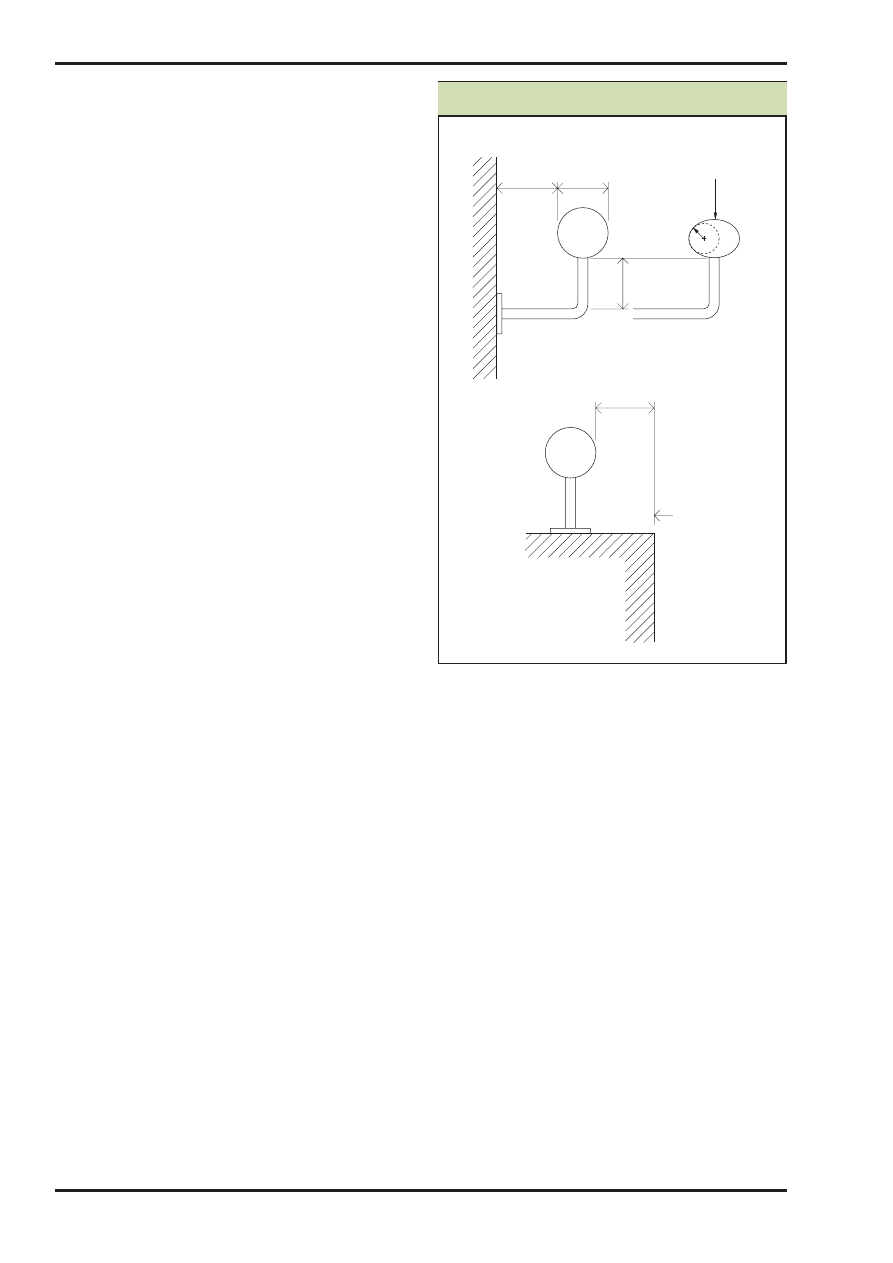
a.
the vertical height to the top of
the upper handrail from the pitch line of
the surface of a ramp, or a flight of
steps, is between 900mm and
1000mm, and from the surface of a
landing is between 900 and 1100mm
(see Diagram 5);
b.
where there is full height
structural guarding, the vertical height
to the top of a second lower handrail
from the pitch line of the surface of a
ramp, or a flight of steps, is 600mm,
where provided;
c.
it is continuous across the flights
and landings of ramped or stepped
access;
d.
it extends at least 300mm
horizontally beyond the top and bottom
of a ramped access, or the top and
bottom nosing of a flight or flights of
steps, while not projecting into an
access route;
e.
it contrasts visually with the
background against which it is seen,
without being highly reflective;
f.
its surface is slip resistant and not
cold to the touch;
g.
it terminates in a way that
reduces the risk of clothing being
caught;
h.
its profile is either circular with a
diameter of between 40 and 45mm, or
oval preferably with a width of 50mm
(see Diagram 7);
i.
it protrudes no more than 100mm
into the surface width of the ramped or
stepped access where this would
impinge on the stair width requirement
of Part B1;
j.
there is a clearance of between
60 and 75mm between the handrail and
any adjacent wall surface;
k.
there is a clearance of at least
50mm between a cranked support and
the underside of the handrail;
l.
its inner face is located no more
than 50mm beyond the surface width
of the ramped or stepped access.
Hazards on access routes
Design considerations
1.38 Features of a building that
occasionally obstruct an access route,
particularly if they are partially
transparent and therefore indistinct, or
cause a danger overhead, should not
present a hazard to building users.
Provisions
1.39 Requirement M1 or M2 will be
satisfied if:
a.
where there is a projection of
more than 100mm, during normal use,
onto an access route, windows and
doors (excluding fire escape doors) that
swing outwards towards an access
route, or other projecting features, are
protected by guarding, which
incorporates a kerb or other solid
barrier that can be detected using a
cane at ground level to direct people
Approved Document M
26
Access to buildings other than dwellings
M1/M2
BUILDINGS OTHER THAN DWELLINGS
Diagram 7 Handrail design
Non-circular handrail
preferably 50 wide
with rounded edges
60 to 75
Circular handrail
40 to 45 diameter
50 min.
15 min.
radius
p
y
with rounded edges
Ramped or
stepped
access
50 max.
min.
us
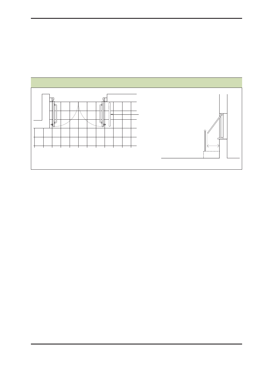
around the potential hazard (see
Diagram 8);
b.
areas below stairs or ramps where
the soffit is less than 2.1m above
ground level are protected by guarding
and low level cane detection, or a
permanent barrier giving the same
degree of protection.
Access to buildings other than dwellings
Approved Document M
27
M1/M2
BUILDINGS OTHER THAN DWELLINGS
Diagram 8 Avoiding hazards on access routes
Plan
Guarding with
cane detection
at ground level
Section
Where the projection onto an
access route is more than 100,
guarding with cane detection
at ground level
>100

ACCESS INTO BUILDINGS OTHER
THAN DWELLINGS
Objectives
2.1
The aim for all new buildings is
for the principal entrance or entrances
and any main staff entrance, and any
lobbies, to be accessible.
2.2
Where it is not possible, e.g. in an
existing building, for the principal or
main staff entrance or entrances to be
accessible, an alternative accessible
entrance should be provided.
2.3
It is important to reduce the risks
to people when entering the building.
Accessible entrances
Design considerations
2.4
Steeply sloping or restricted sites
sometimes make it impossible for the
principal or main staff entrance to be
accessible, in which case an alternative
accessible entrance may be necessary.
2.5
Accessible entrances should be
clearly sign-posted and easily
recognisable. Any structural elements,
for example supports for a canopy, are
useful in identifying the entrance, but
should not present a hazard.
2.6
The route from the exterior across
the threshold should provide weather
protection, and not present a barrier for
wheelchair users or a trip hazard for
other people. A level threshold is
preferred, especially for doors in
frequent use.
Note: Guidance on sign-posting is
given in BS 8300, ‘Inclusive Mobility’
and the ‘Sign Design Guide’.
Provisions
2.7
Accessible entrances will satisfy
Requirement M1 or M2 if:
a.
they are clearly sign-posted,
incorporating the International Symbol
of Access, from the edge of the site,
and from the principal entrance (if this
is not accessible);
b.
they are easily identified among
the other elements of the building and
the immediate environment, e.g. by
lighting and/or visual contrast;
c.
any structural supports at the
entrance do not present a hazard for
visually impaired people;
d.
there is a level landing at least
1500 x 1500mm, clear of any door
swings, immediately in front of the
entrance and of a material that does
not impede the movement of
wheelchairs;
e.
the threshold is level or, if a raised
threshold is unavoidable, it has a total
height of not more than 15mm, a
minimum number of upstands and
slopes, with any upstands higher than
5mm chamfered or rounded;
f.
any door entry systems are
accessible to deaf and hard of hearing
people, and people who cannot speak;
g.
weather protection is provided at
manual non-powered entrance doors;
h.
internal floor surfaces adjacent to
the threshold are of materials that do
not impede the movement of
wheelchairs, e.g. not coir matting, and
changes in floor materials do not create
a potential trip hazard;
i.
where mat wells are provided, the
surface of the mat is level with the
surface of the adjacent floor finish;
j.
where provided as an alternative
accessible entrance, an accessible
internal route is provided to the spaces
served by the principal or main staff
entrances.
Doors to accessible entrances
Design considerations
2.8
Doors to the principal, or
alternative accessible, entrance should
be accessible to all, particularly
wheelchair users and people with
limited physical dexterity. Entrance
doors may be manually operated
without powered assistance, or power-
operated under manual or automatic
Section 2
Approved Document M
Access into buildings other than dwellings
28
M1/M2
BUILDINGS OTHER THAN DWELLINGS

control. Entrance doors should be
capable of being held closed when not
in use.
2.9
A non-powered manually operated
entrance door, fitted with a self-closing
device capable of closing the door
against wind forces and the resistance
of draught seals, is unlikely to be
openable by many people, particularly
those who are wheelchair users or who
have limited strength.
2.10 A powered door opening and
closing system, either manually
controlled or automatically operated by
sensors, is the most satisfactory
solution for most people. An automatic
sliding door arrangement is particularly
beneficial as it avoids the risks
associated with automatic swing doors
and its use can make it possible to
reduce the length of any entrance
lobby.
2.11 Once open, all doors to
accessible entrances should be wide
enough to allow unrestricted passage
for a variety of users, including
wheelchair users, people carrying
luggage, people with assistance dogs,
and parents with pushchairs and small
children. It should be noted that double
buggies are wider than wheelchairs and
that, where relevant to the building
type, this should be borne in mind
when determining an appropriate
effective clear width for an entrance
door. There may be circumstances in
existing buildings where it is not
practicable or cost-effective to adopt
the preferred effective clear widths for
new buildings. In such cases, the
argument for adopting the minimum
dimensions for existing buildings
should be made in the Access
Statement.
2.12 People should be able to see
other people approaching from the
opposite direction, thereby allowing
sufficient reaction time for both parties
to avoid a collision. Any exceptions for
reasons of privacy or security should
be argued in the Access Statement.
Provisions
2.13 Doors to accessible entrances will
satisfy Requirement M1 or M2 if:
a.
where required to be self-closing,
a power operated door opening and
closing system is used when through
calculation and experience it appears
that it will not be possible otherwise for
a person to open the door using a
force no greater than 20N at the
leading edge;
b.
the effective clear width through a
single leaf door, or one leaf of a double
leaf door, is in accordance with Table 2,
and the rules for measurement are in
accordance with Diagram 9;
c.
unless it can be argued otherwise
in the Access Statement, e.g. for
reasons of security, door leaves, and
side panels wider than 450mm, have
vision panels towards the leading edge
of the door whose vertical dimensions
include at least the minimum zone, or
zones, of visibility between 500mm and
1500mm from the floor, if necessary
interrupted between 800mm and
1150mm above the floor, e.g. to
accommodate an intermediate
horizontal rail (see Diagram 9).
Access into buildings other than dwellings
Approved Document M
29
M1/M2
BUILDINGS OTHER THAN DWELLINGS
Table 2 Minimum effective clear widths
of doors
Direction and
New
Existing
width of approach
buildings
buildings
(mm)
(mm)
Straight-on (without a turn or
800
750
oblique approach)
At right angles to an access route
800
750
at least 1500mm wide
At right angles to an access route
825
775
at least 1200mm wide
External doors to buildings used
1000
775
by the general public
Note:
The effective clear width is the width of the opening measured
at right angles to the wall in which the door is situated from
the outside of the door stop on the door closing side to any
obstruction on the hinge side, whether this be projecting door
opening furniture, a weather board, the door, or the door stop
(see Diagram 9). For specific guidance on the effective clear
widths of doors in sports accommodation, refer to ‘Access for
Disabled People’.
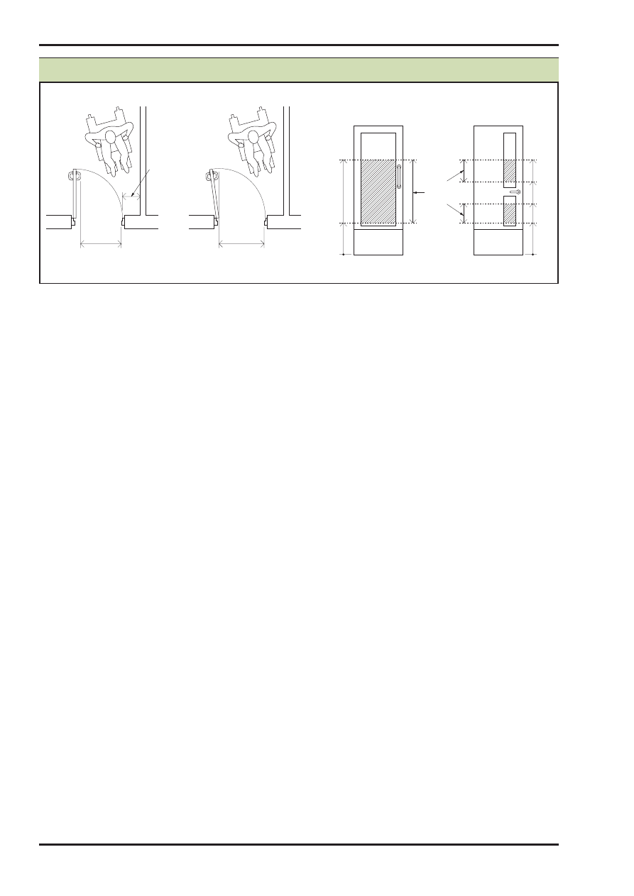
Manually operated non-powered
entrance doors
Design considerations
2.14 Self-closing devices on manually
operated non-powered swing doors
disadvantage many people who have
limited upper body strength, are
pushing prams or are carrying heavy
objects.
2.15 A space alongside the leading
edge of a door should be provided to
enable a wheelchair user to reach and
grip the door handle, then open the
door without releasing hold on the
handle and without the footrest
colliding with the return wall.
2.16 Door furniture on manually
operated non-powered doors should be
easy to operate by people with limited
manual dexterity, and be readily
apparent against the background of the
door.
Provisions
2.17 Manually operated non-powered
entrance doors will satisfy Requirement
M1 or M2 if:
a.
the opening force at the leading
edge of the door is no greater than
20N;
b.
there is an unobstructed space of
at least 300mm on the pull side of the
door between the leading edge of the
door and any return wall, unless the
door is a powered entrance door (see
Diagram 9);
c.
where fitted with a latch, the door
opening furniture can be operated with
one hand using a closed fist, e.g. a
lever handle;
d.
all door opening furniture
contrasts visually with the surface of
the door and is not cold to the touch.
Powered entrance doors
Design considerations
2.18 Activation (e.g. motion sensors
and push buttons), safety features and
the time-lapse allowed for entry and
exit through powered door systems
should be carefully considered to suit
the needs of people who cannot react
quickly.
2.19 Manual controls for powered
entrance doors should be clearly
distinguishable against the background
and not located so that a person,
having used the control, needs to move
to avoid contact with the door as it
opens.
2.20 Revolving doors are not
considered accessible. They create
particular difficulties, and risk of injury,
for people with assistance dogs,
people with visual impairment or
mobility problems and for parents with
children and/or pushchairs. If a
revolving door is used, an entrance
door complying with 2.17 or 2.21
Approved Document M
Access into buildings other than dwellings
30
M1/M2
BUILDINGS OTHER THAN DWELLINGS
Diagram 9 Effective clear width and visibility requirements of doors
Effective clear width
(door stop to projecting ironmongery)
Effective clear width
(door stop to door leaf)
300 minimum
unless door
is power
operated
Minimum
zones of
visibility
500
500
800
1150
1500
1500

should be provided immediately
adjacent to it and signed to show that
it is accessible.
Provisions
2.21 Powered entrance doors will
satisfy Requirement M1 or M2 if:
a.
they have a sliding, swinging or
folding action controlled:
– manually by a push pad, card
swipe, coded entry, or remote
control, or
– automatically by a motion sensor
or other proximity sensor, e.g. a
contact mat;
b.
when installed, automatic sensors
are set so that automatically operated
doors open early enough, and stay
open long enough, to permit safe entry
and exit;
c.
when they are swing doors that
open towards people approaching the
doors, visual and audible warnings are
provided to warn people of their
automatic operation when both opening
and shutting;
d.
they incorporate a safety stop
that is activated if the doors begin to
close when a person is passing
through;
e.
they revert to manual control or
fail safe in the open position in the
event of a power failure;
f.
when open, they do not project
into any adjacent access route;
g.
any manual controls for powered
door systems are located between
750mm and 1000mm above floor level,
operable with a closed fist and, when
on the opening side of the door, are set
back 1400mm from the leading edge of
the door when fully open and contrast
visually with the background against
which they are seen.
Glass entrance doors and glazed
screens
Note: Where there appears to be a
conflict between the guidance in Part
M and Part N, Part M takes
precedence, see the Notes to the
Requirements.
Design considerations
2.22 People with visual impairment
should be in no doubt as to the
location of glass entrance doors,
especially when they are within a
glazed screen. The choice of a different
style of manifestation for the door and
the glazed screen can help to
differentiate between them.
2.23 The presence of the door should
be apparent not only when it is shut
but also when it is open. Where it can
be held open, steps should be taken to
avoid people being harmed by walking
into the door.
Provisions
2.24 Glass entrance doors and glazed
screens will satisfy Requirement M1 or
M2 if:
a.
they are clearly defined with
manifestation on the glass at two
levels, 850 to 1000mm and 1400 to
1600mm above the floor, contrasting
visually with the background seen
through the glass (both from inside and
outside) in all lighting conditions;
b.
manifestation takes the form of a
logo or sign at least 150mm high
(repeated if on a glazed screen), or a
decorative feature such as broken lines
or continuous bands, at least 50mm
high;
c.
glazed entrance doors, where
adjacent to, or forming part of, a
glazed screen, are clearly differentiated
from it by the provision of a high-
contrast strip at the top, and on both
sides;
d.
glass entrance doors, where
capable of being held open, are
protected by guarding to prevent the
leading edge constituting a hazard.
Entrance lobbies
Design considerations
2.25 There are a number of reasons for
providing a lobby:
•
to limit air infiltration
Access into buildings other than dwellings
Approved Document M
31
M1/M2
BUILDINGS OTHER THAN DWELLINGS

•
to maintain comfort by controlling
draughts
• to
increase
security
•
to provide transitional lighting.
2.26 The provision of a lobby may
make it possible for an external door to
have a self-closing device with a lower
power size rating than might otherwise
be the case. However, even in these
circumstances, it may not be possible
for the entrance door to meet the
opening force criterion of 20N
maximum (see 2.9).
2.27 The lobby should be large enough
and of a shape to allow a wheelchair
user or a person pushing a pram to
move clear of one door before opening
the second door. The lobby should
also be capable of accommodating a
companion helping a wheelchair user
to open doors and guide the wheelchair
through. The minimum length of the
lobby is related to the chosen door
size, the swing of each door, the
projection of the door into the lobby
and the size of an occupied wheelchair
with a companion pushing. Where both
doors of a lobby are automatic sliding
doors, the length can be reduced as no
door swings are involved, nor is space
required for manual operation.
Similarly, if ‘reduced swing’ door sets
are used, the length can be reduced
because the projection of the door into
the lobby is reduced.
2.28 The aim should be to reduce
potential hazards from local
obstructions within the lobby and
minimise distracting reflections from
glazing. It is also desirable if rainwater
from shoes or the wheels of
wheelchairs is not taken into the
building where it becomes a potential
slip hazard, e.g. by the use of cleaning
mats.
Provisions
2.29 Entrance lobbies will satisfy
Requirement M1 or M2 if:
a.
their length with single swing
doors is in accordance with
Diagram 10;
b.
their length with double swing
doors is at least (DP1 + DP2 +
1570mm);
c.
their width (excluding any
projections into the space) is at least
1200mm (or (DL1 or DL2) + 300mm)
whichever is the greater when single
leaf doors are used, and at least
1800mm when double leaf doors are
used;
d.
glazing within the lobby does not
create distracting reflections;
e.
floor surface materials within the
lobby do not impede the movement of
wheelchairs, e.g. not coir matting, and
changes in floor materials do not create
a potential trip hazard;
f.
the floor surface helps to remove
rainwater from shoes and wheelchairs;
g.
where mat wells are provided, the
surface of the mat is level with the
surface of the adjacent floor finish;
h.
any columns, ducts and similar
full height elements that project into
the lobby by more than 100mm are
protected by a visually contrasting
guard rail.
Approved Document M
Access into buildings other than dwellings
32
M1/M2
BUILDINGS OTHER THAN DWELLINGS
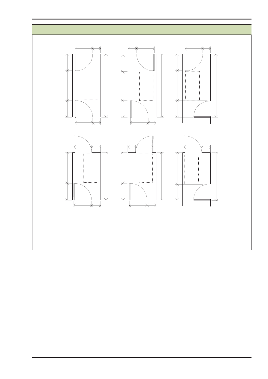
Access into buildings other than dwellings
Approved Document M
33
M1/M2
BUILDINGS OTHER THAN DWELLINGS
DL1 and DL2 = door leaf dimensions of the doors to the lobby
DP1 and DP2 = door projection into the lobby (normally door leaf size)
L = minimum length of lobby, or length up to door leaf for side entry lobby
“a” = at least 300mm wheelchair access space (can be increased to reduce L)
1570 = length of occupied wheelchair with a companion pushing (or a large scooter)
NB: For every 100mm increase above 300mm in the dimension “a” (which gives a greater overlap of the wheelchair footprint over
the door swing), there can be a corresponding reduction of 100mm in the dimension L, up to a maximum of 600mm reduction.
DL2
DP2
1570
L
DP1
"a"
DL1
"a"
DL2
1570
L
DP1
DL1
"a"
DL2
1570
L
DL1
DL2
DP2
1570
L
DP1
"a"
DL1
"a"
DL2
DP2
1570
L
"a"
DL1
"a"
"a"
DL2
DP2
1570
L
"a"
DL1
"a"
Diagram 10 Key dimensions for lobbies with single leaf doors

HORIZONTAL AND VERTICAL
CIRCULATION IN BUILDINGS
OTHER THAN DWELLINGS
Objective
3.1
The objective is for all people to
travel vertically and horizontally within
buildings conveniently and without
discomfort in order to make use of all
relevant facilities. This objective relates
in the main, but not exclusively, to the
provision of sufficient space for
wheelchair manoeuvre and design
features that make it possible for
people to travel independently within
buildings.
Entrance hall and reception area
Design considerations
3.2
As the entrance hall is the first
point of contact with a building’s
activities and resources, the reception
area in particular should not only be
easily accessible but also convenient to
use.
3.3
Where a service building has a
reception or sales counter, there should
be convenient access to it and part of
it should be at a level suitable for a
wheelchair user or a seated person.
Any lower section should also be
wheelchair-accessible on the reception
side.
3.4
Designers should also be aware
that glazed screens in front of the
reception point, or light sources or
reflective wall surfaces, such as glazed
screens, located behind the reception
point, could compromise the ability of a
person with a hearing impairment to lip
read or follow sign language.
3.5
It should be possible for
information about the building to be
easily obtained from a reception point
or gathered from notice boards and
signs.
Note: Guidance on aids to
communication is available in BS 8300,
and on the use of signs in the ‘Sign
Design Guide’.
Provisions
3.6
An entrance hall and reception
area will satisfy Requirement M1 or M2
if:
a.
any reception point is located
away from the principal entrance (while
still providing a view of it) where there
is a risk that external noise will be a
problem;
b.
any reception point is easily
identifiable from the entrance doors or
lobby, and the approach to it is direct
and free from obstructions;
c.
the design of the approach to any
reception point allows space for
wheelchair users to gain access to the
reception point;
d.
the clear manoeuvring space in
front of any reception desk or counter
is 1200mm deep and 1800mm wide if
there is a knee recess at least 500mm
deep, or 1400mm deep and 2200mm
wide if there is no knee recess;
e.
any reception desk or counter is
designed to accommodate both
standing and seated visitors such that
at least one section of the counter is at
least 1500mm wide, with its surface no
higher than 760mm, and a knee recess,
not less than 700mm, above floor level;
f.
any reception point is provided
with a hearing enhancement system,
e.g. an induction loop;
g.
the floor surface is slip resistant.
Internal doors
Design considerations
3.7
Since doors are potential barriers,
their use should be avoided whenever
appropriate. If doors are required, the
use of self-closing devices should be
minimised (particularly in parts of
buildings used by the general public)
since, as described in 2.14, they
disadvantage many people who have
limited upper body strength, are
pushing prams or are carrying heavy
objects. Where closing devices are
needed for fire control, electrically
Approved Document M
34
M
Section 3
Horizontal and vertical circulation in buildings other than dwellings
M1/M2
BUILDINGS OTHER THAN DWELLINGS

powered hold open devices or swing-
free closing devices should be used as
appropriate. These are devices whose
closing mechanism is only activated in
case of emergency. Low energy
powered door systems may be used in
locations not subject to frequent use or
heavy traffic as the opening and
closing action is relatively slow.
3.8
The presence of doors, whether
open or closed, should be apparent to
visually impaired people through the
careful choice of colour and material
for the door and its surroundings. For
example, when a door is open, people
with impaired sight should be able to
identify the door opening within the
wall, as well as the leading edge of the
door.
3.9
Other design considerations for
internal doors are as set out in 2.14 to
2.16 under ‘Manually operated non-
powered entrance doors’ and should
be referred to for guidance.
Note: Guidance is available in BS
8300 on:
– electrically powered hold-open
devices
– swing-free systems
– low energy powered door
systems.
Provisions
3.10 Internal doors will satisfy
Requirement M1 or M2 if:
a.
where needing to be opened
manually, the opening force at the
leading edge of the door does not
exceed 20N;
b.
the effective clear width through a
single leaf door, or one leaf of a double
leaf door, is in accordance with Table 2
and Diagram 9;
c.
there is an unobstructed space of
at least 300mm on the pull side of the
door between the leading edge of the
door and any return wall, unless the
door has power-controlled opening or it
provides access to a standard hotel
bedroom;
d.
where fitted with a latch, the door
opening furniture can be operated with
one hand using a closed fist, e.g. a
lever handle;
e.
all door opening furniture
contrasts visually with the surface of
the door;
f.
the door frames contrast visually
with the surrounding wall;
g.
the surface of the leading edge of
any door that is not self-closing, or is
likely to be held open, contrasts
visually with the other door surfaces
and its surroundings;
h.
where appropriate in door leaves
or side panels wider than 450mm,
vision panels towards the leading edge
of the door have vertical dimensions
which include at least the minimum
zone, or zones, of visibility between
500mm and 1500mm from the floor, if
necessary interrupted between 800mm
and 1150mm above the floor, e.g. to
accommodate an intermediate
horizontal rail (see Diagram 9).
i.
when of glass, they are clearly
defined with manifestation on the glass
at two levels, 850 to 1000mm and 1400
to 1600mm, contrasting visually with
the background seen through the glass
in all lighting conditions (see 2.24(b) for
details of manifestation);
j.
when of glass or fully glazed, they
are clearly differentiated from any
adjacent glazed wall or partition by the
provision of a high-contrast strip at the
top, and on both sides;
k.
fire doors, particularly those in
corridors, are held open with an
electro-magnetic device, but self-close
when:
– activated by smoke detectors
linked to the door individually, or
to a main fire/smoke alarm
system;
– the power supply fails;
– activated by a hand-operated
switch;
l.
fire doors, particularly to
individual rooms, are fitted with swing-
free devices that close when activated
Approved Document M
35
Horizontal and vertical circulation in buildings other than dwellings
M1/M2
BUILDINGS OTHER THAN DWELLINGS

by smoke detectors or the building’s
fire alarm system, or when the power
supply fails;
m.
any low energy powered swing
door system is capable of being
operated in manual mode, in powered
mode, or in power-assisted mode.
Corridors and passageways
Design considerations
3.11 Corridors and passageways
should be wide enough to allow people
with buggies, people carrying cases or
people on crutches to pass others on
the access route. Wheelchair users
should also have access to adjacent
rooms and spaces, be able to pass
other people and, where necessary,
turn through 180°. Corridors narrower
than indicated in this guidance, or
localised narrowing (e.g. at archways)
might be reasonable in some locations,
such as in existing buildings, or in
some extensions.
3.12 In order to help people with visual
impairment to appreciate the size of a
space they have entered, or to find
their way around, there should be a
visual contrast between the wall and
the ceiling, and between the wall and
the floor. Such attention to surface
finishes should be coupled with good
natural and artificial lighting design.
3.13 Good acoustic design should be
employed to achieve an acoustic
environment that is neither too
reverberant nor too absorbent so that
announcements and conversations can
be heard clearly.
Provisions
3.14 Corridors and passageways will
satisfy Requirement M1 or M2 if:
a.
elements such as columns,
radiators and fire hoses, do not project
into the corridor, or where this is
unavoidable, a means of directing
people around them, such as a visually
contrasting guard rail, is provided;
b.
they have an unobstructed width
(excluding any projections into the
space) along their length of at least
1200mm;
c.
where they have an unobstructed
width of less than 1800mm, they have
passing places at least 1800mm long
and with an unobstructed width of at
least 1800mm at reasonable intervals,
e.g. at corridor junctions, to allow
wheelchair users to pass each other;
d.
the floor is level or predominantly
level (with a gradient no steeper than
1:60), with any section with a gradient
of 1:20 or steeper designed as an
internal ramp and in accordance with
Table 1 and Diagram 3;
e.
where a section of the floor has a
gradient, in the direction of travel,
steeper than 1:60, but less steep than
1:20, it rises no more than 500mm
without a level rest area at least
1500mm long (with a gradient no
steeper than 1:60);
f.
any sloping section extends the
full width of the corridor or, if not, the
exposed edge is clearly identified by
visual contrast and, where necessary,
protected by guarding;
g.
any door opening towards a
corridor, which is a major access route
or an escape route, should be recessed
so that when fully open, it does not
project into the corridor space, except
where the doors are to minor utility
facilities, such as small store rooms
and locked duct cupboards;
h.
any door from a unisex
wheelchair-accessible toilet projects
when open into a corridor that is not a
major access route or an escape route,
provided the corridor is at least
1800mm wide at that point;
i.
on a major access route or an
escape route, the wider leaf of a series
of double doors with leaves of unequal
width is on the same side of the
corridor throughout the length of the
corridor;
j.
floor surface finishes with
patterns that could be mistaken for
steps or changes of level are avoided;
k.
floor finishes are slip resistant;
l.
any glazed screens alongside a
corridor are clearly defined with
manifestation on the glass at two
Approved Document M
36
Horizontal and vertical circulation in buildings other than dwellings
M1/M2
BUILDINGS OTHER THAN DWELLINGS

levels, 850 to 1000mm and 1400 to
1600mm, contrasting visually with the
background seen through the glass in
all lighting conditions (see 2.24(b) for
details of manifestation);
Note: In respect of 3.14(b), for school
buildings, the preferred corridor width
dimension is 2700mm where there are
lockers within the corridor.
Internal lobbies
Design considerations
3.15 An internal lobby should allow a
wheelchair user, with or without a
companion, or a person pushing a
pram or buggy, to move clear of one
door before attempting to open the
second door, as indicated in 2.27,
under ‘External lobbies’.
Provisions
3.16 Internal lobbies will satisfy
Requirement M1 or M2 if:
a.
their length with single swing
doors is in accordance with Diagram
10;
b.
their length with double swing
doors is at least (DP1 + DP2 +
1570mm);
c.
their width (excluding any
projections into the space) is at least
1200mm (or (DL1 or DL2) + 300mm)
whichever is the greater when single
leaf doors are used, and at least
1800mm when double leaf doors are
used;
d.
glazing within the lobby does not
create distracting reflections;
e.
any junctions of floor surface
materials at the entrance to the lobby
area do not create a potential trip
hazard;
f.
any columns, ducts and similar
full height elements that project into
the lobby by more than 100mm are
protected by a visually contrasting
guard rail.
Vertical circulation within the
building
Design considerations
3.17 A passenger lift is the most
suitable means of vertical access and
should be provided wherever possible.
However, given the space constraints
in some buildings, it may not always be
possible to install the type and size of
passenger lift that would be suitable for
use by all, and other options may need
to be considered to provide for users
with mobility impairments.
3.18 Signs indicating the location of a
lifting device accessible by mobility-
impaired people should be clearly
visible from the building entrance.
Additionally, a sign identifying the floor
reached should be provided on each
landing in a location that can be easily
seen from the lifting device and is
designed so that it contrasts visually
with its surroundings;
3.19 Whatever lifting device is chosen,
internal stairs should always be
provided as an alternative means of
vertical access, and designed to suit
ambulant disabled people and those
with impaired sight.
3.20 A ramp may also be provided on
an internal circulation route to a
suitable lifting device, if a change of
level is unavoidable.
Provision of lifting devices
Design considerations
3.21 For all buildings, a passenger lift
is the most suitable form of access for
people moving from one storey to
another.
3.22 For existing buildings, and in
exceptional circumstances for new
developments with particular
constraints (e.g. a listed building, or an
infill site in a historic town centre),
where a passenger lift cannot be
accommodated, a vertical lifting
platform (platform lift), although not
equivalent to a passenger lift, may be
considered as an alternative option to
provide access for persons with
impaired mobility. The case for using
Approved Document M
37
Horizontal and vertical circulation in buildings other than dwellings
M1/M2
BUILDINGS OTHER THAN DWELLINGS

such a lifting device should be argued
in the Access Statement.
3.23 In exceptional circumstances in
an existing building, a wheelchair
platform stairlift may be considered,
provided its installation does not
conflict with requirements for means of
escape. The case for installing a
wheelchair platform stairlift should be
argued in the Access Statement.
Provisions
3.24 The provision of lifting devices
will satisfy Requirement M1 or M2 if:
a.
new developments have a
passenger lift serving all storeys;
b.
new developments, where due to
site constraints a passenger lift cannot
be accommodated to provide access to
persons with impaired mobility, have a
lifting platform, of a type designed for
the vertical height to be travelled;
c.
existing buildings have a
passenger lift serving all storeys or, if a
passenger lift cannot reasonably be
accommodated to provide access to
persons with impaired mobility, they
have a lifting platform, of a type
designed for the vertical height to be
travelled;
d.
existing buildings have a
wheelchair platform stairlift serving an
intermediate level or a single storey,
only in exceptional circumstances.
General requirements for lifting
devices
Design considerations
3.25 In selecting the appropriate lifting
device care should be taken to ensure
it is fit for purpose. Relevant
legislation includes the Lift Regulations
1997 SI 1997/831, the Lifting
Operations and Lifting Equipment
Regulations 1998 SI 1998/2307, the
Provision and Use of Work Equipment
Regulations 1998 SI 1998/2306 and the
Management of Health and Safety at
Work Regulations 1999 SI 1999/3242.
3.26 The illumination in the passenger
lift car, on the lifting platform or on the
wheelchair platform stairlift should
minimise glare, reflection, confusing
shadows or pools of light and dark.
3.27 All users including wheelchair
users should be able to reach and use
the controls that summon and direct
the lifting device.
Note: Further guidance is available in
BS 8300.
Provisions
3.28 The installation of lifting devices
will satisfy Requirement M1 or M2 if:
a.
there is an unobstructed
manoeuvring space of 1500mm x
1500mm, or a straight access route
900mm wide, in front of each lifting
device;
b.
the landing call buttons are
located between 900mm and 1100mm
from the floor of the landing and at
least 500mm from any return wall;
c.
the landing call button symbols,
where provided, and lifting device
control button symbols are raised to
facilitate tactile reading;
d.
all call and control buttons
contrast visually with the surrounding
face plate, and the face plate similarly
contrasts with the surface on which it
is mounted;
e.
the floor of the lifting device
should not be of a dark colour and
should have frictional qualities similar
to, or higher than, the floor of the
landing;
f.
a handrail is provided on at least
one wall of the lifting device with its
top surface at 900mm (nominal) above
the floor and located so that it does
not obstruct the controls or the mirror;
g.
a suitable emergency
communication system is fitted.
Passenger lifts
Design considerations
3.29 A wheelchair user needs sufficient
space and time to enter and leave a
passenger lift, particularly when sharing
it with other people. Lift sizes should
therefore be chosen to suit the
anticipated density of use of the
Approved Document M
38
Horizontal and vertical circulation in buildings other than dwellings
M1/M2
BUILDINGS OTHER THAN DWELLINGS
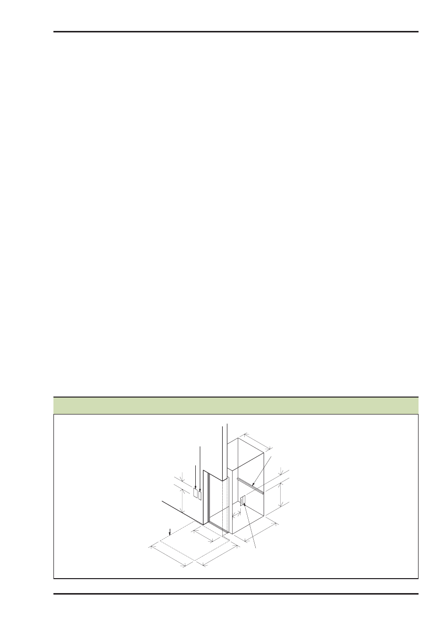
building and the needs of disabled
people. The minimum size lift car
shown in the provisions below
accommodates a wheelchair user with
an accompanying person. A larger lift
size (2000mm wide by 1400mm deep)
will accommodate any type of
wheelchair together with several other
passengers. It will also allow a
wheelchair user or a person with a
walking frame to turn through 180°.
3.30 Lift door systems should be
designed to allow adequate time for
people, and any assistance dogs, to
enter or leave the lift without coming
into contact with closing doors.
3.31 People using or waiting for a lift
need audible and visual information to
tell them that a lift has arrived, which
floor it has reached and where in a
bank of lifts it is located.
3.32 The use of visually and
acoustically reflective wall surfaces can
cause discomfort for people with visual
and hearing impairment.
3.33 Where planning allows, lift cars
(used for access between two levels
only) may be provided with opposing
doors to allow a wheelchair user to
leave without reversing out.
Provisions
3.34 Passenger lifts will satisfy
Requirement M1 or M2 if:
a.
they conform to the requirements
of the Lift Regulations 1997, SI
1997/831 (Note: These regulations
may be met by compliance with,
among other things, the relevant British
Standards, EN 81 series of standards,
in particular BS EN 81-70: 2003 ‘Safety
rules for the construction and
installation of lifts - Particular
applications for passenger and good
passenger lifts’, or, where necessary,
by product certification issued by a
Notified Body.);
b.
they are accessible from the
remainder of the storey;
c.
the minimum dimensions of the
lift cars are 1100mm wide and 1400mm
deep (see Diagram 11);
d.
for lifts of a size that does not
allow a wheelchair user to turn around
within the lift car, a mirror is provided
in the lift car to enable a wheelchair
user to see the space behind the
wheelchair;
e.
power-operated horizontal sliding
doors provide an effective clear width
of at least 800mm (nominal);
f.
doors are fitted with timing
devices and re-opening activators to
allow adequate time for people and any
assistance dogs to enter or leave;
g.
car controls are located between
900mm and 1200mm (preferably
Approved Document M
39
Horizontal and vertical circulation in buildings other than dwellings
M1/M2
BUILDINGS OTHER THAN DWELLINGS
Unobstructed
wheelchair
turning space
Lift car controls with
tactile identification
Handrail
Sign showing storey
with tactile identification
Landing call buttons
with tactile identification
900 nominal
1200
Range for centre lines
of lift car controls
Range for centre lines
of landing call buttons
400
800 min.
1100
1400 min.
1100 min.
1500
1500
900
Diagram 11 Key dimensions associated with passenger lifts

1100mm) from the car floor and at least
400mm from any return wall;
h.
landing call buttons are located
between 900mm and 1100mm from the
floor of the landing and at least 500mm
from any return wall;
i.
lift landing and car doors are
distinguishable visually from the
adjoining walls;
j.
audible and visual indication of lift
arrival and location is provided in the
lift car and the lift lobby;
k.
areas of glass are identifiable by
people with impaired vision;
l.
where the lift is to be used to
evacuate disabled people in an
emergency, it conforms to the relevant
recommendations of BS 5588-8.
Lifting platforms
Design considerations
3.35 A lifting platform should only be
provided to transfer wheelchair users,
people with impaired mobility and their
companions vertically between levels
or storeys.
3.36 All users including wheelchair
users should be able to reach and use
the controls that summon and direct
the lifting platform.
3.37 People using or waiting for a
lifting platform need audible and visual
information to tell them that the
platform has arrived, and which floor it
has reached.
3.38 Lifting platforms travel slowly
between landings and may not be
suitable for lone users with certain
disabilities, e.g. those easily fatigued.
3.39 Lifting platforms are operated by
continuous pressure controls. In their
simplest form these may be
pushbuttons. However, another means
of continuous pressure control may
need to be considered to
accommodate the needs of users with
varying degrees of manual dexterity.
3.40 It is important when selecting a
lifting platform that due care and
attention is paid to its intended use
particularly if located in an
unsupervised environment. Where
management control cannot be
exercised, particular attention should
be paid to the product’s designed duty
cycle.
3.41 Where planning allows, lifting
platforms may be provided with
opposing doors when used for access
between two levels only, to allow a
wheelchair user to leave without
reversing out. In some cases, it may be
more convenient to provide a second
door at 90° to the first, in which case a
wider platform would be required.
3.42 The use of visually and
acoustically reflective wall surfaces
should be minimised within the lifting
platform to prevent discomfort for
people with visual and hearing
impairment.
Provisions
3.43 Lifting platforms will satisfy
Requirement M1 or M2 if:
a.
they conform to the requirements
of the Supply of Machinery (Safety)
Regulations 1992, S.I. 1992/3073
(Note: These regulations may be met
by compliance, among other things,
with the relevant British Standards,
EN81 series of standards or, where
necessary, by product certification
issued by a Notified Body. In the
absence of relevant harmonised
European standards, products with a
travel exceeding 3m must have a
product certificate issued by a Notified
Body);
b.
the vertical travel distance is:
i)
not more than 2m, where
there is no liftway enclosure
and no floor penetration;
ii)
more than 2m, where there
is a liftway enclosure;
c.
the rated speed of the platform
does not exceed 0.15m/s;
d.
lifting platform controls are
located between 800mm and 1100mm
from the floor of the lifting platform and
at least 400mm from any return wall;
e.
continuous pressure controls are
provided;
Approved Document M
40
Horizontal and vertical circulation in buildings other than dwellings
M1/M2
BUILDINGS OTHER THAN DWELLINGS

f.
landing call buttons are located
between 900mm and 1100mm from the
floor of the landing and at least 500mm
from any return wall;
g.
the minimum clear dimensions of
the platform are:
i)
800mm wide and 1250mm
deep, where the lifting
platform is not enclosed and
where provision is being
made for an unaccompanied
wheelchair user;
ii)
900mm wide and 1400mm
deep, where the lifting
platform is enclosed and
where provision is being
made for an unaccompanied
wheelchair user;
iii)
1100mm wide and 1400mm
deep where two doors are
located at 90° relative to
each other and where the
lifting platform is enclosed
or where provision is being
made for an accompanied
wheelchair user;
h.
doors have an effective clear
width of at least 900mm for an
1100mm wide and 1400mm deep lifting
platform and at least 800mm in other
cases;
i.
they are fitted with clear
instructions for use;
j.
the lifting platform entrances are
accessible from the remainder of the
storey;
k.
doors are distinguishable visually
from the adjoining walls;
l.
an audible and visual
announcement of platform arrival and
level reached is provided;
m.
areas of glass are identifiable by
people with impaired vision.
Wheelchair platform stairlifts
Design considerations
3.44 Wheelchair platform stairlifts are
only intended for the transportation of
wheelchair users and should only be
considered for conversions and
alterations where it is not practicable to
install a conventional passenger lift or
a lifting platform. Such stairlifts travel
up the string of a stair. They should not
be installed where their operation
restricts the safe use of the stair by
other people.
3.45 A wheelchair platform stairlift
allows a wheelchair user to travel
independently up and down stairs while
remaining seated in a wheelchair. A
wheelchair platform stairlift may be
more suitable for use in small areas
with a unique function, e.g. a small
library gallery, a staff rest room or a
training room.
3.46 Wheelchair platform stairlifts
travel slowly between landings and may
not be suitable for users with certain
disabilities, e.g. those easily fatigued.
3.47 Wheelchair platform stairlifts are
operated by continuous pressure
controls, commonly a joystick.
However, another means of continuous
pressure control may need to be
considered to accommodate users with
varying degrees of manual dexterity.
3.48 Wheelchair platform stairlifts are
only suitable where users can be
instructed in their safe use and where
management supervision can be
ensured.
Provisions
3.49 Wheelchair platform stairlifts will
satisfy Requirement M1 or M2 if:
a.
they conform to the requirements
of the Supply of Machinery (Safety)
Regulations 1992, S.I. 1992/3073
(Note: These regulations may be met
by compliance, among other things,
with the relevant British Standards,
EN81 series of standards or where
necessary Notified Body approval);
b.
in a building with a single
stairway, the required clear width of the
flight of stairs and landings for means
of escape is maintained when the
wheelchair platform is in the parked
position (see also Approved
Document B);
c.
the rated speed of the platform
does not exceed 0.15m/s;
Approved Document M
41
Horizontal and vertical circulation in buildings other than dwellings
M1/M2
BUILDINGS OTHER THAN DWELLINGS
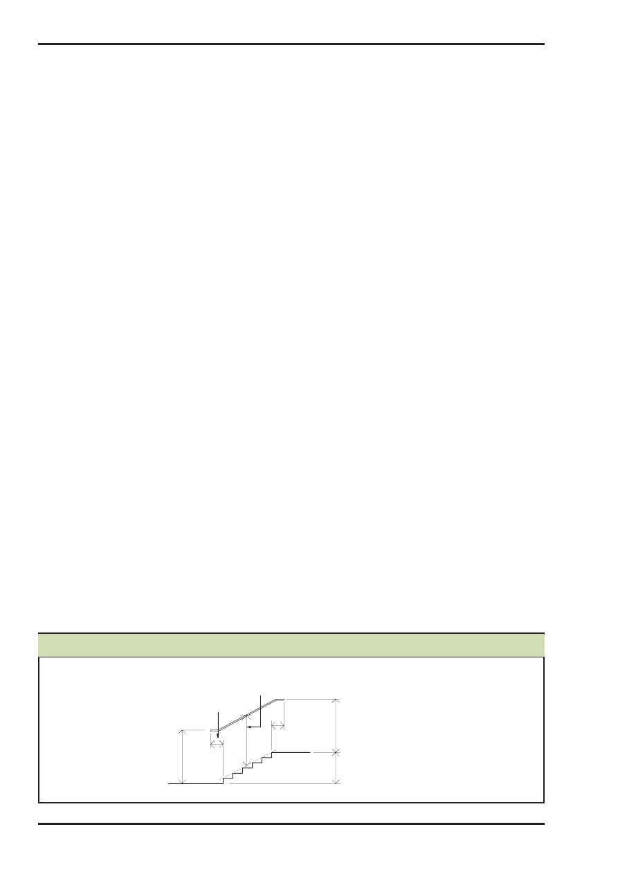
d.
continuous pressure controls are
provided;
e.
the minimum clear dimensions of
the platform are 800mm wide and
1250mm deep;
f.
they are fitted with clear
instructions for use;
g.
access with an effective clear
width of at least 800mm is provided;
h.
controls are designed to prevent
unauthorised use.
Internal stairs
Design considerations
3.50 With the exception of the need for
hazard warning surfaces on landings,
other design considerations for internal
stairs are as those for ‘Stepped
access’ (see 1.29 to 1.32). It is not
reasonable to require a hazard warning
surface at the head of internal stairs
since there is no recognised warning
surface for use internally which can be
guaranteed not to constitute a trip
hazard when used alongside flooring
surfaces with different frictional
resistance characteristics. However,
designers should be aware of the
potential risk of having a stair directly
in line with an access route. For
mobility-impaired people, a going of at
least 300mm is preferred.
Provisions
3.51 Internal stairs will satisfy
Requirement M1 or M2 if:
a.
they comply with provisions (a),
(b), (e) to (g), and (i) to (k) and (n) to (p)
of 1.33;
b.
a flight between landings normally
contains no more than 12 risers, but
exceptionally no more than 16 risers in
small premises where the plan area is
restricted (see Diagram 12);
c.
the rise of each step is between
150mm and 170mm, except in existing
buildings where, due to dimensional
constraints, the case for a different rise
is argued in the Access Statement;
d.
the going of each step is at least
250mm;
e.
the area beneath a stair where the
soffit is less than 2.1m above floor level
is protected as described in 1.39(b).
Note: For school buildings, in respect
of 3.51(c) and (d), the rise should not
exceed 170mm, with a preferred going
of 280mm. Also, for schools, refuges
should be provided for all stairs where
no other arrangement is in place (see
AD B, B1.xvi, and BS 5588-8 for details
of refuges).
Internal ramps
Design considerations
3.52 With the exception of issues
relating specifically to the external
environment, the design considerations
for internal ramps are as those for
‘Ramped access’ (see 1.19 to 1.25). It
is worth reiterating that ramps are not
necessarily safe and convenient for
ambulant disabled people. For
example, some people who can walk
Approved Document M
Horizontal and vertical circulation in buildings other than dwellings
42
M1/M2
BUILDINGS OTHER THAN DWELLINGS
900 to 1000
above pitch line
300 min.
300 min.
900 to
1100
900 to
1100
12 risers max.
(16 risers max. in small premises
where space is restricted)
Diagram 12 Internal stairs – key dimensions

but have restricted mobility find it more
difficult to negotiate a ramp than a
stair. Unless, therefore, a ramp is short,
has a shallow gradient and the rise is
no more than the minimum that can be
provided by two risers, steps should be
provided as well as a ramp.
Provisions
3.53 Internal ramps will satisfy
Requirement M1 or M2 if:
a.
they comply with provisions (a) to
(c), (e) to (j) and (l) to (m) for ramped
access in 1.26;
b.
where the change in level is
300mm or more, 2 or more clearly
signposted steps are provided in
addition to the ramp;
c.
where the change in level is no
greater than 300mm, a ramp is
provided instead of a single step;
d.
all landings are level, subject to a
maximum gradient of 1:60 along their
length;
e.
the area beneath a ramp where
the soffit is less than 2.1m above floor
level is protected as described in
1.39(b).
Handrails to internal steps, stairs
and ramps
Design considerations
3.54 The design considerations for
handrails are as those for ‘Handrails to
external stepped and ramped access’
in 1.34 to 1.36.
Provisions
3.55 Handrails to internal steps, stairs
and ramps will satisfy Requirement M1
or M2 if they comply with all the
provisions contained in 1.37.
Horizontal and vertical circulation in buildings other than dwellings
Approved Document M
43
M1/M2
BUILDINGS OTHER THAN DWELLINGS

FACILITIES IN BUILDINGS OTHER
THAN DWELLINGS
Objectives
4.1
The aim is for all people to have
access to, and the use of, all the
facilities provided within buildings.
They should also be able to participate
in the proceedings at
lecture/conference facilities and at
entertainment or leisure and social
venues, not only as spectators, but
also as participants and/or staff.
4.2
Where permanent or removable
seating is provided as part of the
design, allowance should be made for
disabled people to have a choice of
seating location at spectator events. It
should also be possible for them to
have a clear view of the activity taking
place while not obstructing the view of
others.
4.3
In refreshment facilities, bars and
counters (or sections of them) should
be at a level suitable for wheelchair
users. All floor areas, even when
located at different levels, should be
accessible.
4.4
A proportion of the sleeping
accommodation in hotels, motels and
student accommodation should be
designed for independent use by
wheelchair users. The remainder should
include facilities that make them
suitable for people who do not use a
wheelchair, but may have mobility,
sensory, dexterity or learning
difficulties.
Audience and spectator facilities
Design considerations
4.5
Audience and spectator facilities
fall primarily into three categories:
a. lecture/conference
facilities
b.
entertainment facilities (e.g.
theatres/cinemas)
c.
sports facilities (e.g. stadia).
Note: The guidance here relates mainly
to seating. For guidance on reception
and sales counters, refer to 3.2 to 3.5.
Audience facilities generally
4.6
Wheelchair users and those with
mobility or sensory impairment may
need to view or listen from a particular
side, or sit in the front for lip reading or
to read sign interpreters. They should
be provided with spaces into which
they can manoeuvre easily, and which
offer them a clear view of an event,
while ensuring they are not segregated
into special areas. Wheelchair users,
people who have difficulty in using
seats with fixed arms and those with
assistance dogs, should also have the
choice of sitting next to a
conventionally seated person or a
companion wheelchair user.
Consideration should be given to
providing an area next to certain seats
for an assistance dog to rest. By
having some removable seating at the
front and back of blocks of seats
(possibly in complete rows), greater
flexibility in location can be achieved
and a greater number of wheelchair
users than the minimum provision
shown in Table 3 can be
accommodated.
4.7
Greater spacing between rows of
seats at the rear of a block of seating,
or at the end of rows, may provide
extra legroom for people of large
stature. With several seats removed,
these locations may also be suitable for
wheelchair users. It is desirable for
seating to contrast visually with the
surroundings.
4.8
All users of facilities should be
able to locate suitable seating and
move safely and easily to and from the
seating area and ancillary
accommodation, such as lavatories,
dining rooms and bedroom suites.
Lecture/conference facilities
4.9
People with hearing impairments
should be able to participate fully in
conferences, committee meetings and
study groups. All people should be able
Approved Document M
44
Section 4
Facilities in buildings other than dwellings
M1
BUILDINGS OTHER THAN DWELLINGS
to use presentation facilities.
Consideration should be given to good
sight lines and the design and location
of lecture equipment (demonstration
table, lectern, projection screen) to
ensure that patterned walls, poor
interior lighting or very bright natural
back-lighting does not have a
detrimental effect on the ability of
people to receive information from a
sign language interpreter or a lip
speaker (see 4.32 to 4.34).
Entertainment, leisure and social
facilities
4.10 In facilities for entertainment, e.g.
theatres and cinemas, it is normal for
seating to be more closely packed than
in other types of auditoria. Care is
needed in the design and location of
wheelchair spaces so that all visitors
can enjoy the atmosphere. Reference
should also be made to ‘Technical
Standard for Places of Entertainment’.
Sports facilities
4.11 For guidance on integrating the
needs of disabled people into the
design of spectator facilities, in
particular the provision of, and access
to, suitable spaces for wheelchair users
in stadia, see ‘Guide to Safety at
Sports Grounds’, ‘Accessible stadia: a
good practice guide to the design of
facilities to meet the needs of disabled
spectators and other users’ and
‘Access for Disabled People’.
Provisions
4.12 Audience and spectator facilities
will satisfy Requirement M1 if:
For audience seating generally
a.
the route to wheelchair spaces is
accessible by wheelchair users;
b.
stepped access routes to
audience seating are provided with
fixed handrails (see 1.34 to 1.37 for
details of handrails);
c.
the minimum number of
permanent and removable spaces
provided for wheelchair users is in
accordance with Table 3;
d.
some wheelchair spaces (whether
permanent or created by removing
seats) are provided in pairs, with
standard seating on at least one side
(see Diagram 13);
e.
where more than two wheelchair
spaces are provided, they are located
to give a range of views of the event at
each side, as well as at front and back
of the seating area;
f.
the minimum clear space provided
for access to wheelchair spaces is
900mm;
g.
the clear space allowance for an
occupied wheelchair in a parked
position is 900mm wide by 1400mm
deep;
h.
the floor of each wheelchair space
is horizontal;
i.
some seats are located so that an
assistance dog can accompany its
Approved Document M
45
M1
Facilities in buildings other than dwellings
BUILDINGS OTHER THAN DWELLINGS
Table 3 Provision of wheelchair spaces
in audience seating
Seating Minimum
provision
capacity
of spaces for wheelchairs
Permanent Removable
Up to 600
1% of total seating
Remainder to make
capacity (rounded up)
a total of 6
Over 600
1% of total seating
Additional provision,
but less than capacity (rounded up)
if desired
10 000
Note:
For seating capacities of 10,000 or more, guidance is given in
‘Accessible stadia: a good practice guide to the design of
facilities to meet the needs of disabled spectators and other
users’.
In and out
In and out
In and out
Demonstration
table
Lectern
Wall mounted
projection screen
In and out
Diagram 13 An example of wheelchair
spaces in a lecture theatre

owner and rest in front of, or under, the
seat;
j.
standard seats at the ends of
rows and next to wheelchair spaces
have detachable, or lift-up, arms;
For seating on a stepped terraced floor
k.
wheelchair spaces at the back of
a stepped terraced floor are provided in
accordance with Diagrams 14 or 15,
the arrangement in Diagram 15 being
particularly suitable for entertainment
buildings, such as theatres or cinemas,
subject to the approval of the licensing
authority;
For lecture/conference facilities
l.
where a podium or stage is
provided, wheelchair users have access
to it by means of a ramp or lifting
platform;
m.
a hearing enhancement system in
accordance with 4.36 is provided for
people with impaired hearing.
Refreshment facilities
Design considerations
4.13 Refreshment facilities, such as
restaurants and bars, should be
designed so that they can be reached
and used by all people independently
or with companions. Staff areas should
also be accessible.
4.14 All public areas, including lavatory
accommodation, public telephones and
external terraces should be accessible.
Where premises contain self-service
and waiter service, all patrons should
have access to both.
4.15 In many refreshment facilities,
changes in level are used to
differentiate between different functions
or to create a certain atmosphere
through interior design. Changes of
floor level are acceptable provided the
different levels are accessible.
Provisions
4.16 Refreshment facilities will satisfy
Requirement M1 if:
a.
all users have access to all parts
of the facility;
b.
part of the working surface of a
bar or serving counter is permanently
accessible to wheelchair users, and at
a level of not more than 850mm above
the floor and, where necessary, part at
a higher level for people standing;
c.
the worktop of a shared
refreshment facility (e.g. for tea making)
is at 850mm above the floor with a
clear space beneath at least 700mm
above the floor (see Diagram 16) and
the delivery of water complies with
5.4(a) and (b);
d. a
wheelchair-accessible
threshold
(see 2.7(e)) is located at the transition
between an external seating area and
the interior of the facility.
Sleeping accommodation
Design considerations
4.17 Sleeping accommodation, where
provided for a significant number of
people, e.g. in hotels, motels and
student accommodation, should aim to
be convenient for all. People who use
wheelchairs are likely to require greater
provision of space and access to en-
suite sanitary accommodation. A
proportion of rooms will, therefore,
need to accommodate wheelchair
users. In student accommodation, it is
beneficial to have a wheelchair-
accessible toilet available for use by
disabled visitors.
4.18 Wheelchair users should be able
to reach all the facilities available
within the building. In general,
accessible bedrooms should be no less
advantageously situated than other
bedrooms. It would be beneficial if
entrance doors to wheelchair-
accessible bedrooms were powered-
opening, as this could avoid the need
for the 300mm access space adjacent
to the leading edge of the door.
4.19 Wheelchair-accessible bedrooms
should be sufficiently spacious to
enable a wheelchair user to transfer to
one side of a bed, with or without
assistance. Wheelchair users should be
able to manoeuvre around and use the
facilities in the room, and operate
switches and controls. They should
Approved Document M
46
Facilities in buildings other than dwellings
M1
BUILDINGS OTHER THAN DWELLINGS
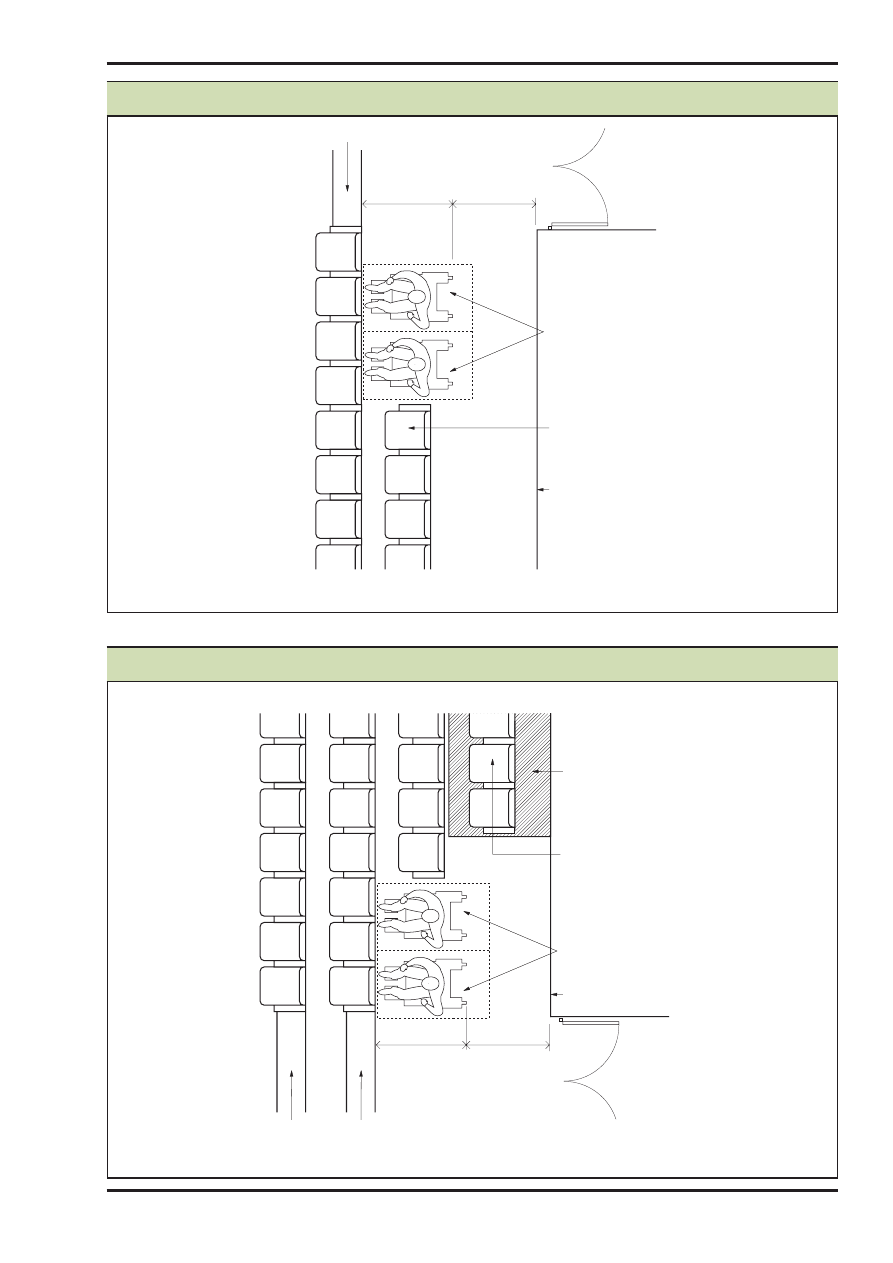
Approved Document M
47
Facilities in buildings other than dwellings
M1
BUILDINGS OTHER THAN DWELLINGS
1400 x 900 nominal
wheelchair spaces
More seats can be removed
if necessary to create more
wheelchair space
Steps
Rear wall
1100*
Aisle dimension
* Dimension derived from BS 8300
Diagram 14 Possible location of wheelchair spaces in front of a rear aisle
1400 x 900 nominal
wheelchair spaces
The rostrum as well as seats on
the rostrum and seats in the next
row can be removed to create
more wheelchair spaces
Steps
Steps
Rear wall
Rostrum
1100*
900
* Dimension derived from BS 8300
Diagram 15 An example of wheelchair space provision in a cinema or theatre
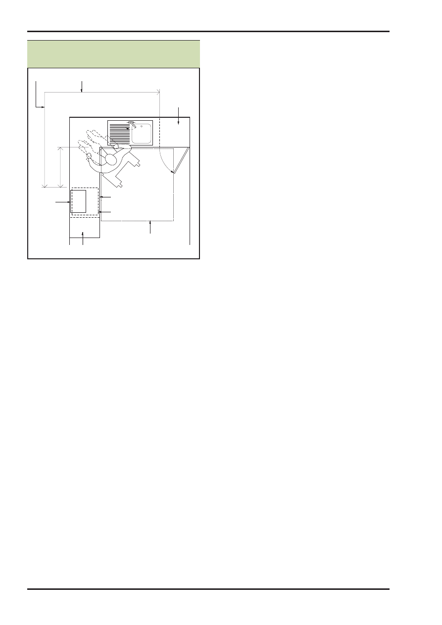
also be able to gain access to and
conveniently use sanitary
accommodation and, where provided,
balconies. En-suite sanitary facilities
are the preferred option for wheelchair-
accessible bedrooms. Unless there are
compelling reasons for not doing so,
there should be at least as many en-
suite shower rooms as en-suite
bathrooms, as mobility-impaired people
may find it easier to use a shower than
a bath. An en-suite shower room or
bathroom would benefit from having a
finger rinse basin adjacent to the WC,
as well as a wash basin or basin in a
vanitory unit.
4.20 It is also important to ensure that,
in all bedrooms, built-in wardrobes and
shelving are accessible and convenient
to use. It is an advantage if curtains
and blinds are provided with automatic,
or other remotely controlled opening
devices such as rods or pull cords.
4.21 Wheelchair users should also be
able to visit companions in other
bedrooms, for example when attending
conferences or when on holiday with
their families. In these instances,
bedrooms not designed for
independent use by a person in a
wheelchair need to have the outer door
wide enough to be accessible to a
wheelchair user.
4.22 For a proportion of wheelchair-
accessible bedrooms, it would be
useful to provide a connecting door to
an adjacent bedroom for a companion.
4.23 For people with limited manual
dexterity, electronic card-activated
locks for bedroom entrance doors and
lever taps in sanitary accommodation
can be an advantage.
Provisions
4.24 Sleeping accommodation will
satisfy Requirement M1 if:
For all bedrooms
a.
the effective clear width of the
door from the access corridor complies
with Table 2;
b.
swing doors, where provided for
built-in wardrobes and other storage
systems, open through 180°;
c.
handles on hinged and sliding
doors are easy to grip and operate and
contrast visually with the surface of the
door;
d.
openable windows and window
controls are located between 800 and
1000mm above the floor and are easy
to operate without using both hands
simultaneously;
e.
all bedrooms have a visual fire
alarm signal, in addition to the
requirements of Part B;
f.
any room numbers are indicated
in embossed characters;
For wheelchair-accessible bedrooms
g.
at least one wheelchair-accessible
bedroom is provided for every 20
bedrooms, or part thereof;
h. wheelchair-accessible
bedrooms
are located on accessible routes that
lead to all other available facilities
within the building;
i. wheelchair-accessible
bedrooms
are designed to provide a choice of
location and have a standard of
amenity equivalent to that of other
bedrooms;
Approved Document M
48
Facilities in buildings other than dwellings
M1
BUILDINGS OTHER THAN DWELLINGS
1500 x 1500
Wheelchair
turning space
Clear space under worktop
Work surface 850
above floor level
Microwave
oven
Refrigerator
under worktop
Floor unit
Floor unit
800
Diagram 16 An example of a shared
refreshment facility
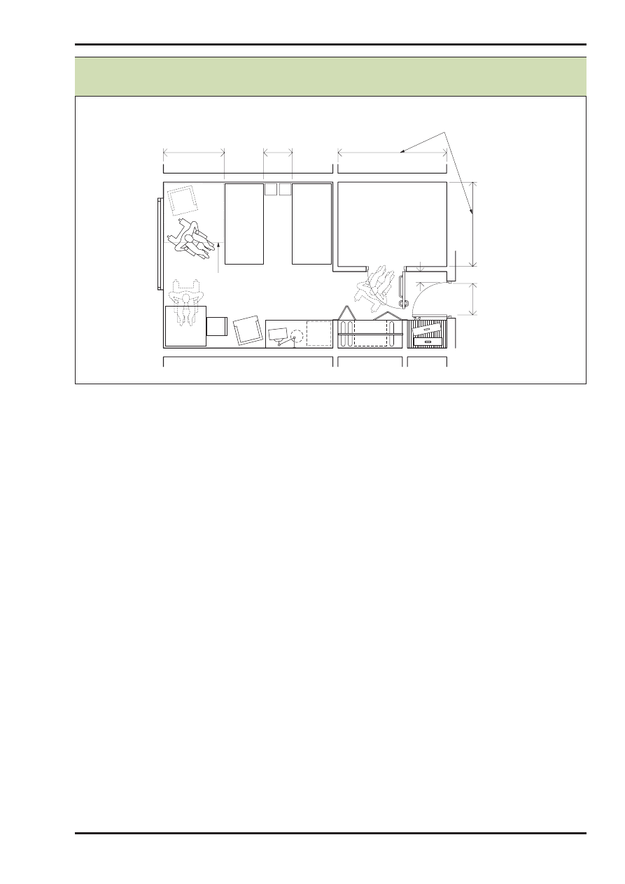
j.
the door from the access corridor
to a wheelchair-accessible bedroom
complies with the relevant provisions of
‘Internal doors’ (see 3.10), in particular
the maximum permissible opening
force, Table 2 and the need for a clear
space of 300mm from the leading edge
of the door to the side wall;
k.
the effective clear width of any
door to an en-suite bathroom or
shower room within the wheelchair-
accessible bedroom complies with
Table 2;
l.
the size of wheelchair-accessible
bedrooms allows for a wheelchair user
to manoeuvre at the side of a bed, then
transfer independently to it. An
example of a wheelchair-accessible
bedroom layout is shown in
Diagram 17;
m.
sanitary facilities, en-suite to a
wheelchair-accessible bedroom,
comply with the provisions of 5.15 to
5.21 for ‘Wheelchair-accessible
bathrooms’ or ‘Wheelchair-accessible
shower facilities’;
n.
wide angle viewers, where
provided in the entrance door to a
wheelchair-accessible bedroom, are
located at 1050mm and 1500mm above
floor level, to enable viewing by people
who are seated or standing;
o.
a balcony, where provided to a
wheelchair-accessible bedroom, has a
door whose effective clear width
complies with Table 2, has a level
threshold and has no horizontal
transoms between 900mm and
1200mm above the floor;
p.
there are no permanent
obstructions in a zone 1500mm back
from any balcony doors;
q.
an emergency assistance alarm
(together with a reset button) is located
in a wheelchair-accessible bedroom
and activated by a pull cord, sited so
that it can be operated both from the
bed and from an adjacent floor area;
r.
an emergency assistance call
signal outside an accessible bedroom
is located so that it can be easily seen
and heard by those able to give
assistance and, in any case, at a
central control point.
Approved Document M
49
Facilities in buildings other than dwellings
M1
BUILDINGS OTHER THAN DWELLINGS
300 min.
Effective
clear width
1500 min.
1500 x 1500
wheelchair turning space
See Section 5
for dimensions
Wheelchair-accessible
shower room or bathroom -
See Section 5 for details
700 min.
Diagram 17 One example of a wheelchair-accessible hotel bedroom with en-suite
sanitary facilities

Switches, outlets and controls
Design considerations
4.25 The key factors that affect the use
of switches, outlets and controls are
ease of operation, visibility, height and
freedom from obstruction. However,
there will be exceptions to height
requirements for some outlets, e.g.
those set into the floor in open plan
offices.
4.26 A consistent relationship with
doorways and corners will further
reinforce the ease with which people
manipulate switches and controls.
4.27 All users should be able to locate
a control, know which setting it is on,
and use it without inadvertently
changing its setting.
4.28 Controls that contrast visually
with their surroundings are more
convenient for visually impaired people,
as are light switches that are activated
by a large push pad. The colours red
and green should not be used in
combination as indicators of ‘on’ and
‘off’ for switches and controls. It may
be useful to use text or a pictogram to
clarify the purpose and status of
multiple switches and controls.
4.29 It is also an advantage if
individual switches on panels and on
multiple socket outlets are well
separated, or in the form of large touch
plates, to avoid the inadvertent
selection of an adjacent control by
visually impaired people and people
with limited dexterity.
Provisions
4.30 Switches, outlets and controls will
satisfy Requirement M1 if:
a.
wall-mounted socket outlets,
telephone points and TV sockets are
located between 400mm and 1000mm
above the floor, with a preference for
the lower end of the range;
b.
switches for permanently wired
appliances are located between 400mm
and 1200mm above the floor, unless
needed at a higher level for particular
appliances;
c.
all switches and controls that
require precise hand movements are
located between 750mm and 1200mm
above the floor;
d.
simple push button controls that
require limited dexterity, are not more
than 1200mm above the floor;
e.
pull cords for emergency alarm
systems are coloured red, located as
close to a wall as possible, and have
two red 50mm diameter bangles, one
set at 100mm and the other set
between 800mm and 1000mm above
the floor;
f.
controls that need close vision are
located between 1200mm and 1400mm
above the floor so that readings may
be taken by a person sitting or
standing (with thermostats at the top of
the range);
g.
socket outlets are located
consistently in relation to doorways
and room corners, but in any case no
nearer than 350mm from room corners;
h.
light switches for use by the
general public have large push pads
and align horizontally with door handles
within the range 900 to 1100mm, for
ease of location when entering a room;
i.
where switches described in
4.30(h) cannot be provided, lighting pull
cords are set between 900mm and
1100mm above floor level, and fitted
with a 50mm diameter bangle visually
contrasting with its background and
distinguishable visually from any
emergency assistance pull cord;
j
the operation of switches, outlets
and controls does not require the
simultaneous use of both hands,
except where this mode of operation is
necessary for safety reasons;
k.
switched socket outlets indicate
whether they are ‘on’;
l.
mains and circuit isolator
switches clearly indicate that they are
on or off;
m.
front plates contrast visually with
their backgrounds.
Approved Document M
50
Facilities in buildings other than dwellings
M1
BUILDINGS OTHER THAN DWELLINGS

Aids to communication
Design considerations
4.31 People will benefit most if there is
an integrated system for wayfinding,
public address and hearing
enhancement.
4.32 The appropriate choice of floor,
wall and ceiling surface materials and
finishes can help visually impaired
people appreciate the boundaries of
rooms or spaces, identify access
routes and receive information. For
example, glare and reflections from
shiny surfaces, and large repeating
patterns, should be avoided in spaces
where visual acuity is critical as they
will hamper communication for people
with impaired vision, and those who lip
read or use sign language. This would
apply to locations such as reception
areas with enquiry desks and speakers’
rostrums in lecture halls.
4.33 The type and quality of public
address, hearing enhancement and
telephone systems should be chosen
carefully to ensure intelligibility. The
design of the acoustic environment
should also ensure that audible
information can be heard clearly.
4.34 Artificial lighting should be
designed to give good colour rendering
of all surfaces, without creating glare,
or pools of bright light and strong
shadows. Where appropriate, lighting
should illuminate the face of a person
speaking, to make lip reading easier
where one-to-one communication is
necessary. Uplighters mounted at low
or floor level can disorientate some
visually impaired people and should be
avoided.
4.35 In order to obtain the full benefit
of attending public performances or
taking part in discussions, a person
with impaired hearing needs to receive
a signal that is amplified in both
volume and signal to noise ratio. The
three systems commonly used to
provide this enhanced level of sound
are induction loop, infrared and radio.
Sound field systems are also
increasingly being used, particularly in
educational establishments. In larger
spaces, provision needs to be made for
a permanent system, but in small
meeting rooms, a portable induction
loop would be acceptable. It should be
recognised that there is the danger
where adjacent spaces each have an
induction loop system that the signals
may overlap.
Note: Detailed guidance on surface
finishes, visual, audible and tactile
signs, as well as the characteristics
and appropriate choice and use of
hearing enhancement systems, is
available in BS 8300.
Provisions
4.36 Aids to communication will satisfy
Requirement M1 if:
a.
a clearly audible public address
system is supplemented by visual
information;
b.
provision for a hearing
enhancement system is installed in
rooms and spaces designed for
meetings, lectures, classes,
performances, spectator sport or films,
and at service or reception counters
when they are situated in noisy areas
or they are behind glazed screens;
c.
the presence of an induction loop
or infrared hearing enhancement
system is indicated by the standard
symbol;
d.
telephones suitable for hearing
aid users are clearly indicated by the
standard ear and ‘T’ symbol and
incorporate an inductive coupler and
volume control;
e.
text telephones for deaf and hard
of hearing people are clearly indicated
by the standard symbol;
f.
artificial lighting is designed to be
compatible with other electronic and
radio frequency installations.
Facilities in buildings other than dwellings
Approved Document M
51
M1
BUILDINGS OTHER THAN DWELLINGS

SANITARY ACCOMMODATION IN
BUILDINGS OTHER THAN
DWELLINGS
Objectives
5.1
In principle, suitable sanitary
accommodation should be available to
everybody, including sanitary
accommodation designed for
wheelchair users, ambulant disabled
people, people of either sex with
babies and small children, or people
encumbered by luggage.
5.2
In multi-storey buildings, the
consistent location of toilets on each
floor can help people with learning
difficulties to locate these facilities
easily.
Sanitary accommodation
generally
Design considerations
5.3
A number of issues need to be
considered in connection with all forms
of sanitary accommodation. These
relate to the needs of people with
visual or hearing impairments, people
with learning difficulties and people
whose lack of tactile sensitivity can
cause them to be injured by touching
hot surfaces. Taps and WC cubicle
doors should be operable by people
with limited strength or manual
dexterity and doors to cubicles should
be capable of being opened if a person
has collapsed against them while inside
the cubicle. Preferably, all doors to WC
cubicles and wheelchair-accessible
unisex toilets open out or, if they open
in, the door swing should not encroach
into the wheelchair turning space or
minimum activity space. Where
possible, light switches with large push
pads should be used in preference to
pull cords (see 4.28).
Provisions
5.4
Sanitary accommodation will
satisfy Requirement M1 or M3 if:
a.
any bath or wash basin tap is
either controlled automatically, or is
capable of being operated using a
closed fist, e.g. by lever action;
b.
terminal fittings comply with
Guidance Note G18.5 of the Guidance
Document relating to Schedule 2:
Requirements for Water Fittings, of the
Water Supply (Water Fittings)
Regulations 1999, SI 1999/1148;
c.
door handles and other
ironmongery comply with provisions
3.10(d) and (e) of ‘Internal doors’;
d.
WC compartment doors, and
doors to wheelchair-accessible unisex
toilets, changing rooms or shower
rooms are fitted with light action
privacy bolts so that they can be
operated by people with limited
dexterity and, if required to self-close,
can be opened using a force no greater
than 20N;
e.
WC compartment doors, and
doors to wheelchair-accessible unisex
toilets, changing rooms or shower
rooms have an emergency release
mechanism so that they are capable of
being opened outwards, from the
outside, in case of emergency;
f.
doors, when open, do not
obstruct emergency escape routes;
g.
any fire alarm emits a visual and
audible signal to warn occupants with
hearing or visual impairments;
h.
any emergency assistance alarm
system has:
i)
visual and audible indicators
to confirm that an
emergency call has been
received;
ii) a
reset
control
reachable
from a wheelchair and the
WC, or from the wheelchair
and the shower/changing
seat;
iii)
a signal that is
distinguishable visually and
audibly from the fire alarm.
Section 5
Approved Document M
Sanitary accommodation in buildings other than dwellings
52
M1/M3
BUILDINGS OTHER THAN DWELLINGS

i.
any lighting controls comply with
the provisions for ‘Switches and
controls’, see 4.30;
j.
any heat emitters are either
screened or have their exposed
surfaces kept at a temperature below
43°C;
k.
the surface finish of sanitary
fittings and grab bars contrasts visually
with background wall and floor finishes,
and there is also visual contrast
between wall and floor finishes.
Provision of toilet accommodation
Design considerations
5.5
Toilet accommodation needs to be
suitable, not only for disabled people,
but for all people who use the building.
For disabled people, suitable toilet
accommodation may take the form of a
specially designed cubicle in separate-
sex toilet washrooms, or a self-
contained unisex toilet. For wheelchair
users in particular, a self-contained
unisex toilet is always the preferred
option since, if necessary, a partner or
carer of a different sex can enter to
give assistance. Wheelchair-accessible
unisex toilets should always be
provided in addition to any wheelchair-
accessible accommodation in separate-
sex toilet washrooms. Wheelchair-
accessible unisex toilets should not be
used for baby changing.
5.6
The provision of an enlarged
cubicle in a separate-sex toilet
washroom can be of benefit to
ambulant disabled people, as well as
parents with children, and people (e.g.
those with luggage) who need an
enlarged space. In large building
developments, separate facilities for
baby changing and an enlarged unisex
toilet incorporating an adult changing
table are desirable.
Note: For specific guidance on the
provision of sanitary accommodation in
sports buildings, refer to ‘Access for
Disabled People’.
Provisions
5.7
The provision of toilet
accommodation will satisfy
Requirement M1or M3 if:
a.
where there is space for only one
toilet in a building, it is of a wheelchair-
accessible unisex type, but of greater
width to accommodate a standing
height wash basin;
b.
at least one wheelchair-accessible
unisex toilet is provided at each
location in a building where sanitary
facilities are provided for use by
customers and visitors to a building, or
by people working in the building;
c.
at least one WC cubicle is
provided in separate-sex toilet
accommodation for use by ambulant
disabled people;
d.
where there are 4 or more WC
cubicles in separate-sex toilet
accommodation, one of these is an
enlarged cubicle for use by people who
need extra space, in addition to any
provision under 5.7(c).
Wheelchair-accessible unisex
toilets
Design considerations
5.8
Wheelchair users should be able
to approach, transfer to, and use the
sanitary facilities provided within a
building. This requires the provision of
a wheelchair-accessible unisex toilet.
The relationship of the WC to the finger
rinse basin and other accessories
should allow a person to wash and dry
hands while seated on the WC. The
space provided for manoeuvring,
should enable wheelchair users to
adopt various transfer techniques that
allow independent or assisted use. It is
important that the transfer space
alongside the WC is kept clear to the
back wall. When transferring to and
from their wheelchair, some people
need horizontal support rails. The rail
on the open side is a drop-down rail,
but on the wall side, it can be a wall-
mounted grab rail (which is thought to
give a more rigid handhold) set at a
greater distance than normal from the
wall or, alternatively, a second drop-
Sanitary accommodation in buildings other than dwellings
Approved Document M
53
M1/M3
BUILDINGS OTHER THAN DWELLINGS

down rail in addition to the wall-
mounted grab rail where the grab rail is
spaced at the minimum distance from
the wall and therefore does not give the
same degree of support.
5.9
A unisex toilet is approached
separately from other sanitary
accommodation. It is more easily
identified than a wheelchair-accessible
cubicle in a separate-sex toilet
washroom and, provided it is used only
by disabled people, it is more likely to
be available when required. This is
particularly important as some disabled
people need to use a toilet more
frequently than other users. The time
needed to reach a wheelchair-
accessible toilet should therefore be
kept to a minimum when considering
the location of unisex toilet
accommodation. In addition, a unisex
toilet enables one or two assistants of
either sex to assist a disabled person.
Consideration should be given to
installing a chemical sanitary waste
disposal unit in wheelchair-accessible
WC accommodation. Some wheelchair
users find it difficult to use a standard-
height WC seat and, for them, it is
important that the WC pan can accept
a variable height toilet seat riser. WC
pans manufactured to the key
dimensions given in BS 5503-3 and BS
5504-4 are considered acceptable.
Note: More detailed guidance on the
various techniques used to transfer
from a wheelchair to a WC, as well as
appropriate sanitary and other fittings
is given in BS 8300.
Provisions
5.10 Wheelchair-accessible unisex
toilets will satisfy Requirement M1 or
M3 if:
a.
one is located as close as
possible to the entrance and/or waiting
area of the building;
b.
they are not located in a way that
compromises the privacy of users;
c.
they are located in a similar
position on each floor of a multi-storey
building, and allow for right- and left-
hand transfer on alternate floors;
d.
when more than one unisex toilet
is available in other than multi-storey
buildings, a choice of layouts suitable
for left-hand and right-hand transfer is
provided;
e.
when it is the only toilet facility in
the building, the width is increased
from 1.5m to 2m and it includes a
standing height wash basin, in addition
to the finger rinse basin associated
with the WC;
f.
they are located on accessible
routes that are direct and obstruction-
free;
g.
doors are preferably outward-
opening and are fitted with a horizontal
closing bar fixed to the inside face;
h.
any wheelchair user does not
have to travel:
i)
more than 40m on the same
floor, unless a greater
distance can be argued in
the Access Statement on the
grounds that the circulation
route is unobstructed, e.g.
by the installation of doors
with hold-open devices;
ii)
more than a 40m combined
horizontal distance where
the unisex toilet
accommodation is on
another floor of the building,
but is accessible by
passenger lift (if a lifting
platform is installed, vertical
travel to a unisex toilet is
limited to one storey);
i.
the minimum overall dimensions
of, and the arrangement of fittings
within, a wheelchair-accessible unisex
toilet, comply with Diagram 18;
j.
where the horizontal support rail
on the wall adjacent to the WC is set
with the minimum spacing from the
wall, an additional drop-down rail is
provided on the wall side at a distance
of 320mm from the centre line of
the WC;
k.
where the horizontal support rail
on the wall adjacent to the WC is set
so that its centre line is 400mm from
Approved Document M
54
M1/M3
BUILDINGS OTHER THAN DWELLINGS
Sanitary accommodation in buildings other than dwellings
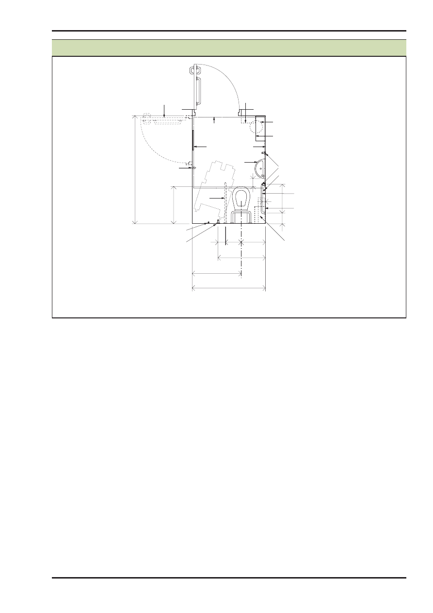
the centre line of the WC, there is no
additional drop-down rail;
l.
the heights and arrangement of
fittings in a wheelchair-accessible
unisex toilet comply with Diagram 19
and, as appropriate, Diagram 20;
m.
an emergency assistance alarm
system is provided, complying with 5.4;
n.
the emergency assistance call
signal outside the toilet compartment is
located so that it can be easily seen
and heard by those able to give
assistance;
o.
an emergency assistance pull
cord is easily identifiable (see 4.30(e))
and reachable from the WC and from
the floor close to the WC;
p.
any heat emitters are located so
that they do not restrict the minimum
clear wheelchair manoeuvring space,
nor the space beside the WC used for
transfer from the wheelchair to the WC;
q.
WC pans conform to BS 5503-3
or BS 5504-4 in terms of key
dimensions in order to accommodate
the use of a variable height toilet seat
riser (see 5.9);
r.
cisterns for WCs that will be used
by wheelchair users have their flushing
mechanism positioned on the open or
transfer side of the space, irrespective
of handing.
Toilets in separate-sex
washrooms
Design considerations
5.11 Ambulant disabled people should
have the opportunity to use a WC
compartment within any separate-sex
toilet washroom. The compartment
should be fitted with support rails, and
include a minimum activity space to
accommodate people who use
crutches, or otherwise have impaired
leg movements. The presence of this
Sanitary accommodation in buildings other than dwellings
Approved Document M
55
M1/M3
BUILDINGS OTHER THAN DWELLINGS
Mirror
Wall A
1500 x 1500
Wheelchair
turning space
Alternative door position
Sanitary dispenser
Disposal bin
Shelf
Alarm pull cord
Sanitary disposal unit
Wall mounted grab rail
Vertical grab rail
Alternative position
for alarm pull cord
(excluding any projecting heat emitters)
Clothes hooks
Drop-down
rail
Zone for shelf for
standing users
Note
Layout for right hand transfer to WC
Vertical grab rails
Finger rinse
basin
2200 min.
750
150
970
1000 min.
1500 min.
320
500
250
600
140-160
60 to
85
Diagram 18 Unisex wheelchair-accessible toilet with corner WC

facility helps avoid unnecessary travel
to unisex toilet accommodation. Some
ambulant disabled people find it
difficult to use a standard-height WC
seat and, for them, it is important that
the WC pan can accept a variable
height toilet seat riser.
5.12 Separate-sex toilet washrooms
above a certain size should also
include an enlarged WC cubicle for use
by people who need extra space, e.g.
parents with children and babies,
people carrying luggage and also
ambulant disabled people.
Approved Document M
Sanitary accommodation in buildings other than dwellings
56
M1/M3
BUILDINGS OTHER THAN DWELLINGS
600 grab rail
each side of
mirror
Height of independent wash basin
and location of associated fittings, for
wheelchair users and standing people
Mirror located away from wash basin
suitable for seated and standing people
(Mirror and associated fittings used
within a WC compartment or serving a
range of compartments)
A. For people standing
B. For use from WC
Automatic
hand dryer
Shaver point
Mirror
Centre of
grab rail
1100
600-700
1600
min.
height to rim
of basin
A. 780 to 800
B. 720 to 740
800-1000
600
1600 min.
Diagram 20 Heights of various fittings in toilet accommodation
Sanitary dispenser
with coin slot
between 750 and 1000
above the floor
Disposal bin
Alarm pull cord
with two red bangles
one at 100, the other
at 800 to 1000 above
floor level
Shelf
HD SD
PT AR
TP
Location of
shelf at 950
above floor
level
Grab rails
Grab rails
*Height subject to manufacturing tolerance of WC pan
HD: Possible position for automatic hand dryer (see also Diag 21)
SD: Soap
dispenser
PT: Paper towel dispenser
AR: Alarm reset button
TP: Toilet paper dispenser
Height of drop-down rails to be the same as the other horizontal grab rails
300
300
680
1100
800-1000
720-740
480*
100
Diagram 19 Heights and arrangement of fittings in a unisex wheelchair-accessible
toilet (looking towards wall A in Diagram 18)
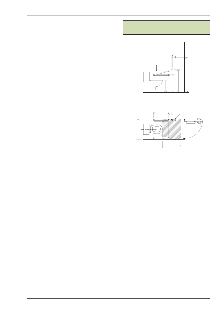
Consideration should be given to
installing a fold-down table, e.g. for
baby-changing. Standard WC
compartments should also have a
minimum manoeuvring space clear of
any door swing.
5.13 Where a separate-sex toilet
washroom can be accessed by
wheelchair users, it should be possible
for them to use both a urinal, where
appropriate, and a washbasin at a
lower height than is provided for other
users. The relative numbers of urinals
for men and WC compartments for
women has been the subject of recent
research. In general, the findings
indicate that there should be at least
the same number of WCs (for women)
as urinals (for men) and for some
buildings types, e.g. large retail
buildings, at least twice as many.
Consideration should be given to
providing a low level urinal for children
in male washrooms.
Note: More detailed guidance on
appropriate sanitary and other fittings
is given in BS 8300.
Provisions
5.14 WC compartments within
separate-sex toilet washrooms will
satisfy Requirement M1 or M3 if:
a.
the swing of any inward opening
doors to standard WC compartments is
such that a 450mm diameter
manoeuvring space is maintained
between the swing of the door, the WC
pan and the side wall of the
compartment;
b.
the minimum dimensions of
compartments for ambulant disabled
people, including the activity space,
and the arrangement of grab bars and
other fittings within the compartment,
comply with Diagram 21;
c.
doors to compartments for
ambulant disabled people are
preferably outward-opening and are
fitted with a horizontal closing bar fixed
to the inside face;
d.
an enlarged compartment for
those who need extra space (based on
the compartment for ambulant disabled
people) is 1200mm wide and includes a
horizontal grab bar adjacent to the WC,
a vertical grab bar on the rear wall and
space for a shelf and fold-down
changing table;
e.
any compartment for use by
ambulant disabled people has a WC
pan that conforms to BS 5503-3 or BS
5504-4 in terms of key dimensions, in
order to accommodate the use of a
variable height toilet seat riser (see 5.9
and 5.11);
f. a
wheelchair-accessible
compartment (where provided) has the
same layout and fittings as the unisex
toilet;
g. any
wheelchair-accessible
washroom has at least one washbasin
with its rim set at 720 to 740mm above
the floor and, for men, at least one
urinal with its rim set at 380mm above
the floor, with two 600mm long vertical
grab bars with their centre lines at
1100mm above the floor, positioned
either side of the urinal.
Sanitary accommodation in buildings other than dwellings
Approved Document M
57
M1/M3
BUILDINGS OTHER THAN DWELLINGS
Clothes hook set at
1400 above floor level
600 long additional grab rail
if required
600 grab rail
set at 15° or
horizontal
as required
Height of toilet seat
500 min.
100
1400
480*
680 800
200 min.
800 min.
750 activity
space clear of
door swings
*Height subject to manufacturing tolerance of WC pan
Diagram 21 WC cubicle for ambulant
disabled people

Wheelchair-accessible changing
and shower facilities
Design considerations
5.15 A choice of shower layout
combined with the correct location of
shower controls and fittings will allow
disabled people to use the facilities
independently or be assisted by others
when necessary. For guidance on the
provision of en-suite shower facilities
associated with hotel bedrooms,
see 4.19.
5.16 In buildings where changing
facilities are associated with showering
facilities, many disabled people will be
content to use changing and shower
areas that are open but provided with
subdivisions, whereas some will require
the privacy and convenience of an
individual self-contained cubicle or
compartment. The dimensions of the
self-contained compartment allow
space for a helper. Any combined
facility should be divided into distinct
‘wet’ and ‘dry’ areas. In open changing
and shower areas, it may be difficult to
provide a configuration of handrails,
controls and seat suitable for all
disabled people to use. Individual self-
contained accommodation is therefore
preferred although, if it contains a WC,
it should not be the only wheelchair-
accessible toilet accommodation.
5.17 In the case of individual changing
rooms not associated with showering,
e.g. in clothes shops, the dimensions
and fittings recommended for an
individual self-contained changing
cubicle in a sports building should be
provided. In large building complexes,
such as retail parks and large sports
centres, there should be one
wheelchair-accessible unisex toilet
capable of including an adult changing
table.
Note 1: For sports buildings, details of
different types of changing and shower
facilities are given in ‘Access for
Disabled People’.
Note 2: More detailed guidance on
appropriate sanitary and other fittings
is given in BS 8300.
Provisions
5.18 Wheelchair-accessible changing
and shower facilities will satisfy
Requirement M1 or M3 if:
For changing and shower facilities
a.
a choice of layouts suitable for
left-hand and right-hand transfer is
provided when more than one
individual changing compartment or
shower compartment is available;
b.
they are provided with wall
mounted drop-down support rails and
wall mounted slip-resistant tip-up seats
(not spring-loaded);
c.
in communal shower facilities and
changing facilities, they are provided
with subdivisions that have the same
configuration of space and equipment
as for self-contained facilities but
without doors;
d.
in sports facilities, individual self-
contained shower facilities and
changing facilities are available in
addition to communal separate-sex
facilities;
e.
an emergency assistance pull
cord, complying with 4.30(e), is easily
identifiable and reachable from the wall
mounted tip-up seat, or from the floor;
f.
an emergency assistance alarm
system complying with 5.4(h) is
provided;
g.
facilities for limb storage are
included for the benefit of amputees;
For changing facilities
h.
the minimum overall dimensions
of, and the arrangement of equipment
and controls within, individual self-
contained changing facilities comply
with Diagram 22;
i.
when associated with shower
facilities, the floor of a changing area is
level and slip resistant when dry or
when wet;
j.
there is a manoeuvring space
1500mm deep in front of lockers in
self-contained or communal changing
areas;
Approved Document M
Sanitary accommodation in buildings other than dwellings
58
M1/M3
BUILDINGS OTHER THAN DWELLINGS
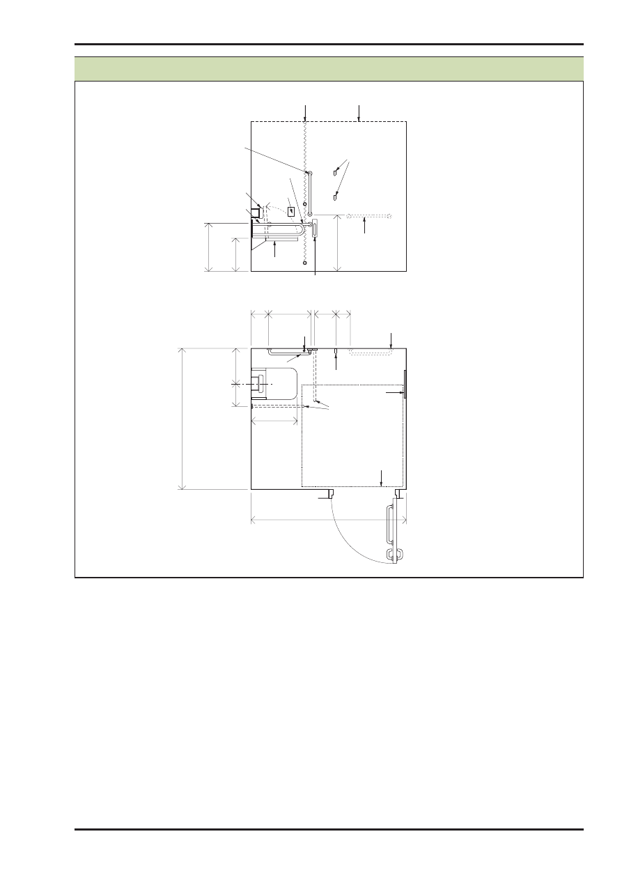
For shower facilities
k.
individual self-contained shower
facilities comply with Diagram 23;
l.
where showers are provided in
commercial developments for the
benefit of staff, at least one wheelchair-
accessible shower compartment
complying with Diagram 23 should be
provided;
m.
a shower curtain, which encloses
the seat and the rails when they are in
a horizontal position, can be operated
from the shower seat;
n.
a shelf that can be reached from
the shower seat or from the wheelchair,
before or after transfer, is provided for
toiletries;
o.
the floor of the shower and
shower area is slip resistant and self-
draining;
p.
a shower terminal fitting complies
with Guidance Note G18.5 of the
Guidance Document relating to
Schedule 2: Requirement for Water
Fittings, of the Water Supply (Water
Fittings) Regulations 1999, SI
1999/1148, and the markings on the
shower control are logical and clear;
Sanitary accommodation in buildings other than dwellings
Approved Document M
59
M1/M3
BUILDINGS OTHER THAN DWELLINGS
Alarm
pull cord
Possible location
of towel rail
Clothes hooks at
1400 and 1050
above floor level
Vertical grab rail
length 500 min.
2100 minimum unobstructed height
Back rest
Horizontal
grab rail
Alarm reset
Tip-up seat
Alarm pull cord
Elevation
Drop-down rail
on side wall
Drop-down rail
Drop-down rails
Possible location of towel rail
(or locate in self-contained
shower room)
Clothes hooks
1500 x 1500
Wheelchair turning space
Tip-up
seat
Grab rail
Mirror
Plan
480
680
800
2200
650
500
320
250
600
300
200
50
1200
2000
Diagram 22 An example of a self-contained changing room for individual use
q. where
wheelchair-accessible
shower facilities are available in
communal areas, shower controls are
positioned between 750 and 1000mm
above the floor;
For shower facilities incorporating a
WC
r.
the minimum overall dimensions
of, and the arrangement of fittings
within, an individual self-contained
shower area incorporating a corner
WC, e.g. in a sports building, comply
with Diagram 24;
s.
a choice of left-hand and right-
hand transfer layouts is available when
more than one shower area
incorporating a corner WC is provided.
Note: Guidance prepared by the Health
and Safety Executive on the slip
resistance of floor surfaces is given in
Annex C of BS 8300.
Wheelchair-accessible bathrooms
Design considerations
5.19 Wheelchair users and ambulant
disabled people should be able to
wash or bathe either independently or
with assistance from others. The
relationship of the bath to other
sanitary fittings, and to the space
Approved Document M
Sanitary accommodation in buildings other than dwellings
60
M1/M3
BUILDINGS OTHER THAN DWELLINGS
Range for adjustable
and detachable
shower head
Range for
shower controls
Tip-up seat
Drop-down rail
Drop-down rail
on side wall
Back rest
Fixed shower head
(Alarm pull cord,
horizontal and vertical grab rails,
shower curtain rail and towel rail
not shown for clarity)
Elevation
Floor drain
Alarm
pull cord
Shower control and
adjustable shower head
Additional, optional
tip-up seat for users
when drying
(mainly for ambulant users)
Towel rail
Drop-down rails
Fall of
floor
1500 x 1500
Wheelchair turning space
Shower curtain
Tip-up
seat
Clothes hooks
Plan
480
1400
1200
1000
750
680
500
2200
650
500
320
250
600
50
300
1200
2000
Diagram 23 An example of a self-contained shower room for individual use
required for manoeuvring, is therefore
critical. Providing a choice of bathroom
layout, wherever possible, will meet the
needs of many disabled people and
help maintain their independence.
5.20 The guidance covered here
applies to wheelchair-accessible
bathing facilities where provided in
buildings such as hotels, motels,
relatives’ accommodation in hospitals,
and to student accommodation and
sports facilities where baths are
provided as an alternative, or as a
supplement, to showers. For guidance
on the provision of en-suite bathrooms
associated with hotel bedrooms,
see 4.19.
Note: More detailed guidance on
appropriate sanitary and other fittings,
including facilities for the use of mobile
and fixed hoists is given in BS 8300.
Provisions
5.21 Wheelchair-accessible bathrooms
will satisfy Requirement M1 or M3 if:
a.
the minimum overall dimensions
of, and the arrangement of fittings
within, a bathroom for individual use
incorporating a corner WC comply with
Diagrams 25 and 26;
b.
a choice of layouts suitable for
left-hand and right-hand transfer is
provided when more than one
bathroom for individual use
incorporating a corner WC is available;
c.
the floor of a bathroom is slip
resistant when dry or when wet;
d.
the bath is provided with a
transfer seat, 400mm deep and equal
to the width of the bath;
Sanitary accommodation in buildings other than dwellings
Approved Document M
61
M1/M3
BUILDINGS OTHER THAN DWELLINGS
Floor drain
Fall of floor
The arrangement of shower controls
and ancillary fittings is as Diag 23
The arrangement of corner WC
and ancillary fittings is as Diag 18
The larger basin is set back
200mm to maintain the correct
relationship of its leading
edge with the WC
Tip-up
seat
Shower curtain
Wash basin
Drop-down rails
1500 x 1500
Wheelchair turning space
Alarm pull cord
Vertical grab rail
Towel rail
Mirror
Note
Layout shown for right hand transfer to shower seat and WC
140-160
500
300
2400
2500
Diagram 24 An example of a shower room incorporating a corner WC for individual
use
e.
doors are preferably outward-
opening and are fitted with a horizontal
closing bar fixed to the inside face;
f.
an emergency assistance pull-
cord complying with 4.30(e) is easily
identifiable and reachable from the
bath or from the floor;
g.
an emergency assistance alarm
system complying with 5.4(h) is
provided.
Note: Guidance prepared by the Health
and Safety Executive on the slip
resistance of floor surfaces is given in
Annex C of BS 8300.
Approved Document M
Sanitary accommodation in buildings other than dwellings
62
M1/M3
BUILDINGS OTHER THAN DWELLINGS
Two clothes hooks,
at 1400 and 1050
above the floor
1500 x 1500
Wheelchair turning space
Sanitary dispenser
Towel rail
Bath transfer
seat
Disposal bin
Shelf
The arrangement of the
corner WC and ancillary
fittings is as Diag 18
For the arrangement
of the bath and ancillary
fittings see Diag 26
Note
Layout shown for right hand transfer to bath and WC
140-160
2700
2500
Diagram 25 An example of a bathroom incorporating a corner WC
Sanitary accommodation in buildings other than dwellings
Approved Document M
63
M1/M3
BUILDINGS OTHER THAN DWELLINGS
50 to 60 clearance
between wall
and handrail
Proprietary transfer seat
supported on bath rim
Mixer tap
Purpose made transfer
seat at head of bath
Gap where necessary to
allow for the use of a
mobile hoist
Vertical grab rail
(500 min. length)
Horizontal
grab rail
Alternatively rail partially cranked
at max. 13° to horizontal
*
To meet both these criteria,
a shallower than normal
bath may be needed
200
400 min.
depth
250
150min.
*
75 to 100
480
*
600
200
Gap clear of bath supports
Bath length
Alarm pull cord
Alarm
pull cord
Diagram 26 Grab rails and fittings associated with a bath

MEANS OF ACCESS TO AND
INTO THE DWELLING
Objective
6.1
The objective is to make
reasonable provision within the
boundary of the plot of the dwelling for
a disabled person to approach and
gain access into the dwelling from the
point of alighting from a vehicle which
may be within or outside the plot. In
most circumstances it should be
possible to provide a level or ramped
approach.
6.2
On plots which are reasonably
level, wheelchair users should normally
be able to approach the principal
entrance. Exceptionally, for more
steeply sloping plots, it is considered
reasonable to provide for stick or
crutch users (see paragraph 6.9)
6.3
On plots where wheelchair users
have approached the entrance, they
should also be able to gain access into
the dwelling-house and entrance level
flats.
Approach to the dwelling
Design considerations
6.4
The provision of an approach
which can be used by disabled people,
including wheelchair users, will often
be a matter of practicability. Variations
in topography, available plot area, or
the distance of the dwelling from the
point of access, may all influence the
type of approach that can be provided.
6.5
Normally, the provisions will apply
to the approach to the principal
entrance. However, if that is not
possible in a particular situation, it
would be reasonable to apply them to
the approach to a suitable alternative
entrance.
6.6
The approach should be as safe
and as convenient for disabled people
as is reasonable and, ideally, be level
or ramped. However, on steeply sloping
plots a stepped approach would be
reasonable.
6.7
If a stepped approach to the
dwelling is unavoidable, the aim should
be for the steps to be designed to suit
the needs of ambulant disabled people
(see paragraph 6.17).
6.8
Alternatively, the presence of a
driveway might provide a better
opportunity for creating a level or
ramped approach, particularly if it also
provides the sole means of approach
for visitors who are disabled. The
driveway itself could be designed as
the approach from the pavement or
footpath or may be the place where
visitors park. In such cases, a level or
ramped approach may be possible
from the car parking space, particularly
on steeply sloping plots.
6.9
It is important that the surface of
an approach available to a wheelchair
user should be firm enough to support
the weight of the user and his or her
wheelchair and smooth enough to
permit easy manoeuvre. It should also
take account of the needs of stick and
crutch users. Loose laid materials,
such as gravel and shingle, are
unsuitable for the approach.
6.10 The width of the approach,
excluding space for parked vehicle,
should take account of the needs of a
wheelchair user, or a stick or crutch
user (see paragraph 6.13).
Note: Account will also need to be
taken of planning requirements, such
as for new building within conservation
areas. Location and arrangement of
dwellings on the site is a matter for
planning, whereas the internal layout
and construction of the dwellings is a
matter for building control.
Provisions
6.11 Requirement M1 will be satisfied,
if, within the plot of the dwelling, a
suitable approach is provided from the
point of access to the entrance. The
point of access should be reasonably
level and the approach should not have
crossfalls greater than 1 in 40.
Approved Document M
64
Section 6
Means of access to and into the dwelling
M1
DWELLINGS
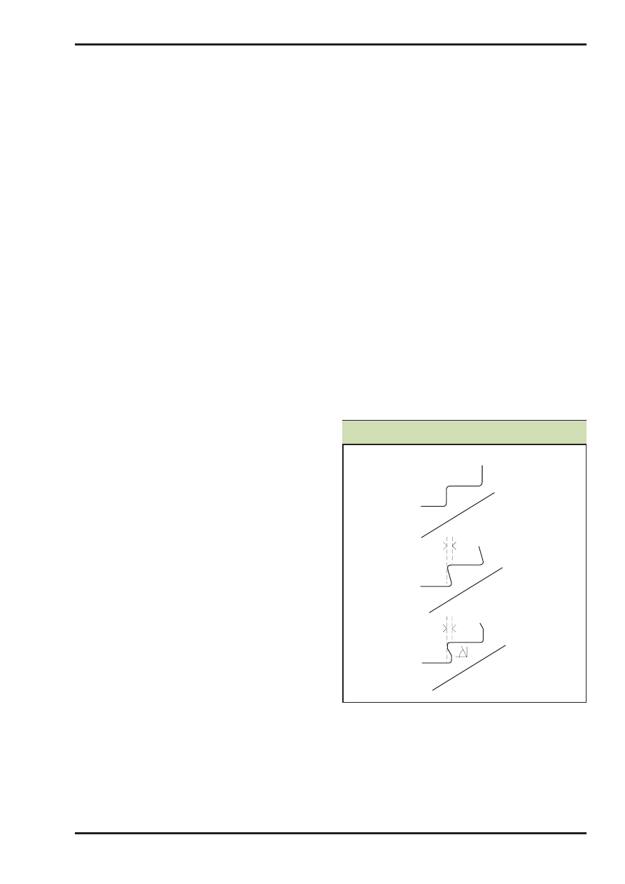
6.12 The whole, or part, of the
approach may be a driveway.
Level approach
6.13 A ‘level’ approach will satisfy
Requirement M1 if its gradient is not
steeper than 1 in 20, its surface is firm
and even and its width is not less than
900mm.
Ramped approach
6.14 If the topography is such that the
route from the point of access towards
the entrance has a plot gradient
exceeding 1 in 20 but not exceeding 1
in 15, Requirement M1 will be satisfied
if a ramped approach is provided.
6.15 A ramped approach will satisfy
Requirement M1 if it:
a.
has a surface which is firm and
even;
b.
has flights whose unobstructed
widths are at least 900mm;
c.
has individual flights not longer
than 10m for gradients not steeper than
1 in 15, or 5m for gradients not steeper
than 1 in 12; and
d.
has top and bottom landings and,
if necessary, intermediate landings,
each of whose lengths is not less than
1.2m, exclusive of the swing of any
door or gate which opens onto it.
Stepped approach
6.16 If the topography is such that the
route (see paragraphs 6.6 - 6.8) from
the point of access to the entrance has
a plot gradient exceeding 1 in 15,
Requirement M1 will be satisfied if a
stepped approach is provided.
6.17 A stepped approach will satisfy
Requirement M1 if:
a.
it has flights whose unobstructed
widths are at least 900mm;
b.
the rise of a flight between
landings is not more than 1.8m;
c.
it has top and bottom and, if
necessary, intermediate landings, each
of whose lengths is not less than
900mm;
d.
it has steps with suitable tread
nosing profiles (see Diagram 27) and
the rise of each step is uniform and is
between 75mm and 150mm;
e.
the going of each step is not less
than 280mm, which for tapered treads
should be measured at a point 270mm
from the ‘inside’ of the tread; and
f.
where the flight comprises three
or more risers, there is a suitable
continuous handrail on one side of the
flight. A suitable handrail should have a
grippable profile; be between 850mm
and 1000mm above the pitch line of
the flight; and extend 300mm beyond
the top and bottom nosings.
Approach using a driveway
6.18 Where a driveway provides a
means of approach towards the
entrance, it will satisfy Requirement M1
if the driveway provides an approach
past any parked cars in accordance
with paragraphs 6.11 - 6.27, above.
Access into the dwelling
Design considerations
6.19 Where the approach to the
entrance consists of a level or ramped
approach (see paragraphs 6.13 - 6.15),
Approved Document M
65
M1
Means of access to and into the dwelling
DWELLINGS
15-25mm
15-25mm
60º min
See para 6.17
Diagram 27 External step profiles

an accessible threshold at the entrance
should be provided. An accessible
threshold into entrance level flats
should also be provided.
6.20 In exceptional circumstances
where the approach to the entrance
consists of a stepped approach (see
paragraph 6.16), it would still be
reasonable to provide an accessible
threshold. If a step into the dwelling is
unavoidable, the rise should be no
more than 150mm.
Provisions
6.21 If the approach to the dwelling or
block of flats consists of a level or
ramped approach, Requirement M1 will
be satisfied if an accessible threshold
is provided into the entrance. The
design of an accessible threshold
should also satisfy the requirements of
Part C2: ‘Dangerous and offensive
substances’ and Part C4: ‘Resistance
to weather and ground moisture’.
Note: General guidance on design
considerations for accessible
thresholds has been published
separately by The Stationery Office as
‘Accessible thresholds in new housing:
guidance for house builders and
designers’.
Entrance doors
Design considerations
6.22 The provision of an appropriate
door opening width will enable a
wheelchair user to manoeuvre into the
dwelling.
Provisions
6.23 Requirement M1 will be satisfied
if an external door providing access for
disabled people has a minimum clear
opening width of 775mm.
Note: For dwellings, the clear opening
width is taken from the face of the door
stop on the latch side to the face of the
door when open at 90˚ (i.e. no change
from the 1999 edition of AD M).
Approved Document M
Means of access to and into the dwelling
66
M1
DWELLINGS
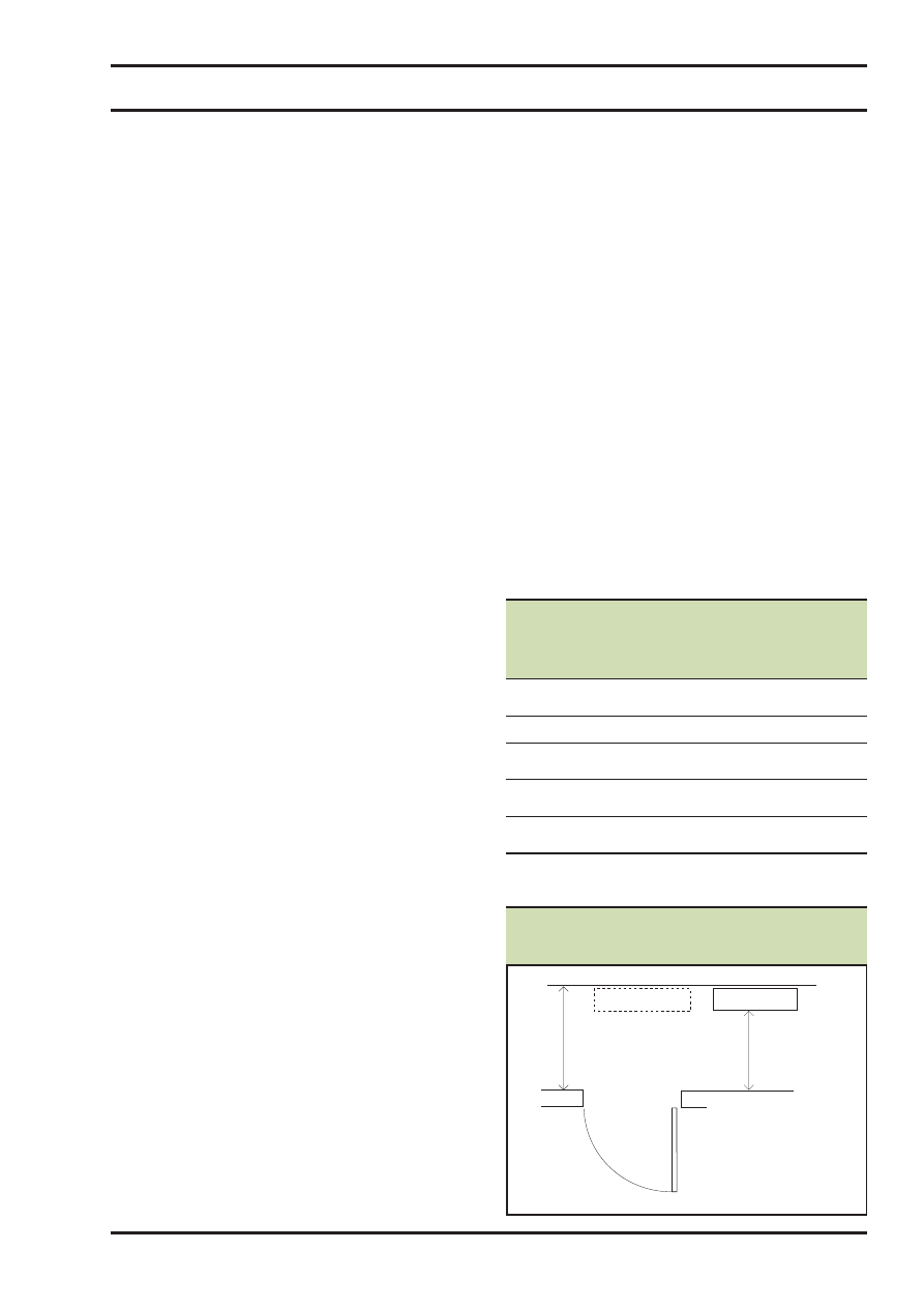
CIRCULATION WITHIN THE
ENTRANCE STOREY OF THE
DWELLING
Objective
7.1
The objective is to facilitate
access within the entrance storey or
the principal storey of the dwelling, into
habitable rooms and a room containing
a WC, which may be a bathroom on
that level.
Corridors, passageways and
internal doors within the entrance
storey
Design considerations
7.2
Corridors and passageways in the
entrance storey should be sufficiently
wide to allow convenient circulation by
a wheelchair user. Consideration
should be given to the effects of local
obstruction by radiators and other
fixtures.
7.3
It will be necessary to consider
the layout of a room served by an
alternative to the principal entrance in
order that a wheelchair user can pass
through it to reach the remainder of the
entrance storey.
7.4
Internal doors need to be of a
suitable width to facilitate wheelchair
manoeuvre. A wider door than generally
provided would allow easier
manoeuvring when it is necessary for a
wheelchair user to turn into a door
opening, as opposed to approaching it
head-on.
Provisions
7.5
Requirement M1 will be satisfied
if:
a.
a corridor or other access route in
the entrance storey or principal storey
serving habitable rooms and a room
containing a WC (which may be a
bathroom) on that level, has an
unobstructed width in accordance with
Table 4;
b.
a short length (no more than 2m)
of local permanent obstruction in a
corridor, such as a radiator, would be
acceptable provided that the
unobstructed width of the corridor is
not less than 750mm for that length,
and the local permanent obstruction is
not placed opposite a door to a room if
it would prevent a wheelchair user
turning into or out of the room; and
c.
doors to habitable rooms and a
room containing a WC have minimum
clear opening widths shown in Table 4,
when accessed by corridors or
passageways whose widths are in
accordance with those listed in Table 4.
Table 4 shows the minimum widths of
corridors and passageways that would
be necessary to enable wheelchair
users to turn into and out of a range of
doorway widths.
Section 7
Circulation within the entrance storey of the dwelling
Approved Document M
67
M1
DWELLINGS
Table 4 Minimum widths of corridors
and passageways for a range of
doorway widths
Doorway clear opening
Corridor/passageway
width (mm)
width (mm)
750 or wider
900 (when approach head-on)
750
1200 (when approach not
head-on)
775
1050 (when approach not
head-on)
800
900 (when approach not
head-on)
750mm min
width with
short obstruction
900mm min
corridor width
No obstruction here
See para 7.5
Diagram 28 Corridors, passages and
internal doors
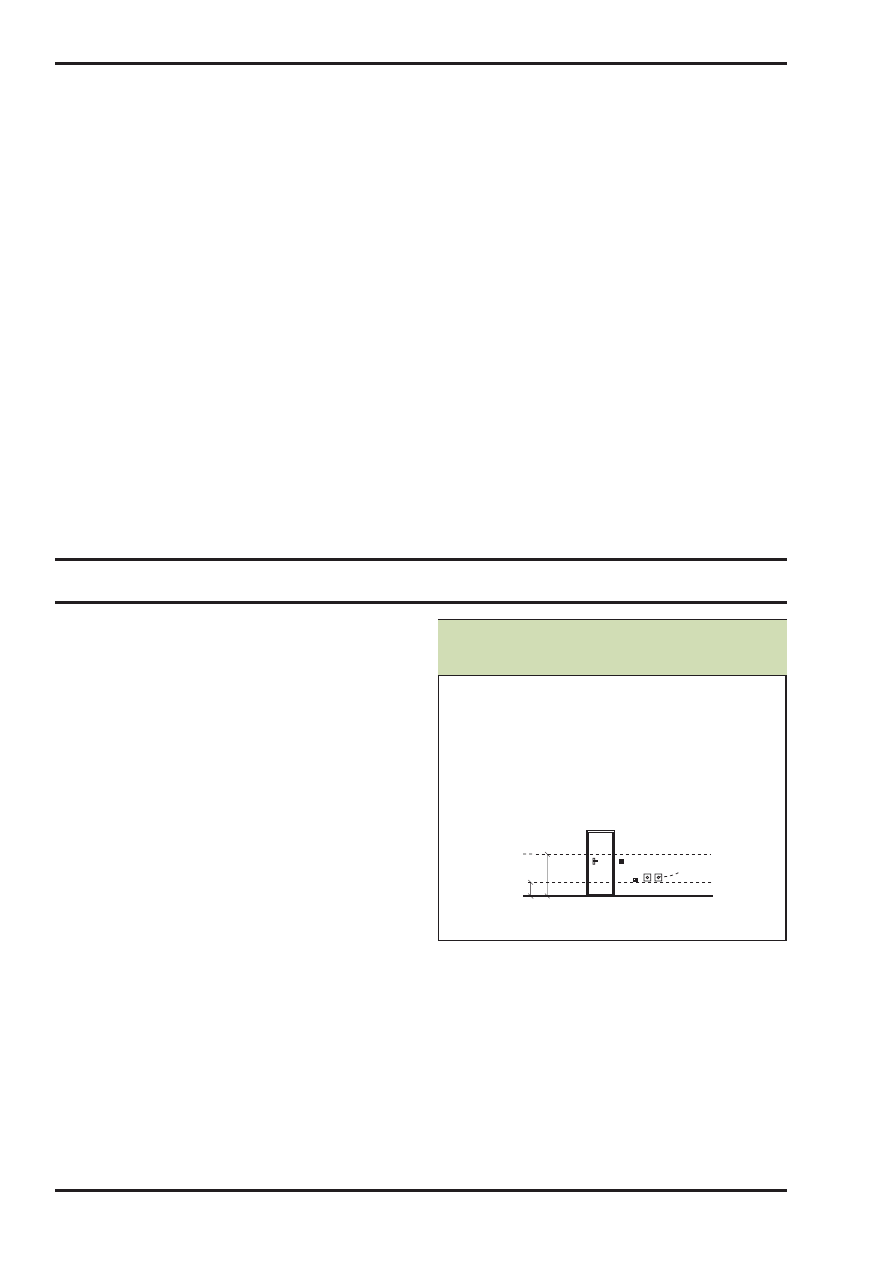
Vertical circulation within the
entrance storey
Design considerations
7.6
In exceptional circumstances,
where severely sloping plots are
involved, a stepped change of level
within the entrance storey may be
unavoidable. In those instances, the
aim should be to provide a stair of
reasonable width for ambulant disabled
people to negotiate the steps with
assistance and for handrails on both
sides. Approved Document K of the
Building Regulations contains guidance
on the design of private stairs in
dwellings.
Provisions
7.7
A stair providing vertical
circulation within the entrance storey of
the dwelling will satisfy Requirement
M1 if:
a.
it has flights whose clear widths
are at least 900mm;
b.
there is a suitable continuous
handrail on each side of the flight and
any intermediate landings where the
rise of the flight comprises three or
more rises; and
c.
the rise and going are in
accordance with the guidance in
Approved Document K for private
stairs.
Approved Document M
Circulation within the entrance storey of the dwelling
68
M1
DWELLINGS
ACCESSIBLE SWITCHES AND
SOCKET OUTLETS IN THE
DWELLING
Objective
8.1
The aim is to assist those people
whose reach is limited to use the
dwelling more easily by locating wall-
mounted switches and socket outlets
at suitable heights.
Design considerations
8.2
Switches and socket outlets for
lighting and other equipment should be
located so that they are easily
reachable.
Provisions
8.3
A way of satisfying Requirement
M1 would be to provide switches and
socket outlets for lighting and other
equipment in habitable rooms at
appropriate heights between 450mm
and 1200mm from finished floor level
(see Diagram 29).
Section 8
sw
itches
tv soc
k
e
ts
soc
k
ets
telephone jac
k
points
1200mm
450mm
door bells
,
entr
y
phones
see para 8.3
Diagram 29 Heights of switches,
sockets etc
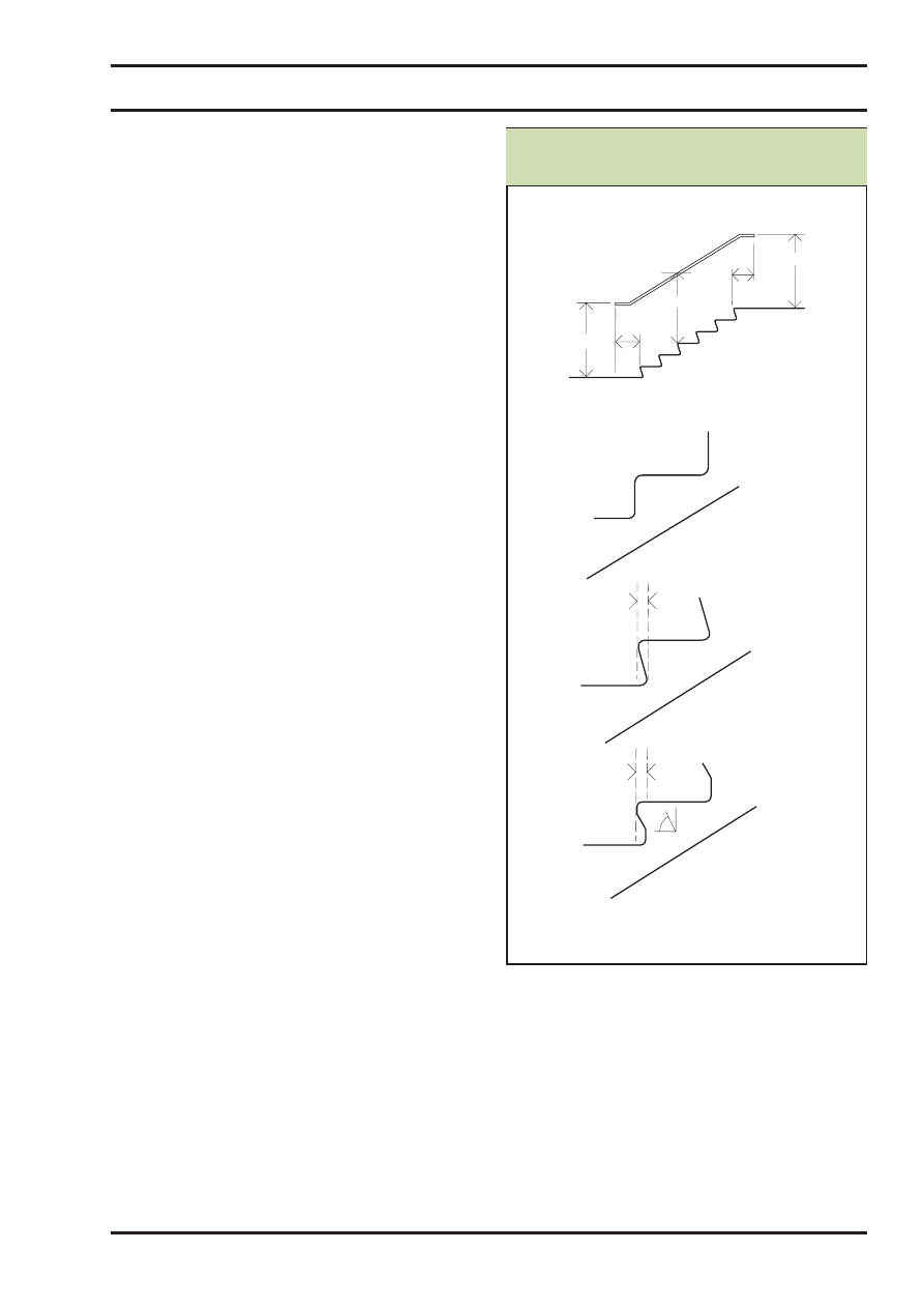
PASSENGER LIFTS AND
COMMON STAIRS IN BLOCKS OF
FLATS
Objectives
9.1
For buildings containing flats, the
objective should be to make
reasonable provision for disabled
people to visit occupants who live on
any storey.
9.2
The most suitable means of
access for disabled people from one
storey to another is a passenger lift.
However, a lift may not always be
provided.
Design considerations
9.3
If there is no passenger lift
providing access between storeys, a
stair should be designed to suit the
needs of ambulant disabled people. In
any event, a stair in a common area
should be designed to be suitable for
people with impaired sight.
9.4
Where a lift is provided, it should
be suitable for an unaccompanied
wheelchair user. Suitable provision
should also be made for people with
sensory impairments. Measures should
also be adopted which give a disabled
person sufficient time to enter the lift to
reduce the risk of contact with closing
doors.
Provisions
Common stairs
9.5
Requirement M1 will be satisfied
if a building containing flats, in which a
passenger lift is not to be installed, is
provided with a suitable stair, which
has:
a.
all step nosings distinguishable
through contrasting brightness;
b.
top and bottom landings whose
lengths are in accordance with Part K1;
c.
steps with suitable tread nosing
profiles (see Diagram 30) and uniform
rise of each step, which is not more
than 170mm;
d.
uniform going of each step, which
is not less than 250mm, which for
tapered treads should be measured at
a point 270mm from the inside of the
tread;
e.
risers which are not open; and
f.
a suitable continuous handrail on
each side of flights and landings if the
rise of the stair comprises two or more
rises.
Section 9
Passenger lifts and common stairs in blocks of flats
Approved Document M
69
M1
DWELLINGS
15-25mm
15-25mm
1000mm
A. COMMON STAIRS AND HANDRAILS
B. EXAMPLES OF SUITABLE TREAD NOSING PROFILES
Maximum rise 170mm
Maximum going 250mm
1000mm
900mm
300mm
300mm
60º min
see para 9.5
Diagram 30 Common stairs in blocks of
flats

Lifts
9.6
Requirement M1 will be satisfied
if a building, or a part of a building
which contains flats above the entrance
storey and in which passenger lift
access is to be installed, is provided
with a suitable passenger lift with a
minimum load capacity of 400kg.
9.7
One way of satisfying
Requirement M1 would be to provide a
passenger lift which:
a.
has a clear landing at least
1500mm wide and at least 1500mm
long in front of its entrance;
b.
has a door or doors which provide
a clear opening width of at least
800mm;
c.
has a car whose width is at least
900mm and whose length is at least
1250mm (other dimensions may satisfy
Requirement M1 where shown by test
evidence or experience in use, or
otherwise, to be suitable for an
unaccompanied wheelchair user);
d.
has landing and car controls
which are not less than 900mm and not
more than 1200mm above the landing
and the car floor, at a distance of at
least 400mm from the front wall;
e.
is accompanied by suitable tactile
indication on the landing and adjacent
to the lift call button to identify the
storey in question;
f.
has suitable tactile indication on
or adjacent to lift buttons within the car
to confirm the floor selected;
g
incorporates a signalling system
which gives visual notification that the
lift is answering a landing call and a
‘dwell time’ of five seconds before its
doors begin to close after they are fully
open: the system may be overridden by
a door re-activating device which relies
on appropriate electronic methods, but
not a door edge pressure system,
provided that the minimum time for a
lift door to remain fully open is 3
seconds; and
h.
when the lift serves more than 3
storeys, incorporates visual and audible
indication of the floor reached.
Approved Document M
70
Passenger lifts and common stairs in blocks of flats
M1
DWELLINGS
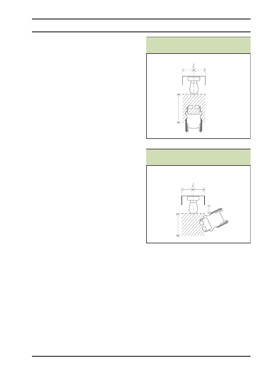
WC PROVISION IN THE ENTRANCE
STOREY OF THE DWELLING
Objectives
10.1 The primary objective is to
provide a WC in the entrance storey of
the dwelling and to locate it so that
there should be no need to negotiate a
stair to reach it from the habitable
rooms in that storey. Where the
entrance storey contains no habitable
rooms, it is reasonable to provide a WC
in either the entrance storey or the
principal storey.
Design considerations
10.2 The aim is to provide a WC within
the entrance storey or the principal
storey of a dwelling. Where there is a
bathroom in that storey, the WC may
be located in that bathroom. It will not
always be practical for the wheelchair
to be fully accommodated within the
WC compartment.
Provision
10.3 Requirement M4 will be satisfied,
if:
a.
a WC is provided in the entrance
storey of a dwelling which contains a
habitable room; or where the dwelling
is such that there are no habitable
rooms in the entrance storey, if a WC is
provided in either the entrance storey
or the principal storey;
b.
the door to the WC compartment
opens outwards, and is positioned to
enable wheelchair users to access the
WC and has a clear opening width in
accordance with Table 4 (door
openings wider than the minimum in
Table 4 allow easier manoeuvring and
access to the WC by wheelchair users);
and
c.
the WC compartment provides a
clear space for wheelchair users to
access the WC (see Diagrams 31 & 32)
and the washbasin is positioned so that
it does not impede access.
Section 10
WC provision in the entrance storey of the dwelling
Approved Document M
71
M1/M4
DWELLINGS
750mm
min
To enable transfer,
the wheelchair
should be able to
approach within
400mm of the
front of the WC
500mm*
500mm*
C
see para 10.3
*500mm preferred
(450mm min)
Diagram 31 Clear space for frontal
access to WC
750mm
edge of door opening
400mm
500mm (450mm min)
C
see para 10.3
250mm
Diagram 32 Clear space for oblique
access to WC

Approved Document M
72
M
A
Access - definition
0.29
Access into buildings
2.1-2.29,
6.19-6.23
Access routes to buildings see
Approaches
Access routes within buildings
0.5, 0.11, 3.14
Access Statements
0.20-0.28
Accessible - definition
0.29
Accessible entrances
1.6,
2.1-2.7
Acoustic design
3.13
Alterations see Material
alterations
Application of Part M
0.1-0.13
Approaches - dwellings
6.1-6.18
Approaches - hazards
1.5,
1.38-1.39
Approaches - level (non-domestic)
1.6-1.13
Approaches - lighting
1.11, 1.13
Approaches - objectives
1.1-1.5
Approaches - ramps
1.8, 1.19-
1.26, 6.1, 6.14-6.15
Approaches - steps
1.21,
1.27-1.37, 6.6-6.7, 6.16-6.17,
6.20
Approaches - surfaces
1.13, 6.9
Approaches - widths
1.2, 1.10-
1.11, 1.13, 6.10, 6.15, 6.17
Artificial lighting see Lighting
Assistance dogs
2.20, 4.6
Audible emergency assistance call
signals
4.24, 5.4
Audible information - lifting
devices
3.31, 3.34, 3.37,
3.43, 9.7
Audible signs
4.35 note
Audible warnings - doors
2.21
Audience seating
4.2, 4.5-4.8,
4.12
Audience seating - legroom
4.7
Audience seating - sight lines
4.9
Audience seating - wheelchair
spaces
4.6-4.7, 4.10-4.12
B
Baby changing facilities
5.5-5.6,
5.12
Balconies 4.19,
4.24
Bars - refreshment facilities
4.3,
4.13-4.16
Bathrooms see Sanitary
accommodation
Bedrooms 4.4,
4.17-4.24
Bedrooms - balconies
4.19, 4.24
Bedrooms - doors
3.10,
4.22-4.24
Bedrooms - en suite bedrooms
4.19, 4.24
Bedrooms - hotels and motels
4.17-4.24
Bedrooms - wardrobes
4.20
Bedrooms - wheelchair accessible
4.17-4.24
Bedrooms - window controls
4.24
Blocks of flats
9.1-9.7
BS EN 81-70
3.34
BS EN 81 series
3.43, 3.49
BS 3402
5.10, 5.14
BS 5503 Part 3
5.9-5.10, 5.14
BS 5504 Part 4
5.9 -5.10, 5.14
BS 5588 Part 8
3.34, 3.51
BS 8300
0.9, 3.5 note, 3.9 note,
3.27 note, 4.35 note, 5.17
note, 5.18 note, 5.21 note
C
CADW - Welsh Historic
Monuments Executive Agency
0.18
Car parking
0.5, 0.9, 1.14-1.18
Change of use
0.10-0.12
Ceilings - surface materials
4.32
Changing rooms see Sports
Facilities
Cinemas
4.10, 4.12
Clothes shops - changing
facilities
5.17
Colour contrast see Visual
contrast
Communication aids
0.14, 3.6,
4.31-4.36
Conference facilities
4.1, 4.5,
4.9, 4.36
Connecting doors
4.22
Controls
4.25-4.30
Controls - height
4.25, 4.30,
5.18
Controls - lifting devices
3.27-3.28, 3.43, 3.49, 9.7
Controls - lighting
4.30, 5.4
Controls - powered doors
2.21
Controls - showers
5.18
Controls - windows
4.24
Corridors
3.11-3.14, 7.2-7.5
Counters - reception desks
3.3,
3.6
Counters - refreshment facilities
4.3, 4.16
Curtain opening devices
4.20
D
Definitions
0.23-0.24
Department for Transport
1.5
Dimensions - doors
2.13, 3.10,
6.22-6.23
Dimensions - entrance lobbies
2.27, 2.29
Dimensions - internal lobbies
3.16
Dimensions - lifting devices
3.34, 3.43, 3.49, 9.7
Dimensions - parking bays
1.18
Dimensions - wheelchair-
accessible bedrooms
4.24
Disability Discrimination Act 1995
0.1, 0.9, 0.22
District Surveyors Association
4.10
Door furniture
2.13, 2.16-2.17,
3.10, 4.24, 5.4
Door mats
2.7
Doors see also Entrance doors
Doors - audible warnings
2.21
Doors - bathrooms
5.21
Doors - card-activated locks
4.23
Doors - connecting hotel
bedrooms
4.22
Doors - controls
2.21, 4.23
Doors - dimensions
2.13, 3.10,
6.22-6.23
Doors - electrically powered hold-
open devices
3.7, 3.9 note,
3.10
Doors - entry systems
2.7
Doors - fire doors
3.10
Doors - glass doors
2.22, 2.24,
3.10
Doors - handles
4.24, 5.4
Doors - internal
3.7-3.10,
7.4-7.5
Doors - lifting platforms
3.41,
3.43
Doors - low energy powered door
systems
3.7, 3.9 note, 3.10
Doors - manually operated
2.9,
2.14-2.17, 3.9
Doors - opening force
2.13,
3.10, 5.4
Doors - passenger lifts
3.30,
3.33-3.34
Doors - powered
2.10, 2.13,
2.18-2.21, 3.10, 4.18
Doors - privacy bolts
5.4
Doors - revolving
2.20
Doors - safety stops
2.21
Doors - self-closing devices
2.14, 2.26, 3.7
Doors - sliding doors
4.24
Index
Index to sections 0 to 10
M
INDEX TO SECTIONS 0 TO 10

Approved Document M
73
M
Doors - swing
2.21, 2.29, 4.24
Doors - swing-free closing
devices
3.7, 3.9 note, 3.10
Doors - swings
5.14
Doors - toilets
3.14, 5.10,
5.14,10.3
Doors - vision panels
2.13, 3.10
Doors - visual contrast
3.8, 3.10
Doors - visual warnings
2.21
Doors - wardrobes
4.24
Doors - wheelchair accessible
bathrooms
5.21
Doors - wide angle viewers
4.24
Drop down rails
5.8, 5.10
Driveways
6.8, 6.12, 6.18
E
Electric card activated locks
4.23
Electrically powered hold-open
devices
3.7, 3.9 note, 3.10
Embossed room numbers
4.24
Emergency assistance alarms see
also Fire alarms
4.24, 4.30,
5.4, 5.10, 5.18, 5.21
Emergency assistance call signals
4.24, 5.10
Emergency assistance pull cords
4.30, 5.10, 5.18, 5.21
Emergency communication
systems - lifting devices
3.28
Emergency escape routes
5.4
Emergency evacuation -
passenger lifts
3.34
En suite facilities - hotel rooms
4.19, 4.24
English Heritage
0.18
Enquiry desks see also Reception
desks
4.32
Entertainment facilities see also
Cinemas, Theatres
4.1, 4.5,
4.10, 4.12, 4.36
Entrance doors see also Doors,
Principal entrance
2.8-2.24
Entrance doors - audible warnings
2.21
Entrance doors - card swipes
2.21
Entrance doors - coded entry
2.21
Entrance doors - dimensions
2.13, 6.22-6.23
Entrance doors - door furniture
2.16-2.17
Entrance doors - dwellings
6.22-
6.23
Entrance doors - glass
2.22-2.24
Entrance doors - glass -
manifestation
2.22, 2.24
Entrance doors - manually
operated
2.9, 2.14-2.17
Entrance doors - powered
2.10,
2.13, 2.18-2.21
Entrance doors - powered -
manual controls
2.21
Entrance doors - safety stops
2.21
Entrance doors - self-closing
devices
2.14, 2.26
Entrance doors - swing doors
2.29
Entrance doors - thresholds
(dwellings)
6.19-6.21
Entrance doors - thresholds (non-
domestic)
2.6-2.7
Entrance doors - vision panels
2.13
Entrance doors - visual warnings
2.21
Entrance doors - weather
protection
2.6-2.7
Entrance doors - width (dwellings)
6.22-6.23
Entrance doors - width (non-
domestic)
2.11, 2.13
Entrance halls
3.2
Entrance lobbies
2.25-2.29
Entrance lobbies - dimensions
2.27, 2.29
Entrance storey - changes in level
7.6-7.7
Entrance storey - dwellings
7.1-
7.7, 10.1-10.3
Entrance storey - steps
7.6-7.7
Entrance storey - WC provision
10.1-10.3
Entrances
0.15
Escape routes - internal corridors
3.14
Extensions - dwellings
0.2-0.4
Extensions - non domestic
buildings
0.5-0.8
F
Finger rinse basins see Sanitary
accommodation
Fire alarms see also Emergency
assistance alarms
3.10, 4.24,
5.4
Fire doors see Doors
Flats
9.1-9.7
Floor levels - refreshment facilities
4.15
Floor surfaces see also Surfaces
2.7, 2.29, 3.6, 3.14, 3.16, 5.18,
5.21
Floor surfaces - materials
4.32
Floor surfaces - reception areas
3.6
Floor surfaces - slip resistant
3.6, 3.14, 5.18, 5.21
Floors see Storeys
Football Stadia Improvement Fund
4.11
G
Glass doors see Doors
Glazed screens
2.22, 2.24, 3.4,
3.14
Goings - steps and stairs
(domestic)
6.17, 9.5
Goings - steps and stairs (non-
domestic)
1.33, 3.51
Grab bars see Sanitary
accommodation
Grab rails see Sanitary
accommodation
Gradients - approaches
(dwellings)
6.11, 6.13
Gradients - approaches (non-
domestic)
1.7-1.8, 1.13,
1.19-1.20, 1.26
Gradients - internal ramps (non-
domestic)
3.53
Guard rails - hazards in lobbies
3.16
H
Habitable rooms - definition
0.30
Halls of residence
0.16
Handrails - audience seating
4.12
Handrails - dwellings
6.17,
7.6-7.7, 9.5
Handrails - non-domestic
1.26,
1.32, 1.34-1.37, 3.54-3.55
Hazards - approach routes
1.5,
1.38-1.39
Hazards - corridors
3.14
Hazards - internal lobbies
3.16
Hazards - warning surfaces
1.13, 1.33, 3.50
Hearing enhancement systems
see Communication aids
Heat emitters
5.4, 5.10
Historic buildings
0.17-0.19,
3.22
Hoists - bathrooms
5.20 note
Horizontal circulation
3.1-3.16
Hot surfaces
5.3
Hotel bedrooms see Bedrooms
I
Induction loops see
Communication aids
Inductive couplers see
Communication aids
Infrared signals see
Communication aids
International Symbol of Access
2.7
Index to sections 0 to 10
INDEX TO SECTIONS 0 TO 10

Approved Document M
74
M
J
Joysticks - wheelchair platform
stairlifts
3.47
L
Lavatories see Sanitary
accommodation
Lecture facilities
4.1, 4.5, 4.9,
4.32, 4.36
Leisure facilities
4.1, 4.10, 4.36
Level approaches see Approaches
- level
Lifting devices
3.17-3.49
Lifting devices - accessibility to
toilets
5.10
Lifting devices - blocks of flats
9.6-9.7
Lifting devices - call buttons
3.34, 3.43, 9.7
Lifting devices - dimensions
3.34, 3.43, 3.49, 9.7
Lifting devices - illumination
3.26
Lifting devices - instructions for
use
3.43
Lifting devices - lifting platforms
3.22, 3.24, 3.35-3.43
Lifting devices - mirrors
3.34
Lifting devices - passenger lifts
3.17, 3.21-3.24, 3.29-3.34, 9.2,
9.6-9.7
Lifting devices - podiums and
stages
4.12
Lifting devices - speeds
3.43,
3.49
Lifting devices - visual contrast
3.18, 3.28, 3.34, 3.43
Lifting devices - visual information
3.31, 3.34, 3.37, 3.43
Lifting devices - wall surfaces
3.32, 3.42
Lifting devices - wheelchair
platform stairlifts
3.23-3.24,
3.44-3.49
Lifting platforms see Lifting
devices
Lifts see Lifting devices
Light switches
4.28-4.30, 5.3
Lighting
4.9, 4.34, 4.36
Lighting - artificial
4.34, 4.36
Lighting - conference facilities
4.9
Lighting - controls
4.30, 5.4
Lighting - lifting devices
3.26
Lighting - sanitary facilities
5.4
Lighting - uplighters
4.34
Limb storage facilities
5.18
Lip reading and speaking
3.4,
4.6, 4.9, 4.32, 4.34
Lobbies
2.25-2.29, 3.15-3.16
Lockers
3.14 note, 5.18
M
Maisonettes - definition
0.30
Manifestation - glass doors and
screens
2.22, 2.24, 3.14
Material alterations
0.1-0.4, 0.9
Mirrors in passenger lifts see
Lifting devices
Mixed use development
0.12
Mixer taps see Sanitary
accommodation
5.4
Motel bedrooms see Bedrooms
Motion sensors
2.18, 2.21
N
Notice boards
3.5
O
Opening force of doors See Doors
P
Parking 1.15-1.18
Parking ticket machines
1.16,
1.18
Passageways see Corridors
Passenger lifts see Lifting devices
Planning system
0.21
Platform lifts see Lifting devices -
lifting platforms
Plot gradient
6.14, 6.16
Plot gradient - definition
0.30
Plots - dwellings
6.1-6.3
Podiums see also Rostrums,
Stages
4.12
Point of access - definition
0.30
Principal entrance (dwellings)
6.2, 6.5, 7.3
Principal entrance (non-domestic)
0.29, 1.17-1.18, 3.6
Principal storey - definition
0.14,
0.30
Principal storey - dwellings
7.1,
7.5, 10.1-10.3
Principal storey - toilet provision
(dwellings)
10.1-10.3
Pull cords
4.20, 4.30, 5.3, 5.10
Public address systems see
Communication aids
Public telephones
4.14
Push buttons - doors
2.18, 2.21
Push buttons - lifting platforms
3.39
Push buttons - switches and
socket outlets
4.30
Push pads
2.21, 4.28-4.30, 5.3
R
Radio signals see Communication
aids
Ramps - approach routes
(dwellings)
6.14-6.15
Ramps - approach routes (non-
domestic)
1.19-1.26
Ramps - corridors
3.14
Ramps - handrails
1.26,
1.34-1.37
Ramps - internal (non-domestic)
3.14, 3.20, 3.52-3.53
Ramps - podiums and stages
4.12
Reception desks see also Enquiry
desks
3.2-3.6, 4.32
Reflective wall surfaces see Wall
surfaces
Refreshment facilities
4.13-4.16
Remote controls
2.21
Restaurants
4.13-4.16
Revolving doors see Doors
Risers - steps and stairs
(dwellings)
6.17, 9.5
Risers - steps and stairs (non-
domestic)
1.33, 3.51
Room numbers - embossed
4.24
Rostrums see also Podiums,
Stages
4.12
S
Sales counters
3.3
Sanitary accommodation
0.8,
0.14, 4.19, 4.24, 5.1-5.21,
10.1-10.3
Sanitary accommodation -
bathrooms
4.19, 4.24, 5.19-
5.21, 10.2
Sanitary accommodation -
changing rooms
5.15-5.18
Sanitary accommodation - cubicle
doors
5.3, 5.4, 10.3
Sanitary accommodation -
dimensions
5.7, 5.10, 10.3
Sanitary accommodation -
dwellings
10.1-10.3
Sanitary accommodation - en-
suite hotel rooms
4.19, 4.24
Sanitary accommodation -
enlarged cubicles
5.6, 5.12,
5.14
Sanitary accommodation -
entrance storey of dwellings
10.1-10.3
Sanitary accommodation - finger
rinse basins
5.8
Sanitary accommodation - grab
bars
5.4, 5.14
Sanitary accommodation - grab
rails
5.8, 5.10, 5.11, 5.18
Sanitary accommodation - hoists
5.20 note
Index to sections 0 to 10
INDEX TO SECTIONS 0 TO 10

Approved Document M
75
M
Sanitary accommodation - inward
opening doors
5.3, 5.14
Sanitary accommodation - lever
taps
4.23
Sanitary accommodation - mixer
taps
5.4
Sanitary accommodation -
outward opening doors
5.3,
5.14, 10.3
Sanitary accommodation -
provision
0.14, 5.2, 5.5-5.7,
5.13, 10.1-10.2
Sanitary accommodation -
refreshment facilities
4.14,
4.17
Sanitary accommodation -
separate sex washrooms
5.11-5.14
Sanitary accommodation -
showers
4.19, 4.24,
5.15-5.18
Sanitary accommodation - taps
4.23, 5.3-5.4
Sanitary accommodation - toilet
doors
3.14, 5.3-5.4, 10.3
Sanitary accommodation - toilet
pans
5.9-5.11
Sanitary accommodation - toilet
seat risers
5.11
Sanitary accommodation - toilets
4.19, 5.5-5.14, 10.1-10.3
Sanitary accommodation -
transfer seats
5.21
Sanitary accommodation -
transfer space
5.8, 5.18, 5.21
Sanitary accommodation - unisex
toilets
5.5-5.10
Sanitary accommodation - urinals
5.13-5.14
Sanitary accommodation -
washbasins
5.4, 5.8, 5.10,
5.13-5.14
Sanitary accommodation - water
temperature
5.4, 5.18
Sanitary accommodation -
wheelchair accessible facilities
4.17, 4.19, 5.3-5.4, 5.15-5.21,
10.3
School buildings
0.15, 0.16,
3.14
School buildings - internal stairs
3.51 note
School buildings - steps
1.33
note
Schools see School buildings
Scottish Office
4.11
Seating areas - refreshment
facilities
4.16
Shelving - hotel rooms
4.20
Shower facilities see Sanitary
accommodation - showers
Sight lines
4.9
Sign language
3.4, 4.6, 4.9, 4.32
Sign language interpreters
4.6,
4.9
Sign-posting
2.5, 2.7
Signals see Audible signs, Visual
fire-alarm signals
Signs
2.5, 2.7, 3.18, 3.5,
4.35 note
Signs - accessible entrances
2.5
Signs - lifting devices
3.18, 9.7
Signs - tactile
4.35 note
Site boundary
0.5, 1.1, 1.6
Sleeping accommodation see
Bedrooms
Sliding doors - handles
4.24
Slip resistant floor surfaces see
Floor Surfaces - slip resistant
Slip resistant seats
5.18
Smoke detectors
3.10
Social facilities
4.1
Society for the Protection of
Ancient Buildings
0.22
Socket outlets
4.25-4.30,
8.1-8.3
Sound field systems see
Communication aids
Spectator events
4.2, 4.36
Spectator facilities
4.5, 4.12
Spectator seating
0.14, 4.2,
4.5-4.8, 4.12
Sport England
2.13, 4.11, 5.6
Sports facilities
2.13, 4.5, 4.11,
5.6 note, 5.16-5.18
Sports facilities - changing rooms
5.16-5.18
Sports facilities - doors
2.13
Sports facilities - showers
5.16-5.18
Sports facilities - spectators
4.11
Sports facilities - stadia
4.11
Sports facilities - toilets
5.6 note
Stages see also Podiums,
Rostrums
4.12
Stairs see also Goings, Risers and
Steps
1.33, 3.19, 3.50-3.51
Stairs - blocks of flats
9.5
Stairs - hazard warning surfaces
1.33, 3.50
Stairs - internal
3.19, 3.50-3.51
Stairs - school buildings
3.51
note
Steeply sloping plots - definition
0.24
Stepped terraced floors
4.12
Steps see also Goings, Risers and
Stairs
Steps - approach routes
1.21,
1.27-1.37, 6.7, 6.16-6.17
Steps - internal stairs
3.51
Steps - school buildings
1.33
note
Storeys see also Entrance storey,
Principal storey
Storeys - accessibility
0.14
Student accommodation
0.16
Student accommodation -
bedrooms
4.4, 4.17-4.24
Support rails see Sanitary
accommodation - grab rails
Surfaces see also Floor surfaces,
Wall surfaces
4.32
Surfaces - approaches
1.9, 1.13,
1.26, 1.33, 6.9, 6.15
Surfaces - blister
1.13
Surfaces - corduroy hazard
warning 1.33
Surfaces - finishes
4.32, 4.35
note
Surfaces - hazard warning
1.13,
1.33, 3.50
Surfaces - lifting devices
3.32,
3.41
Surfaces - materials
4.32
Surfaces - parking bays
1.15,
1.18
Surfaces - reception area floors
3.6
Surfaces - sanitary
accommodation
5.4,
5.18 note, 5.21 note
Surfaces - slip resistant floors
3.6, 3.14, 5.18, 5.21
Surfaces - tactile paving
1.13,
1.33
Swing doors see Doors
Swing-free closing devices see
Doors
3.7, 3.9 note, 3.10
Switches
4.25-4.30, 8.1-8.3
Symbols
4.36
T
Tactile paving see Surfaces
Tactile signs
4.35 note
Taps see Sanitary accommodation
5.3-5.4
Telephone systems see
Communication aids
Telephones
4.14
Terraces
4.14
Terraces - auditoria
4.12
Text telephones see
Communication aids
Theatres
4.10, 4.12, 4.35- 4.36
Thresholds see Entrance doors -
thresholds
Toilets see Sanitary
accommodation
Touch plates
4.29
U
Uplighters
4.34
Index to sections 0 to 10
INDEX TO SECTIONS 0 TO 10

Approved Document M
76
M
V
Vertical circulation
3.1,
3.17-3.55
Vertical lifting platforms see
Lifting devices
Vision panels
2.13, 3.10
Visual contrast
0.29, 2.17, 3.8,
3.10, 3.12, 3.18, 3.28, 3.34,
3.43, 4.28, 5.4
Visual contrast - controls
4.28
Visual contrast - definition
0.29
Visual contrast - door furniture
2.17
Visual contrast - internal doors
3.8, 3.10
Visual contrast - lifting devices
3.18, 3.28, 3.34, 3.43
Visual contrast - push pads
4.28
Visual contrast - sanitary fittings
5.4
Visual contrast - seating
4.7
Visual fire alarm signals
4.24
Visual information - lifting devices
3.31, 3.34, 3.37, 3.43
Visual warnings - entrance doors
2.21
W
Wall surfaces see also Surfaces
3.4
Wall surfaces - lifting platforms
3.42
Wall surfaces - materials
4.32
Wall surfaces - passenger lifts
3.32
Wall surfaces - reflective
3.4,
3.32
Wardrobes see Bedrooms
Wash basins see Sanitary
accommodation
Water temperature see Sanitary
accommodation
Wayfinding
4.31
WCs see Sanitary accommodation
Weather protection see Entrance
doors - weather protection
Wheelchair-accessible bedrooms
see Bedrooms
Wheelchair platform stairlifts see
Lifting devices
Widths see Dimensions
Window controls in hotel
bedrooms see Bedrooms
Worktops - refreshment facilities
4.16
Index to sections 0 to 10
INDEX TO SECTIONS 0 TO 10

Approved Document M
77
M
BS EN 81-70:2003, ‘Safety rules for the
construction and installation of lifts -
Particular applications for passenger
and good passengers lifts -
Accessibility to lifts for persons
including persons with disability’.
BS 3402:1969, ‘Specification for quality
of vitreous china sanitary appliances’.
BS 5395-1:2000: ‘Stairs, ladders and
walkways. Code of Practice for the
design, construction and maintenance
of straight stairs and winders’.
BS 5503-3:1990, ‘Vitreous china
washdown WC pans with horizontal
outlet. Specification for WC pans with
horizontal outlet for use with 7.5 L
maximum flush capacity cisterns’.
BS 5504-4:1990, ‘Wall hung WC pan,
Specification for wall hung WC pans for
use with 7.5 L maximum flush capacity
cisterns’.
BS 5588-8:1999, ‘Fire precautions in
the design, construction and use of
buildings, Code of Practice for means
of escape for disabled people’.
BS 7594:1993, ‘Code of Practice for
audio-frequency induction-loop
systems (AFILS)’.
BS 8300:2001, ‘Design of buildings and
their approaches to meet the needs of
disabled people - Code of Practice’.
Standards referred to
References and other sources of information
REFERENCES AND OTHER SOURCES OF INFORMATION

‘Access for Disabled People’, Sport
England, 2003. Copies of this
document are available free from Two-
ten on 0870 5210 255, or from the
Sport England website at
www.sportengland.org
‘Accessible stadia: a good practice
guide to the design of facilities to meet
the needs of disabled spectators and
other users.’ Published by the Football
Stadia Improvement Fund and the
Football Licensing Authority. [To be
available on the Football Foundation
and Football Licensing Authority
websites, 2003]
‘Accessible thresholds in new housing:
guidance for housebuilders and
designers’, The Stationery Office, 1999,
ISBN 0-11-702333-7.
‘Colour, contrast and perception -
Design guidance for internal built
environments’, by Keith Bright, Geoff
Cook and John Harris. Available from
Research Group for Inclusive
Environments, School of Construction
Management and Engineering, The
University of Reading, tel: 0118 931
6734; textphone 0118 986 4253.
‘Creating an inclusive environment - a
report on improving the built
environment (code FOCUS7), Disability
Rights Commission, 2003. Available on
the DRC website at www.drc-gb.org
Guidance Document relating to
Schedule 2: Requirements for water
fittings, of the water supply (water
fittings) Regulations 1999, SI
1999/1148
‘Guidance on the use of Tactile Paving
Surfaces’, Department of Transport,
Local Government and the Regions,
1997 (reprinted 1999). Copies of this
document are available free from the
Department for Transport on 0870 1226
236, or from the DfT website at
(www.mobility-unit.dft.gov.uk)
‘Guide to access statements’, Disability
Rights Commission, 2003 [to be
published on the DRC website].
‘Guide to Safety at Sports Grounds’,
(The Green Guide) by the Department
of National Heritage and the Scottish
Office, The Stationery Office, 1997,
£19.95, ISBN 0-11-3000-952.
‘Inclusive Mobility - A Guide to Best
Practice on Access to Pedestrian and
Transport Infrastructure’, Department
for Transport, 2002; available from the
DfT free literature service on 0870 1226
236 (Ref: IM/01), on the DfT web site at
www.mobility-unit.dft.gov.uk or on
audio cassette from the DfT Mobility
and Inclusion Unit on 020 7944 6100 or
Minicom 020 7944 3277.
‘The Lift Regulations 1997’, SI
1997/831
‘Lifting Operations and Lifting
Equipment Regulations 1998’ (LOLER),
SI 1998/3207
‘Management of Health and Safety at
Work Regulations 1999’, SI 1999/3242
‘Provision and Use of Work Equipment
Regulations 1998’ (PUWER), SI
1998/2306
‘Planning and access for disabled
people – a good practice guide’,
prepared for the Office of the Deputy
Prime Minister by Drivers Jonas,
published by ODPM, 2003, £15, ISBN
1-85112-604-X. Available from ODPM
Publications tel: 0870 1226 236 and
from the ODPM website at:
www.odpm.gov.uk
‘Sign Design Guide’, published jointly
by the JMU Access Partnership and the
Sign Design Society, £20
‘The Supply of Machinery (Safety)
Regulations 1992’, SI 1992/3073,
amended by SI 1994/2063.
‘Technical standards for Places of
Entertainment’, published by the
District Surveyors Association and
Association of British Theatre
Technicians (ABTT), 2002, £30, ISBN 1-
90403105-6
Other publications referred to
Approved Document M
References and other sources of information
78
M
REFERENCES AND OTHER SOURCES OF INFORMATION

Other sources of information
Approved Document M
79
M
REFERENCES AND OTHER SOURCES OF INFORMATION
‘2004 - What it means for you - Service
providers’ (code SP7), Disability Rights
Commission, accessible from www.drc-
gb.org.
‘Access directory’, DPTAC – an on-line
directory and search tool for references
on accessibility guidance for the built
environment, available at
www.dptac.gov.uk/accessdir.htm.
‘Access for disabled people to schools
buildings – a management and design
guide’, Building Bulletin 91, DfEE,
1999.
‘Code of Practice, Rights of Access,
Goods, Facilities Services and
Premises, (Disability Discrimination Act
1995)’ by the Disability Rights
Commission. The Stationery Office,
2002. Also accessible from the DRC
website at www.drc-gb.org.
‘Inclusive school design –
accommodating pupils with special
educational needs and disabilities in
mainstream schools’, Building Bulletin
94, DfEE, 2001.

Approved Document M
References and other sources of information
80
M
Wyszukiwarka
Podobne podstrony:
Access to History 001 Gas Attack! The Canadians at Ypres, 1915
Access to History 002 Futility and Sacrifice The Canadians on the Somme, 1916
Access to History 001 Gas Attack! The Canadians at Ypres, 1915
Reviews and Practice of College Students Regarding Access to Scientific Knowledge A Case Study in Tw
2002 06 Kde Accessories to Help You Move over to Linux
#0924 Getting Access to Important People
Palma Helena Women s restricted access to masonic spirituality in 18th century Europe a case of bet
#0978 Getting Access to Restricted Areas
DoD Identity Management Access to FBI Files
Girls’ guide to building a million dollar business Susan Wilson Solovic
Taste of Training Webinar Series Hardening access to network services with iptables Rob Locke 163975
Kwiek, Marek From System Expansion to System Contraction Access to Higher Education in Poland (2014
A Guide to Building Outdoor Stairs budujemy schody na zewnatrz
2004-09-03 183535 Real Test Set 1, TESTS, GMAT 124131, Test, set 1 to 31, Set 01
2004 Applications of RT to translation
11 2004 jak to dzialaid 12737 Nieznany (2)
Zaproszenie, Public document to be completed by the Contracting Authority
Intermet-to co najważniejsze, wrzut na chomika listopad, Informatyka -all, INFORMATYKA-all, Informat
więcej podobnych podstron