
T U M
I N S T I T U T F ¨
U R I N F O R M A T I K
Using UML for Modeling
a Distributed Java Application
Klaus Bergner
Andreas Rausch
Marc Sihling
,
TUM-I9735
Juli 1997
T E C H N I S C H E U N I V E R S I T ¨
A T M ¨
U N C H E N

TUM-INFO-07-1997-I9735-350/1.-FI
Alle Rechte vorbehalten
Nachdruck auch auszugsweise verboten
c
1997 MATHEMATISCHES INSTITUT UND
INSTITUT F¨
UR INFORMATIK
TECHNISCHE UNIVERSIT¨
AT M¨
UNCHEN
Typescript: ---
Druck:
Mathematisches Institut und
Institut f¨
ur Informatik der
Technischen Universit¨
at M¨
unchen

Using
UML
for
Mo
deling
a
Distributed
Ja
v
a
Application
Klaus Bergner, Andreas Rausch, Marc Sihling
Institut fur Informatik
Technische Universitat Munchen
D-80290 Munchen
http://www4.informatik.tu-muenchen.de
30th July 1997
Abstract
The Unied Modeling Language consists of a set of mostly graphical description tech-
niques for the specication and documentation of object-oriented systems. We describe
the experiences gained while using UML 1.0 for the development of a small, distributed
Java program for planning break supervision schedules in schools. Our motivation in this
case study is not only to evaluate the techniques provided by UML and Java, but also
to study their interrelationships and their methodical use from requirements analysis to
implementation. Based on our observations some proposals for extensions and changes
to the UML are made. Because the example is complete and self-contained and provides
methodical guidelines and hints, it can also be used as a tutorial for UML 1.0 and for
object-oriented development in general.
Keywords:
Object-Oriented Software Engineering, Modeling, Analysis, Design, UML,
Java, RMI
This paper originated in the ForSoft project A1 on \Component-Based Software Engineering" and was
supported by Siemens ZT.
1

Contents
1 Introduction
4
2 Techniques and Process
5
2.1 Unied Modeling Language . . . . . . . . . . . . . . . . . . . . . . . . . .
5
2.2 Process . . . . . . . . . . . . . . . . . . . . . . . . . . . . . . . . . . . . .
6
2.3 Java, Object Serialization and Remote Method Invocation . . . . . . . . .
6
3 Initial Customer Specication
7
3.1 Overview . . . . . . . . . . . . . . . . . . . . . . . . . . . . . . . . . . . .
7
3.2 Provided Documents . . . . . . . . . . . . . . . . . . . . . . . . . . . . . .
7
3.2.1 Non-Functional Requirements . . . . . . . . . . . . . . . . . . . . .
8
3.2.2 Scenario: Constructing a Break Supervision Plan . . . . . . . . . .
8
3.2.3 CRC-Cards . . . . . . . . . . . . . . . . . . . . . . . . . . . . . . .
9
3.2.4 System Vision: Constructing a Break Supervision Plan . . . . . . 10
4 Requirements Analysis and System Specication
11
4.1 Use-Case-Driven Analysis . . . . . . . . . . . . . . . . . . . . . . . . . . . 11
4.1.1 Use Case Diagram . . . . . . . . . . . . . . . . . . . . . . . . . . . 11
4.1.2 Description of Use Cases . . . . . . . . . . . . . . . . . . . . . . . . 13
4.1.3 Description of Users . . . . . . . . . . . . . . . . . . . . . . . . . . 13
4.1.4 Use Case:
Edit Break Plans
. . . . . . . . . . . . . . . . . . . . . . 14
4.1.5 Use Case:
Update Break Statistics
. . . . . . . . . . . . . . . . . . . 16
4.1.6 Use Case:
Manage Users
. . . . . . . . . . . . . . . . . . . . . . . . 16
4.1.7 User Interface Prototype . . . . . . . . . . . . . . . . . . . . . . . . 18
4.2 Class-Driven Analysis . . . . . . . . . . . . . . . . . . . . . . . . . . . . . 19
4.2.1 Class Diagram . . . . . . . . . . . . . . . . . . . . . . . . . . . . . 19
4.2.2 Data Dictionary of Analysis Classes . . . . . . . . . . . . . . . . . 21
4.2.3 Class State Diagrams . . . . . . . . . . . . . . . . . . . . . . . . . 23
5 System Design
23
5.1 Business-Oriented Design . . . . . . . . . . . . . . . . . . . . . . . . . . . 24
5.1.1 Transforming the Analysis Class Diagram . . . . . . . . . . . . . . 24
5.1.2 User Interface Design . . . . . . . . . . . . . . . . . . . . . . . . . 25
5.1.3 Realization of Update on Change . . . . . . . . . . . . . . . . . . . 25
5.1.4 Management of Associations . . . . . . . . . . . . . . . . . . . . . 27
5.1.5 Break Conict Detection . . . . . . . . . . . . . . . . . . . . . . . 29
5.1.6 Persistence Management . . . . . . . . . . . . . . . . . . . . . . . . 29
5.1.7 Data Dictionary of Business-Oriented Design Classes . . . . . . . . 30
5.2 Distribution Design . . . . . . . . . . . . . . . . . . . . . . . . . . . . . . . 33
5.2.1 Choice of Distribution Architecture . . . . . . . . . . . . . . . . . . 33
5.2.2 Realization with RMI . . . . . . . . . . . . . . . . . . . . . . . . . 35
6 Class Design and Implementation
38
6.1 Selection of Data Types . . . . . . . . . . . . . . . . . . . . . . . . . . . . 38
6.2 Implementation of Associations . . . . . . . . . . . . . . . . . . . . . . . . 40
6.3 Separation of Client and Server Functionality . . . . . . . . . . . . . . . . 40
6.4 Packaging of Java Source Code . . . . . . . . . . . . . . . . . . . . . . . . 41
6.5 Implementation of Method Bodies . . . . . . . . . . . . . . . . . . . . . . 41
2

7 Comments
41
7.1 Use Case Diagrams . . . . . . . . . . . . . . . . . . . . . . . . . . . . . . . 42
7.2 Class Diagrams . . . . . . . . . . . . . . . . . . . . . . . . . . . . . . . . . 44
7.3 Sequence Diagrams . . . . . . . . . . . . . . . . . . . . . . . . . . . . . . . 46
7.4 Collaboration Diagrams . . . . . . . . . . . . . . . . . . . . . . . . . . . . 47
7.5 State Diagrams . . . . . . . . . . . . . . . . . . . . . . . . . . . . . . . . . 47
7.6 Activity Diagrams . . . . . . . . . . . . . . . . . . . . . . . . . . . . . . . 48
7.7 Implementation Diagrams . . . . . . . . . . . . . . . . . . . . . . . . . . . 49
7.8 User Interface Prototype . . . . . . . . . . . . . . . . . . . . . . . . . . . . 50
7.9 Java, Object Serialization and Remote Method Invocation . . . . . . . . . 51
7.10 Tool Support . . . . . . . . . . . . . . . . . . . . . . . . . . . . . . . . . . 51
8 Conclusion
52
3

1 Introduction
The Unied Modeling Language has been proposed by Grady Booch, Ivar Jacobson,
and James Rumbaugh as a standard notation for object-oriented analysis and design
[BRJ97]. UML version 1.0 incorporates variants of techniques from the successful methods
OOA/OOD [Boo94], OMT [RBP
+
91], and OOSE [Jac92] from the same authors, and
adds some new contributions. Although most of the single techniques are in principle well
understood and widely used, at the current time neither a standardized \Unied Method"
nor case studies exist that show the methodical use of UML 1.0 as a whole.
Open questions are, for example, whether the techniques are sucient for the description
of all important aspects of object-oriented systems, which relationships and consistency
criteria exist between them, and how they should be used and rened during the devel-
opment process. While some answers to these problems can be found during the attempt
to formalize the semantics of UML [BHH
+
97], other problems and answers can be found
most easily by performing \real-world" case studies, which may also serve as a reference
for future developers.
Our case study is concerned with the development of a small, distributed system for use
in schools where teachers have to be scheduled for the supervision of pupils during breaks
(Section 3 contains the initial customer specication). The system can be roughly cat-
egorized as a graphical, distributed editor. It oers simple edit functions and requires
neither specialized algorithms nor complex transaction management. The example was
provided originally in [RSLML96] for the evaluation of programming paradigms and tools
by the DACH group [DAC]. However, it is also a very suitable example for the evaluation
of modeling languages because it is relatively small but still contains many dierent as-
pects: Among the requirements are the possibility of distributed usage, the management
of persistent data and the inclusion of a self-explanatory graphical user interface.
Our goal with this case study is not so much to examine the individual description tech-
niques of UML but to concentrate on their interrelationships and their methodical use as
a whole in the context of a complete and self-contained example. The most interesting
aspects in this respect are the renement and transformation of abstract documents into
more concrete documents and nally into Java code [Jav95], and, conversely, the inuence
of the design and implementation decisions and constraints on the UML documents.
Because the relatively detailed initial specication of the schedule planner was provided
using CRC-Cards [WBWW90]|a formalism not contained in UML|we could start from
scratch and run through nearly the whole development cycle from analysis to implemen-
tation. Maintenance and further development were not considered (we plan to examine
this issue in a future study).
Because it was our goal to study the relationships between the various description tech-
niques of UML, we tried to apply each of them as recommended in [BRJ97], showing all
its possible application areas. For this reason, some techniques serve dierent purposes|
like, for example, activity diagrams, which are used for business process modeling during
analysis and also for modeling the control ow of single operations during design.
Another, sometimes conictive goal was to avoid unnecessary complexity by modeling only
important aspects of the application and by conning ourselves to the basic features of
each description technique. We think that the resulting specication and implementation
documents are nevertheless reasonable and realistic also for an industrial setting.
4

The paper has the following structure: Section 2 provides a very short introduction to the
UML techniques, the process we followed, and the Java techniques we used. The following
four sections correspond to the phases of our development process|initial customer spec-
ication, requirements analysis and system specication, system design, and class design
and implementation. They contain the development documents of the break planner sys-
tem and describe our considerations, experiences and observations during development.
Section 7 gives our comments on the description techniques of UML and makes some
suggestions for enhancements. A short conclusion summarizes the results of the paper.
2 Techniques and Process
2.1 Unied Modeling Language
Besides some common structuring mechanisms and base features like, for example, a
package mechanism for the organization of the development documents and a notation
for annotations of all kinds of model elements, UML provides description techniques for
various aspects of a system:
Static Structure Diagrams
model the data aspect of an object-oriented system, and
can also contain information about the functionality of the data items. Static struc-
ture diagrams exist in two variants: Class diagrams show the classes of the pro-
gram code, their attributes and operations, and the relationships and dependencies
between them. Object diagrams show graphs of object instances that may arise
during runtime of a system. Class diagrams may be seen as a special kind of E/R-
diagrams [Che76] and are very common in object-oriented development methods
[SM88, RBP
+
91, Boo94, CAB
+
94]. They are used for data modeling in the early
development phases and are later rened and enriched with additional attributes
and operations. Finally they can be translated into class skeletons.
Use Case Diagrams
model the users and their interactions with the system at a very
high level of abstraction. They serve as a structuring tool for more concrete descrip-
tions of a system's functionality like, for example, sequence diagrams.
Sequence Diagrams
, also known as message sequence charts [IT93, LRH97] or ex-
tended event traces [SHB96, BHKS97], show example communication histories be-
tween users or objects. The UML variant is extended with constructs for the creation
and deletion of objects as well as for synchronous and asynchronous communication.
Collaboration Diagrams
are a special form of object diagrams enriched with infor-
mation about the message ow between the objects and about object creation and
deletion. Although the graphical syntax of collaboration diagrams is dierent from
sequence diagrams, they represent nearly the same information. The main dierence
is that sequence diagrams have their focus on the temporal order of events, whereas
collaboration diagrams concentrate on the relations and connections between ob-
jects.
Class State Diagrams
can be used to model the data state and its changes during the
lifecycle of the objects of a certain class. The data state of an object consists of the
actual attribute values of the object, its references to other objects, and possibly
also the data states of referenced objects. A special notation is provided for state
transitions that trigger the sending of messages to other objects.
5

Activity Diagrams
are a special kind of state transition diagrams used to specify control
state
. They can be used on dierent abstraction levels for business process modeling
of user interactions as well as for modeling the control ow of single operations.
Implementation Diagrams
exist in two variants. Component diagrams show the struc-
ture of the source code and its partitioning into components, and deployment dia-
grams
show the run-time implementation structure and the distribution of objects
and components on physical computing nodes.
2.2 Process
For reasons of clarity, we have chosen to structure the development documentation ac-
cording to the phases of a typical waterfall model. Our actual process was not so linear
because there were some feedback loops between the phases, and because we were using
prototyping to develop the user interface of the program. This ts well with the ideas of
the UML developers, who promote a \use-case driven, architecture-centric, and iterative
and incremental process" [BRJ97].
Our \idealized" process consists of the following phases:
Requirements Analysis and System Specication
(see Section 4) is concerned with
issues important not only for programmers, but also for customers and users of the
system. The central documents are a use case diagram and a class diagram to
which other diagrams for modeling dynamic aspects and user interface prototypes
are added.
System Design
(see Section 5) is concerned with the development of an abstract tech-
nical solution that is independent from a certain implementation language or frame-
work. We splitted this phase further into two sub-phases, following the principle
\Architecture rst|distribute later." (cf. [SCB95]):
During business-oriented design (see Section 5.1), additional design classes are added,
and the decisions about the operations and attributes, the intended object graphs
at runtime, and the ow of control and data are made. During distribution design
(see Section 5.2), the distribution of the objects on physical computation nodes and
the communication protocols to be used are determined.
Class Design
(see Section 6) is concerned with the renement of the system design to
complete class signatures usable as skeletons for the implementation in a certain
language. We also delayed the selection of Java datatypes for attributes and method
parameters and the decision how to implement the associations and aggregation
relationships until this phase.
Implementation
(see Section 6) provides the method bodies to the class signatures
dened during class design.
The role of prototyping is explained in more detail in Section 7.
2.3 Java, Object Serialization and Remote Method Invoca-
tion
The Java language framework was rst presented by SUN in 1995 and has since been
continuously developed further. With version 1.1 of the Java Development Kit [SUN97b],
6

various enhancements have been introduced, especially in the area of the graphical user
interface framework AWT. Other new features are object serialization and an object-
oriented remote procedure call facility named Remote Method Invocation, or just RMI
[SUN97c].
Object serialization oers a mechanism to store an object together with all of its referenced
objects to a stream of bytes and to safely restore the object from the byte-stream later.
By mapping the stream to a le it is very easy to store object graphs persistently.
RMI allows the communication between objects in dierent processes and address spaces,
possibly on dierent hosts. As soon as a Java program gets a reference to a remote
object|either via parameter passing or via a special bootstrap-naming service|it can
send method calls to this object in a transparent way. The RMI mechanism takes care of
marshaling and unmarshaling parameter objects using object serialization.
RMI and object serialization are tightly integrated into the Java framework and extend
Java features like garbage collection and dynamic binding to support distributed program-
ming.
3 Initial Customer Specication
3.1 Overview
As mentioned in the introduction, the specication of the DACH group is geared towards
the evaluation of programming paradigms and programming tools. It is thus neither
unambiguous nor complete|a situation common also for real-world specications. In the
following we will pretend that the specication was given to us by a \real" customer.
According to the customer specication, the application scenario is as follows: Teachers
have to supervise pupils in the various parts of a school building during the breaks. The
assignment of teachers to breaks is specied in the break plan of the respective building
part. Each break must be supervised by a teacher, and teachers are assigned to breaks
depending on the time they spend for teaching|a full-time teacher has to supervise more
breaks than a teacher with only a couple of lessons per week. Teachers can provide the
school with time periods during which they can not be assigned to breaks because of other
duties.
The intended system supports the persons responsible for maintaining the break plans and
the teaching sta data (from now on they are called \plan editors" and \sta editors",
respectively). It allows the user for example to create and to delete break plans, to assign
teachers to breaks, and to manage a list of the school's teachers. Additionally, the tool
computes some statistical values for plan editors, for example the number of breaks a
teacher still needs to be assigned to.
3.2 Provided Documents
The given specication comprises:
A set of (very unspecic) non-functional requirements (see Section 3.2.1).
An informal usage scenario (see Section 3.2.2).
7

Class-Reponsibility-Collaboration cards of the break planner system's classes (see
Section 3.2.3). CRC-cards are proposed as a formalism for requirements analysis
and system design in [WBWW90]. For each class, a CRC-card contains (below the
C
lass name) on the left side the
R
esponsibilities of the class, and on the right side
the
C
ollaborations with other classes needed to fulll its responsibilities.
A so-called \system vision", which consists of a short, informal description and a
picture of the intended GUI and its usage (see Section 3.2.4).
While all customer documents were provided in German, we have included a complete
translation into English with permission of the DACH group. To distinguish the customer
documents from the rest of the text, they are printed in a
seriess font
.
During the modeling and development of the break planner, the customer specication
was treated more as a suggestion than as a strict prescription on how to build the appli-
cation. This is mostly due to the fact that the CRC-cards of the DACH group anticipate
some decisions that should be delayed until the design phase: Their responsibilities are
too detailed and correspond to single operations|not, as proposed in [WBWW90], to
groups of operations and attributes belonging together. Used in this more abstract way,
responsibilities are a good way to structure the operations of a class (see Section 7.2).
3.2.1 Non-Functional Requirements
Distribution (more exactly: distributed usage)
Persistent data management
The system must be self-describing.
The target systems must be PC/Windows or UNIX.
Hint: The user interface may use Drag-&-Drop.
3.2.2 Scenario: Constructing a Break Supervision Plan
For each teacher, the user of the program has a pile of teacher cards with the teacher's name
on it. Beneath the name, the cards contain the breaks that cannot be supervised by the
respective teacher (also known as exclusion times).
The cards are iteratively placed on the initially empty break supervision plan until each break
is occupied by exactly one teacher. If the user wants, he or she may move or remove cards on
the plan.
Each time a teacher is assigned to a break, the break statistics is updated. The break statistics
enables the user to see how many breaks each teacher has to supervise and also his percental
share of the total breaks. This way half-time and three-quarter-time jobs can be handled.
8
3.2.3 CRC-Cards
Break Planner
accept a new break plan to work on it
break plan
ll the break plan and update the break statistics
break statistics
return break plan
sta
return statistics
break
make sure that all breaks are supervised, that conicts
in the assignment of the breaks are minimized, and that
the supervision assignments of the teachers correspond
to their job shares
determine teaching sta
assign exclusion time to a teacher
Break Plan
initialize / clear plan
teacher
assign a teacher to a break
break
check whether a teacher can supervise a break
remove teacher from break
check whether all breaks are supervised
return unsupervised breaks
return the breaks that are supervised by a teacher
return teacher supervising a break
check whether conicts exist
return all breaks with conicts
Break Statistics
reset all supervision counters
teacher
increment supervision counter for teacher
sta
return supervision counter for a teacher
return number of supervision duties for a teacher
set number of breaks
return number of breaks
return all teachers with free capacity
Sta
add a teacher
teacher
remove a teacher
number of teachers
enumerate the teachers
Break
enter time period
teacher
return time period
time period
assign to a teacher
remove teacher
check whether occupied
check whether assignment has a conict
9
Teacher
enter name
time period
return name
enter job share
return job share
enter exclusion time
remove exclusion time
check whether teacher can supervise a time period
Time Period
enter day of the week, start time, and end time
check whether time period overlaps with another time
period
3.2.4 System Vision: Constructing a Break Supervision Plan
Figure 1 shows a picture of the intended user interface of the break planner application.
Figure 1: System Vision
On the left side of the tool the teacher cards are displayed. They can be placed on the cells of
the break plan to the right via drag-&-drop. Whenever a teacher card is taken from the stack,
the status line shows the breaks that can not be supervised by the teacher. It is nevertheless
possible to place a card on such a break. Conicts have to be highlighted in red color.
Already placed cards may be re-placed via drag-&-drop. Assignments on the plan that are
to be removed must rst be selected and are then removed by pressing the `Remove' button.
The actual break plan can be printed by pressing the `Print' button. The button `New Plan'
clears the complete actual break plan. The second status line shows the supervision duties
and the number of already assigned breaks for the actual teacher card.
10

4 Requirements Analysis and System Specica-
tion
During requirements analysis and system specication, a common understanding of the
system's functionality must be established between customers and developers. Descrip-
tion techniques must, therefore, be simple and understandable also by persons with no
experience in object-oriented modeling.
Hence, our basic strategy for analysis was to build two central, high-level models to which
other more concrete and complex supplementary diagrams are added. This way, novice
and experienced customers can start with common, easily understandable base techniques
and proceed to more detailed descriptions only if required.
The use case model shows the users and uses of the whole system. Use cases with
nontrivial dynamic behavior are specied further with the help of activity diagrams,
sequence diagrams and user interface prototypes.
Use case models are usually easy to understand for customers because they have
no complex syntax and concern tasks and processes with which the intended users
are familiar from their everyday work. The corresponding sequence diagrams and
activity diagrams make it easy to do a step-by-step simulation of a system's dynamics
and thus allow a customer to gradually derive a global understanding from local
insights.
The class diagram shows the data items that were identied in the use case model
and contains operations that can be applied to these items. Analogously to the use
case diagram, dynamic aspects of classes with a nontrivial life cycle are specied
further with the help of class state diagrams.
Class diagrams are usually reviewed by customers, but experience shows that they
are more dicult to understand than use cases.
The system's operations were specied only with informal text in the data dictionary of the
analysis class diagram (see section 4.2.2). In the case of the break planner application this
seems adequate because the operations have no complex before- and afterconditions and
their behavior is rather trivial|most of them concern simple updates of data attributes
or association links.
4.1 Use-Case-Driven Analysis
4.1.1 Use Case Diagram
While the customer specication is quite detailed with respect to the CRC-Cards, the
attempt to create a use case diagram shows that some basic information is only implicit
or even missing.
The basic use cases of the system could be easily identied (see Figure 2 and Section 4.1.2):
The central use case is of course
Edit Break Plan
|it contains functionality for assigning
teachers to breaks as described in the given customer scenario (see Section 3.2.2). We
decided to model this use case as an extension of
Manage Break Plans
, which covers the
functionality concerning whole break plans (like creation and deletion of empty plans,
printing, and persistence management), because creation, opening, and closing of a break
11
plan are necessary prerequisites for editing, but can also be performed independently (for
a discussion of the semantics of use case diagrams and their relationships cf. sections 7.1
and 7.3).
The third basic use case is
Manage Teachers
, which contains functionality for adding and
removing teachers and for changing their data.
Plan Editor
Edit Break Plans
Maintain Break Statistics
Manage Teachers
Manage Break Plans
<<uses>>
<<uses>>
<<uses>>
System Administrator
Manage Users
Staff Editor
<<extends>>
Figure 2: Use Case Diagram
We provided a separate use case
Maintain Break Statistics
for updating the values of the
break statistics and for presenting them to the user because this functionality is required
for
Edit Break Plan
,
Manage Teachers
, and
Manage Break Plans
.
While the rst four use cases could be derived from the customer specication (mainly
from the usage scenario and the given responsibilities of the CRC-class
BreakPlanner
which
represents the whole system), a fth use case was introduced based on our understanding
of the problem: Because a school's computer network is a particularly unsafe environment
(consider, for instance, intrusion attempts by pupils), some sort of access control and
account management is needed for the system. This functionality is covered by
Manage
Users
. We decided not to include use cases for backing up the system's data and for
starting and shutting down the system because these activities are outside the system's
scope and do not pertain to the services it provides.
Information about the users of the system is not given explicitly (besides the cryptic
requirement of \distributed usage"). According to our interpretation, there exist three
kinds of users: Plan editors and sta editors work with the system, whereas the system
administrator
is concerned with the management of user accounts (see section 4.1.3).
In addition to the UML use case diagram in Figure 2, we have included a use case dic-
tionary with information about the frequency of execution, the corresponding data, and
the intended security level of a use case (see Section 4.1.2), as well as about the number,
12

experience level, and location of users (see Section 4.1.3). The entries in the use case and
user descriptions are mainly based on our interpretation of the customer specication;
they serve as informal clues for the subsequent phases. For special application areas one
would of course need more detailed specications, like, for example, exact denitions of
security measures.
The use case dictionary and its format are not contained in [BRJ97], but have been
developed specially for the description of the break planner application.
4.1.2 Description of Use Cases
Manage Break Plans
Handle break plans as a whole. This includes creation and deletion,
opening and closing, and printing of break plans as a whole.
Frequency:
weekly to daily during terms
Data:
BreakPlan
Security:
medium
Edit Break Plans
Assign teachers to breaks as described in the usage scenario of Section
3.2.2.
Frequency:
weekly to daily during the terms
Data:
BreakPlan
,
Period
,
Break
,
Sta
,
Teacher
Security:
medium
Manage Teachers
Add and remove teachers from the sta and change their attributes.
Frequency:
monthly to weekly
Data:
Sta
,
Teacher
Security:
medium
Maintain Break Statistics
Update the break statistics and present it to the user.
Frequency:
triggered by changes of break plans
Data:
Statistics
,
Sta
,
Teacher
Security:
low
Manage Users
Manage the accounts of the break planner system.
Frequency:
yearly to monthly
Data:
Account
Security:
high
Note that it is no contradiction that the low-security use case
Maintain Break Statistics
is used by the medium-security use case
Manage Break Plans
: Even if somebody may get
access to the break statistics by some means, one can not automatically assume that he
or she can also change break plan data in the system.
4.1.3 Description of Users
Plan Editor
The break planner system is used by the employees of a single school (among
which may be some or all of its teachers). Some employees may work on break plans
for dierent parts of a school building at the same time. A break plan can only be
worked on by a single plan editor. All plan editors have the same edit permissions.
13

Number:
usually less than ten
Experience:
novice to advanced users
Location:
normally inside the school building, but users may also work at home
over the internet with a Java-capable browser
Sta Editor
The teaching sta of the school is maintained normally by a single dedicated
employee. This person has to deal with sensitive data (e.g. the supervision duties of
the teachers) and thus needs a a special edit permission.
Number:
usually only one or two members of the personnel oce
Experience:
advanced users
Location:
inside the school's personnel oce
System Administrator
This person is responsible for the management of the user ac-
counts.
Number:
normally one person
Experience:
expert user
Location:
in his or her oce in the school
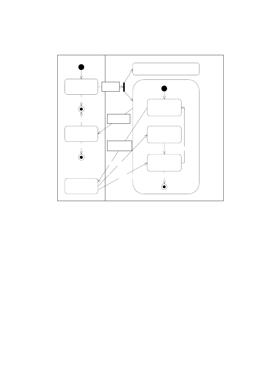
4.1.4 Use Case:
Edit
Break
Plans
Explicit information about interaction scenarios of the intended system is given in Sections
3.2.2 and 3.2.4 of the initial customer specication. This information pertains mainly to
the user interface and can, therefore, be demonstrated best with a prototype of the user
interface (see Section 4.1.7). Moreover, most of the dynamic behavior is self-evident in
the context of an interactive editor like the break planner system where the user is free
to perform most actions whenever he or she wants to. The use of special description
techniques for the system's dynamics is, therefore, hardly necessary in our case. We have
nevertheless included sequence and activity diagrams to demonstrate the use of UML's
modeling techniques for the description of user interactions.
The sequence diagram of Figure 3 shows a possible exemplary action sequence named
Edit
Session
assigned to the use case
Edit Break Plans
: A plan editor starts the break planner
application, chooses a break plan to edit and assigns two teachers to breaks before the
application is nally terminated. The system maintains a window with the actual break
statistics during the whole session.
Sequence diagrams can only describe exemplary action sequences|they do not specify the
required behavior of a user or the system exhaustively. To restrict the possible interactions
of a certain use case (or \business process") during system analysis, UML oers activity
diagrams. Figure 4 prescribes the workow of a single user editing a break plan: He or
she must rst decide whether an existing break plan shall be opened or a new plan shall
be created. After doing so, he or she can repeatedly assign teachers to breaks, unassign
teachers from breaks, print the plan, or look at the maintained statistics. Finally, the
break plan has to be closed.
To be consistent with the corresponding sequence diagrams, each sequence must be con-
sistent with the execution of the corresponding activity diagram's state automaton. As
can be seen from a comparison of Figures 3 and 4, this is true for our diagrams: As far
as actions from the activity diagram are concerned, the sequence diagram can be seen as
a trace of the activity diagram's state machine.
14
plan editor :
system
start break planner application
present break plan browser window
open break plan
assign teacher to break
update break statistics
assign teacher to break
update break statistics
destroy break plan editor window
present break plan editor window
terminate break planner application
present break statistics window
destroy break statistics window
destroy break plan browser window
close break plan
Plan Editor
Figure 3: Sequence Diagram
Edit
Break
Plans
::
Edit
Session
close break plan
[edit existing plan]
[edit new plan]
add breaks
create break plan
[another action]
[last action]
open break plan
assign teacher
to break
print break plan
unassign teacher
look at statistics
Figure 4: Activity Diagram
Edit
Break
Plans
::
Edit
a
Single
Break
Plan
15

4.1.5 Use Case:
Up
date
Break
Statistics
While the interactions during
Edit Break Plan
could be in principle demonstrated with
the help of a user interface prototype, there is another feature|namely,
Maintain Break
Statistics
in the context of more than one user|that can not be simulated easily by a
prototype because it requires the realization of most of the application's functionality.
The scenario in 3.2.2 says that \each time a teacher is assigned to a break, the break
statistics is updated". A similar principle applies to the presentation of break plans:
Whenever a break assignment conicts with another one, its representation in the user
interface should be updated to be visually distinguishable. The handling of updates could
be implemented in various ways:
Update on Request:
Users have to press an update button to request a window with
an actual version of the break statistics.
Interval Updates:
The break statistics window is updated automatically in distinct
time intervals.
Update on Change:
The break statistics window is updated whenever a break plan
changes. Hence changes of one user are immediately visible to other users.
Of these variants, the third seems to follow the customer specication most closely and
is, therefore, added to the requirements. However, we have also considered the other two
possibilities because they lead to much simpler implementations and enable some cong-
urations that are not possible with the third variant (see the section about bidirectional
communication in Section 5.2.2 on page 38).
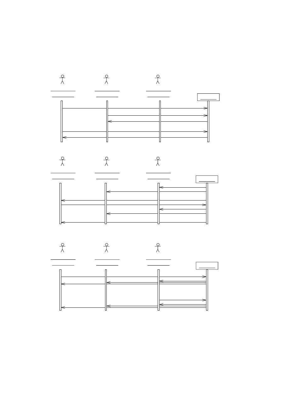
Each variant is associated with a dierent sequence diagram, as shown in Figure 5, where
the interactions between three users and the system are modeled. In contrast to the
diagram of Figure 3, these diagrams are not directly assigned to a certain use case because
they concern all use cases that have a
uses
-connection to
Maintain Break Statistics
: The
change
events in the sequence diagram arise during the execution of the use cases
Manage
Teachers
,
Edit Break Plan
, and
Manage Break Plans
, whereas the
update
events belong to
the use case
Maintain Break Statistics
.
4.1.6 Use Case:
Manage
Users
Activity diagrams can be very useful to show the embedding of the system's workows
into its organizational environment. Later on, these informations could be used to write
documentation and a user's guide for the application. We have added an activity diagram
for the
Add User
activity of the use case
Manage Users
to demonstrate this (see Figure
6): In order to perform actions concerning the access to the break planner program, some
organizational actions have to be performed as well. The following description of the
activity diagram explains this informally.
Manage Users :: Add User
The system administrator adds a user to the system and
provides him or her with a password. Users can be sta editors as well as plan
editors.
To gain access to the system, each user has to read and sign a special form provided
by the school (the system administrator may hand out the password only if a signed
form for the user has been led).
16
Plan Editor
plan editor 1 :
Plan Editor
plan editor 2 :
staff editor 1 :
Staff Editor
Plan Editor
plan editor 1 :
Plan Editor
plan editor 2 :
staff editor 1 :
Staff Editor
Plan Editor
plan editor 1 :
Staff Editor
update
update request
change
update request
update
system
a
b
c
d
e
f
update
update
update
update
update
update
change
{d - a = 5 sec}
{e - b = 5 sec}
{f - c = 5 sec}
system
update
change
update
update
update
update
change
update
system
Interval Update
Update on Change
Update on Request
Plan Editor
plan editor 2 :
staff editor 1 :
Figure 5: Possibilities for Update of the Break Statistics
17
The action states
add new account
and
allow remote internet access
contain the only
actions aecting the computer system to be realized. All other actions are outside of
the system boundary and must be performed manually by the system administrator.
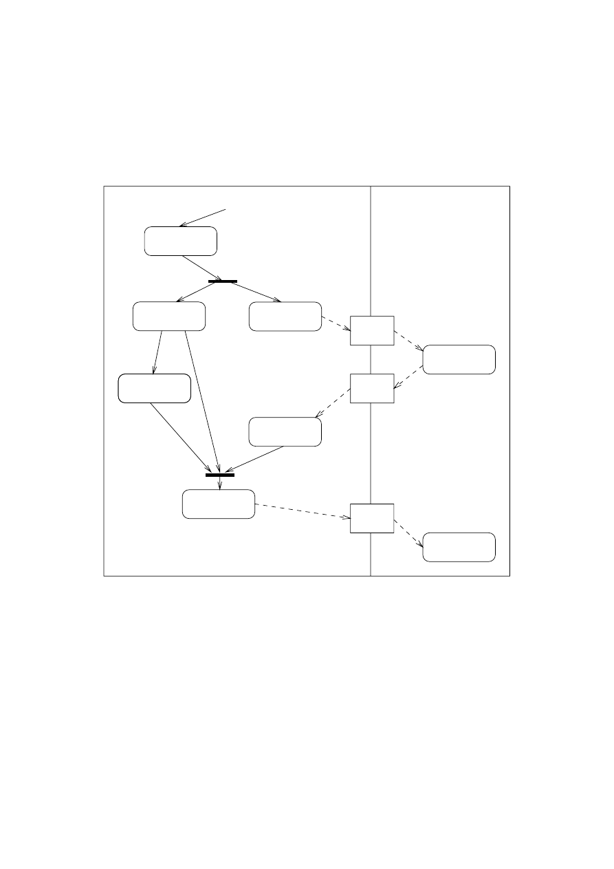
Figure 6 shows the corresponding activity diagram. In contrast to the activity diagram
in the previous section it involves two users.
password
System Administrator
User
prepare form
add new
account
sign form
file form
memorize
password
password
form
[signed]
form
[empty]
[remote
access
requested]
receive request
for new account
allow remote
internet access
access
[no remote
requested]
hand out
Figure 6: Activity Diagram
Manage
Users
::
Add
User
4.1.7 User Interface Prototype
A prototype is a good way to ensure that developers and customers share the same un-
derstanding of the system. Normally it is a quickly implemented program demonstrating
some aspects of the system, for example parts of the GUI layout and some of the possible
interactions between the user and the system. A prototype of this kind can be assigned
to one or more concerned use cases. It serves as an additional, very intuitive tool for
the description of the system's externally visible dynamic behavior and can often replace
sequence and activity diagrams.
18
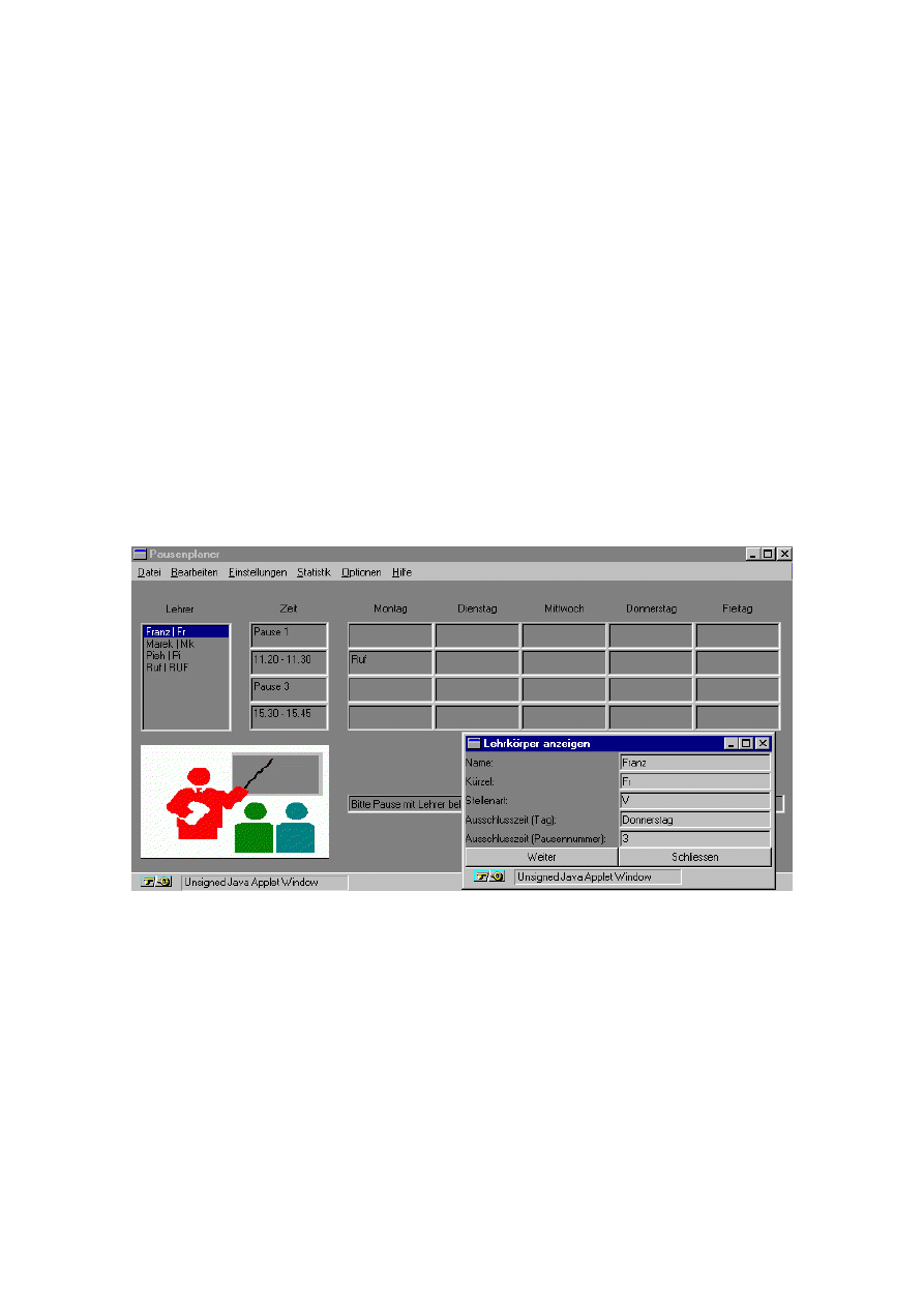
A rst, paper-based prototype of the user interface for plan editors is already provided
within the system vision of the customer specication. However, it gives only a very
rough impression and can not replace a computer-based prototype because its layout does
not conform with the nal tool and its dynamic behavior cannot be demonstrated to a
customer.
The development of the prototype on the Windows platform was performed by Klaus
Berg and Briktius Marek, our industrial partners at Siemens ZT. They used the Java
Development Kit Version 1.0.2 as described in [Fla96] and Symantec's Cafe Development
Environment for programming. In contrast to the successor tool Visual Cafe [Sym97], Cafe
has no integrated visual GUI builder, so the user interface was programmed manually. We
hope that the experience gained with this minimalistic approach will help us with a later
evaluation of dierent user interface tools and techniques.
The prototype includes only some parts of the system's user interface: Due to time con-
straints, the parts for the presentation of the break statistics and for system administration
were not created. The concerned use cases are, therefore, only
Manage Break Plans
,
Edit
Break Plans
, and
Manage Teachers
. Furthermore, the language of the GUI is German, as
stated in the original specication of the DACH group. Figure 7 shows a screen shot of
the prototype. The prototype itself can be downloaded via [BM97].
Figure 7: GUI Prototype for the Breakplanner Application
4.2 Class-Driven Analysis
4.2.1 Class Diagram
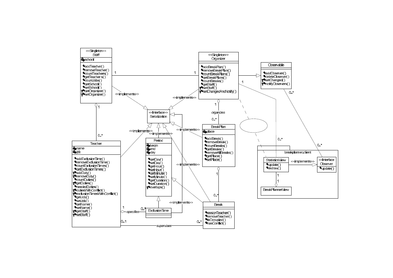
The analysis class diagram in Figure 8 contains the classes from the CRC-cards of Section
3.2.3 (with the
Break Planner
renamed to
Organizer
, to avoid confusion with the intended
application). Apart from that, two additional classes have been introduced:
19
3HULRG
GD\
EHJLQ
HQG
RYHUODSV
([FOXVLRQ7LPH
7HDFKHU
QDPH
MRE
QHHGHG'XWLHV
6WDWLVWLFV
FDOFXODWH
FRXQW%UHDNV
FRXQW-REV
6LQJOHWRQ!!
6WDII
VFKRRO
6LQJOHWRQ!!
%UHDN
KDV&RQIOLFW
VXSHUYLVHV
2UJDQL]HU
6LQJOHWRQ!!
%UHDN3ODQ
SODFH
RUJDQL]HV
$FFRXQW
QDPH
SDVVZRUG
NLQG
Figure 8: Analysis Class Diagram
20

Account
is responsible for the handling of the user accounts necessary to log into the
system.
ExclusionTime
models a weekly recurring period of time during which a certain
teacher can not be assigned to a break. We explicitly allow exclusion times like
\whole Tuesday" or \Wednesday, from 10:00 to 14:00".
To express that a class must have exactly one object instance at runtime, we have intro-
duced the
Singleton
stereotype for the classes
Organizer
and
Sta
. In the context of
the break planner, this models the implicitly given requirement that the break planner
application is used in a single school with a single teaching sta.
Statistics
is also a single-
ton because it represents the conceptually unique statistical values for the actual teaching
sta conguration, not a sheet of paper with a statistics on it.
Compared to the responsibilities on the CRC-cards, the classes in the diagram of Figure
8 contain much fewer entries. This has the following reasons:
Some pairs of responsibilities were transformed into attributes. An example is the
pair
enter name
/
return name
of the CRC-card
Teacher
, which was transformed to the
attribute
name
of class
Teacher
.
Some responsibilites are covered by associations. A typical case are the four re-
sponsibilities
assign a teacher to a break
,
remove teacher from break
,
return teacher
supervising a break
, and
return the breaks supervised by a teacher
of the CRC-card
Break Plan
. They have been transformed to the association
supervises
between the
classes
Teacher
and
Break
. The information that
Break Plan
instances are respon-
sible for managing the links between
Teacher
and
Break
objects is omitted during
this transformation|we think that this decision should be delayed until the design
phase.
4.2.2 Data Dictionary of Analysis Classes
This section contains the data dictionary for each class found in Figure 8. We did neither
include information about the datatypes of the attributes nor about the signatures of the
methods because this is part of the design process. Also, associations are left out as they
can be seen best in the class diagram.
Account
A user account.
Attributes
name
A user's name.
password
A user's password.
kind
Indicates whether the account belongs to a plan editor or a sta editor.
Break
A break to be supervised by a teacher. Each break has the same weight with
respect to a teacher's supervision duties.
inherits from
Period
Operations
hasConict()
Indicates that the assigned teacher is assigned to another break
at the same time or that the break overlaps with one of his or her exclusion
times.
21

BreakPlan
A collection of the breaks to be supervised by teachers in a certain part of
the school building. The breaks of a break plan must not overlap.
Attributes
place
The name of the school's building part where the supervising teachers are
positioned.
ExclusionTime
A period of time during which the corresponding teacher cannot supervise
any breaks.
inherits from
Period
Organizer
The organizer manages a collection of breaks plans. There exists exactly one
organizer instance.
Period
A weekly recurring period of time during a single day.
Attributes
day
The day of the week of the period.
begin
The start time of the period.
end
The end time of the period.
Operations
overlaps()
Determine whether two periods of time overlap.
Sta
The teaching sta of the school for which the breaks are planned. There exists
exactly one sta instance.
Attributes
school
A name identifying the school of the teaching sta.
Statistics
The statistics is calculated for the organizer and shows how many breaks each
teacher supervises already, how many breaks he or she has to supervise, and how
many breaks to be supervised as well as job shares exist. There exists exactly one
statistics instance.
Operations
calculate()
Compute the values for the statistics.
countBreaks()
Count the total number of breaks of all break plans of the orga-
nizer.
countJobs()
Count the total number of jobs of all teachers (for an explanation
of jobs see the
job
attribute of class
Teacher
).
Teacher
A teacher who has to supervise breaks.
Attributes
name
The name of the teacher.
job
The percentage of the teacher's part time job compared to a full-time job.
Operations
neededDuties()
The number of breaks a teacher has to supervise, based on the
total number of breaks and the number of available teachers, weighted ac-
cording to their job share. If the resulting number is a fraction, the plan
editor has to decide whether it should be rounded up or rounded down.
22
4.2.3 Class State Diagrams
The data items of the break planner application do not have complicated life cycles: Their
attributes can be changed at will during their lifetime and do not obey time-dependent
state invariants. Therefore, we decided to include only one class state diagram to express
the information about the possibilities for invalid break assignments of a teacher:
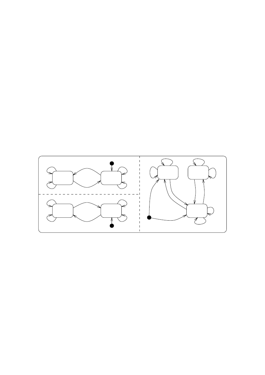
Possible Supervision Assigment Conicts:
Exclusion Overlap
Teacher assigned to break overlapping with one of his or her ex-
clusion times.
Too Many / Too Few Duties
Number of teacher's break assignments is too large or
too small for his or her supervision duty.
Break Conict
Teacher assigned to two breaks at the same time on dierent break
plans.
The corresponding class state diagram for the class
Teacher
is shown in Figure 9. The
events
addDuty
and
removeDuty
correspond to the creation and deletion of
supervises
-
associations between a
Teacher
and a
Break
in the class diagram in Figure 8.
removeDuty
[no overlap]
addDuty
addDuty [overlap]
addDuty
removeDuty
addDuty
[overlap]
removeDuty
addDuty
removeDuty [no conflict]
removeDuty [no overlap]
addDuty [conflict]
[no conflict]
addDuty
[conflict]
removeDuty
break
conflict
exclusion
overlap
no
overlap
no
conflict
removeDuty
addDuty
[proper]
[proper]
[too
few]
[proper]
removeDuty
addDuty
[too many]
[too few]
removeDuty
addDuty
[proper]
removeDuty [proper]
proper
duties
duties
too few
duties
too many
addDuty
[too few]
removeDuty
[too many]
Figure 9: State Diagram for Class
T
eacher
Exclusion overlaps and break conicts must be visualized to the user in the break plan, for
example by using special graphical symbols or colors to display conicting or overlapping
breaks. Similarly, teachers with conicts or too many/too few duties could be visualized
in the break statistics.
5 System Design
Our strategy during this phase was to design the business-oriented data and functional-
ity of the system before determining its distribution architecture. Apart from providing
additional structure for the development documents, this has the advantage that many
basic design decisions can be met without getting involved with the complexities of the
underlying distribution architecture. Because functional and non-functional aspects are
23

clearly separated, the functional design is more or less independent from the technical as-
pects of a certain distribution architecture, simplifying the transition to other distribution
architectures.
5.1 Business-Oriented Design
The essential step during business-oriented design is to construct a more detailed, rened
and implementation-oriented class diagram from the analysis class diagram. The other
description techniques are mainly used to show certain views onto this class model or to
specify the dynamic behavior of its classes and operations. Setting the design focus on
the classes of the system makes the transition to the nal implementation easier because
classes are the prevalent structuring construct of object-oriented program code.
Building the business-oriented design class model involves the following development ac-
tions:
1. Some analysis classes can be adopted for system design without changing their name,
functionality, or attributes.
2. Analysis classes can be dropped because they denote concepts not implemented by
means of classes in the nal system.
3. Analysis classes can be merged together or be split up. This can be done for various
reasons, for example to optimize access paths, to cache data for safety reasons, or
to rene complex analysis classes.
4. New classes, attributes, and operations necessary for modeling technical concepts of
the intended implementation can be introduced.
In our case, almost all classes from the analysis class diagram of Figure 8 have been
adopted in the business-oriented design class diagram given in Figure 10. Only
Account
has been dropped, and the functionality of
Statistics
has been split up to other classes.
Finally,
Observer
and the whole package
breakplanner.client
have been introduced to model
the integration of the user interface and to implement the Update on Change policy for the
break statistics (see Section 4.1.5). All of these changes are described in detail in Sections
5.1.1 to 5.1.6. Finally, Section 5.1.7 contains a data dictionary of all business-oriented
design classes.
5.1.1 Transforming the Analysis Class Diagram
Account
is not contained in the business-oriented design class diagram of Figure 10 because
our intended implementation platform provides already suitable account and authorization
mechanisms, e.g. http logins and le access modes. As a consequence, the implementation
of an own account mechanism is unnecessary, and the use case
Manage Users
and the class
Account
fall outside the system boundary of the intended program.
Statistics
was also not adopted. The reason for this is that
Statistics
is rather a collection
of special-purpose functions than a \normal" class: It has neither attributes nor does it
participate in non-trivial associations and is thus not used to hold data. Instead, the class
computes certain values from the attributes of the other classes (see the description of the
class in the data dictionary in Section 4.2.2). During design it is a common problem how
24

to handle such special-purpose functionality. In general there are two ways to solve this
problem:
The architect can design a synthetic class responsible for the functionality. The
advantage of this approach is that the centralized, \compact" representation of the
functionality can be easily understood and used by other programmers. The disad-
vantage is that the synthetic class needs references to most of the other classes and
their associations and is, therefore, very fragile with respect to changes of these.
The architect can split the functions among the dierent classes they naturally be-
long to, resulting in a simple and straightforward design. The disadvantage is that
functionality belonging together is now scattered over several classes, obfuscating
the access from outside.
Although clear rules cannot be established, experience indicates that usually the second
solution should be preferred, at least if it does not result in a plethora of operations
obfuscating the real purpose of the classes. For this reason we decided to distribute
the analysis functions for the calculation of statistics to other classes (see Figure 10):
countBreaks
was assigned to
Organizer
,
countJobs
was assigned to
Sta
, and
calculate
was
integrated into the
update
method of the newly introduced GUI class
StatisticsView
(see
Section 5.1.2).
5.1.2 User Interface Design
The analysis class diagram does not specify how multiple users of the system can access the
system's data at the same time. A technical solution to this problem is the introduction
of view classes responsible for the presentation and manipulation of the data. The new
sub-package
breakplanner.client
in Figure 10 is intended to contain all of these view classes
for the break planner application's GUI.
Although there exist many dierent view classes for the presentation of the dierent data
entities of the break planner, we have modeled only two exemplary classes: The
Statis-
ticsView
controls a window with the statistics data, and the
BreakPlannerView
represents
the main window of the break planner application. We think that the decision to leave out
most of the view classes is reasonable because these view classes can be \modeled" and
implemented easily with the help of an interactive GUI tool. Yet, we wanted to include at
least one of the view classes into our design because it is needed to model the interaction
between the application's GUI and the system core (for a detailed explanation see Section
5.1.3). Another reason for the inclusion of
StatisticsView
is that it contains some of the
application's functionality, namely the
update
method which is responsible for calculating
the statistics.
5.1.3 Realization of Update on Change
An advanced requirement for the break planner application is the immediate update of
the user interfaces. Each time a user changes a data value, the break statistics has to be
updated. The same principle applies to the visualization of conicting break assignments
according to Section 4.1.5. To realize this Update on Change policy, we have used the
so-called \observer pattern" (see [GHJV95] for details).
25
O bserver
Observable
Observer
Figure
10:
Business-Orien
ted
Design
Class
Diagram
26
The collaboration diagram of Figure 11 shows the dynamic behavior of the observer pat-
tern:
Observer
objects register at the
Observable
objects they are interested in by calling
the latter's
addObserver()
method; unregistering is done via calling
deleteObserver()
. Each
time a user changes an
Observable
's data, the
Observable
calls the
update()
method of each
registered
Observer
. The called
Observer
can then react on the change of the
Observable
,
for example by requesting the modied data from the
Observable
.
REVHUYHU 2EVHUYHU
REVHUYDEOH 2EVHUYDEOH
^WULJJHUHG E\ 2EVHUYHU FUHDWLRQ UHVS GHOHWLRQ`
VHW&KDQJHG
QRWLI\2EVHUYHUV
XVHU 8VHU
DGG2EVHUYHU
GHOHWH2EVHUYHU
XSGDWH
FKDQJH GDWD
Figure 11: Collaboration Diagram of the Observer Pattern
UML provides a notation to represent design patterns within a class diagram. An example
for this is given in Figure 10, where the observer pattern is represented by a dotted ellipse
to which the classes
StatisticsView
and
Organizer
are connected by dotted lines. The
meaning of this notation is that
StatisticsView
plays the role of the
Observer
, whereas
Organizer
acts as an
Observable
.
The implementation of the observer pattern in Java is done via implementation/extension
of the available framework classes/interfaces
Observer
and
Observable
(see also section 5.2
and 6.3).
To further clarify the internal events of the system in reaction to a user request, we have
included the sequence diagram in Figure 12. It is a rened, more detailed version of the
sequence diagram for the Update on Change policy in Figure 5. The new version presents
rened message ows for the
change
and
update
messages of the corresponding analysis
diagram.
5.1.4 Management of Associations
Another area of concern during business-oriented design is the management of the asso-
ciations between the classes. The following issues are important:
The responsibility for creation and destruction of association instances has to be
assigned to certain classes. Usually, one of the associated classes manages the asso-
ciation exclusively, but it is also possible that both associated classes or even other
classes are involved.
27
SODQ(GLWRU
3ODQ
(GLWRU
EUHDN3ODQQHU9LHZ
%UHDN3ODQQHU9LHZ
EUHDN3ODQQHU9LHZ
%UHDN3ODQQHU9LHZ
VWDWLVWLFV9LHZ
6WDWLVWLFV9LHZ
VWDWLVWLFV9LHZ 6WDWLVWLFV9LHZ
EUHDN
%UHDN
RUJDQL]HU
2UJDQL]HU
SODQ(GLWRU
3ODQ
(GLWRU
DVVLJQ
EUHDN
WR
WHDFKHU
DVVLJQ7HDFKHU
VHW&KDQJHG$QG1RWLI\
VHW&KDQJHG
QRWLI\2EVHUYHUV
XSGDWH
LV2FFXSLHG
KDV&RQIOLFW
UHGUDZ
XSGDWH
LV2FFXSLHG
KDV&RQIOLFW
UHGUDZ
UHFRJQL]H
FKDQJHV
UHFRJQL]H
FKDQJHV
PRUH
PHVVDJHV
UHWULHYLQJ
DOO
LQIRUPDWLRQ
WR
VKRZ
DFWXDO
EUHDN
VWDWLVWLFV
PRUH
PHVVDJHV
UHWULHYLQJ
DOO
LQIRUPDWLRQ
WR
VKRZ
DFWXDO
EUHDN
VWDWLVWLFV
Figure 12: Sequence Diagram for the
Up
date
on
Change
policy
28

The directions of the access paths of the associations have to be xed. Usually,
unidirectional access paths are sucient for most associations, and the traversal
direction is only from the managing class to the associated class.
In our application, most of the associations are aggregations managed by the composite
object, and the traversal direction is only from the composite object to the contained
object. This results in the following, typical pattern of operations in a Java class, where
<
Class
>
represents the class of the composite object and
<
Element
>
represents the class
of the contained objects:
void
<
Class
>
::add
<
Element
>
(Element)
, e.g.
void Sta::addTeacher(Teacher)
void
<
Class
>
::remove
<
Element
>
(Element)
, e.g.
void Sta::removeTeacher(Teacher)
int
<
Class
>
::count
<
Element
>
s()
, e.g.
int Sta::countTeachers()
Enumeration
<
Class
>
::get
<
Element
>
s()
, e.g.
Enumeration Sta::getTeachers()
The remaining associations between the two singleton classes
Sta
and
Organizer
and the
supervises
-association between
Teacher
and
Break
are both bidirectional: A
Break
needs
a link to its supervising
Teacher
to determine whether its assignment causes a conict
with other breaks of the teacher. Analogously, a
Teacher
needs a link to its
Organizer
to
calculate the share of the total duties he or she has to occupy.
5.1.5 Break Conict Detection
Break supervision conicts must be visualized by highlighting conicting breaks in the
GUI (see sections 3.2.2 and 4.2.3). To support this feature, method
Break::hasConict
determines whether the break assignment results in one of the states
break conict
or
ex-
clusion overlap
for the assigned teacher (cf. Figure 9). The implementation of this method
is rather complex because it usually involves several objects connected by association links
and has a non-trivial control ow.
We have, therefore, provided the activity diagram in Figure 13 to specify the behaviour
of this method. The diagram contains two dierent kinds of control states: States with
names following the pattern
<
class name
>
::
<
method name
>
correspond to method calls;
all other states correspond to the execution of code sections in a method.
As the diagram shows, a
Break
is involved in a conict if it is occupied by a
Teacher
,
and either the call to the method
Teacher::exclusionTimesWithConict()
or to the method
Teacher::dutiesWithConict()
returns an overlapping
Period
. The method
Teacher::duties
WithConict()
is further rened: It checks for all duties whether they overlap with a given
duty, and returns the overlapping
Period
. We did not rene the method
Teacher::exclusion
TimesWithConict()
because it is very similar to
Teacher::dutiesWithConict()
|instead of
having to go through
Period
objects, one has to go through
ExclusionTime
objects.
5.1.6 Persistence Management
The break planner application needs to store its data persistently because informations
about breaks plans and stas are valid for long periods of time and must survive multiple
runs of the system. For our system we decided to use the standard Java object serial-
ization mechanism in combination with plain les because this seemed sucient for the
management of the relatively small amount of data. Furthermore, this mechanism can be
29
%UHDN
%UHDNKDV&RQIOLFW
QR FRQIOLFW
FRQIOLFW
7HDFKHU
>QRW RFFXSLHG@
>HPSW\@
>QRW HPSW\@
7HDFKHUH[FOXVLRQ7LPHV:LWK&RQIOLFW
7HDFKHUGXWLHV:LWK&RQIOLFW
%UHDNLV2FFXSLHG
LV 6HW2I'XWLHV
HPSW\
WDNH D GXW\
VWRUH GXW\ LQ
6HW2I'XWLHV
DOO GXWLHV GRQH
'XW\
>'XW\ VHOI@
%UHDNRYHUODSV
'XW\'XW\
>'XW\ 'XW\@
>RYHUODSSLQJ@
>QRW RYHUODSSLQJ@
>DOO GRQH@
>VRPH OHIW@
6HW2I'XWLHV
Figure 13: Activity Diagram for Method
Break::hasConict
easily used by simply deriving classes from the interface
Serializable
. In the class diagram
of Figure 10, this was done for all classes adopted from the analysis class diagram. Ob-
ject graphs consisting of objects of these classes can then, for example, be provided to a
standard Java
ObjectOutputStream
object and mapped to a le.
The choice of a persistence mechanism usually constrains the distribution architecture:
The decision to use a monolithic object-oriented database system would for example in
most cases lead to an architecture where the data is centralized on the database server.
This holds also for our system: Although object serialization is a Java feature that can be
used everywhere|on a client as well as on a server|, one can not store data persistently
from within a client applet running on a Java-capable browser (cf. Section 5.2.1).
5.1.7 Data Dictionary of Business-Oriented Design Classes
This section provides the data dictionary for each class contained in Figure 10. Although
all attributes and operations of the classes are enclosed, we have not included descriptions
for trivial operations in order to keep the size of the dictionary manageable.
30

Interfaces:
Observer
An object implementing the interface
Observer
can register itself at observable
objects. The observable object noties the observer object if necessary.
Public Operations
update()
Indicates that the state of one or more observable objects has changed.
Serialization
Objects of classes implementing the
Serialization
interface can be stored in
an
ObjectStream
. Mapping the stream to a le makes the objects persistent.
Classes:
Break
A break to be supervised by a teacher. Each break has the same weight with
respect to a teacher's supervision duties.
inherits from
Period
Public Operations
assignTeacher()
Assigns a teacher to the break.
removeTeacher()
Disassigns the teacher from his or her supervision.
isOccupied()
Indicates whether the break is supervised.
hasConict()
Indicates that the assigned teacher is assigned to another break
at the same time or that the break overlaps with one of his or her exclusion
times.
BreakPlan
A collection of the breaks to be supervised by teachers in a certain part of
the school building. The breaks of a break plan must not overlap.
implements
Serialization
Private Attributes
place
The name of the school's building part where the supervising teachers are
positioned.
Public Operations
addBreak(), removeBreak(), countBreaks(), getBreaks()
removeAllBreaks()
Removes all breaks from the breakplan.
getPlace(), setPlace()
BreakPlannerView
A GUI class, representing the break planner client's main application
window.
ExclusionTime
A period of time during which the corresponding teacher cannot supervise
any breaks.
inherits from
Period
ObjectStream
An abstraction of the break planner's persistence mechanism which uses
the interface Java
Serialization
mechanism to read/write serialized object graphs
from/to a stream mapped to a le.
Observable
Observables can be observed by objects that implement the
Observer
inter-
face. If the observable object changes it noties all registered observers.
Public Operations
addObserver()
Adds an observer object to the collection of observers.
31

deleteObserver()
Removes an observer object from the collection of observers.
Protected Operations
setChanged()
Indicates that the observable has changed.
notifyObservers()
Noties all observers if the observable has changed.
Organizer
inherits from
Observable
implements
Serialization
Public Operations
addBreakPlan, removeBreakPlan(), countBreakPlans(), getBreakPlans()
countBreaks()
Count the total number of breaks of all break plans of the orga-
nizer.
getSta()
Protected Operations
setSta()
setChangedAndNotify()
Indicates that the organizer or another relevant object
has changed and noties all observers.
Period
A weekly recurring period of time during a single day.
implements
Serialization
Private Attributes
begin
The start time of the period.
end
The end time of the period.
day
The day of the week of the period.
Public Operations
getDay(), setDay(), getHour(), setHour(), getMinute(), setMinute()
getDuration(), setDuration()
Protected Operations
overlaps()
Sta
implements
Serialization
Private Attributes
school
A name identifying the school of the teaching sta.
Public Operations
addTeacher(), removeTeacher(), countTeachers(), getTeachers()
countJobs()
Count the total number of jobs of all teachers (for an explanation
of jobs see the
job
attribute of class
Teacher
).
getSchool(), setSchool()
Protected Operations
getOrganizer(), setOrganizer()
StatisticsView
A GUI class, representing the break planner client's statistics window.
implements
Observer
Public Operations
32

redraw()
Redraws the statistics view on the screen.
update()
Updates the statistics windows when the data managed by the corre-
sponding
Organizer
has changed. To do that, the method rst calculates the
new values for the statistics (see the description of the method
calculate()
of class
Statistics
in the data dictionary of the analysis classes of Section
4.2.2) and then calls
redraw()
.
Teacher
A teacher who has to supervise breaks.
implements
Serialization
Private Attributes
name
The name of the teacher.
job
The percentage of the teacher's part time job compared to a full-time job.
Public Operations
addExclusionTime(), removeExclusionTime(), countExclusionTimes()
getExclusionTimes()
countDuties()
neededDuties()
The number of breaks a teacher has to supervise, based on the
total number of breaks and the number of available teachers, weighted ac-
cording to their job share. If the resulting number is a fraction, the plan
editor has to decide whether it should be rounded up or rounded down.
getJob(), setJob(), getName(), setName()
Protected Operations
addDuty(), removeDuty(), getDuties()
dutiesWithConict()
Returns all duties overlapping with a given break.
exclusionTimesWithConict()
Returns all exclusion times overlapping with a
given break.
getSta(), setSta()
5.2 Distribution Design
Distribution design is concerned with the partitioning of the data and functionality of a
system on a network of physically or logically distributed computation nodes. At this
point, the constraints induced by the target hardware and the base software system have
to be considered.
5.2.1 Choice of Distribution Architecture
Target System
One of the requirements stated during requirements analysis was that
plan editors may \work at home over the internet with a Java-capable browser" (see
Section 4.1.3). The distribution architecture is restricted considerably by this requirement
because it implies that GUI objects are managed by applets running on client computers.
We do not consider form-based GUIs because they can not provide the look-&-feel required
by the customer specication (see Section 3.2.4).
The requirement also implies the existence of at least one server with a \real" Java appli-
cation that can handle persistent information|applets running on browsers are usually
forbidden to access local les according to the sandbox safety model of Java [Jav97].
33

Partitioning the Application Objects
The partitioning of the break planner's
application objects is more dicult. A rst approach is suggested by Section 4.1.3 of the
analysis document: It states that break plans can be edited by exactly one plan editor at
a time, whereas teaching sta and teacher data are shared among all plan editors. This
seems to imply a simple check-out/check-in solution for break plans, where users check
out break plans from a central repository, edit them locally, and check them in again.
Such an architecture has the advantage that interactive editing of break plans is very
fast because it is performed locally without communication overhead between distributed
nodes.
However, a closer inspection shows that a simple check-out/check-in architecture with lo-
cal editing is not a proper solution because every user needs an up-to-date break statistics
(see Sections 3.2.2 and 3.2.4). If a user assigns a teacher to a break in a single break plan,
the statistics views of all other users have to be updated.
To support the Update on Change strategy of the break statistics, we considered two
alternatives:
Enhancing the Check-Out/Check-In Solution
One possibility is to send change notication messages from each client to all other
clients on each break plan update. This could be implemented easily if Java provided
a transparent object migration facility keeping track of references to mobile objects.
However, because such a mechanism does not exist in RMI, it would require the
implementation of a proprietary, albeit small object request broker doing all the
bookkeeping. We can also imagine a variant with replication, where all break plans
are duplicated on the server, and the changes on clients are written through to the
server so that the other clients can observe them.
Holding All Application Objects on the Server
The other possibility is to hold the application objects (including the break plans)
on the server and to leave only the view objects on the clients.
The essential advantage of the second alternative is that it is simple and robust and leads
to a exible, easily extendable design. The only drawback is that interactive editing of
break plans is slower than with the rst alternative because the clients have to access
remote server data for each user action. However, we believe that the delays will be
tolerable in a small school network with low network trac, and have chosen the second
alternative. As an additional feature, this solution allows concurrent access also for sta
editors, which is an enhancement compared to the initial customer requirements.
Component Diagram of Distribution Architecture
The component diagram
in Figure 14 shows the resulting distribution architecture: The package
breakplanner.client
represents the GUI objects on the local client PCs. The package
breakplanner.server
rep-
resents the objects on the central server responsible for the application's functionality
and persistent data management. The packages
breakplanner.api
and
com.cariboulake.util
form the bridge between the clients and the server: They contain so-called RMI \stub"
and \skeleton" objects that run on the client and the server, respectively (the technical
concepts and implications of RMI are explained in the following section). While
breakplan-
ner.api
builds these bridges for the server-resident objects of the classes
Sta
,
Teacher
,
Pe-
riod
,
ExclusionTime
,
Organizer
,
BreakPlan
, and
Teacher
,
com.cariboulake.util
realizes them
for a distributed variant of Java's observer classes.
34
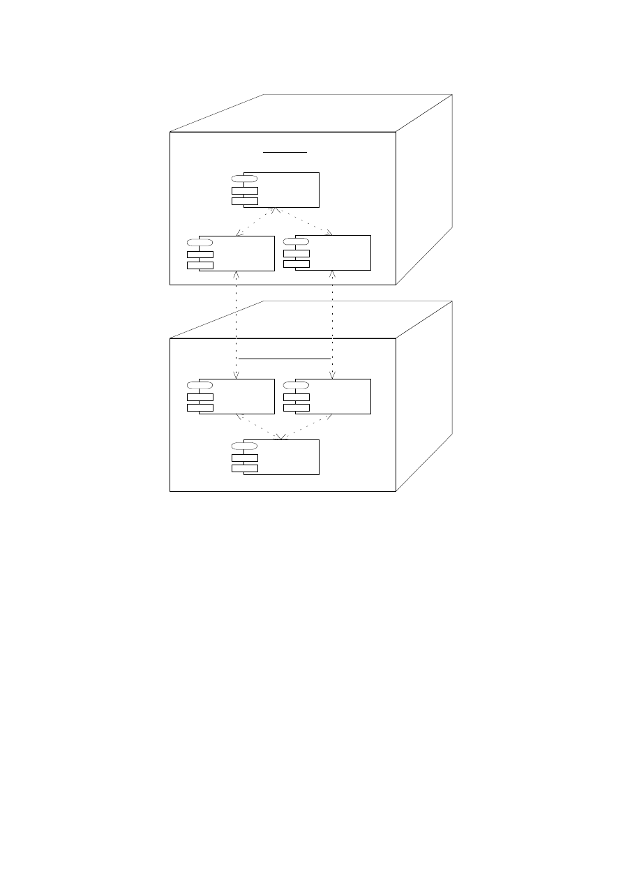
Client PC
breakplanner.
client
COM.
cariboulake.util
breakplanner.
api
Server Workstation
breakplanner.
server
COM.
cariboulake.util
breakplanner.
api
Figure 14: Component Diagram Illustrating the Distribution Architecture
Diagram 14 can also serve as a deployment diagram showing the physical distribution of
the code needed to run the application. However, deployment diagrams are not very useful
in the context of the Java framework: The deployment of (byte-)code is not a critical task
because bytecode can be downloaded automatically at runtime and does not have to be
installed manually.
5.2.2 Realization with RMI
Client Interfaces and Server Implementation Classes
The changes between
the business-oriented and the distribution-oriented architecture class diagram (see Figures
10 and 5.2.2 on page 37) are simple and almost schematic, as proposed in SUN's tutorial for
Java RMI [SUN97c]: Each class whose objects must be accessed from the client is split up
into an interface and an implementation class. The interfaces contain the funcionality used
by the client; they are derived from the standard interface
Remote
and are given the names
of the original classes. The implementation classes are used on the server; they are derived
from class
UnicastRemoteObject
, and their names are suxed with
Impl
. An example is
35

the business-oriented design class
Break
which was split up into the distribution-oriented
design class
BreakImpl
and the corresponding interface
Break
.
Remote Observer Mechanism
Instead of the standard Java class
Observable
, a
remote version has to be used, because observer and observable objects are on dierent
sides of the client/server-gap. We could use the implementation provided in a freely
available package from Caribou Lake Software [Car97]. Unfortunately, the name of the
observable implementation class of this package violates the usual naming conventions:
Instead of
COM.cariboulake.util.Observable
it should better be
COM.cariboulake.util.Remote
ObservableImpl
.
Note that the GUI class
StatisticsView
has to be a remote class, too, because its objects
observe the
Organizer
object lying on the application server. Therefore, these client objects
must themselves be remote servers for the
Organizer
object's callbacks to their
update
-
method (the control ow with RMI for this case is explained in detail below).
Restricting the Client's Functionality
On the one hand, a client of a class should
be oered sucient functionality to use the class eectively and comfortably for its in-
tended purpose. On the other hand, clients should not be allowed to access any additional
functionality. This very important design principle makes it easy to change the implemen-
tation of methods hidden from the client|it is also known as the principle of \shallow
interfaces" or \loose coupling".
The standard way to achieve this principle in the context of Java is to annotate features
of a class with access modiers like
private
to hide the features from other classes. In the
context of RMI, another approach is used: Clients are provided with restricted interfaces,
containing subsets of the full class signature. This way a server implementation class can
be derived from several interfaces oering dierent subsets of the functionality.
Having a look at our example we can distinguish two dierent users of the implementation
classes:
Clients have access to a rather limited interface. Apart from conicting with the prin-
ciple of shallow interfaces, granting all clients access to all server features would open
a potential security hole. Clients are, for example, not allowed to connect a
Teacher
to
a
Break
via the method
Teacher::addDuty()
because this method does not ensure the
bidirectionality of the
supervises
-association, as the method
Break::assignTeacher()
does.
The server must have access to the full functionality of the implementation classes.
The restriction of the client's functionality can be seen in the class diagram of Figure
5.2.2 on page 37. The client interfaces contain only parts of the functionality of their cor-
responding server implementation classes, and the
PeriodImpl
class has no client interface
at all and is, therefore, hidden from the client entirely.
Introduction of
BreakPlanner
Class
A new singleton class
BreakPlanner
is intro-
duced that represents the entry point for clients on the server (see upper right corner of
Figure 5.2.2 on page 37). At runtime, the
BreakPlanner
object is registered via the
rmireg-
istry
mechanism [SUN97c]. This allows the clients to access the entire application object
36
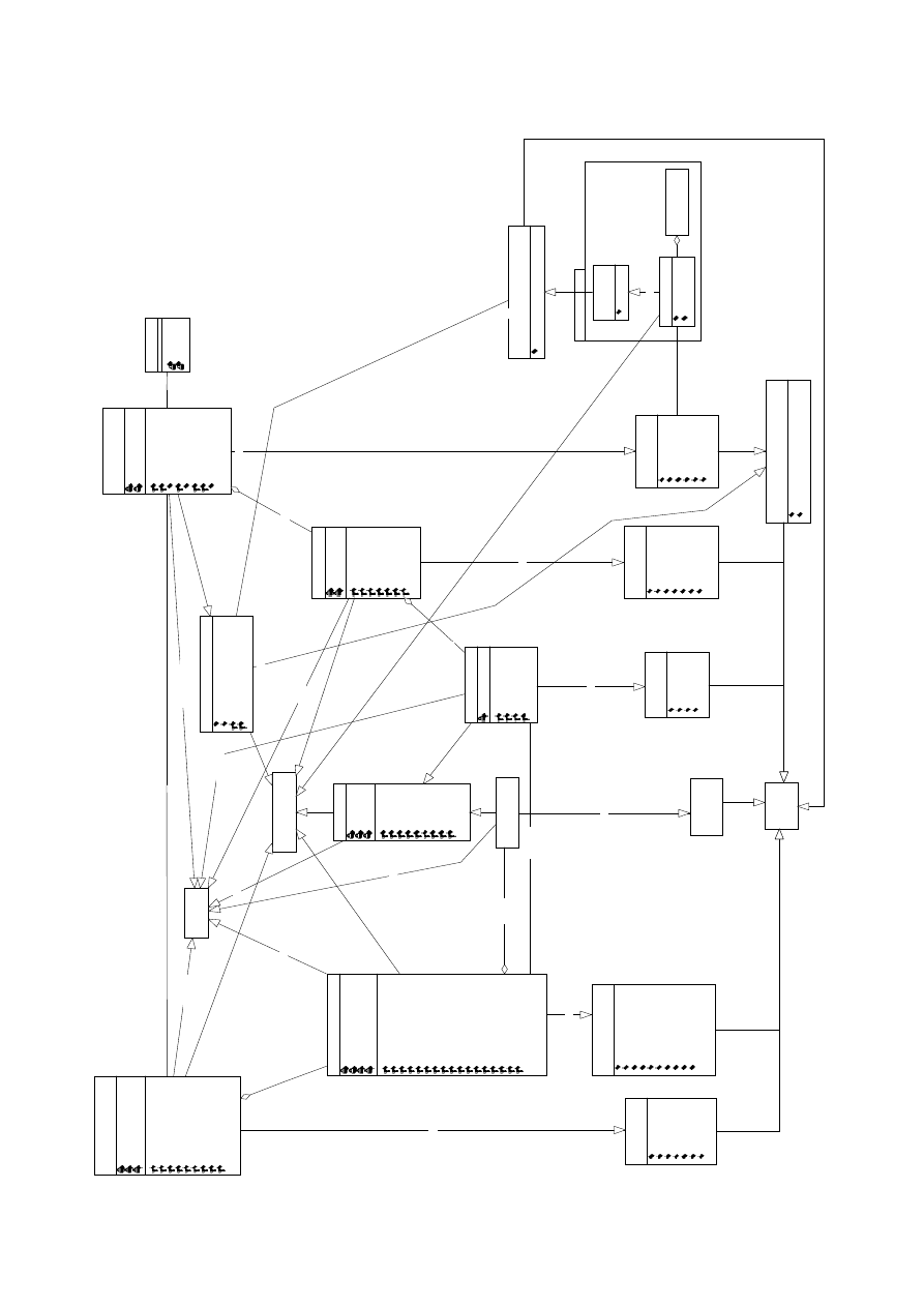
8QLFDVW5HPRWH2EMHFW
5HPRWH
,QWHUIDFH!!
EUHDNSODQQHUFOLHQW
6HULDOL]DWLRQ
,QWHUIDFH!!
([FOXVLRQ7LPH
,QWHUIDFH!!
%UHDN
DVVLJQ7HDFKHU
UHPRYH7HDFKHU
LV2FFXSLHG
KDV&RQIOLFW
,QWHUIDFH!!
7HDFKHU
DGG([FOXVLRQ7LPH
UHPRYH([FOXVLRQ7LPH
FRXQW([FOXVLRQ7LPHV
JHW([FOXVLRQ7LPHV
FRXQW'XWLHV
QHHGHG'XWLHV
JHW-RE
VHW-RE
JHW1DPH
VHW1DPH
,QWHUIDFH!!
%UHDN3ODQ
DGG%UHDN
UHPRYH%UHDN
FRXQW%UHDNV
JHW%UHDNV
UHPRYH$OO%UHDNV
JHW3ODFH
VHW3ODFH
,QWHUIDFH!!
6WDII
DGG7HDFKHU
UHPRYH7HDFKHU
FRXQW7HDFKHUV
JHW7HDFKHUV
FRXQW-REV
JHW6FKRRO
VHW6FKRRO
,QWHUIDFH!!
([FOXVLRQ7LPH,PSO
%UHDN,PSO
P'XW\
7HDFKHU,PSO
DVVLJQ7HDFKHU
UHPRYH7HDFKHU
LV2FFXSLHG
KDV&RQIOLFW
7HDFKHU,PSO
P1DPH
6WULQJ
P-RE
IORDW
P([FOXVLRQV
9HFWRU
P'XWLHV
9HFWRU
DGG([FOXVLRQ7LPH
UHPRYH([FOXVLRQ7LPH
FRXQW([FOXVLRQ7LPHV
JHW([FOXVLRQ7LPHV
DGG'XW\
UHPRYH'XW\
FRXQW'XWLHV
JHW'XWLHV
QHHGHG'XWLHV
GXWLHV:LWK&RQIOLFW
H[FOXVLRQ7LPHV:LWK&RQIOLFW
JHW-RE
VHW-RE
JHW1DPH
VHW1DPH
JHW6WDII
VHW6WDII
VSHFLILHV
VXSHUYLVHV
%UHDN3ODQ,PSO
P3ODFH
6WULQJ
P%UHDNV
9HFWRU
DGG%UHDN
UHPRYH%UHDN
FRXQW%UHDNV
JHW%UHDNV
UHPRYH$OO%UHDNV
JHW3ODFH
VHW3ODFH
6WDII,PSO
P6FKRRO
6WULQJ
P7HDFKHU
9HFWRU
P2UJDQL]HU
2UJDQL]HU,PSO
DGG7HDFKHU
UHPRYH7HDFKHU
FRXQW7HDFKHUV
JHW7HDFKHUV
FRXQW-REV
JHW6FKRRO
VHW6FKRRO
JHW2UJDQL]HU
VHW2UJDQL]HU
6LQJOHWRQ!!
2UJDQL]HU,PSO
P%UHDN3ODQV
9HFWRU
P6WDII
6WDII,PSO
DGG%UHDN3ODQ
UHPRYH%UHDN3ODQ
FRXQW%UHDN3ODQV
JHW%UHDN3ODQV
FRXQW%UHDNV
JHW6WDII
VHW6WDII
VHW&KDQJHG$QG1RWLI\
6LQJOHWRQ!!
RUJDQL]HV
%UHDN3ODQQHU
VWDUW6HUYHU
VWRS6HUYHU
3HULRG,PSO
P%HJLQ
7LPH
P(QG
7LPH
P'D\
'D\
RYHUODSV
JHW'D\
VHW'D\
JHW+RXU
VHW+RXU
JHW0LQXWH
VHW0LQXWH
JHW'XUDWLRQ
VHW'XUDWLRQ
&20FDULERXODNHXWLO5HPRWH2EVHUYDEOH
DGG2EVHUYHU
GHOHWH2EVHUYHU
,QWHUIDFH!!
LPSOHPHQWV!!
LPSOHPHQWV!!
LPSOHPHQWV!!
LPSOHPHQWV!!
LPSOHPHQWV!!
LPSOHPHQWV!!
LPSOHPHQWV!!
LPSOHPHQWV!!
6WDWLVWLFV9LHZ
UHGUDZ
,QWHUIDFH!!
LPSOHPHQWV!!
LPSOHPHQWV!!
LPSOHPHQWV!!
LPSOHPHQWV!!
%UHDN3ODQQHU9LHZ
2UJDQL]HU
DGG%UHDN3ODQ
UHPRYH%UHDN3ODQ
FRXQW%UHDN3ODQV
JHW%UHDN3ODQV
FRXQW%UHDNV
JHW6WDII
,QWHUIDFH!!
LPSOHPHQWV!!
6WDWLVWLFV9LHZ,PSO
XSGDWH
UHGUDZ
LPSOHPHQWV!!
&20FDULERXODNHXWLO5HPRWH2EVHUYHU
XSGDWH
,QWHUIDFH!!
&20FDULERXODNHXWLO2EVHUYDEOH
DGG2EVHUYHU
GHOHWH2EVHUYHU
VHW&KDQJHG
QRWLI\2EVHUYHUV
LPSOHPHQWV!!
37

graph via a reference from the
BreakPlanner
object to the
Organizer
object. Furthermore,
the
BreakPlanner
object initiates the loading/storing of persistent data whenever it is
created/destroyed.
Control Flow with RMI
To illustrate the ow of control in an RMI-based design,
we have included a sequence diagram again (see Figure 15). It is a rened version of the
sequence diagram of Figure 12 where the following changes have been made:
The objects are partitioned into a server cluster (to the right) and client clusters (to
the left).
The classes of the application objects have been suxed with \Impl", as required
by RMI.
For each object acting as a server for remote client objects, we have introduced a
local stub object. These local stub objects are all instances of (a subclass of) the
RMI class
RemoteStub
and implement a corresponding Java interface:
break1
and
break2
(of class
BreakImpl
_
Stub
) implement the interface
Break
, and
statisticsView1
and
statisticsView2
(of class
StatisticsViewImpl
_
Stub
) implement the interface
Statis-
ticsView
. Because the
Impl
_
Stub
classes are transparent for the user of RMI, we have
used the corresponding interface types
Break
and
StatisticsView
in the diagram.
The following two observations are remarkable: First, the
RemoteObserver
mechanism
requires bidirectional communication between client and server. This can be seen in the
sequence diagram, where the client object
breakPlannerView1
sends the message
assign-
Teacher
to the server object
BreakImpl
, and later receives an
update
request from the server
object
OrganizerImpl
. It is interesting that this requirement restricts the target platform
quite seriously: It disallows access to the server from outside a rewall because SUN's
current RMI implementation uses HTTP tunneling in this case, and HTTP usually does
not allow bidirectional communication [SUN97c].
Second, it is notable that two clients can share the same server object without problems.
An example is the object
breakImpl
that has the two stub objects
break1
and
break2
.
We have now cast the complete business-oriented design into the framework of RMI.
The interesting and essential point is that this transformation from a universal, abstract
design to a concrete technical framework could be done almost schematically once the
basic distribution architecture has been chosen.
6 Class Design and Implementation
While UML allows the designer to specify various characteristics of a system, the im-
plementation is often limited by the features of the programming framework used. This
section is concerned about how to get from an UML design specication to an implemen-
tation in the context of Java.
6.1 Selection of Data Types
Until now, we have not specied the types of the attributes and the parameters of opera-
tions exactly, as this requires knowledge of the implementation language. In our example
38
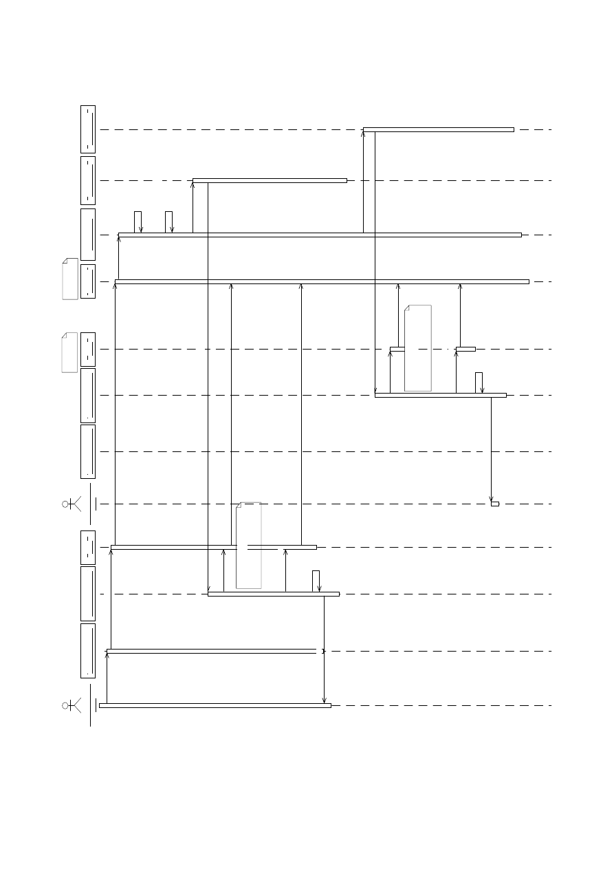
SODQ(GLWRU
3ODQ
(GLWRU
EUHDN3ODQQHU9LHZ
%UHDN3ODQQHU9LHZ
EUHDN3ODQQHU9LHZ
%UHDN3ODQQHU9LHZ
VWDWLVWLFV9LHZ,PSO
6WDWLVWLFV9LHZ,PSO
VWDWLVWLFV9LHZ,PSO
6WDWLVWLFV9LHZ,PSO
EUHDN
%UHDN
EUHDN,PSO
%UHDN,PSO
EUHDN
%UHDN
RUJDQL]HU
2UJDQL]HU,PSO
VWDWLVWLFV9LHZ
6WDWLVWLFV9LHZ
VWDWLVWLFV9LHZ
6WDWLVWLFV9LHZ
SODQ(GLWRU
3ODQ
(GLWRU
DVVLJQ
EUHDN
WR
WHDFKHU
DVVLJQ7HDFKHU
DVVLJQ7HDFKHU
VHW&KDQJHG$QG1RWLI\
6HUYHU 6LGH
&OLHQW 6LGH
VHW&KDQJHG
QRWLI\2EVHUYHUV
XSGDWH
XSGDWH
LV2FFXSLHG
LV2FFXSLHG
KDV&RQIOLFW
KDV&RQIOLFW
XSGDWH
XSGDWH
LV2FFXSLHG
LV2FFXSLHG
KDV&RQIOLFW
KDV&RQIOLFW
UHGUDZ
UHGUDZ
UHFRJQL]H
FKDQJHV
PRUH
PHVVDJHV
UHWULHYLQJ
DOO
LQIRUPDWLRQ
WR
VKRZ
DFWXDO
EUHDN
VWDWLVWLFV
UHFRJQL]H
FKDQJHV
PRUH
PHVVDJHV
UHWULHYLQJ
DOO
LQIRUPDWLRQ
WR
VKRZ
DFWXDO
EUHDN
VWDWLVWLFV
Figure 15: Sequence Diagram Showing the Communication via RMI
39

the selection was more or less trivial because Java's datatypes were sucient for our needs.
The datatypes chosen can be seen in the class diagram of Figure 5.2.2 on page 37.
6.2 Implementation of Associations
There exist many possibilities for the implementation of associations. Some of them are:
Reference attributes or|in the case of 1-to-n- or m-to-n-associations|containers
with references can be embedded into the associated classes. If the association must
be bidirectional, both concerned classes have to be adapted, and the consistency of
the two directions has to be ensured. Most of our associations follow this implemen-
tation scheme. An example is the 1-to-n-association
supervises
between
TeacherImpl
and
BreakImpl
. It is implemented by the attribute
BreakImpl::duty : TeacherImpl
and
by the attribute
TeacherImpl::duties : Vector
.
Associations can be implemented by a dedicated association class containing refer-
ences to the associated objects. We did not use this implementation scheme because
its only advantage|the possibility to store the association instances between all ob-
jects in a container and enumerate them quickly|was of no use in our application.
Associations to a singleton class can be implemented by an \implicit class reference"
in Java. An example for this is the association between
OrganizerImpl
and
StaImpl
:
StaImpl
could be given a static variable
theStaImpl
that is instantiated once dur-
ing the initialization of class
StaImpl
. This would make it possible to access this
variable's object with the Java idiom
StaImpl.theSta
in the code of other classes.
However, we decided not to use this idiom because it does not restrict the access to
the singleton instance for other classes importing the package.
6.3 Separation of Client and Server Functionality
As explained in the previous section, we have restricted the client's view onto the server's
functionality by including only a subset of the server class operations into the client
interfaces. This approach has the problem that the server needs to cast objects from
interface types to server types in order to use the additional server functionality, as can
be seen from the following example: Imagine that the client wants to assign a teacher
to a break by calling
Break::assignTeacher(t)
where the parameter
t
is of type
Teacher
. If
Break::assignTeacher(t)
now wants to call
t.addDuty()
, it must rst cast
t
to type
Teacher-
Impl
.
To clearly separate these potentially unsafe casts in our code, we have provided dierent,
but semantically equal methods for each operation that is accessible for the client as well
as for the server:
Server Methods
are declared only in the server implementation classes and implement
the functionality of the method. Their signatures contain only implementation class
types (the ones suxed by \Impl"). To distinguish these methods from the client
methods, their names are prexed with the letter `
i
' (for
i
mplementation).
Client Methods
are declared in the client interface and implemented in the server im-
plementation class. They provide no own functionality, but serve only as a wrapper
40

for the server methods. Their signatures contain only interface types. Client meth-
ods have a very simple, schematic implementation consisting of the following actions:
Find the corresponding implementation object for the remote reference parame-
ter (this step is described in more detail in section 7.9, paragraph \RMI Coerce
Workaround").
Cast down the types of all actual parameters from remote client interface types
to server implementation types.
Call the corresponding server method.
Cast up the type of the result parameter|provided one exists|to a remote
client interface type.
Apart from the gained clarity of the implementation, this scheme has the advantage
that the server functionality can be easily tested stand-alone by considering only server
methods. If the server is stable enough, one can then deal with the additional issues
introduced by distribution. Another advantage is the improved performance: Once the
translation to server objects has been done by the client method, all its method calls
to the parameter objects on the server run locally and do not involve stubs or remote
references.
6.4 Packaging of Java Source Code
In Java, packages contain a group of classes logically related to each other. Operations,
attributes, and whole classes can be hidden from other classes or other packages. Packages
can import other packages that contain needed functionality. These concepts can be
modeled with the UML package concept, as can be seen in Figure 16, which shows the
four packages of the break planner application as well as the
import
relations between
them.
Note that the client does not import the package
breakplanner.server
with the implemen-
tation classes for the system's remote objects.
6.5 Implementation of Method Bodies
The implementation of the method bodies is the last step towards a working program.
In our case, most of the methods have trivial implementations, apart from some slightly
more complex ones like
TeacherImpl::dutiesWithConict
. The source code of the system
can be found in [RS97].
7 Comments
The comments in the following sections do not cover all aspects of UML or Java. Most of
them are motivated by concrete problems with these techniques during the development
of the break planner application.
41
breakplanner.server
+ TeacherImpl
+ BreakPlanImpl
+ BreakImpl
+ PeriodImpl
+ StaffImpl
+ OrganizerImpl
+ ExclusionTimeImpl
+ BreakPlanner
breakplanner.api
+ Staff
+ Teacher
+ ExclusionTime
+ Break
+ BreakPlan
+ Organizer
breakplanner.client
+ BreakPlannerView
+ StatisticsView
COM.cariboulake.util
+ RemoteObserver
+ RemoteObservableImpl
+ RemoteObservable
<<imports>>
<<imports>>
<<imports>>
<<imports>>
Figure 16: The Package Structure of the Implementation
7.1 Use Case Diagrams
Seen as an isolated description technique, use case diagrams are not a very powerful
formalism: They contain not very much information about the functionality of a system,
but are used mainly as a structuring aid for other kinds of diagrams. On the other
hand, they can be easily understood by customers, and they are very useful for early
requirements analysis because they enforce the identication of the dierent users and
uses of a system.
In the so-called \semantics denition" of [BRJ97], it is \the responsibility" of a use case
to \specify a set of use case instances, where a use case instance represents a sequence
of actions a system performs that yields an observable result of value to a particular
actor" (`actor' means `user' in our context). The action sequences of a use case may be
described and specied by means of other description techniques like sequence diagrams,
collaboration diagrams, and activity diagrams.
In the meta-model provided by the UML authors the concept of a use case is derived
from the \Type" concept. A somewhat strange eect of this derivation is that use cases
inherit some properties that we can not make sense of. As expressed in section 7 of the
semantics document [BRJ97], they have attributes and operations, but it is not explained
what these attributes and operations should be|in our eyes their presence conicts with
the semantical denition of a use case as a set of action sequences.
Another unclear point concerns the semantics of the
uses
and
extends
-relations.
Apart from informal descriptions, where both relations are equally described as a sort of
\inclusion" or \extension", the UML 1.0 semantic denition documents provide no useful
information on this issue.
A possible interpretation of
A
uses
B
is given by the following conditions, following
42

Coleman [Col97]:
A
incorporates
B
as a sub-ow of events. It must be specied where
B
is inserted.
The details of use case
B
are hidden from
A
.
B
is a fully edged use case and may involve some or all of
A
's connections.
With respect to the corresponding sequences, this can be interpreted as: One or more
sequences of
A
's sequence set contain sequences of
B
's sequence set as contiguous sub-
sequences at certain locations in time. Note that although this situation very much
resembles a procedure call in programming languages, one cannot assume the presence of
a \runtime connection" or a procedure call between two use cases because use cases are
only conceptual modeling constructs usually not directly implemented in a system.
In contrast to this, the situation
B
extends
A
can be dened by other conditions, again
following [Col97]:
Two use cases are dened:
A
and
A extended by B
.
B
is a variation of
A
. It contains additional events (e.g. for a failure or to deal with
an extra complexity) for certain conditions.
It has to be specied where
B
is inserted in
A
.
B
is not a fully edged use case.
With respect to the corresponding sequences, this can be interpreted as:
B
contains all
action sequences of
A
and furthermore adds own sequences that contain sequences of
A
as (possibly non-contiguous) subsequences.
Other questions left open by [BRJ97] are:
Is it possible to have a use case without a connection to a user?
Such a use case would in some way contradict with the purpose of a use case as
a modeling concept for the usage of a system by users, but could be handy for
modeling internal system tasks that can be handled automatically and do not need
human interaction.
If a use case
A
is extended by a use case
B
, does
A
have to be connected with all
users of
B
? And does
B
have to be connected with all users of
A
?
We think the answer to both of these questions is negative, considering the example of
a hypothetical use case
Edit Data
extended by
Edit Condential Data
, which contains
additional functionality for authorization. In this example, there may well be (classes
of) users associated exclusively with only one of these use cases.
If a use case
A
is extended by a use case
B
, must
B
have
uses
-connections to the
same use cases as
A
?
According to the sequence interpretation of use cases given above, the answer must
be yes. However, it is the question whether such obligatory and, therefore, redundant
connections should be represented in a use case diagram. Our recommendation is to
draw them only if the extended use case introduces own functionality that
uses
the
concerning use case also, and to leave them out otherwise.
In our opinion, use cases should have a stronger connection to class diagrams. We have
therefore included in the dictionary entry of each use case a
Data
-line containing the
43

classes concerned by the use case (see Section 4.1.2). By comparing the actions of the use
case with the attributes and operations of the classes, one can check whether the classes
contain all functionality needed (and not more than needed) and get hints about what
data is shared among which users. A better way to visualize the correlation between
classes and use cases could be provided by a tool that highlights the classes belonging to
a certain use case in the class diagram.
In total, we think that UML use cases are a valuable tool for requirements analysis. A
clear denition of their syntax and semantics seems to be possible, but is missing in
[BRJ97].
7.2 Class Diagrams
Semantics of Associations
Although class diagrams are a well-known formalism
in many object-oriented development methods, their semantics is not totally clear with
respect to associations. We have explained some possibilities for the translation into code
in Section 6.2.
Boundary Concept
Class diagrams as used in UML lack the concept of a system
scope, making it hard to distinguish entities that must be implemented from entities in
the environment of the system. This is in general true for all description techniques of
UML except for use case diagrams where this boundary is represented by the rectangle
enclosing the use case ellipses. The addition of a system boundary concept, as e.g. in
Fusion [CAB
+
94], would ll this gap.
Instance Diagrams
In general, class diagrams do not constrain the possible object
graphs that may occur during the runtime of a program. However, for the special case of
the class diagram in Figure 8 with its two singleton classes and its tree-like aggregation
structures, all object graphs allowed by the class diagram are admissible, so that additional
description techniques are not necessary.
We have not included an instance diagram because it would have been very large even
for a small example with only a few breaks and teachers. In order to comprehend the
tangled object graphs that arise in the context of more complex class diagrams, more
powerful description and specication formalisms than instance diagrams are needed, like,
for example, component diagrams as introduced in [Ber97].
Renement
As described in Section 5.1, the essential step in system design is to
construct a detailed, rened class diagram from the analysis class diagram. Although
UML contains notations to represent renement steps, we could not use them in our
model:
The proposed notation for \renement within a given model" would have led to a huge,
incomprehensible model containing all the classes of the dierent development phases
together with their renement relations (see [BRJ97], Notation Guide, Section 4.26, and
left side of Figure 17). In our opinion, this variant should be restricted to the special case
that one wants to demonstrate the renement of a single entity explicitly.
The notation for \renement between models" is based on \an invisible hyperlink sup-
ported by a dynamic tool" and is, therefore, not a suitable notation for a paper-based
44
presentation. We think that a simple and general notation for the representation of rene-
ment relations between models should be introduced that is usable also for a paper-based
presentation. We propose the use of a special symbol for this purpose, reminiscent of a
back-reference as well as of a generalization arrowhead (see right side of Figure 17).
StringSet
VectorStringSet
<<type>>
StringSet
VectorStringSet
Figure 17: Representation of Renement Within and Between Models
The semantics of renement relations is left entirely open in UML|there are no rules
clarifying which renement steps exist and when they can be applied. A more formal
treatment would allow the implementation of tools that support or maybe even automate
the execution and validation of renement steps. Some examples for possible renement
steps are contained in sections 5.1.1 and 5.2.2 for class diagrams, and in sections 5.1.3
and 5.2.2 for sequence diagrams.
Responsibilities
UML lacks a notational construct for grouping attributes and oper-
ations of a single class together into so-called \responsibilities", a concept introduced by
Wirfs-Brock [WBWW90].
We propose to use a simple, tree-like notation, where responsibilities are represented in
bold font above the indented names of their contained elements (see Figure 18). A tool
could then be used for switching between folded and unfolded views.
mName : String
mJob : float
mDuties : Vector
mStaff : Staff
addExclusionTime()
removeExclusionTime()
countExclusionTimes()
getExclusionTimes()
addDuty()
removeDuty()
countDuties()
getDuties()
neededDuties()
dutiesWithConflict()
exclusionTimesWithConflict()
getJob()
setJob()
getName()
setName()
getStaff()
[manages n Duty]
setStaff()
mExclusionTimes : Vector
Teacher
Teacher
mJob : float
dutiesWithConflict()
exclusionTimesWithConflict()
+name
-Associations
+exclusionTimes
+staff
-job
-Data
-Functionality
-supervises
void addDuty(Duty)
void removeDuty(Duty)
Enumeration getDuties()
int countDuties()
[readwrite float]
float getJob()
setJob(float)
Figure 18: Grouping of Class Features with Responsibilities
Even in the context of relatively small class diagrams like the ones of the break planner, re-
sponsibilites would allow to comprehend the structure of classes with many features much
faster. The use of equally named responsibilities in dierent classes could furthermore
help in understanding mechanisms implemented by collaborating classes. An example
45

would be the use of
MVC
responsibilities, grouping together the collaborating operations
in various model, view and controller classes.
Responsibilities can rst be introduced during requirements analysis to specify the data
and functionality of a class informally, leaving open the nal names and signatures of
its operations and attributes. During design and implementation, responsibilities can
then be rened stepwise by adding attributes, operations, and also other responsibilities.
Specialized documentation tools like
javadoc
[SUN97a] could also use responsibilities to
present class features in a structured way.
Another possibility is the use of standardized responsibility schemes that could be un-
folded automatically with the help of a tool. This would for example be useful for the
handling of associations or data attributes, where the same patterns of attributes and ac-
cess operations appear over and over again in a detailed class diagram. An example for a
responsibility schema is a scalar attribute, like
job
in Figure 18: It is usually implemented
by the attribute itself and two access methods
getJob
and
setJob
for reading/writing the
attribute's value. Another example are managed 1-to-n associations like
supervises
that
are usually implemented by a special pattern of operations (cf. section 5.1.4).
Interfaces
According to UML, an interface should be represented as a little, named
circle next to the class implementing the interface. The advantage of this notation is that it
needs less diagram space and fewer lines in comparison to a class-like representation. The
disadvantage is that one can not see the operations of an interface in the class diagram.
There is also no notation for representing subtype relations between interfaces.
The notation should therefore only be used for standard interfaces with known functional-
ity that are not subtyped. A good example in the context of Java is the standard interface
Serializable
. However, we have not used this notation in the class diagrams of Figures 10
and 5.2.2 because our tool did not provide it (cf. Section 7.10).
If the operations of an interface are important or an interface is subtyped|for example in
the case of the observer interface in Figure 10 or all remote interfaces in Figure 5.2.2|,
we recommend to use a class-like notation where interfaces are marked with the special
stereotype
Interface
.
However, one should not assume that all interfaces are Java interfaces: Sometimes one
only wants to denote a certain subset of the functionality of a class as an interface. In this
case no interface type exists, and the class-like notation would thus be misleading. For
this purpose, we propose to use a special kind of a responsibility containing the specier
Interface
in its name.
7.3 Sequence Diagrams
Sequence diagrams show exemplary interactions between objects. They emphasize the
time dimension and contain the association links between the objects only implicitly.
It is out of question that sequence diagrams are a useful description technique: In our ex-
perience, they are|together with class diagrams|the predominant description technique
in design meetings. Furthermore, sequence diagrams can be given a precise semantic, as
is for example shown in [BHKS97].
UML enhances sequence diagrams with a notation for modeling the message ow between
46

\entire sets of objects" instead only between single objects. It is however not clear what
the semantics of this construct is|is a message related to all or only some of the objects
in the set? If the latter is true, how is the subset specied?
Sequence diagrams could be used as test cases for an existing implementation of a sys-
tem. For this purpose, additional information like preconditions, input data, and test
instructions should be provided for sequence diagrams, and there should be methodical
guidelines on the usage of sequence diagrams for testing.
In addition to \exemplary" sequence diagrams, the UML variant contains features like
conditional subsequences that make sequence diagrams useful also for the specication
of behavior. However, there exists no notation to discern sequence diagrams meant as
comprehensive specications of all possible interactions from sequence diagrams showing
just exemplary interactions. It is also not clear for which object congurations a se-
quence diagram specication is valid|does the sequence diagram imply that only certain
congurations appear during the runtime of a system or does it apply only in certain
situations?
7.4 Collaboration Diagrams
Collaboration diagrams resemble sequence diagrams in most respects. However they em-
phasize the relationships between objects and show the ow of time only implicitly using
sequence numbers.
An automatic translation between sequence diagrams and collaboration diagrams is, there-
fore, possible with one exception: Connections not used for communication can only be
represented in collaboration diagrams. Apart from this rather unimportant issue, it seems
just a matter of personal style which of both techniques one wants to use.
The authors of [BRJ97] also propose the usage of \before-after conditions" for declarative
specications of the behavior of a type's instances. However, it is left totally unclear
how this formalism is related to the other description techniques for the specication of
a system's dynamics, what formalisms are admissible in before-after conditions, and how
the \context" of a type should be dened. We have, therefore, not included a collaboration
diagram for the types of the break planner application.
Another collaboration notation is used for design patterns which would otherwise not be
visible in a class diagram. This notation has proved valuable to describe the presence of
the observer pattern in our application (see Section 5.1.3). Yet, it is doubtful whether
more complex design patterns could be integrated into a class diagram equally simple|
the dierent components of the microkernel pattern in [BMR
+
96] represent, for example,
rather subsystems than classes, so that mapping them to simple classes makes no sense.
7.5 State Diagrams
State transition diagrams are a universal and well-known formalism for specifying the
state space and the state transition relation of entities. However, most questions about
their methodical use and about their semantics in the context of object-oriented modeling
are left open in the UML specication. Consistency criteria and methodical guidelines
for the simultaneous use and the transition between activity diagrams, state diagrams,
sequence diagrams, and collaboration diagrams are urgently needed.
47

A similar problem concerns the consistency between dierent, but related documents of
a single dynamic description technique. Classes related by inheritance should inherit not
only attributes and operation signatures, but also dynamic behavior as specied by the
class state diagrams of their base classes [Rum96], and rened versions of classes should
have a suitably rened behavior. Also needed is the possibility to assign a state diagram
to a compound component and to break it down into subordinate state diagrams.
7.6 Activity Diagrams
As mentioned in Section 2.1, activity diagrams can be used on dierent levels of abstrac-
tion. In our project, we have used them for business process modeling (see Sections 4.1.4
and 4.1.6) as well as for specifying the behavior of single operations (see Section 5.1.5).
Although the use of activity diagrams for business process modeling during the analysis
phase seems like a simple and natural concept, their implementation and translation to
source code is not trivial. In principle, the following possibilities exist:
Explicit Control:
Activity diagrams serve as an explicit, operational specication for a
specialized workow engine controling the functionality of components of a system.
Using a workow engine seems to become a common architecture for the integration
of legacy components (which may be also whole programs) into a larger system.
Implicit Control:
Activity diagrams serve as a specication for the interaction of com-
ponents. This approach is common with user interfaces, where the control ow will
likely not be implemented by a centralized workow component, but will be inte-
grated in the callbacks and operations of the GUI classes. When used to specify the
interactions of GUI elements, activity diagrams resemble the so-called \interaction
diagrams" of Denert [Den91].
To facilitate the translation to source code or to even allow an automated implementation
via tools, the semantics of activity diagrams must be clearly dened. This would also help
the user to understand the connection between action states and actual programs or GUI
prototypes.
Another critical point is the lack of methodical guidance for the transition from exemplary
sequence diagrams to prescriptive activity diagrams: In general, it is not trivial to identify
the common characteristics of a set of possible sequences and to build suitable activity
diagrams that allow all these sequences. This is particularly dicult because a single
action sequence can in principle be the result of the interleaved execution of more than
one use case.
UML states that an activity diagram is \a special form of a state diagram". As such, it
should use the syntactical constructs introduced in the section on state diagrams. How-
ever, that seems not to be the case with so-called \complex transitions", especially when
the \swimlane" notation is used. First, there is a minor inconsistency in Figure 50 of
[BRJ97]: Complex transitions are represented there by short heavy horizontal bars in-
stead of short heavy vertical bars, as specied in section 8.6.2. Second, the diagram in
Figure 53 of [BRJ97] (see Figure 19) contains action states like
Pay
and
Take order
in
swimlane
Sales
that are meant to run concurrently, but it does not have any complex
transition. The correct representation should resemble the activity diagram of Figure 6
in this respect.
48
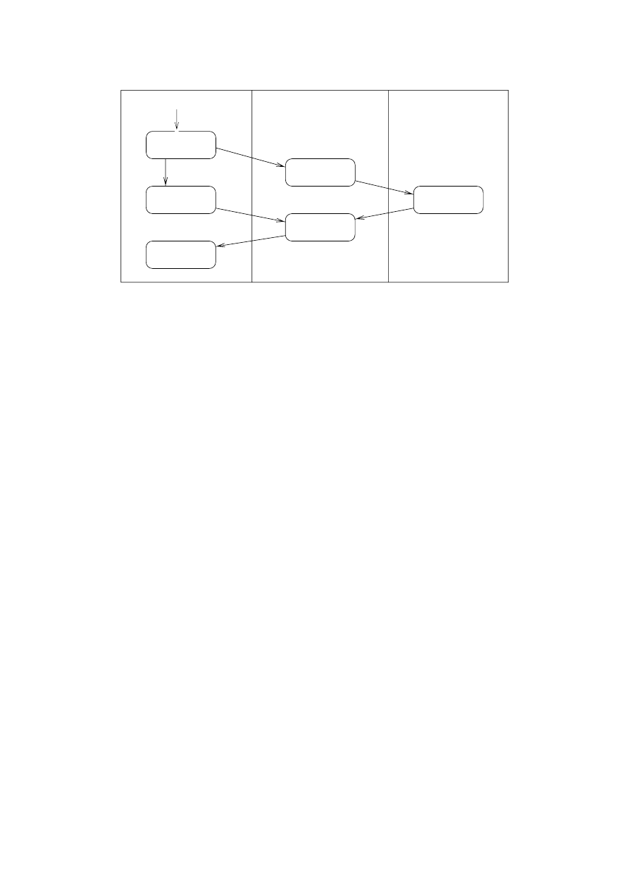
Customer
Request service
Sales
Stockroom
Pay
Take order
Fill order
Deliver order
Take order
Figure 19: Activity Diagram with Concurrent States of [BRJ97]
Although activity diagrams are intended to specify the dynamic behavior of a system,
they can not deal with changing object graphs properly: This can be seen from diagram
13: It contains two swimlanes, namely
Break
and
Teacher
. While the action
hasConict
belongs to a special, single object, the action
overlaps
is executed for all instances of
Break
that are connected to its supervising
Teacher
object. However, there is no notation to
discern actions concerning a single object from actions concerning a whole set of objects
in the same swimlane.
During design, activity diagrams can be used to specify the control ow of methods.
When used for this purpose, they are very similar to well-known techniques like Nassi-
Shneidermann charts or owcharts. However, most operations in object-oriented programs
are very simple and creating an activity diagram for them would not introduce additional
clarity.
7.7 Implementation Diagrams
There exist two forms of implementation diagrams: Component diagrams model the dis-
tribution of object instances at runtime, while deployment diagrams model the location
of the object code. These two views are isomorphic only in the special case that each
object instance has its own program code.
However, UML seems to neglect the dierence between component and deployment dia-
grams and allows combined diagrams containing both aspects. This is shown in Figure
20, which contains Figures 56 and 57 of [BRJ97]: The component diagram on the right
contains the program component
Scheduler
that accesses the component instance
meet-
ingsDB
.
The notation provided seems also overly simple. It does, for example, not contain concepts
for inheritance and recursive containment of component instances, and it allows only
the representation of static congurations consisting of a xed number of hard-wired
component instances. To overcome these limitations, more powerful formalisms like the
one proposed in [Ber97] are needed.
Finally, UML says nothing about the relation of implementation diagrams to the other
49
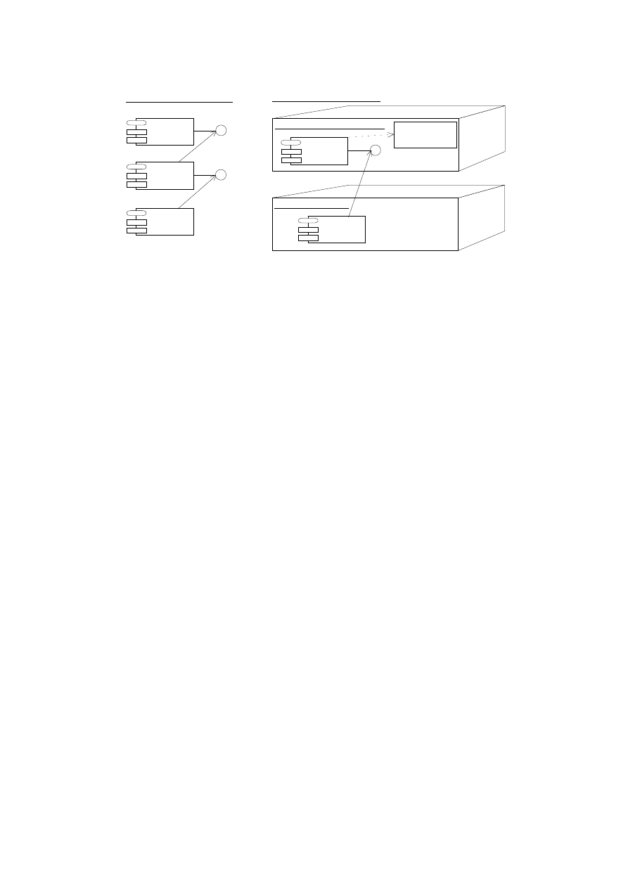
Scheduler
Planner
Component Diagram:
reservations
update
GUI
Deployment Diagram:
AdminServer:HostMachine
<<database>>
meetingsDB
reservations
Scheduler
Joe's Machine:PC
Planner
Figure 20: Component and Deployment Diagrams in [BRJ97]
description techniques. This would be necessary especially for instance diagrams, sequence
diagrams, and collaboration diagrams because these diagrams also refer to object and
component runtime congurations.
7.8 User Interface Prototype
The decision to build a GUI prototype of an application may have three (classical) reasons:
1. The look-&-feel of the nal system can be demonstrated and the adequacy of the
user interface can be evaluated (explorative prototyping).
2. Experience with a concrete implementation technique can be gained in the context
of a small, manageable system (experimental prototyping).
3. The code of the prototype can be reused in the nal system (evolutionary prototyp-
ing
).
We think that we could achieve the rst two goals reasonably well. The demonstrated
look-&-feel seems acceptable, although the lack of a drag-&-drop mechanism in Java 1.0.2
complicates the interaction with the program. The experiences of Klaus Berg and Briktius
Marek with Visual Cafe [Sym97] were quite positive. We can not comment on the third
point because the integration of the GUI prototype with the rest of the system has not
started yet.
To build a GUI prototype, one should at least have the information from a rst use case
analysis. Especially the information about usage frequency and the experience level of the
users (cf. Sections 4.1.2 and 4.1.3) can provide hints for the design of the user interface
and the help system.
Besides the `look' of a program's screen layout, a user interface prototype also demon-
strates the `feel' of the interaction. This includes dynamic aspects, e.g. the navigation
between the dialog elements, the creation or deletion of windows, and the enabling or dis-
abling of input elds. Although these aspects can be described by sequence diagrams and
activity diagrams, detailed models of user interfaces would be large and dicult to un-
derstand, especially compared to the very intuitive experimentation with the prototype.
On the other side, a prototype can also mislead the user because it may, for example,
simulate response times that can not be met by the nal system.
50

Our recommendation is, therefore, to model at least all important dynamic aspects that
can not be simulated with a user interface prototype by means of other, more formal
description techniques. We have done so with the update of the break statistics in Section
4.1.5.
7.9 Java, Object Serialization and Remote Method Invoca-
tion
During the implementation process we encountered a couple of problems with Sun's JDK
[SUN97b]:
Singleton Gripe
The singleton characteristics of a class is not supported by Java. We,
therefore, implemented our own mechanism to make sure that always exactly one
instance of the classes
Sta
and
Organizer
exists. We use a newly introduced excep-
tion called
SingletonException
signaling attempts to create more than one instance
of these classes.
Serialization of Static Attributes
Object serialization supports the encoding of com-
plete object graphs into a stream of bytes and vice versa. However, references
contained in static attributes are ignored and must thus be handled separately.
RMI Coerce Workaround
If a client sends the server a reference to one of the server's
own remote objects, the server can not typecast that reference to the corresponding
implementation object. The reason for that is that the server does not get a local
reference, but instead a reference to a stub object that accesses the \real" implemen-
tation object via a skeleton. To invoke server-only methods|methods not contained
in one of the remote interfaces accessible to the clients|, one has to maintain a ta-
ble with this relation on the server. In our implementation [RS97], we use the extra
class
InterfImplHandler
for that purpose.
Remote Observer Obstacle
During the implementation phase we found ourselves un-
able to combine Java's observer mechanism with the RMI concept. Neither inher-
itance nor wrapper-based techniques make it possible to create a remote observer
mechanism on top of Java's standard observer classes. The only remaining solution
is a total re-implementation of the needed functionality. Fortunately, we did not
have to do this by ourselves because we could use a free implementation provided
by Caribou Lake Software (see [Car97]).
Remote Object Inheritance
RMI Objects are made remote by inheriting from the
class
RemoteObject
. This forces the programmer to make all classes in a hierarchy
remote if actually only one class is intended to be remote. Although this was no
problem for our application, \disinheriting" non-remote classes from remote ones
during distribution design could necessitate extensive transformations of the class
hierarchy and the corresponding algorithms.
7.10 Tool Support
We used the tool Rational Rose 4.0 for the creation of most of our diagrams, as it was
one of the rst CASE tools to support the UML notation. Rational Rose 4.0 can be
downloaded from Rational's Homepage [Rat97] in a demo version for the language C++ on
51

the Windows 95 platform. The tool supports a broad selection of the notations proposed
in the UML documents, but has also some aws:
Static Structure Diagrams
Class diagrams in Rose lack some features like the circle
notation for interfaces and the various presentation options for aggregations.
Use Case Diagrams:
Use case diagrams are well supported by the tool. However, Rose
does not allow to draw the system boundary box around the use cases.
Sequence Diagrams:
Rose lacks UML's notation for creation and deletion of objects.
Collaboration Diagrams:
The collaboration diagram in Figure 11 has been drawn only
partly using Rose because the tool cannot show the occurrence of a design pattern
in a class diagram. In addition, specifying a collaboration for a type, like introduced
in section 7.3.3 of [BRJ97], is not possible.
State Diagrams:
With the exception of concurrent states, state diagrams are well sup-
ported.
Activity Diagrams:
Simple activity diagrams can be drawn. Concurrent states, deci-
sions and swimlanes are missing.
Implementation Diagrams:
Neither component diagrams nor deployment diagrams as
specied by [BRJ97] can be created using the current version of Rose. The supported
implementation diagrams are quite dubious: On the one hand some basic elements
like interfaces and nodes are missing, on the other hand additional elements like
tasks or processors are available.
8 Conclusion
In this paper we have provided an example for the development of a distributed Java
program using UML 1.0. We have described the development process we followed and the
design decisions we have made, as well as the diculties we have encountered.
All in all our experiences with UML were not totally negative|we could overcome all
problems and were able to model most aspects of the break planner system. However,
this does not imply that UML is a mature modeling language that can be used for real
projects without problems. Our main criticisms are:
UML provides a wealth of description techniques, but denes neither their syntax
nor their semantics precisely and unambiguously. This makes modeling sometimes
deceptively easy because one is allowed to draw all kinds of diagrams that have no
useful meaning for the subsequent implementation.
The missing semantic foundation is also problematic with respect to the relationships
between the various development documents, especially when it comes to describ-
ing the dynamic behavior of a system: Because there exist no consistency criteria
between description techniques it is hard to check whether all of their requirements
can be combined and fullled by the implementation. Consistency criteria and me-
thodical guidelines could also make the production of development documents easier
because they restrict the possibilities of the developers and force them to consider
only meaningful diagrams.
52

The same considerations apply to UML's concept of renement|it is not dened
when a development document is a rened version of another document and what
development steps are admissible for rening documents.
UML's description techniques cannot deal suciently with complex, changing ob-
ject graphs and hierarchical composite objects. The existing notations for so-called
\multi-objects" in sequence and collaboration diagrams seem very ad-hoc and leave
many questions open, as well as the whole description technique of component dia-
grams.
UML lacks abstraction techniqes for large class diagrams with many attributes and
operations.
Some of the techniques of UML aim at the implementation of a CASE tool and can-
not be presented on paper. An example are most relationships between development
documents which shall be represented by \invisible hyperlinks" according to UML's
denition.
The UML Notation Guide and the UML Semantics Document [BRJ97] do not con-
tain contain sucient examples and are not very readable, if not to say confusing.
This is especially true for the Semantics Document: Large parts of it seem to be
machine-generated English, the index is nearly unusable because it contains too
many references for each entry, and the denitions contained are informal and un-
clear.
Our valuation of Java is more positive. The main problems we encountered concerned the
RMI mechanism which oers no support for the restriction of a remote client's functional-
ity. However this problem could be overcome relatively easily by a schematic workaround.
Acknowledgements
We thank Ruth Breu, Ingolf Kruger, Bernhard Rumpe, and Alexander Vilbig for interest-
ing discussions and comments on earlier versions of this report. We are especially indebted
to Ingolf Kruger who did a careful proofreading of large parts of the paper.
References
[Ber97]
Klaus Bergner. Spezikation groer Objektgeechte mit Komponentendia-
grammen
. CS Press, 1997.
[BHH
+
97] Ruth Breu, Ursula Hinkel, Christoph Hofmann, Cornel Klein, Barbara
Paech, Bernhard Rumpe, and Veronika Thurner. Towards a formaliza-
tion of the unied modeling language. TUM-I 9726, Technische Universitat
Munchen, 1997.
[BHKS97] Manfred Broy, Christoph Hofmann, Ingolf Kruger, and Monika Schmidt. A
graphical description technique for communication in software architectures.
TUM-I 9705, Technische Universitat Munchen, 1997.
[BM97]
Klaus Berg and Briktius Marek. GUI prototype for the break planner ap-
plication, 1997.
53

[BMR
+
96] F. Buschmann, R. Meunier, H. Rohnert, P. Sommerlad, and M. Stal.
Pattern-Oriented Software Architecture | A System of Patterns
. Wiley
& Sons, 1996.
[Boo94]
G. Booch. Object-Oriented Analysis and Design with Applications. Ben-
jamin/Cummings, 2 edition, 1994.
[BRJ97]
G. Booch, J. Rumbaugh, and I. Jacobson. Unied Modeling Language, Ver-
sion 1.0
. Rational Software Corporation, URL:
http:/www.rational.com
,
2800 San Tomas Expressway, Santa Clara, CA 95051-0951 (USA), 1997.
[CAB
+
94] D. Coleman, P. Arnold, S. Bodo, C. Dollin, H. Gilchrist, F. Hayes, and
P. Jeremes. Object-Oriented Development | The Fusion Method. Prentice
Hall, 1994.
[Car97]
Caribou Lake Software. Remote Observer Classes,
http://www.cariboula
ke.com/utils.html
, 1997.
[Che76]
P. P. S. Chen. The entity-relationship model | toward a unied view of
data. ACM Transactions on Database Systems, 1(1), 1976.
[Col97]
Coleman. Slides on uml use case modeling, 1997.
[DAC]
DACH Group. Universitat Hamburg, FB Informatik, AB Softwaretechnik;
Johannes-Kepler-Universitat, Linz, Austria, Institut fur Wirtschaftsinfor-
matik, Doppler-Labor fur Software Engineering; GMD Bonn, Schlo Bir-
linghoven, St. Augustin; UBS Information Technology Laboratory, Zurich,
Switzerland.
[Den91]
E. Denert. Software Engineering. Springer-Verlag, 1991.
[Fla96]
D. Flanagan. Java in a Nutshell. O'Reilly & Associates, Inc., 1996.
[GHJV95] E. Gamma, R. Helm, R. Johnson, and J. Vlissides. Design Patterns: Ele-
ments of Reusable Object-Oriented Software
. Addison-Wesley, 1995.
[IT93]
ITU-TS. ITU-TS Recommendation Z.120: Message Sequence Chart (MSC).
ITU-TS, Geneva, September 1993.
[Jac92]
I. Jacobson. Object-Oriented Software Engineering | A Use Case Driven
Approach
. Addison-Wesley, 1992.
[Jav95]
JavaSoft, A Sun Microsystems, Inc. Business.
http://java.sun.com
, 1995.
[Jav97]
Java security { frequently asked questions, 1997.
[LRH97]
Stefan Loidl, Ekkart Rudolph, and Ursula Hinkel. Msc'96 and beyond { a
critical look. In A. Cavalli A. Sarma, editor, SDL Forum 97. Elsevier, 1997.
[Rat97]
Rational. Rational Rose 4.0 Demo,
http://www.rational.com/demos
,
1997.
[RBP
+
91] J. Rumbaugh, M. Blaha, W. Premerlani, F. Eddy, and W. Lorensen. Object-
Oriented Modeling and Design
. Prentice Hall, 1991.
[RS97]
Andreas Rausch and Marc Sihling. Source code for the break plan-
ner application backend,
http://www.forsoft.de/interna/projekte/a1
/fallstudien/bp.tar.gz
, 1997.
[RSLML96] S. Roock, K.-H. Sylla, C. Lilienthal, and A. Muller-Lohmann. Der
Pausenplaner { Szenario, CRC-Karten, Systemvision,
http://set.gmd.de/
~sylla/dachpap-aufgabe.html
, 1996.
54

[Rum96]
Bernhard Rumpe. Formale Methodik des Entwurfs verteilter objektorien-
tierter Systeme
. Tum doktorarbeit, Technische Universitat Munchen, 1996.
[SCB95]
Patricia S. Bilow Steven Craig Bilow. Distributed systems design. In OOP-
SLA'95, Addendum to the Proceedings
. ACM Order Department, 1995.
[SHB96]
Bernhard Schatz, Heinrich Hussmann, and Manfred Broy. Graphical de-
velopment of consistent system specications. In James Woodcock Marie-
Claude Gaudel, editor, FME'96: Industrial Benet and Advances In Formal
Methods
, pages 248{267. Springer, 1996. Lecture Notes in Computer Science
1051.
[SM88]
S. Shlaer and S. J. Mellor. Object-Oriented Systems Analysis. Prentice Hall,
1988.
[SUN97a] SUN Microsystems. javadoc { the Java API Documentation Gen-
erator,
http://java.sun.com/products/jdk/1.1/docs/tooldocs/win32
/javadoc.html
, 1997.
[SUN97b] SUN Microsystems. The JDK 1.1.2 Documentation,
http://java.sun.com
/products/jdk/1.1/docs
, 1997.
[SUN97c] SUN Microsystems. RMI { Remote Method Invocation,
http://java.sun.
com/products/jdk/1.1/docs/guide/rmi
, 1997.
[Sym97]
Symantec. Symantec's Visual Cafe,
http://www.symantec.com/vcafe
,
1997.
[WBWW90] R. Wirfs-Brock, B. Wilkerson, and L. Wiener. Designing Object-Oriented
Software
. Prentice Hall, 1990.
55
Wyszukiwarka
Podobne podstrony:
więcej podobnych podstron