
iC- w32a
iC- w32e
INSTRUCTION MANUAL
DUAL BAND FM TRANSCEIVER
This device complies with Part 15 of the FCC rules. Operation is sub-
ject to the following two conditions: (1) This device may not cause
harmful interference, and (2) this device must accept any interference
received, including interference that may cause undesired operation.
The IC-W32E complies with the essential requirements of the
89/336/EEC directive for Electromagnetic Compatibility. This
compliance is based on conformity with the ETSI specification
prETS300 684 (EMC product standard for Commercially Avail-
able Amateur Radio Equipment).
i
CAUTIONS
R
WARNING! NEVER
hold the transceiver so that the
antenna is very close to, or touching exposed parts of the
body, especially the face or eyes, while transmitting. The
transceiver will perform best if the microphone is 5 to 10 cm
(2 to 4 in) away from the lips and the transceiver is vertical.
R
WARNING! NEVER
operate the transceiver with a
headset or other audio accessories at high volume levels.
Hearing experts advise against continuous high volume op-
eration. If you experience a ringing in your ears, reduce the
volume level or discontinue use.
NEVER
connect the transceiver to an AC outlet or to a
power source of more than 16 V DC. Such a connection will
damage the transceiver.
NEVER
connect the transceiver to a power source that is
DC fused at more than 5 A. Accidental reverse connection will
be protected by this fuse, higher fuse values will not give any
protection against such accidents and the transceiver will be
ruined.
NEVER
attempt to charge alkaline or dry cell batteries. Be-
ware that external DC power connections will charge batteries
inside the battery case. This will damage not only the battery
case but also the transceiver.
IMPORTANT
READ ALL INSTRUCTIONS
carefully and com-
pletely before using the transceiver.
SAVE THIS INSTRUCTION MANUAL —
This
instruction manual contains important operating instructions
for the IC-W32A and IC-W32E.
EXPLICIT DEFINITIONS
The explicit definitions below apply to this instruction manual.
WORD
DEFINITION
R
WARNING
Personal injury, fire hazard or electric shock
may occur.
CAUTION
Equipment damage may occur.
NOTE
If disregarded, inconvenience only. No risk
of personal injury, fire or electric shock.
ii
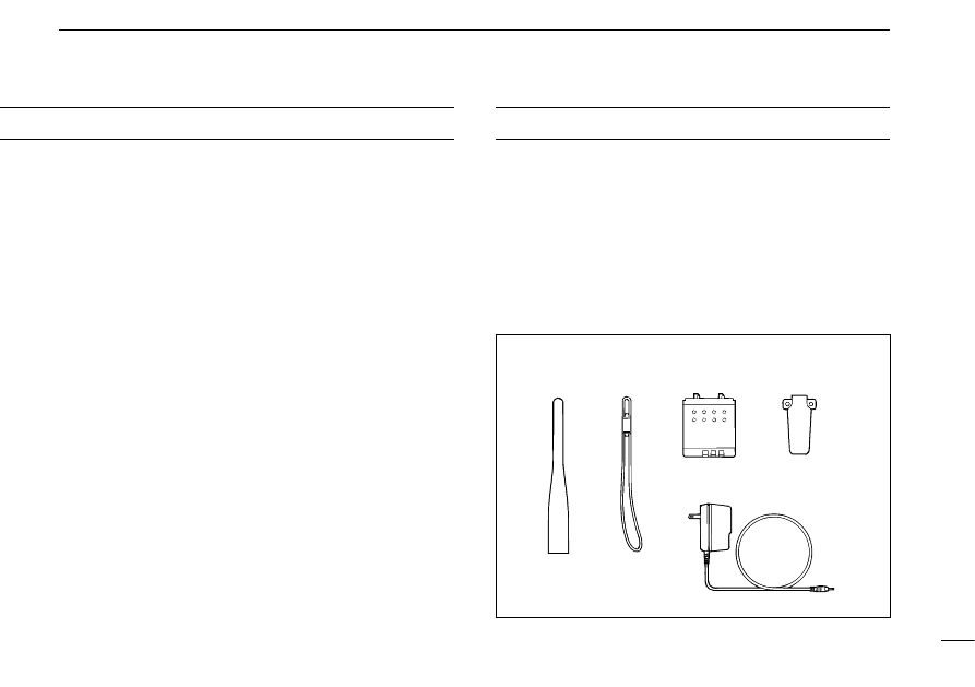
UNPACKING
Accessories included with the transceiver:
Qty.
q
Antenna ......................................................................... 1
w
Handstrap ...................................................................... 1
e
Battery pack (BP-173 or BP-180) or
battery case (BP-170) attached to the transceiver ........ 1
r
Belt clip .......................................................................... 1
t
Wall charger* ................................................................. 1
* Not supplied for some versions.
DO NOT
push the PTT when not actually desiring to trans-
mit.
DO NOT
allow children to play with any radio equipment
containing a transmitter.
DO NOT
operate the transceiver near unshielded electrical
blasting caps or in an explosive atmosphere.
AVOID
using or placing the transceiver in direct sunlight or
in areas with temperatures below –10°C (+14°F) or above
+60°C (+140°F).
The use of non-Icom battery packs/chargers may impair
transceiver performance and invalidate the warranty.
Even when the transceiver power is OFF, a slight current still
flows in the circuits. Remove the battery pack or case from
the transceiver when not using it for a long time. Otherwise,
the battery pack or installed dry cell batteries will become ex-
hausted.
q
w
e
r
t
Antenna for U.S.A. version differs from that shown above.

iii
IMPORTANT .............................................. i
EXPLICIT DEFINITIONS ........................... i
CAUTIONS ................................................. i
UNPACKING ............................................. ii
TABLE OF CONTENTS ............................ iii
1
PANEL DESCRIPTION .................. 1 – 7
■
Switches, controls, keys and
connectors ....................................... 1
■
Function display ............................... 6
2
BATTERY PACKS AND
ACCESSORIES ........................... 8 – 11
■
Battery pack charging ...................... 8
■
Charging precautions ....................... 8
■
About the battery pack ...................... 8
■
Charging connections ...................... 9
■
Battery case ................................... 10
■
Accessory attachment .................... 11
3
FREQUENCY AND CHANNEL
SETTING ................................... 12 – 16
■
Power ON ....................................... 12
■
VFO and memory/call channels ..... 12
■
Main band selection ....................... 13
■
Operating band selection ............... 13
■
Frequency or channel selection
via the keypad ................................ 14
■
Using the tuning dial ....................... 15
■
Lock function .................................. 15
■
Setting tuning dial increments ........ 16
4
BASIC OPERATION .................. 17 – 18
■
Receive and transmit ...................... 17
5
REPEATER OPERATION .......... 19 – 21
■
General .......................................... 19
■
Subaudible tones ........................... 20
■
Offset frequency ............................. 20
■
Auto repeater function .................... 21
6
MEMORY/CALL PROGRAMMING . 22 – 25
■
General .......................................... 22
■
Programming during selection ........ 22
■
Programming after selection .......... 23
■
Memory edit (transferring) .............. 23
■
Memory names .............................. 24
■
Memory clear ................................. 25
7
DTMF MEMORY ........................ 26 – 27
■
Programming a DTMF code ........... 26
■
Transmitting a DTMF code ............. 27
■
DTMF transmission speed ............. 27
8
SCAN OPERATION ................... 28 – 31
■
Scan types ..................................... 28
■
Full/programmed scan ................... 29
■
Memory scan ................................. 29
■
Skip channel setting ....................... 30
■
Scan resume condition ................... 30
■
Frequency skip function ................. 31
9
SUBAUDIBLE TONE OPERATION . 32 – 33
■
Tone squelch operation .................. 32
■
Tone scan ....................................... 33
■
Pocket beep operation .................... 33
10 OTHER FUNCTIONS ................. 34 – 38
■
Guide function ................................ 34
■
Battery voltage indication ............... 34
■
Auto power-off function ................... 35
■
Function display backlighting ......... 35
■
Power saver ................................... 36
■
LCD contrast .................................. 36
■
Optional HM-75A functions ............ 37
■
Handheld-to-handheld cloning ....... 38
■
Partial reset .................................... 38
■
All reset .......................................... 38
11 TROUBLESHOOTING ...................... 39
12 MODE ARRANGEMENT ........... 40 – 41
13 SPECIFICATIONS ............................ 42
14 OPTIONS .......................................... 43
TABLE OF CONTENTS
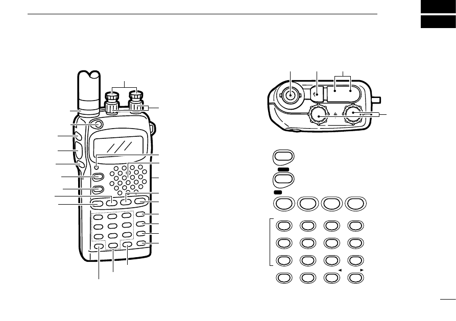
PANEL DESCRIPTION
1
1
q
Antenna
connector
w
[POWER]
o
[VFO]
y
[MAIN]
u
[BAND]
i
[MR]
e
[SQL]
r
[PTT]
t
[L/G]
!1
DIGIT KEYS
!0
[.]
!2
!3
[M•N]
!4
!5
[TONE]
!6
[H/L]
!7
[S.MW]
!8
[CALL]
!9
Battery pack
release
@0
Speaker/
microphone
@1
[TX/RX]
@2
[VOL]
@3
[DIAL]
VOL
DIAL
SP
MIC
DC13.5V
+
–
@3
q
@4
@5
■
Switches, controls, keys and connectors
BAND
CHNG
CHNG
MAIN
SCAN DTM
F
VFO
CLR
CLR
MHz
1
QZ
4
GHI
7
PRS
DTMF
•
M
•
M
MR
SKIP
CALL
LOCK
S.MW
MW
Symbol
0
M
•
N
MN
•
W
D
C
TONE
DUP
K
B
H/L
SET
J
A
2
ABC
3
DEF
5
JKL
6
MNO
8
TUV
9
WXY
T SCAN
#
!1
!0
!2
!3
!4
!5
!6
!7
!8
i
o
u
y

1
PANEL DESCRIPTION
2
y
MAIN KEY [MAIN (SCAN) (DTMF)]
➥
Push to toggle the main band assignment. (p. 13)
➥
Starts and stops a scan when pushed for 2 sec.
(p. 29)
➥
While pushing [PTT], this key transmits the se-
lected DTMF memory contents. (p. 26)
u
BAND KEY [BAND (CHNG)]
➥
Push to select the operating band (VHF, UHF,
etc.) or deactivation. (p. 13)
• For VHF display, 144 MHz band, 430(440) MHz band,
avionics band*
1
and weather channels*
2
can be se-
lected.
*
1
U.S.A. and Asia versions only
*
2
U.S.A. version only
• For UHF display, 144 and 430(440) MHz bands can be
selected.
➥
Enters the band arrangement condition to ex-
change the VHF and UHF displays when pushed
at turning power ON. (p. 13)
i
MEMORY MODE KEY [MR (SKIP)]
➥
Push to select memory mode. (p. 22)
➥
While in memory mode, push this key for 2 sec.
to toggle the selected memory channel between
a skip and non-skip channel. (p. 30)
MR
SKIP
BAND
CHNG
CHNG
MAIN
SCAN DTM
F
q
ANTENNA CONNECTOR (p. 11)
Connects the supplied antenna.
w
POWER SWITCH [POWER] (p. 12)
Push and hold for 2 sec. to toggle the transceiver power
ON and OFF.
e
SQUELCH SWITCH [SQL] (p. 17)
➥
Push to open the main band’s squelch and monitors the
operating frequency.
➥
Set the squelch level while pushing this key and rotating
the tuning dial.
r
PTT SWITCH [PTT] (p. 17)
Push and hold to transmit; release to receive.
t
LIGHT/GUIDE SWITCH [L/G]
➥
Activates the display and keypad backlighting for 5 sec.
• The backlighting can be set as manual ON/OFF, automatic
ON/OFF and automatic OFF with 5 sec. timer (default) using
initial set mode. (p. 35)
➥
Shows a quick description of a key’s function when
pushing this key and the desired key. (p. 34)
• In set mode, the quick description automatically appears when
pausing an operation for 5 sec.

1
PANEL DESCRIPTION
3
o
VFO MODE KEY [VFO (CLR) (MHz)]
➥
Push this key to cancel most functions, then push
again to select VFO mode. (p. 12)
• When making a mistake during digit input, push this
key to cancel and start from the beginning.
➥
Selects 1 MHz tuning step when pushed for 2
sec. in VFO mode. (p. 16)
➥
Partially resets the VFO frequencies, VFO set-
tings and set mode settings when pushed at turn-
ing power ON. (p. 38)
!0
DECIMAL POINT KEY [ • (DTMF•M) (
M
)]
➥
In VFO mode, push to enter the operating fre-
quency from the 100 kHz digit. (p. 14)
➥
Push this key for 2 sec. to enter DTMF memory
mode, then push again for 2 sec. to program the
DTMF memory. (p. 26)
➥
While pushing [PTT], this key sends a DTMF “E”
(
M
).
!1
DIGIT KEYS
➥
Input the specified digit during frequency input, memory
channel selection, etc.
➥
Transmit the DTMF code of the specified digit while push-
ing [PTT].
DTMF
•
M
•
M
VFO
CLR
CLR
MHz
➥
For the [1]–[5] and [0] keys, select scan edges during full/
programmed scan.
• Push [1]–[5] to select scan edges “1A/1B”–“5A/5B,” respectively.
• Push [0] to select full scan.
➥
In addition, each key has character input for memory or
DTMF memory names (characters are assigned to keys
using the same convention as for telephones). (pgs. 24, 26)
!2
TONE SCAN KEY [T SCAN (
Ω
Ω
) (#)]
➥
Push this key for 2 sec. to start the tone scan.
(p. 33)
➥
While programming memory channels or DTMF
memory names, this key moves the cursor back-
ward.
➥
While pushing [PTT], this key sends a DTMF “F”
(#).
!3
MEMORY NAME KEY [M•N (MN•W) (
≈
≈
)]
➥
Push to toggle between frequency and name in-
dications. (p. 24)
➥
While programming memory channels or DTMF
memory names, this key moves the cursor for-
ward.
➥
While pushing [PTT], this key sends a DTMF “D.”
M
•
N
MN
•
W
D
T SCAN
#

1
PANEL DESCRIPTION
4
!4
C KEY [C]
While pushing [PTT], this key sends a DTMF “C.”
!5
TONE/DUPLEX KEY [TONE (DUP) (
K
)]
➥
Push this switch to activate the following functions
in order (pgs. 19, 32).
• Subaudible tone encoder—“T” appears.
• Pocket beep—“T SQL
S
” appears.
• Tone squelch—“T SQL” appears.
• No tone operation—no indicator appears.
➥
Push this key for 2 sec. to select semi-duplex or
simplex operation. (p. 19)
• “– DUP” appears during minus duplex operation,
“DUP” appears during plus duplex operation and no
indicator appears during simplex operation.
➥
While pushing [PTT], this key sends a DTMF “B.”
!6
OUTPUT POWER/SET MODE KEY [H/L (SET) (
J
)]
➥
Push this key to toggle between high and low out-
put power. (p. 17)
➥
Push this key for 2 sec. to enter set mode. (p. 41)
➥
Enters initial set mode when pushed at power
ON. (p. 41)
➥
While pushing [PTT], this key sends a DTMF “A.”
H/L
SET
J
A
TONE
DUP
K
B
C
!7
SELECT MEMORY WRITE KEY [S.MW (MW)]
➥
Push this key to select the desired memory chan-
nel number to be programmed. (p. 22)
• “M” and memory channel number flash and the [DIAL]
can be used for channel selection.
➥
Push this key for 2 sec. to write the displayed fre-
quency and information into the selected memory
channel (or VFO, call channel). (p. 22)
➥
Push then push and hold this key while in mem-
ory select mode to erase the contents of the se-
lected memory channel. (p. 25)
!8
CALL MODE KEY [CALL (LOCK)]
➥
Push this key to select the call channel. (p. 12)
➥
Push this key for 2 sec. to toggle the lock function
ON and OFF. (p. 15)
• “
” appears while the lock function is activated.
• [POWER], [VOL], [SQL], [PTT], [L/G] and [H/L] can still
be accessed while the lock function is ON.
➥
While pushing [PTT], push this key for 1 to 2 sec.
to transmit a 1750 Hz tone burst for repeater ac-
cess. (Eur., U.K. and Italy versions only; p. 19)
!9
BATTERY PACK RELEASE (p. 10)
Push to open the latch for battery pack removal.
@0
SPEAKER/MICROPHONE
CALL
LOCK
S.MW
MW
1
PANEL DESCRIPTION
5
@1
TX/RX INDICATOR [TX/RX] (p. 17)
Lights green while receiving a signal or when the squelch
is open; lights red while transmitting; lights orange during
crossband full duplex operation.
@2
VOLUME CONTROLS [VOL] (p. 17)
Rotate [VOL] to adjust the audio level.
@3
TUNING DIALS [DIAL]
➥
Rotate [DIAL] to set operating frequencies, memory
channels, set mode contents, etc. (p. 15)
➥
While pushing [SQL], this dial sets the squelch level.
(p. 17)
➥
While pushing [BAND], this dial sets the operating band.
(p. 13)
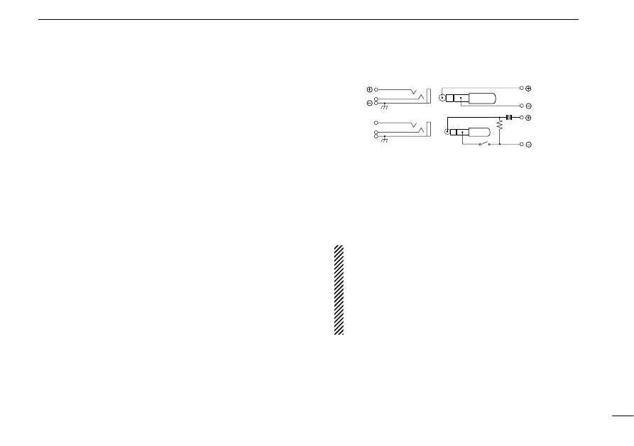
@4
EXTERNAL SPEAKER AND MICROPHONE JACKS
[SP/MIC]
Connect an optional speaker-microphone or headset, if de-
sired. The internal microphone and speaker will not func-
tion when either is connected. (See p. 43 for a list of
available options.)
D
External connection
@5
EXTERNAL DC POWER JACK [DC13.5V]
Allows operation with a 13.5 V DC power source using the
optional cables, CP-12/L or OPC-254/L.
CAUTION:
Operation with an external DC power
source simultaneously charges batteries inside the bat-
tery case or the battery pack. When using dry cell bat-
teries this may cause battery leakage and damage the
transceiver; when using a Ni-Cd battery pack this may
cause battery overcharging and shorten the life of the
battery pack.
The above connection does not apply when a
condensor microphone is connected.
Remote
Audio out
(8
Ω
)
[SP]
MIC
3.5 V
PTT
[MIC]
Audio input
PTT
33 k
Ω
(2 k
Ω
)
1
PANEL DESCRIPTION
6
LOW
T SQL
DUP
MAIN
MAIN
S
GUIDE
75
50
25
LOW
75
50
25
T SQL
DUP
S
q
q
w
e
t
r
w
u
u
i
o
!0
y
e
t
r
y
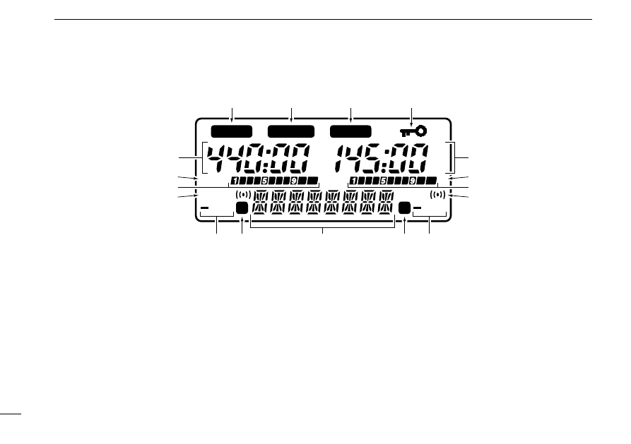
■
Function display
q
MAIN BAND INDICATORS (p. 13)
Appear above the frequency which is selected as the main
band.
• Only one of these indicators appears at a time.
w
FREQUENCY READOUTS
Show the operating frequency, set mode contents, etc.
• The frequency on the left and right can be exchanged. (p. 13)
• The smaller “75,” “50” and “25” to the right of each readout indi-
cate 7.5, 5.0 and 2.5 kHz, respectively.
• The decimal point of the frequency flashes during scan. (p. 29)
• While operating in the avionics band, a colon appears to indicate
AM mode. (U.S.A. and Asia versions only)

1
PANEL DESCRIPTION
7
e
LOW POWER INDICATORS (p. 17)
Appear when low output power is selected.
r
S/RF INDICATORS (p. 17)
➥
Show the relative signal strength while receiving.
➥
Show the output power selection while transmitting.
t
TONE INDICATORS (pgs. 19, 32)
“T” appears when the subaudible tone encoder is in use;
“T SQL
S
” appears during pocket beep operation and
“T SQL” appears when the tone squelch function is acti-
vated.
y
DUPLEX INDICATORS (p. 19)
Appear when semi-duplex operation (repeater operation)
is in use.
• “– DUP” appears when minus duplex is selected; “DUP” only, ap-
pears when plus duplex is selected.
u
SKIP INDICATORS
➥
Appear when a selected memory channel is set as a
skip channel. (p. 30)
• Skip channels are not detected (ignored) during memory
scan.
➥
Flash during full/programmed scan when the frequency
skip function is activated. (p. 31)
i
ALPHANUMERIC READOUT
➥
Shows the selected memory channel number in mem-
ory mode.
• Memory name can be selected instead of channel numbers.
(p. 24)
➥
Shows guide (or description) when the [L/G] and desired
keys are pushed, or no key operation is performed for 5
sec. in set mode, during name programming, etc. (p. 34)
o
LOCK INDICATOR (p. 15)
Indicates that the lock function is in use.
!0
QUICK GUIDE INDICATOR (p. 34)
Appears when the quick guide function is activated.

BATTERY PACKS AND ACCESSORIES
2
8
■
Battery pack charging
The supplied* BP-173 or BP-180
BATTERY PACK
includes
rechargeable Ni-Cd batteries and can be charged approx.
300 times. Charge the battery pack before first operating the
transceiver or when the battery pack becomes exhausted.
* Optional for versions which come with the BP-170
BATTERY CASE
.
If you want to be able to charge the battery pack more than
300 times, the following points should be observed:
1. Avoid overcharging. The charging period should be less
than 48 hours.
2. Use the battery until it becomes almost completely ex-
hausted under normal conditions. We recommend battery
charging just after transmitting becomes impossible.
■
Charging precautions
NEVER attempt to charge dry cell batteries. This will cause
internal liquid leakage and damage the battery case and
transceiver.
NEVER connect two or more chargers at the same time.
Charging may not occur under temperatures of 10°C (50°F)
or over temperatures of 40°C (104°F).
■
About the battery pack
D
Operating period
Depending on the attached battery pack, the operating period
of the transceiver varies. Refer to p. 43 for battery pack spec-
ifications.
D
Battery pack life
If your battery pack seems to have no capacity even after
being fully charged, completely discharge it by leaving the
power ON overnight. Then, fully charge the battery pack
again.
If the battery pack still does not retain a charge (or very little),
a new battery pack must be purchased.
D
Recycling information
(U.S.A. only)
The product that you have purchased contains a
rechargeable battery. The battery is recyclable. At
the end of its life, under various state and local
laws, it may be illegal to dispose of this battery into
the municipal waste stream. Call 1-800-8-BATTERY for bat-
tery recycling options in your area or contact your dealer.
RBRC
R
B
R
C
Ni-Cd
2
BATTERY PACKS AND ACCESSORIES
9
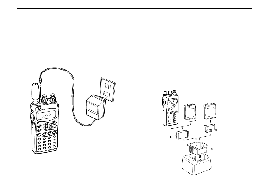
■
Charging connections
D
Regular charging
Attach the supplied* or optional battery pack; then, connect
the supplied* wall charger via an AC outlet as shown below.
* Optional for versions which include a battery case.
To [DC13.5V]
Wall charger
Any battery
pack
attached to
transceiver
Check orientation
for correct
charging
BP-171 or BP-172
without transceiver
BP-173 or
BP-180
Packed
together
as the
AD-51
(optional)
AD-51B
BC-119 + AD-75
(optional)
AD-51A
Charging periods:
1 hour (w/BP-171
or BP-180)
1.5 hours (w/BP-172 or BP-173)
Charging periods:
15 hours (w/BP-171, BP-173 or BP-180)
20 hours (w/BP-172)
D
Rapid charging with the BC-119
q
Insert the AD-51A into the charging slot of the BC-119.
• The AD-75 may be additionally necessary if the BC-119 contains
no connection terminals.
w
Insert the AD-51B into the groove in the AD-51A (front-fac-
ing side of the AD-51A) observing the proper orientation.
e
Insert the battery pack, either by itself or attached to the
transceiver, into the AD-51A.
2
BATTERY PACKS AND ACCESSORIES
10
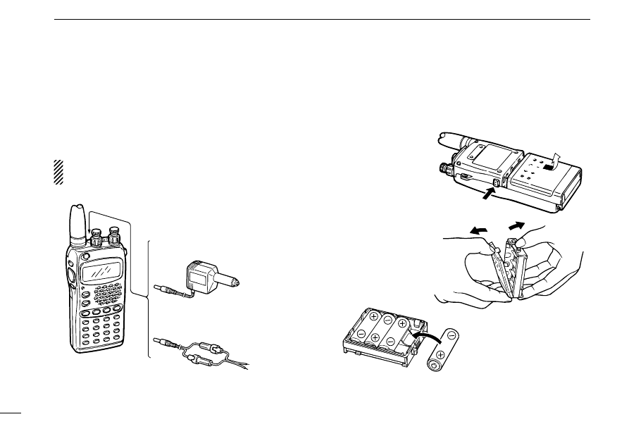
D
Operation with an optional cable
Connect an optional charger or cable to the transceiver as il-
lustrated below. Be careful of battery overcharging as the con-
nected battery is charged simultaneously.
CAUTION: Remove dry cell batteries from the BP-170
BAT
-
TERY CASE
when using the [DC13.5V] jack.
■
Battery case
When using a battery case attached to the transceiver, install
4 AA(R6) size alkaline batteries as illustrated below.
Open the case.
Remove the case
from the transceiver.
Install 4 AA(R6) size dry
cell batteries into the
battery case.
CP-12
(optional)
OPC-254
(optional)
To a 12 V cigarette
lighter socket
To a 4.5 to 16 V DC
power source
To [DC13.5V]
white
+
black
_
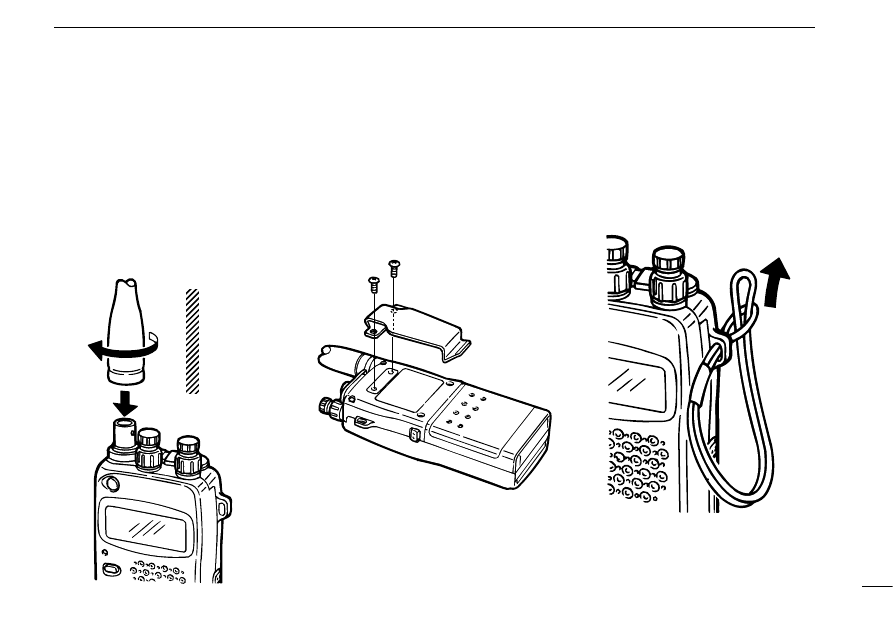
D
Antenna
Insert the supplied antenna into the an-
tenna connector and rotate the antenna
as shown in the diagram below.
Keep the jack cover attached when
jacks are not in use to avoid bad con-
tacts.
D
Belt clip
Remove screws, then attach the belt
clip using the same screws. Conve-
niently attaches to your belt.
D
Handstrap
Attach the handstrap as shown in the
diagram below. Facilitates carrying.
2
BATTERY PACKS AND ACCESSORIES
11
■
Accessory attachment
CAUTION:
Transmitting
without the
antenna may
damage the
transceiver.
■
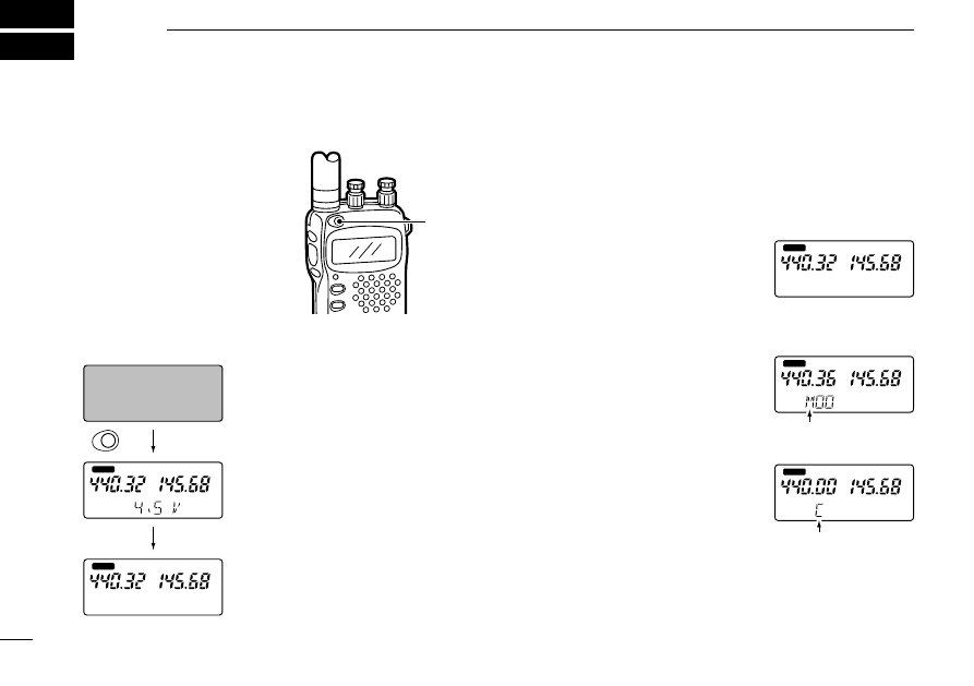
Power ON
q
Charge the battery pack or
install alkaline batteries into
the battery case. (pgs. 9,
10)
w
Push and hold [POWER]
for 2 sec. to turn power ON.
• Remaining battery voltage is
displayed for 2 sec. (p. 34)
• The display shows the approx. voltage
in 0.5 V steps.
• When the battery voltage is lower than
4.5 V, “LOW V” appears. Charge the
battery pack or place new dry cells in
the battery case in this case.
• If “OVER V” appears, UNPLUG the ex-
ternal DC plug immediately. Connected
voltage is over 16 V and could damage
the transceiver.
FREQUENCY AND CHANNEL SETTING
3
12
■
VFO and memory/call channels
This transceiver has 2 normal operating modes: VFO mode
and memory mode.
VFO mode is used for setting a desired frequency within the
band range.
➥
Push [VFO] to select VFO mode.
Memory (call) mode is used for operation of memory (call)
channels which have programmed frequencies.
➥
Push [MR] to select memory
mode.
• To program a memory, refer to p. 22.
➥
Push [CALL] to select a call chan-
nel.
What is VFO?
VFO is an abbreviation of Variable Frequency Oscillator.
Frequencies for transmitting and receiving are generated and
controlled by the VFO.
MAIN
MAIN
“M” (or a memory name)
appears.
MAIN
“C,” “VHF CALL” or
“UHF CALL” appears.
Push for
2 sec.
for 2 sec.
POWER
after 2 sec.
MAIN
MAIN
3
FREQUENCY AND CHANNEL SETTING
13
■
Main band selection
This transceiver can receive 2 band signals simultaneously.
To change frequency or to activate a function, you must des-
ignate a band, VHF or UHF, as the main band. All switches
affect the designated main band only.
• “
Q
” appears above the main band.
■
Operating band selection
The VHF display can also receive UHF, avionics band*
1
and
VHF weather channels.*
2
The UHF display can also receive
VHF band signals. Using this capability, the transceiver can
receive 2 frequencies simultaneously on either the VHF or
UHF band. In addition, a display can be turned OFF to use
the transceiver as a mono band transceiver.
q
Select the desired
band with [MAIN].
w
Push [BAND] several
times to select the de-
sired band.
• “- - - - -” appears when
the display is OFF.
• Rotating [DIAL] while
pushing [BAND] also
selects the display.
*
1
U.S.A. and Asia versions only *
2
U.S.A. version only
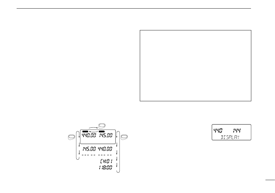
D
Exchanging the displays
]
VHF and UHF displays can be ex-
changed at power ON if desired. The
right and left displays are used for
VHF and UHF, respectively, by de-
fault.
q
Turn power ON while pushing [
(BAND)
CHNG] to enter band
arrangement condition.
w
Rotate [DIAL] to select the displays.
e
Push [VFO] to program the display selection.
r
Turn power OFF to exit band arrangement condition.
NOTE:
• VHF and UHF memory channels are called up from the
respective operating band, regardless of left/right displays.
• 5 kHz tuning steps cannot be selected in the VHF display
when both displays are set for the UHF band.
• The sub band is muted when crossband full duplex is de-
activated and the main band is transmitting.
• The sub band is muted under the following conditions
even when crossband full duplex is activated:
- Both displays show the same band.
- Sub band is the avionics band and main band is VHF transmission.
- Sub band is a weather channel and main band is UHF trans-
mission.
MAIN
MAIN
BAND
BAND
MAIN
*
2
*
1
3
FREQUENCY AND CHANNEL SETTING
14
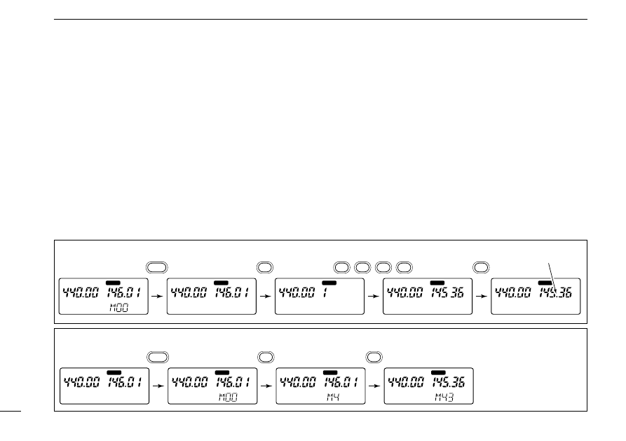
[EXAMPLE]: Setting the frequency to 145.360 MHz.
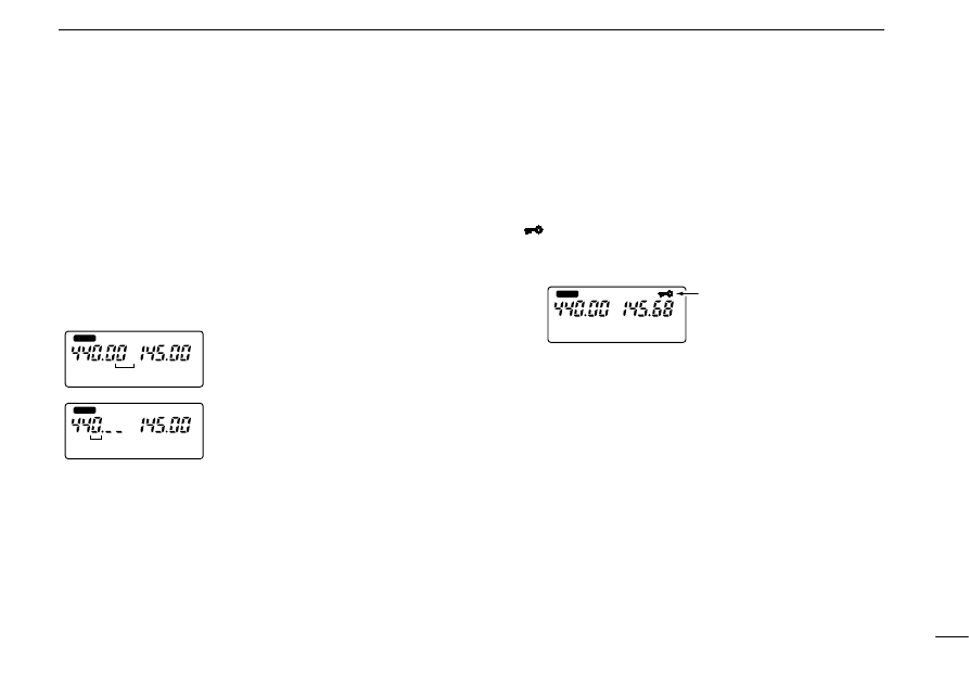
■
Frequency or channel selection via the keypad
D
Frequency
q
Assign the main band to the desired display with [MAIN].
w
Select VFO mode with [VFO].
e
Push 6 digit keys to input a frequency.
• Push [•] to input the frequency starting from the 100 kHz digit.
• When a digit is mistakenly input, push [
(VFO)
CLR] and input from
the beginning.
• “0,” “2,” “5” and “7” are acceptable for the 1 kHz digits (depending
on the 10 kHz digit).
• Any frequency in the receive frequency range can be selected,
regardless of the operating band.
D
Memory channels
q
Assign the main band to the desired display with [MAIN].
w
Select memory mode with [MR].
e
Push 2 digit keys to select the desired memory channel.
• The first ten memory channels (00–09) are preceded by a “0.”
• To select scan edge channels, 1A to 5B, use [•
(
M
)(DTMF•M)
] for
“A” and [#
(T SCAN)
] for “B.”
• Only programmed memory channels can be selected.
[EXAMPLE]: Selecting memory channel 43 (when channel 43 is already programmed).
MAIN
MAIN
MAIN
MAIN
MR
4
3
MAIN
MAIN
MAIN
MAIN
MAIN
Decimal point appears.
VFO
1
0
4
5
3
6
3
FREQUENCY AND CHANNEL SETTING
15
■
Using the tuning dial
D
Frequency
q
Assign the main band to the desired display with [MAIN].
w
Select VFO mode with [VFO].
e
Rotate the main band’s [DIAL] to change the frequency.
• The frequency changes according to the preset tuning steps.
See the next page for setting tuning steps.
• Push [
(VFO)
MHz] for 2 sec. then rotate [DIAL] to change the fre-
quency in 1 MHz steps. Push [VFO] again to return to regular
tuning steps.
D
Memory channels
q
Assign the main band to the desired display with [MAIN].
w
Select memory mode with [MR].
e
Rotate the main band’s [DIAL] to change the indicated
memory channel.
• Only programmed memory channels can be selected.
MAIN
75
50
25
MAIN
[DIAL] changes the frequency
according to the selected tuning step.
After pushing [
(VFO)
MHz] for 2 sec.,
[DIAL] changes the frequency in 1 MHz
steps.
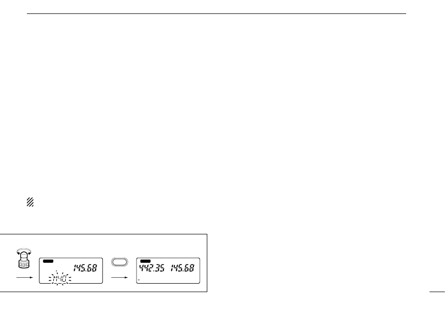
■
Lock function
The lock function prevents accidental frequency changes and
accidental function access.
➥
Push [
(CALL)
LOCK] for 2 sec. to toggle the lock function ON
and OFF.
• “
” appears while the lock function is activated.
• [POWER], [VOL], [SQL], [PTT], [L/G] and [H/L] can still be ac-
cessed while the lock function is ON.
MAIN
Appears when the
lock function is in use.
3
FREQUENCY AND CHANNEL SETTING
16
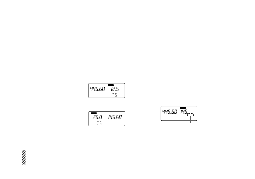
■
Setting tuning dial increments
D
Tuning step selection
[
Tuning steps can be selected for each band. This transceiver
has 8 tuning steps as follows:
• 5 kHz*
• 10 kHz
• 12.5 kHz • 15 kHz
• 20 kHz
• 25 kHz
• 30 kHz
• 50 kHz
* 5 kHz cannot be selected in the VHF display when both displays are
set for the UHF band.
q
Assign the main band to the de-
sired display with [MAIN].
w
Select VFO mode with [VFO].
e
Push [
(H/L)
SET] for 2 sec. to enter
set mode.
r
Push [
(H/L)(SET)
J
] or [
(TONE)
K
]
several times until “TS” appears.
• Previously selected tuning step ap-
pears.
t
Rotate the main band’s [DIAL] to
select the desired tuning step.
y
Push [
(VFO)
CLR] to set the se-
lected tuning step.
NOTE: Both displays have independent tuning steps ac-
cording to the operating band. (e.g. VHF band in left dis-
play: 5 kHz step; VHF band in right display: 12.5 kHz step)
D
Using 1 MHz tuning step
This transceiver has a 1 MHz tuning step for quick frequency
setting.
q
Assign the main band to the desired display with [MAIN].
w
Select VFO mode with [VFO].
e
Push [
(VFO)
MHz] for 2 sec. to select the 1 MHz tuning step.
• The digits below 100 kHz disappear.
r
Rotate the main band’s [DIAL] to change the frequency in
1 MHz steps.
t
Push [
(VFO)
CLR] to cancel the 1 MHz tuning step and to
return to the previous tuning step.
MAIN
100 kHz digit and below disappear.
MAIN
MAIN
12.5 kHz tuning step
(VHF)
25 kHz tuning step
(UHF)
BASIC OPERATION
4
17
■
Receive and transmit
CAUTION: Transmitting without an antenna may damage
the transceiver.
q
Push [POWER] for 2 sec. to turn power ON.
w
Adjust the [VOL] control to the desired level.
• While pushing [SQL], rotate the main band’s [VOL].
e
Set the squelch level.
• While pushing [SQL], rotate the main
band’s [DIAL].
• The first click of [DIAL] indicates the
current squelch level.
• “SQ1” is loose squelch and “SQ8” is
tight squelch.
• “AT” is automatic level adjustment
with a noise pulse count system.
r
Set an operating frequency.
When a signal is received:
➥
The TX/RX indicator lights green.
➥
Squelch opens and audio is emitted from the speaker.
➥
The receiving band’s S/RF indicator shows the relative signal
strength.
t
Push [H/L] to toggle output power between high and low.
• “LOW” appears when low output power is selected.
y
Push and hold [PTT] to transmit; then speak into the mic.
• Do not hold the microphone too close to your mouth or speak
too loudly. This may distort the signal.
• The TX/RX indicator lights red.
• The S/RF indicator shows the output power selection.
• The sub band can receive while transmitting on the main band,
depending on the set mode setting. (See the next page.)
u
Release [PTT] to return to receive.
➲
CONVENIENT
Monitor function: Push and hold [SQL] to listen to weak sig-
nals without disturbing the squelch settings.
Quick guide function: Push the desired key while pushing
[L/G] for a quick description of the key’s function. (p. 34)
• Push any key to cancel the quick guide.
MAIN
Automatic squelch is
selected.
4
BASIC OPERATION
18
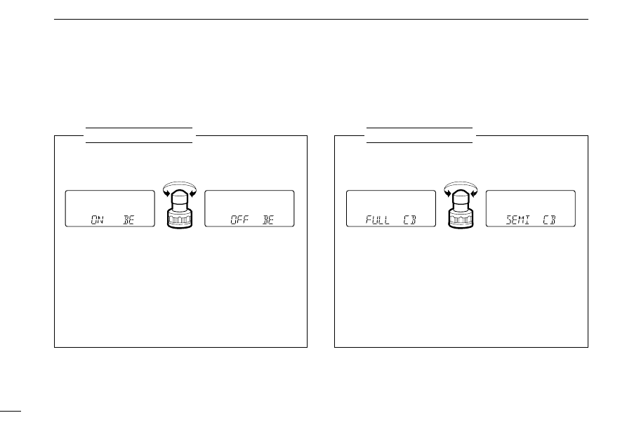
SELECTING CROSSBAND FULL DUPLEX OR
SEMI-DUPLEX
q
Turn power ON while pushing [
(H/L)
SET] to enter initial
set mode.
w
Push [
(H/L)(SET)
J
] or [
(TONE)
K
] several times until “CB”
appears as shown above.
e
Rotate [DIAL] to select semi-duplex or full duplex.
r
Turn power OFF to exit initial set mode.
D
Beep tones on/off
The confirmation beep tones, which sound each time a switch
is pushed, can be turned ON or OFF, as desired.
D
Crossband full duplex operation
The crossband full duplex function can be turned ON or OFF
in initial set mode. When the function is OFF, the sub band
audio is muted during transmission.
SETTING THE CONFIRMATION BEEP ON/OFF
q
Turn power ON while pushing [
(H/L)
SET] to enter initial
set mode.
w
Push [
(H/L)(SET)
J
] or [
(TONE)
K
] several times until “BE”
appears as shown above.
e
Rotate [DIAL] to turn the confirmation beep ON or OFF.
r
Turn power OFF to exit initial set mode.
USING
Initial set mode
USING
Initial set mode
Confirmation beep is ON.
Confirmation beep is OFF.
Crossband full duplex
is OFF. (semi duplex)
Crossband full duplex
is ON.

➲
CONVENIENT
Tone scan function: When you don’t know the subaudible
tone used for a repeater, the tone scan is convenient for de-
tecting the tone frequency.
Push [
(#)
T SCAN] for 2 sec. to activate. See p. 33 for more in-
formation.
REPEATER OPERATION
5
19
■
General
When using a repeater, the transmit frequency is shifted from
the receive frequency by the offset frequency. (p. 20) It is con-
venient to program repeater information into memory chan-
nels. (p. 22)
q
Assign the main band to the desired display with [MAIN].
w
Set the receive frequency (repeater output frequency).
e
Push [
(TONE)
DUP] for 2 sec. once to select – DUP or twice
to select DUP.
• “– DUP” or “DUP” appears to indicate the transmit frequency for
minus shift or plus shift, respectively.
• When the auto repeater function is in use (U.S.A. version only),
this selection and step
r
are not necessary. (p. 21)
r
Push [TONE] to activate the subaudible tone encoder, ac-
cording to repeater requirements.
• Refer to the next page for tone frequency settings.
t
Push and hold [PTT] to transmit.
• The displayed frequency automatically changes to the transmit
frequency (repeater input frequency).
• If “oFF” appears, check the offset frequency. (p. 20)
y
Release [PTT] to receive.
u
Push and hold [SQL] to check whether the other station’s
transmit signal can be directly received or not.
Some repeaters require DTMF tones or a 1750 Hz tone to
be accessed. In this case, perform the following instead of
step
r
at left with the required tone.
DTMF TONES (IC-W32A only)
While pushing [PTT], push the desired digit key(s) to trans-
mit DTMF tones.
• The transceiver has 4 DTMF memory channels. See p. 26 for de-
tails.
1750 Hz TONE (Europe, Italy and U.K. versions only)
While pushing [PTT], push and hold [CALL] for 1 to 2 sec.
to transmit a 1750 Hz tone burst signal.
• Pushing [PTT] 2 times quickly also transmits a 1750 Hz tone. Re-
lease [PTT] briefly, then push [PTT] again to talk in this case.
■
Subaudible tones
Some repeaters require subaudible tones to be accessed.
Subaudible tones are superimposed over your normal signal
and must be set in advance.
5
REPEATER OPERATION
20
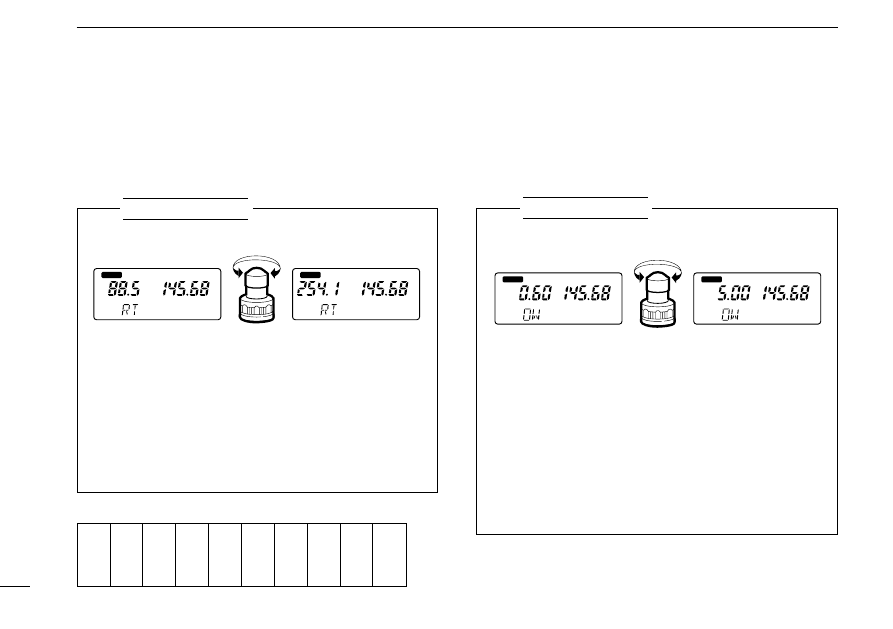
■
Offset frequency
When communicating through a repeater, the transmit fre-
quency is shifted from the receive frequency by an amount
determined by the offset frequency.
q
Push [
(H/L)
SET] for 2 sec. to enter set mode.
w
Push [
(H/L)(SET)
J
] or [
(TONE)
K
] several times until “RT”
appears as shown above.
e
Rotate [DIAL] to select the desired subaudible tone.
• Each operating band for each display and each memory chan-
nel have independent settings.
r
Push [
(
VFO
)
CLR] to set the condition and to exit set
mode.
USING
SET MODE
88.5 Hz tone
254.1 Hz tone
MAIN
T
MAIN
T
SETTING AN OFFSET FREQUENCY
q
Push [VFO] to select VFO mode.
w
Push [
(H/L)
SET] for 2 sec. to enter set mode.
e
Push [
(H/L)(SET)
J
] or [
(TONE)
K
] several times until “OW”
appears as shown above.
r
Rotate [DIAL] to select the desired offset (separately se-
lectable for each band).
• Pushing [
(VFO)
MHz] for 2 sec. selects MHz steps.
t
Push [
(
VFO
)
CLR] to set the condition and to exit set
mode.
USING
SET MODE
0.6 MHz (600 kHz) offset
5.0 MHz offset
MAIN
MAIN
67.0
69.3
71.9
74.4
77.0
79.7
82.5
85.4
88.5
91.5
94.8
97.4
100.0
103.5
107.2
110.9
114.8
118.8
123.0
127.3
131.8
136.5
141.3
146.2
151.4
156.7
159.8
162.2
165.5
167.9
171.3
173.8
177.3
179.9
183.5
186.2
189.9
192.8
196.6
199.5
203.5
206.5
210.7
218.1
225.7
229.1
233.6
241.8
250.3
254.1
• Subaudible tone frequency list
(Unit: Hz)
SETTING SUBAUDIBLE TONES
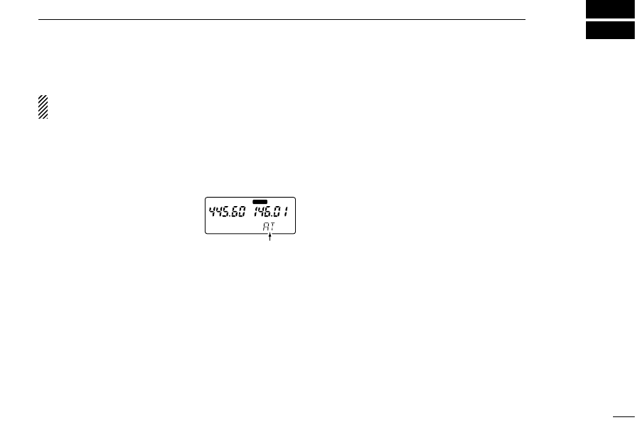
■
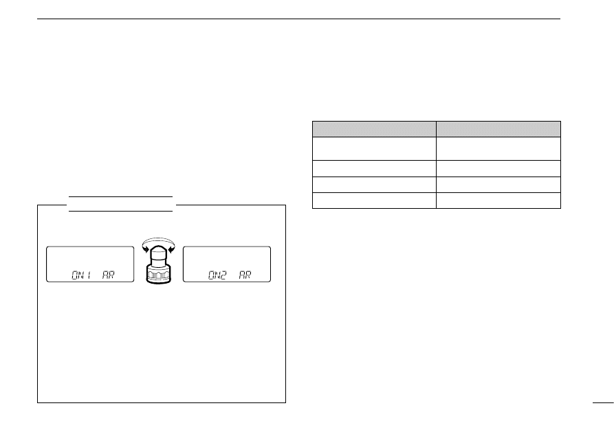
Auto repeater function
(U.S.A. version only)
The U.S.A. version automatically activates the repeater set-
tings (duplex ON/OFF, duplex direction, tone encoder
ON/OFF) when the operating frequency falls within or outside
of the general repeater output frequency range. The offset
and repeater tone frequencies are not changed by the auto
repeater function, reset these frequencies, if necessary.
5
REPEATER OPERATION
21
SETTING THE AUTO REPEATER FUNCTION
q
Turn power ON while pushing [
(H/L)
SET] to enter initial
set mode.
w
Push [
(H/L)(SET)
J
] or [
(TONE)
K
] several times until “AR”
appears as shown above.
e
Rotate [DIAL] to turn the auto repeater function ON
(“ON1” and “ON2”) or OFF.
r
Turn power OFF to exit initial set mode.
USING
Initial set mode
Activates for duplex only.
Activates for duplex and tone.
• Frequency range and offset direction
FREQUENCY RANGE
DUPLEX DIRECTION
145.200–145.495 MHz
146.610–146.995 MHz
“–DUP” appears
147.000–147.395 MHz
“DUP” appears
–
442.000–444.995 MHz
“DUP” appears
–
447.000–449.995 MHz
“–DUP” appears

MEMORY/CALL PROGRAMMING
6
22
■
General
The transceiver has 100 memory channels (plus 5 pairs of
scan edge channels) and 1 call channel on each band for
storage of often-used frequencies.
Avionics band frequencies are stored in the VHF memory
channels (U.S.A. and Asia versions only).
D
Memory/call channel contents
The following information can be programmed into memory/
call channels:
• Operating frequency
• 8-digit memory name*
1
• Duplex direction (DUP or – DUP) with an offset frequency
(pgs. 19, 20)
• Subaudible tone encoder or tone squelch ON/OFF (pgs. 19,
32)
• Subaudible tone and tone squelch frequencies (pgs. 20, 32)
• Skip information*
2
(p. 30)
*
1
Except for call channels.
*
2
Except for the scan edge memory channels.
■
Programming during selection
q
Assign the main band to the desired display with [MAIN].
w
Select VFO mode with [VFO].
e
Set the desired frequency:
➥
Set the frequency using the keypad or [DIAL].
➥
Set other data (e.g. offset frequency, duplex direction,
subaudible tone frequency, etc.), if required.
r
Push [S.MW] momentarily to indicate memory channels.
• Do not hold [S.MW] for more than 0.5 sec., otherwise the mem-
ory channel will overwrite the displayed number.
t
Rotate [DIAL] to select the desired channel.
• Call channel (CAL) and scan edge channels (1A–5B), as well as
regular memory channels, can be programmed in this way.
y
Push [
(S.MW)
MW] for 2 sec. to program.
T SQL
DUP
MAIN
MAIN
momentarily
Set frequency and other data.
S.MW
[EXAMPLE]: Memory programming of ch 40 during selection.
■
Programming after selection
q
Assign the main band to the desired display with [MAIN].
w
Select the memory channel to be programmed.
➥
Push [MR] to select memory mode.
➥
Rotate [DIAL] or push 2 digit keys to select the memory
channel (only programmed memories can be selected).
e
Set the desired frequency in VFO mode:
➥
Push [VFO] to select VFO mode.
➥
Set the desired frequency using the keypad or [DIAL].
➥
Set other data (e.g. offset frequency, duplex direction,
subaudible tone frequency, etc.), if required.
r
Push [
(S.MW)
MW] for 2 sec. to program.
• If beep tones are turned ON, 3 beeps alert you that the VFO con-
tents, including duplex information, subaudible tone frequency,
etc., are programmed.
NOTE: Call channels cannot be programmed in this way.
6
MEMORY/CALL PROGRAMMING
23
■
Memory edit
(transferring)
Memory (call) channel contents can be moved to VFO or to
another memory.
D
Memory/call
➾
VFO
q
Assign the main band to the desired display with [MAIN].
w
Select the memory (call) channel to be transferred:
➥
Push [MR] (or [CALL]) to select memory (call) mode.
➥
Rotate [DIAL] or push 2 digit keys to select the memory
channel (only programmed memories can be selected).
e
Push [
(S.MW)
MW] for 2 sec. to transfer.
• The contents are transferred and VFO mode is selected.
D
Memory/call
➾
memory/call
q
Assign the main band to the desired display with [MAIN].
w
Select the memory (call) channel to be transferred:
➥
Push [MR] (or [CALL]) to select memory (call) mode.
➥
Rotate [DIAL] or push 2 digit keys to select the memory
channel (only programmed memories can be selected).
e
Push [
(S.MW)
MW] momentarily.
• “VFO” appears in the display.
r
Rotate [DIAL] to select a memory or call channel to trans-
fer the data.
t
Push [
(S.MW)
MW] for 2 sec. to transfer.
• The contents are transferred and the original channel is selected.
MAIN
T SQL
DUP
MAIN
for 2 sec.
S.MW
The following characters can be used in names:
➥
0 to 9, A to Z (capitals), (space),
〈
,
〉
,
M
, +, –, “ ” /, “ ”
and =.
NOTE: While using the monitor function, the frequency
readout shows the transmit frequency even when memory
name indication is selected.
6
MEMORY/CALL PROGRAMMING
24
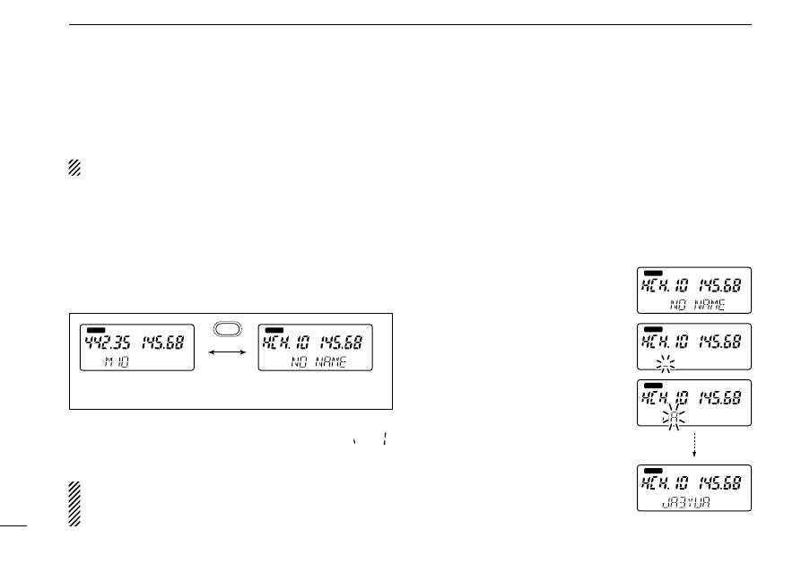
D
Programming memory names
q
Assign the main band to the desired display with [MAIN].
w
Select the memory channel to be programmed:
➥
Push [MR] to select memory mode.
➥
Rotate [DIAL] or push 2 digit keys to select the memory
channel (only programmed memories can be selected).
e
Push [M•N] to select memory name indication.
r
Push [
(M•N)
MN•W] for 2 sec. to enter memory name writ-
ing mode.
• The first character of the name
flashes.
t
Enter the desired name via the
keypad or [DIAL].
• Push the appropriate keys to input
the desired characters using the
same convention as for telephones.
• To erase a character, overwrite with
a “space” using the [
(0)
Symbol] key.
• To move the cursor forwards or back-
wards, use the [
(M•N)
≈]
or [
(#)
Ω
] key.
y
Push [
(VFO)
CLR] to input the set
name.
• Flashing stops.
• Eight characters is the maximum for
a name.
■
Memory names
Memory channels can be programmed with names of up to 8
characters in length.
Names cannot be programmed into the call channel.
D
Frequency
↔
name
To toggle between frequency indication and memory name
indication:
➥
Push [M•N] to toggle between frequency and name indi-
cations.
• “NO NAME” appears when a memory channel has not been
programmed with a name.
Frequency indication
Name indication
“H” indicates ‘High’ band (UHF)
MAIN
MAIN
M•N
MAIN
MAIN
MAIN
MAIN
6
MEMORY/CALL PROGRAMMING
25
WEATHER CHANNELS (U.S.A. version only)
There are 10 weather channels for
monitoring weather channels from
the NOAA (National Oceano-
graphic and Atmospheric Adminis-
tration) broadcasts.
Weather channels cannot be programmed into a mem-
ory channel.
q
Push [MAIN] to select VHF display as the main band.
w
Push [BAND] several times to select a weather channel.
e
Rotate [DIAL] to select the desired channel.
MAIN
■
Memory clear
Unwanted memory channels can be cleared (erased). Before
clearing a memory channel make sure it is no longer needed
as cleared memories cannot be recalled.
q
Assign the main band to the desired display with [MAIN].
w
Push [S.MW] momentarily.
• “VFO” or memory channel number flashes.
e
Select the memory channel to be cleared.
• Scan edges 1A and 1B and call channel cannot be cleared.
r
Push [S.MW] briefly, then a second time for 2 sec.
• 3 beeps sound, then the frequency is cleared.
• Memory channel number flashes continuously.
t
Push [
(VFO)
CLR] to stop the flashing.
[EXAMPLE]: Clearing memory channel 5.
momentarily, then a
second time for 2 sec.
S.MW
S.MW
momentarily
VFO
MAIN
MAIN
MAIN
MAIN
MAIN
DTMF MEMORY
7
26
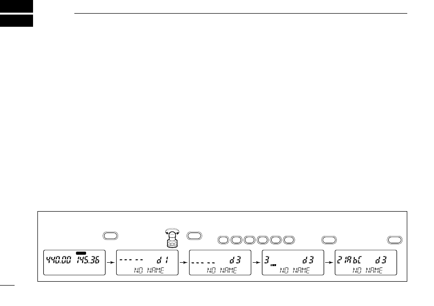
■
Programming a DTMF code
The transceiver has 4 DTMF memory channels (d1 to d4) for
storage of often-used DTMF codes of up to 16 digits. The
memory channels are for common use on both bands.
q
Push [
(•)
DTMF•M] for 2 sec. to enter DTMF memory mode.
w
Rotate either band’s [DIAL] to select the desired channel.
e
Push [
(•)
DTMF•M] for 2 sec. to enter DTMF programming
mode.
• “--- --” appears.
• Programmed DTMF code is cleared in this way.
r
Push digit keys to enter the desired DTMF code.
• The S/RF indicator shows the digit group. The indication in-
creases from no indication, 3 digits and 7 digits.
• If a pause time (2 sec.) is required in the DTMF code, push
[CALL] to input a pause code.
t
Push [
(VFO)
CLR] to store them.
y
Program DTMF memory name in a similar manner to
memory channel names, if desired.
➥
Push [
(M•N)
MN•W] for 2 sec. to enter name writing mode.
➥
Enter the desired name via the keypad or [DIAL].
• To erase a character, overwrite with a “space” using the
[
(0)
Symbol] key.
• To move the cursor forwards or backwards, use the [
(M•N)
≈]
or
[
(#)
Ω
] key.
➥
Push [
(VFO)
CLR] to input the set name.
u
Push [
(VFO)
CLR] to exit DTMF memory mode.
[EXAMPLE]: Programming “21ABC3” into DTMF memory “d3.”
•
DTMF•M
2
1
1
1
1
1
1
A
B
C
3
MAIN
for 2 sec.
for 2 sec.
VFO
VFO
•
DTMF•M
7
DTMF MEMORY
27
■
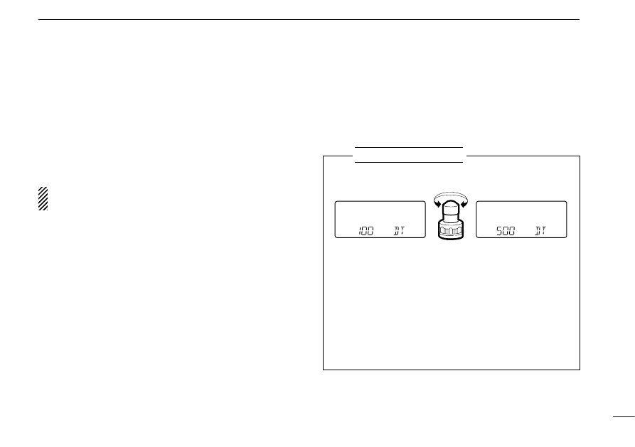
DTMF transmission speed
When slow DTMF transmission speeds are required (as for
some repeaters), the transceiver’s rate of DTMF transmission
can be adjusted.
■
Transmitting a DTMF code
D
Using a DTMF memory channel
q
Push [
(•)
DTMF•M] for 2 sec. to enter DTMF memory mode.
w
Rotate either band’s [DIAL] to select the desired channel.
e
Push [
(VFO)
CLR] again to exit DTMF memory mode.
r
While pushing [PTT], push [
(MAIN)(SCAN)
DTMF] to transmit
the selected DTMF code.
NOTE: Push [
(MAIN)(SCAN)
DTMF] while in DTMF memory
mode to monitor a DTMF channel without transmitting it.
SETTING THE DTMF TRANSMISSION SPEED
q
Turn power ON while pushing [
(H/L)
SET] to enter initial
set mode.
w
Push [
(H/L)(SET)
J
] or [
(TONE)
K
] several times until “DT”
appears as shown above.
e
Rotate [DIAL] to select the DTMF transmission speed.
r
Turn power OFF to exit initial set mode.
USING
Initial set mode
Fastest (100 msec.
intervals)
Slowest (500 msec.
intervals)
SCAN OPERATION
8
28
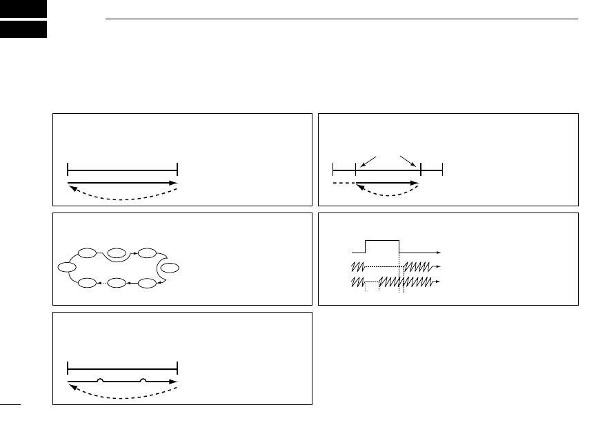
FULL SCAN (p. 29)
Repeatedly scans all fre-
quencies over the entire
band.
PROGRAMMED SCAN
(p. 29)
Repeatedly scans between
two user-programmed fre-
quencies. Used for check-
ing for frequencies within a
specified range such as
repeater output frequen-
cies, etc.
SCAN RESUME CONDITION
(p. 30)
4 resume conditions are
available: pause scan and
3 timer scans. When
receiving a signal, pause
scan pauses until the sig-
nal disappears; timer scans
pause for 5, 10 or 15 sec.
Band
edge
Band
edge
Scan
Jump
Band edge or
scan edge
Band edge or
scan edge
FREQUENCY SKIP
FUNCTION (p. 31)
Skips unwanted frequen-
cies that inconveniently
stop scanning. This func-
tion can be turned ON and
OFF in scan set mode.
Band
edge
Band
edge
Scan
Jump
Scan edges
MEMORY SKIP SCAN (p. 29)
Repeatedly scans memory
channels except skip
channels.
Not yet
programmed
SKIP
Mch 0
Mch 1
Mch 2
Mch 3
Mch 4
Mch 5
Mch 6
Mch 99
Pause
scan
Receiving
a signal
Timer
scan
Pausing
2 sec.
Jump
Skip
Skip
Scan
Each band has 3 scan types with skip functions and 4 resume
conditions providing scanning versatility. Scans on both bands
can be operated separately or simultaneously.
■
Scan types

8
SCAN OPERATION
29
■
Full/programmed scan
q
Assign the main band to the desired display with [MAIN].
w
Select VFO mode with [VFO].
e
Make sure the squelch is set to the threshold point.
• Select automatic squelch (AT) or a level (SQ1–SQ8) where the
noise is muted. (p. 17)
r
Push [
(MAIN)
SCAN] for 2 sec. to start the programmed
scan.
• Decimal point flashes while scanning.
• “P1” – “P5” flash to indicate which pair of scan edges is being
scanned.
• To change the scanning direction, rotate [DIAL].
• If the pocket beep function is activated, the transceiver automat-
ically selects the tone squelch function when a scan starts.
t
Push [1] – [5] to select the desired scan range or push [0]
to select full scan.
y
To stop the scan, push [
(VFO)
CLR].
For programmed scan, scan edges must be programmed
in advance. Program scan edges in the same manner as
regular memory channels. (p. 22)
If the same frequencies are programmed into a pair of
scan edges, a programmed scan edge appears, such as
“P1,” but programmed scan does not proceed.
■
Memory scan
q
Assign the main band to the desired display with [MAIN].
w
Select memory mode with [MR].
e
Make sure the squelch is set to the threshold point.
• Select automatic squelch (AT) or a level (SQ1–SQ8) where the
noise is muted. (p. 17)
r
Push [
(MAIN)
SCAN] for 2 sec. to start the memory scan.
• To change the scanning direction, rotate [DIAL].
• If the pocket beep function is activated, the transceiver automat-
ically selects the tone squelch function when a scan starts.
t
To stop the scan, push [
(VFO)
CLR].
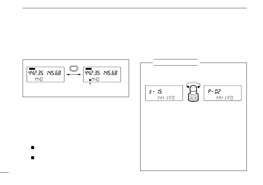
■
Scan resume condition
The resume condition can be selected as a pause or timer
scan for each band (VHF VFO and memory channels, UHF
VFO and memory channels, avionics* band).
■
Skip channel setting
Memory channels can be set to be skipped for memory skip
scan. This is useful to speedup the memory skip scan inter-
val.
q
Select the memory channel to be programmed as a skip
channel:
➥
Push [MAIN] to select the desired band.
➥
Push [MR] to select memory mode.
➥
Rotate [DIAL] or push 2 digit keys to select the memory
channel.
w
Push [
(MR)
SKIP] for 2 sec. to set the memory channel as a
skip channel.
• “
” appears.
e
Repeat step
w
to cancel a skip channel.
• “
” disappears.
S
S
8
SCAN OPERATION
30
Indicates the channel is set
as a skip channel.
MAIN
MAIN
S
Push for
2 sec.
MR
SKIP
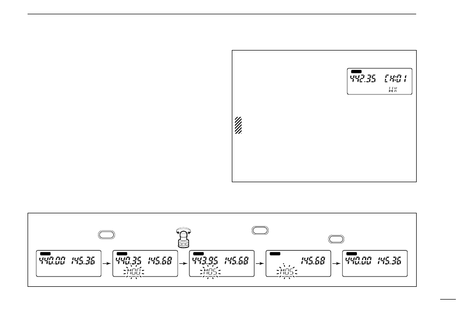
q
Turn power ON while pushing [
(MAIN)
SCAN] to enter
scan set mode.
w
Push [
(H/L)
J
] or [
(TONE)
K
] several times to select the de-
sired band to be set.
• Avionics*/144/430(440) VFO, VHF/UHF memories are available.
e
Rotate [DIAL] to select the desired resume condition.
• “t-15”: scan pauses for 15 sec. on a received signal.
• “t-10”: scan pauses for 10 sec. on a received signal.
• “t-05”: scan pauses for 5 sec. on a received signal.
• “P-02”: scan pauses on a received signal until it disappears.
r
Turn power OFF to exit scan set mode.
USING
Scan set mode
15 sec. timer for resume
condition
Pauses until the signal
disappears
* U.S.A. and Asia versions only.
SETTING THE SCAN RESUME CONDITION
(Following displays show the 144 MHz band full/programmed scan)
8
SCAN OPERATION
31
■
Frequency skip function
D
Programming a skip frequency
Unwanted frequencies can be skipped and programmed as
skip channels when full or programmed scan is pausing.
q
Turn ON the frequency skip function as described at right.
w
Start full scan or programmed scan. (p. 29)
e
While receiving an unwanted signal and scan pauses,
push [
(S.MW)
MW] for 2 sec. to program the received fre-
quency as a skip frequency.
• Do not release [
(S.MW)
MW] before 2 sec., otherwise, scan stops
and select memory mode is selected.
• The transceiver emits 3 beeps and the scan resumes.
• Non-programmed memory channels are used for skip frequency
programming from channel 99 to 10 in reverse sequence.
• To scan the skip frequency after programming, cancel the skip
information or clear the memory channel. (pgs. 25, 30)
NOTE: When the frequency skip function is turned OFF,
the paused frequency is overwritten on the preselected
memory channel.
D
Frequency skip function ON/OFF
The frequency skip function can be turned OFF in set mode.
In this case, the frequencies will not be skipped even if skip
information is programmed and “
” will not blink during full
scan or programmed scan.
S
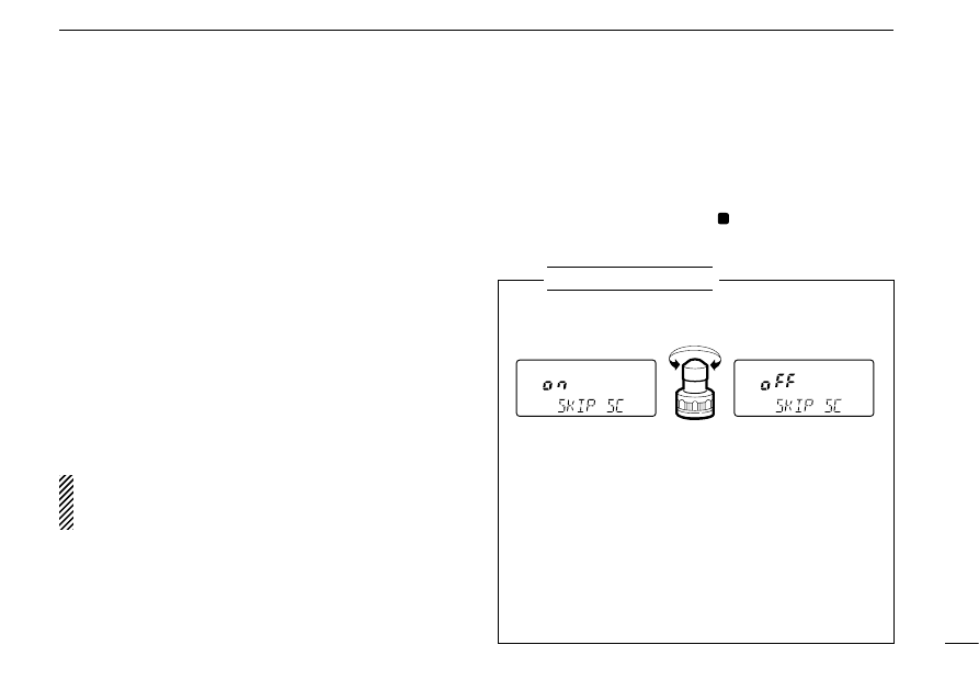
SETTING THE FREQUENCY SKIP FUNCTION ON/OFF
q
Turn power ON while pushing [
(MAIN)
SCAN] to enter
scan set mode.
w
Push [
(H/L)
J
] or [
(TONE)
K
] several times until “SKIP SC”
appears as shown above.
e
Rotate [DIAL] to turn the frequency skip function ON or
OFF.
r
Turn power OFF to exit scan set mode.
USING
Scan set mode
The frequency skip
function is ON.
The frequency skip
function is OFF.
SUBAUDIBLE TONE OPERATION
9
32
■
Tone squelch operation
D
Operation
The tone squelch opens only when receiving a signal con-
taining a matching subaudible tone. You can silently wait for
calls from group members using the same tone.
q
Assign the main band to the desired display with [MAIN].
w
Set the operating frequency.
e
Set the desired CTCSS tone in set mode.
• See right for programming.
r
Push [TONE] several times until “T SQL” appears.
t
When the received signal includes a matching tone,
squelch opens and the signal can be heard.
• When the received signal’s tone does not match, tone squelch
does not open, however, the S-indicator shows signal strength.
• To open the squelch manually, push and hold [SQL].
y
Operate the transceiver in the normal way.
u
To cancel the tone squelch, push [TONE].
NOTE: The transceiver has 50 tone frequencies and con-
sequently their spacing is narrow compared with units hav-
ing 38 tones. Therefore, some tone frequencies may
receive interference from adjacent tone frequencies.
➲
CONVENIENT
Store subaudible tone frequencies and tone squelch ON/OFF
settings in memories (call) for easy recall.
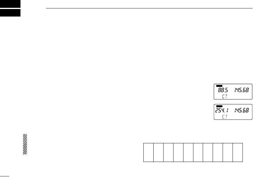
D
Setting subaudible tones for
[
tone squelch operation (CTCSS tones)
Separate tone frequencies can be set for tone squelch oper-
ation than for repeater operation (the same range of tones is
available—see below). Like repeater tones, these are set in
set mode.
q
Select VFO or a memory channel.
w
Push [
(H/L)
SET] for 2 sec. to enter
set mode.
e
Push [
(H/L)(SET)
J
] or [
(TONE)
K
]
several times until “CT” appears
as shown at right.
r
Rotate [DIAL] to select the de-
sired subaudible tone.
t
Push [
(VFO)
CLR] to exit set mode.
67.0
69.3
71.9
74.4
77.0
79.7
82.5
85.4
88.5
91.5
94.8
97.4
100.0
103.5
107.2
110.9
114.8
118.8
123.0
127.3
131.8
136.5
141.3
146.2
151.4
156.7
159.8
162.2
165.5
167.9
171.3
173.8
177.3
179.9
183.5
186.2
189.9
192.8
196.6
199.5
203.5
206.5
210.7
218.1
225.7
229.1
233.6
241.8
250.3
254.1
• Subaudible tone frequency list
(Unit: Hz)
MAIN
T
MAIN
T
SQL
SQL
9
SUBAUDIBLE TONE OPERATION
33
■
Tone scan
The transceiver can detect the subaudible tone frequency in a
received signal. By monitoring a signal that is being transmit-
ted on a repeater input frequency, you can determine the tone
frequency required to access the repeater.
q
Assign the main band to the desired display with [MAIN].
w
Set the desired frequency or memory channel to be
checked for a tone frequency.
e
Push [
(#)
T SCAN] for 2 sec. to start the tone scan.
• To change the scanning direction, rotate [DIAL].
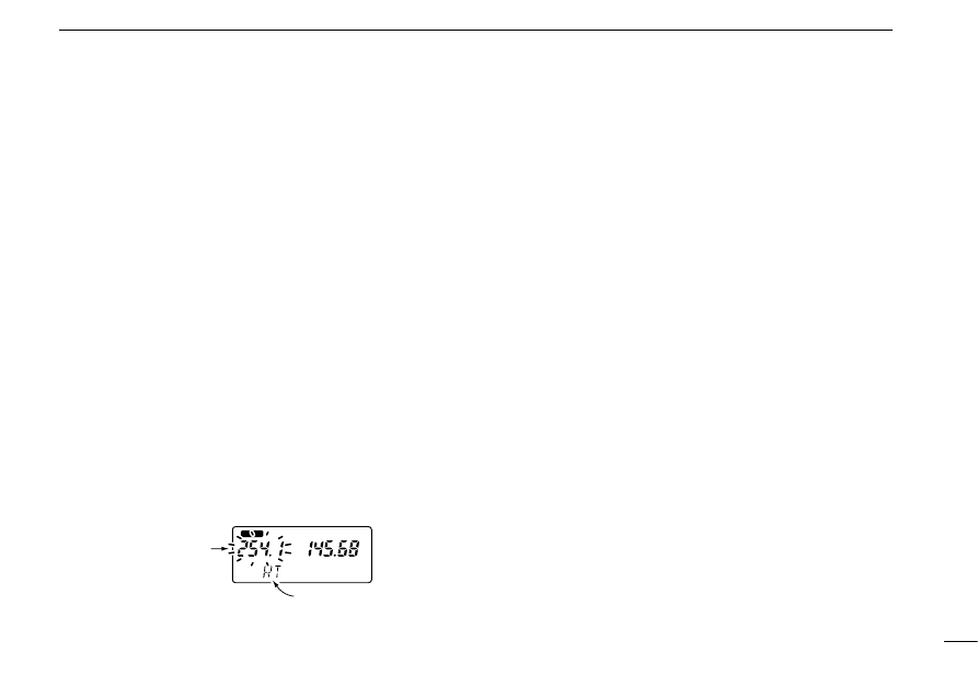
r
When the tone frequency is decoded, the set mode con-
tents are programmed with the tone frequency.
• The tone scan pauses when a tone frequency is detected.
• The decoded tone frequency is used for the tone encoder or tone
encoder/decoder, depending on the the tone squelch ON/OFF
setting.
• “CT” or “RT” appears during tone scan when the tone squelch is
in use or not.
t
Push [VFO] to stop the scan.
■
Pocket beep operation
This function uses subaudible tones for calling and can be
used as a “common pager” to inform you that someone has
called while you were away from the transceiver.
D
Waiting for a call from a specific station
q
Assign the main band to the desired display with [MAIN].
w
Set the operating frequency.
e
Set the desired CTCSS tone in set mode.
• See the opposite page for a list of available tone frequencies and
programming information.
r
Push [TONE] several times until “ T SQL
S
” appears in
the function display.
t
When a signal with the correct tone is received, the trans-
ceiver emits beep tones for 30 sec. and flashes
“ T SQL
S
.”
y
Push [PTT] to answer or push [
(VFO)
CLR] to stop the beeps
and flashing.
• Tone squelch is automatically selected.
D
Calling a waiting station using pocket beep
A subaudible tone matched with the station’s tone frequency
is necessary. Use the tone squelch on the opposite page or a
subaudible tone encoder.
MAIN
T
“RT” or “CT” appears
during tone scan
Subaudible tone
frequencies flash as
they are scanned.
OTHER FUNCTIONS
10
34
■
Guide function
The transceiver has a guide function that enables quick de-
scriptions of key functions without the need to search a menu
list.
D
Calling up a description
➥
Push the desired key while pushing the [L/G] key.
• “
” and a quick description of the key’s function appear.
[EXAMPLE]
While in set mode, memory name programming, etc., the
quick description automatically appears 5 sec. after oper-
ation. Push any key to clear the description.
GUIDE
MAIN
GUIDE
MAIN
L/G
+
MAIN
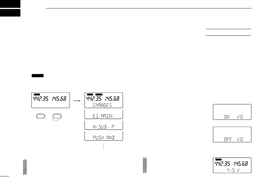
■
Battery voltage
indication
The transceiver has a battery voltage indicator to check dry
cell battery consumption in the BP-170
BATTERY CASE
. When
the indication is set to ON, the battery voltage is indicated for
2 sec. at power ON (LOW V, 4.5–16 V in 0.5 V steps).
If the battery voltage is lower than 4.5 V, “LOW V” appears.
Place new dry cells in the battery case. If the voltage sur-
passes 16 V, “OVER V” appears and flashes regardless of
this setting.
q
Turn power ON while pushing
[
(H/L)
SET] to enter initial set mode.
w
Push [
(H/L)(SET)
J
] or [
(TONE)
K
]
several times until “VO” appears
as shown at right.
e
Rotate [DIAL] to turn the voltage
indication ON or OFF.
r
Turn power OFF to exit initial set
mode.
After turning the voltage indica-
tion ON, the battery voltage is
displayed for 2 sec. at power ON.
USING
Initial set mode
MAIN
Battery indication OFF
Battery indication ON
10
OTHER FUNCTIONS
35
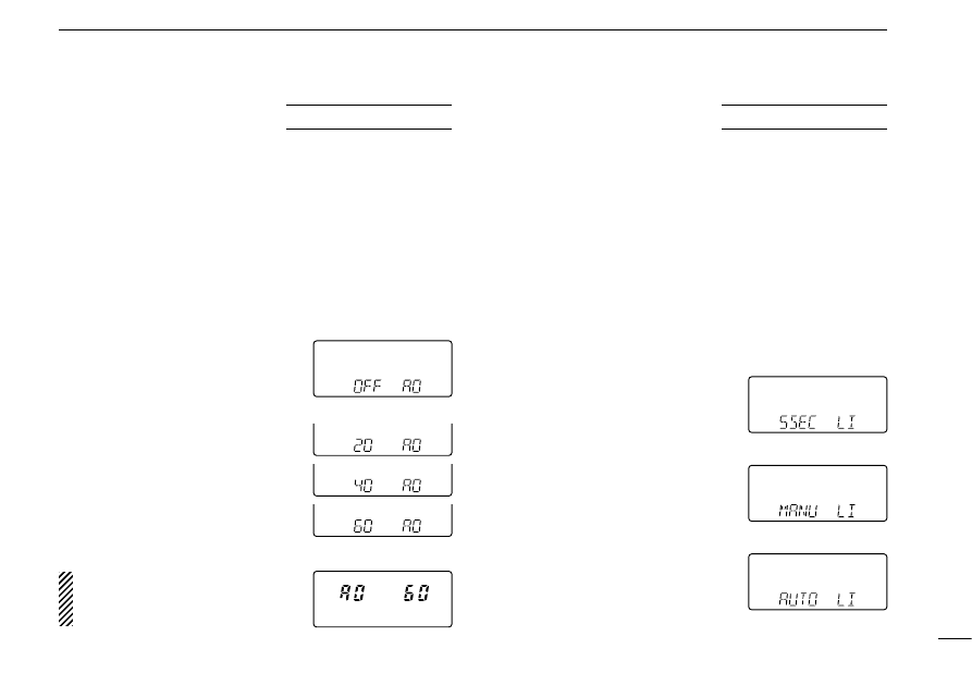
■
Auto power-off
function
The transceiver can be set to automatically turn OFF after a
specified period in which no switch is pushed.
60 min., 40 min., 20 min. and OFF can be specified. The
specified period is retained even when the transceiver is
turned OFF by the auto power-off function. To cancel the
function, select “OFF” in step
e
below.
q
Turn power ON while pushing
[
(H/L)
SET] to enter initial set mode.
w
Push [
(H/L)(SET)
J
] or [
(TONE)
K
]
several times until “AO” appears
as shown at right.
e
Rotate [DIAL] to select the de-
sired time or to turn the function
OFF.
r
Turn power OFF to exit initial set
mode.
After setting the auto power-off
time, the specified period is dis-
played for 2 sec. at power ON.
USING
Initial set mode
■
Function display
backlighting
For easy operation at nighttime, the transceiver has an LCD
(Liquid Crystal Display) and keypad lighting function.
5 sec. timer, manual and automatic can be specified. When
set to 5 sec., display backlighting can be turned ON with 5
sec. timer; when set to MANU (manual), the [L/G] key toggles
display backlighting ON and OFF; when set to AUTO, display
backlighting automatically turns ON with 5 sec. timer when
any operation is performed except [PTT].
q
Turn power ON while pushing
[
(H/L)
SET] to enter initial set mode.
w
Push [
(H/L)(SET)
J
] or [
(TONE)
K
]
several times until “LI” appears as
shown at right.
e
Rotate [DIAL] to select the de-
sired backlighting function.
r
Turn power OFF to exit initial set
mode.
USING
Initial set mode
Auto power-off is OFF.
5 sec. timer
Automatic ON with timer
Manual ON/OFF
10
OTHER FUNCTIONS
36
■
LCD contrast
The LCD (Liquid Crystal Display) contrast can be selected
from 1 of 3 levels. Select a contrast which gives the best read-
ability for the ambient light conditions. “1” is the lowest con-
trast available and “3” is the highest contrast available.
q
Turn power ON while pushing
[
(H/L)
SET] to enter initial set mode.
w
Push [
(H/L)(SET)
J
] or [
(TONE)
K
]
several times until “LC” appears
as shown at right.
e
Rotate [DIAL] to select the de-
sired contrast.
r
Turn power OFF to exit initial set
mode.
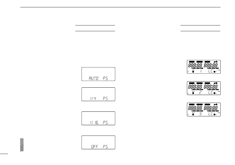
■
Power saver
The power saver function reduces the current drain to con-
serve battery power. The power saver duty cycle can be set to
automatic, 1 : 4, 1 : 16 or OFF. Setting it to 1 : 16 conserves the
most power. For packet operation, the power saver should be
turned OFF to receive reliable packet data. The power saver
is deactivated when more than 12 V DC is connected to the
[DC13.5V] jack.
q
Turn power ON while pushing
[
(H/L)
SET] to enter initial set mode.
w
Push [
(H/L)(SET)
J
] or [
(TONE)
K
]
several times until “PS” appears
as shown at right.
e
Rotate [DIAL] to select the de-
sired duty cycle or to turn the
function OFF.
• “AUTO” selects “1:4” duty ratio when
receiving no signal for 5 sec., then
“1:8” 60 sec. after that.
r
Turn power OFF to exit initial set
mode.
NOTE: When the duty cycle is set
to 1 : 16, signals may be clipped
up to a 2 sec. maximum.
USING
Initial set mode
Automatic duty cycle
Standby: 125 msec.
Circuit off: 500 msec.
Standby: 125 msec.
Circuit off: 2 sec.
Power saver is OFF.
USING
Initial set mode
Low contrast
High contrast
LOW
T SQL
DUP
MAIN
MAIN
S
GUIDE
75
50
25
LOW
75
50
25
T SQL
DUP
S
LOW
T SQL
DUP
MAIN
MAIN
S
GUIDE
75
50
25
LOW
75
50
25
T SQL
DUP
S
LOW
T SQL
DUP
MAIN
MAIN
S
GUIDE
75
50
25
LOW
75
50
25
T SQL
DUP
S
10
OTHER FUNCTIONS
37
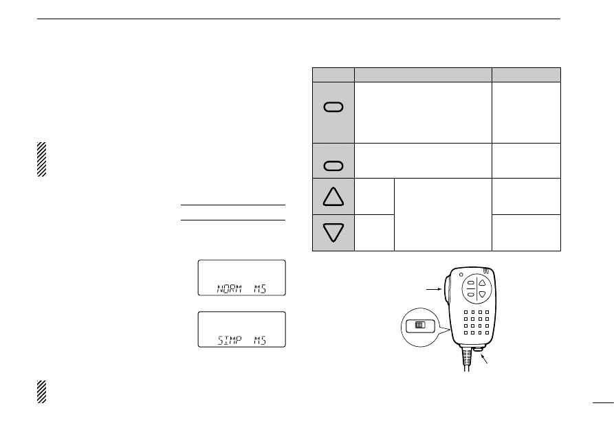
■
Optional HM-75A functions
The optional HM-75A allows you to remotely select memory
channels, operating frequency, etc. The switches on the
HM-75A function depends on the initial set mode setting.
CAUTION: When connecting the HM-75A to the trans-
ceiver, make sure that power to the transceiver is turned
OFF, otherwise the CPU may malfunction.
D
Setting the HM-75A
functions
This item turns the microphone simple mode ON or OFF.
q
Turn power ON while pushing
[
(H/L)
SET] to enter initial set mode.
w
Push [
(H/L)(SET)
J
] or [
(TONE)
K
]
several times until “MS” appears
as shown at right.
e
Rotate [DIAL] to select the de-
sired HM-75A function.
r
Turn power OFF to exit initial set
mode.
NOTE: VFO mode cannot be selected via the microphone
when SIMPLE mode is selected.
A
OFF
ON
LOCK
B
Lock switch:
Locks all switches
except [PTT]
Earphone jack
PTT switch
USING
Initial set mode
Simple mode
Normal mode
SWITCH
NORMAL
SIMPLE
MAIN (BAND)
Push to toggle the main band
assignment.
Push and hold to select the
operating band.
MONITOR
Push and hold
to open the
squelch.
VFO/MEMORY
Toggles VFO and memory mode.
CALL
Selects the call
channel.
UP
M1
Selects memory
channel 1.
DOWN
M2
Selects memory
channel 2.
Change the frequency
or memory channel
when pushed.
Starts previously
selected scan when
pushed for 2 sec.
A
B
10
OTHER FUNCTIONS
38
■
Partial reset
If you want to initialize the operating conditions (VFO fre-
quency, VFO settings, set mode contents) without clearing
the memory contents, a partial resetting function is available
for the transceiver.
➥
While pushing [
(VFO)
CLR], turn power ON to partially reset
the transceiver.
■
All reset
Reset the CPU before operating the transceiver for the first
time, or when the internal CPU malfunctions.
➥
While pushing [SQL], [VFO] and [MR], turn power ON to
reset the CPU.
CAUTION: Resetting the CPU returns all programmed
contents to their default settings.
AT
POWER ON
AT
POWER ON
■
Handheld-to-handheld
cloning
The information in the transceiver, such as memory channels,
memory names, etc. can be transferred from one IC-W32A/E
to another. An optional OPC-474
CLONING CABLE
is required.
In addition, optional CS-W32
CLONING SOFTWARE
is available
to clone and edit contents using a PC.
q
Connect the OPC-474 between
both transceiver’s [SP] jacks.
w
Turn the ‘slave’ transceiver power
ON.
e
Turn the ‘master’ transceiver
power ON while pushing [MR]
and [M•N].
• “PUSH PTT” appears.
r
Push [PTT] on the ‘master’ trans-
ceiver to transfer the data.
• “CL OUT” appears and digits (0–9,
A–F) indicate the data flow.
Cloning standby
Previous operating
condition appears.
While cloning
MAIN

TROUBLESHOOTING
11
39
If your transceiver seems to be malfunctioning, please check
the following points before sending it to a service center.
PROBLEM
POSSIBLE CAUSE
SOLUTION
REF.
• No power comes on.
• The battery is exhausted.
(A slight current flows in the circuits even when
the power is OFF).
• Poor plug connection to the external DC power
cable.
• Charge the battery pack or place new dry cell
batteries in the battery case.
(Remove the battery pack if you will not be using
the transceiver for a long time.)
• Check the connector or remove and replace the
cable.
pgs.
9, 10
—
• No sound comes from
the speaker.
• Squelch level is too deep. (e.g. SQ8)
• Volume level is too low.
• Set squelch to automatic (AT).
• Set the desired band’s [VOL] to a suitable level.
p. 17
p. 17
• Transmitting is
impossible.
• The battery is exhausted.
• Avionics band frequency (U.S.A./Asia only) or
weather channel (U.S.A. only) is selected.
• Charge the battery pack or place new dry cell
batteries in the battery case.
• Set an amateur frequency.
pgs.
9, 10
p. 13
• Frequency cannot be set.
• Memory mode or call channel is selected.
• Weather channel (U.S.A. only) is selected.
• Lock function is activated.
• Push [VFO] to select VFO mode.
• Push [BAND] to select an amateur band or
avionics band.
• Push [
(CALL)
LOCK] for 2 sec. to cancel the
function.
p. 12
p. 13
p. 15
• Scan does not start.
• The squelch is open.
• Call or weather channel (U.S.A. only) is
selected.
• Set squelch to automatic (AT) or the squelch
closed point (SQ1 or more).
• Push [BAND] to select an amateur band, memory
channel or avionics band.
p. 17
p. 13
• No contact possible with
another station.
• The transceiver is set to semi-duplex.
• The output power is set to low.
• Set to simplex.
• Push [H/L] to select high power.
p. 19
p. 17
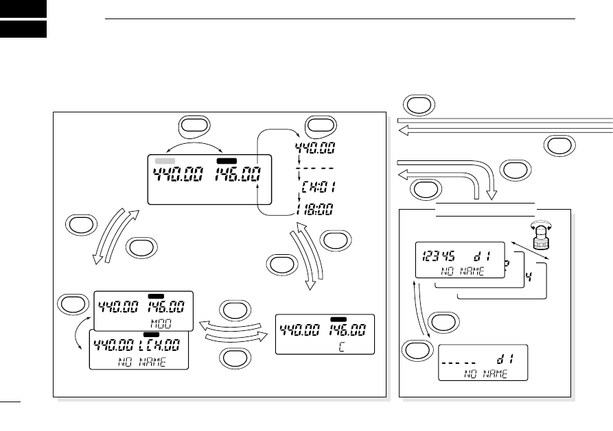
MAIN
MAIN
MAIN
MAIN
MAIN
DTMF MEMORY PROGRAMMING
DTMF MEMORY CHANNEL
MEMORY MODE
(FREQUENCY INDICATION)
(CHANNEL NAME INDICATION)
CALL CHANNEL MODE
VFO MODE
DTMF MEMORY MODE
H/L
SET
J
(push for 2 sec.)
MAIN
BAND
DTMF
•
M
•
(push for 2 sec.)
DTMF
•
M
•
MR
MR
M•N
CALL
CALL
VFO
(push for 2 sec.)
VFO
VFO
VFO
VFO
MODE ARRANGEMENT
12
40
Although the following chart refers mainly to the VHF (right) band, the same
arrangement applies to the UHF (left) band (except commonly used mode, DTMF
memory, SCAN SET and INITIAL SET).
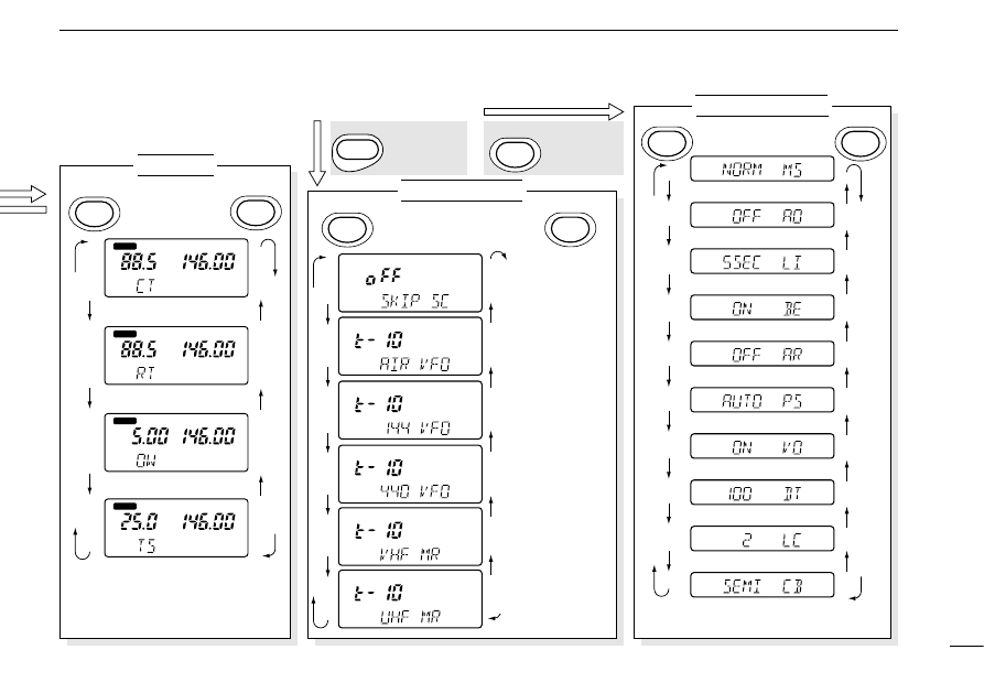
MAIN
Tuning step* (p. 16)
T
MAIN
Repeater tones (p. 20)
T SQL
MAIN
CTCSS tones (p. 32)
Backlight condition (p. 35)
Beep tones (p. 18)
Auto repeater* (p. 21)
Power saver (p. 36)
Battery voltage (p. 34)
DTMF speed (p. 27)
LCD contrast (p. 36)
Crossband full duplex (p. 18)
* U.S.A. version only
* These displays don’t appear when
entering SET mode from memory
mode or call channel mode.
MAIN
Offset frequency* (p. 20)
SET MODE
SCAN SET MODE
INITIAL SET MODE
Frequency
skip function
(p. 31)
Scan resume
for avionics
band (p. 30)
(U.S.A., Asia only)
Scan resume
for 144 MHz
band program
scan (p. 30)
Scan resume
for 440 MHz
band program
scan (p. 30)
Scan resume
for VHF
memo scan (p. 30)
Scan resume
for UHF
memo scan (p. 30)
Mic simple mode (p. 37)
Auto power OFF (p. 35)
H/L
SET
J
TONE
DUP
K
H/L
SET
J
H/L
SET
J
TONE
DUP
K
TONE
DUP
K
Turn power OFF, then ON to return to normal operation.
+ Power ON
H/L
SET
J
+ Power ON
MAIN
SCAN DTM
F
12
MODE ARRANGEMENT
41
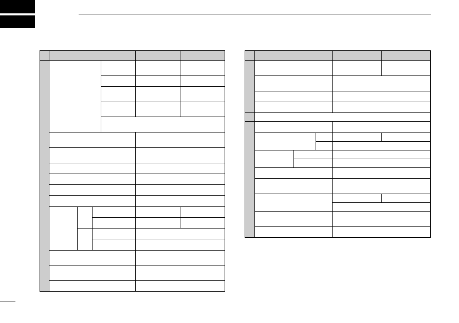
SPECIFICATIONS
13
42
* Specifications guaranteed at a transceiver temperature of +25°C (+77°F).
All stated specifications are subject to change without
notice or obligation.
VHF
TRANSMITTER
Output power*
(at 13.5 V)
5 W, 0.5 W
(selectable)
30.85 MHz
Modulation system
Variable reactance frequency
modulation
Except for
1
⁄
2
of IF and 2nd image freq.
Max. frequency deviation*
±5.0 kHz
More than 50 dB
External microphone jack
2.5 mm (
1
⁄
10
in) 3-conductor/2 k
Ω
5 W, 0.5 W
(selectable)
RECEIVER
Receive system
Double conversion superheterodyne
46.05 MHz
Intermediate
frequencies
1st
450 kHz
Sensitivity*
(12 dB SINAD)
Less than 0.16 µV
Opposite band
Squelch sensitivity
Less than 0.16 µV
2nd
Selectivity
More than 15 kHz/–6 dB
Less than 30 kHz/–60 dB
Original band
Spurious and image
rejection ratio*
More than 60 dB
Less than 0.32 µV
Audio output power*
(at 13.5 V)
More than 180 mW
(at 10% distortion with an 8
Ω
load)
External speaker jack
3.5 mm (
1
⁄
8
in) 3-conductor/8
Ω
UHF
Frequency stability
External DC power
VHF
UHF
GENERAL
Frequency
coverage
(MHz)
4.5 to 16 V DC (negative ground)
U.S.A.
Tx: 144–148
Rx: 118–174*
1
Tx: 440–450
Rx: 400–470*
2
Tx: 430–440
Rx: 400–470*
3
Europe
144–146
430–440
–10°C to +60°C;
+14°F to +140°F
Current
drain
(at 13.5 V,
typical)
See options on page at right.
1.5 A
430–440
Tx: 144–148
Rx: 118–174*
1
Asia
Tx: 144–148
Rx: 136–174*
1
Italy
1.6 A
High
Tx
210 mA
Rated audio
Guaranteed ranges are:
*
1
144–148 *
2
440–450 *
3
430–440
Rx
Power saved
Mode
Low
FM
(U.S.A./Asia versions:
AM Rx 118–136 MHz)
Weight
(with BP-173 and antenna)
500 mA
600 mA
±5 ppm
(0°C to +50°C; +32°F to +122°F)
40 mA
(average)
Dimensions
(with BP-173 or
BP-180; projections not included)
Tuning steps (kHz)
5, 10, 12.5, 15, 20, 25, 30 or 50
57(W)
✕
137(H)
✕
33(D) mm;
2
1
⁄
4
(W)
✕
5
13
⁄
32
(H)
✕
1
5
⁄
16
(D) in
Usable temperature range
Antenna connector
BNC (50
Ω
)
Usable battery pack/case
450 g; 1 lb
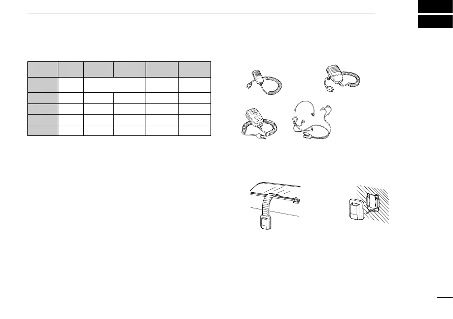
D
Battery packs
OPTIONS
14
43
Bracketed values in the output power column refer to the UHF band. Operating
periods are calibrated for the following conditions:
at 25°C (77°F), Tx (high power) : Rx : standby = 1 : 1 : 8
D
Chargers and cables
BC-110A/D/V WALL CHARGERS
Regularly charge battery packs.
BC-119 DESKTOP CHARGER + AD-51 DESKTOP CHARGER ADAPTER
Rapidly charge battery packs in 1 to 1.5 hrs. depending on the bat-
tery pack. The AD-51 must be used with the BC-119 for charging a
battery pack. Some BC-119 versions require the AD-75 additionally.
The CP-17L or OPC-515L can be used instead of the supplied AC
adapter.
CP-12/L CIGARETTE LIGHTER CABLE WITH NOISE FILTER
For operation and charging via a 12 V cigarette lighter socket.
OPC-254/L DC POWER CABLE
For operation and charging via an external power supply.
D
Carrying case
LC-128 CARRYING CASE
D
Speaker-microphones
D
Others
MB-30 MOUNTING BRACKET
SP-13 EARPHONE
Provides clear receive audio in noisy environments.
CS-W32 CLONING SOFTWARE + OPC-478 CLONING CABLE
Provide quick and easy programming of memory channels, memory
names and set mode contents, etc.
OPC-474 CLONING CABLE
Used for handheld-to-handheld data cloning.
HM-46
HM-75A
HM-54
HS-85 HEADSET
• PTT switch
• VOX
• One-touch PTT for
hands-free operation
When using the bracket hanger
When using no bracket hanger
BATTERY
PACK
HEIGHT
(mm/in)
VOLTAGE CAPACITY
OUTPUT
POWER
OPER.
PERIOD*
BP-170
63.5/2.5
Battery case for
R6(AA)
✕
4 alkaline cells
1.5 (1.3) W
Depends
on battery
BP-171
63.5/2.5
4.8 V
700 mAh 1.5 (1.3) W 5.5 (4.5) h
BP-172
63.5/2.5
4.8 V
950 mAh 1.5 (1.3) W 7.5 (6.0) h
BP-173
75.5/3.0
9.6 V
650 mAh 5.0 (4.5) W 3.5 (3.0) h
BP-180
75.5/3.0
7.2 V
600 mAh 3.5 (3.5) W 3.5 (3.0) h

A-5399Y-1EX-
w
Printed in Japan
Copyright © 1996 by Icom Inc.
6-9-16 Kamihigashi, Hirano-ku, Osaka 547 Japan
Wyszukiwarka
Podobne podstrony:
więcej podobnych podstron