Graphics with GDI+
This is the second of the two chapters in this book that covers the elements of interacting directly with
the user, that is displaying information on the screen and accepting user input via the mouse or
keyboard. In Chapter 9 we focused on Windows Forms, where we learnt how to display a dialog box or
SDI or MDI window, and how to place various controls on it such as buttons, text boxes, and list boxes.
In that chapter, the emphasis was very much on using the familiar predefined controls at a high level
and relying on the fact that these controls are able to take full responsibility for getting themselves
drawn on the display device. Basically, all you need to do is set the controls' properties and add event
handlers for those user input events that are relevant to your application. The standard controls are
powerful, and you can achieve a very sophisticated user interface entirely by using them. Indeed, they
are by themselves quite adequate for the complete user interface for many applications, most notably
dialog-type applications, and those with explorer style user interfaces.
However there are situations in which simply using controls doesn't give you the flexibility you need in your
user interface. For example, you may want to draw text in a given font in a precise position in a window, or
you may want to display images without using a picture box control, simple shapes or other graphics. A good
example, is the Word for Windows program that I am using to write this chapter. At the top of the screen are
various menus and toolbars that I can use to access different features of Word. Some of these menus and
buttons bring up dialog boxes or even property sheets. That part of the user interface is what we covered in
Chapter 9. However, the main part of the screen in Word for Windows is very different. It's an SDI window,
which displays a representation of the document. It has text carefully laid out in the right place and displayed
with a variety of sizes and fonts. Any diagrams in the document must be displayed, and if you're looking at
the document in Print Layout view, the borders of the actual pages need to be drawn in too. None of this can
be done with the controls from Chapter 9. To display that kind of output, Word for Windows must take
direct responsibility for telling the operating system precisely what needs to be displayed where in its SDI
window. How to do this kind of thing is subject matter for this chapter.
We're going to show you how to draw a variety of items including:
❑
Lines, simple shapes.
❑
Images from bitmap and other image files.
❑
Text.

Chapter 21
904
In all cases, the items can be drawn wherever you like within the area of the screen occupied by your
application, and your code directly controls the drawing – for example when and how to update the
items, what font to display text in and so on.
In the process, we'll also need to use a variety of helper objects including pens (used to define the
characteristics of lines), brushes (used to define how areas are filled in – for example, what color the
area is and whether it is solid, hatched, or filled according to some other pattern), and fonts (used to
define the shape of characters of text). We'll also go into some detail on how devices interpret and
display different colors.
The code needed to actually draw to the screen is often quite simple, and it relies on a technology called
GDI+
. GDI+ consists of the set of .NET base classes that are available for the purpose of carrying out
custom drawing on the screen. These classes are able to arrange for the appropriate instructions to be
sent to the graphics device drivers to ensure the correct output is placed on the monitor screen (or
printed to a hard copy). Just as for the rest of the .NET base classes, the GDI+ classes are based on a
very intuitive and easy to use object model.
Although the GDI+ object model is conceptually fairly simple we still need a good understanding of the
underlying principles behind how Windows arranges for items to be drawn on the screen in order to
draw effectively and efficiently using GDI+.
This chapter is broadly divided into two main sections. In the first two-thirds of the chapter we will
explore the concepts behind GDI+ and examine how drawing takes place, which means that this part of
the chapter will be quite theoretical, with the emphasis on understanding the concepts. There will be
quite a few samples, almost all of them very small applications that display specific hard-coded items
(mostly simple shapes such as rectangles and ellipses). Then for the last third of the chapter we change
tack and concentrate on working through a much longer sample, called CapsEditor, which displays
the contents of a text file and allows the user to make some modifications to the displayed data. The
purpose of this sample, is to show how the principles of drawing should be put into practice in a real
application. The actual drawing itself usually requires little code – the GDI+ classes work at quite a high
level, so in most cases only a couple of lines of code are required to draw a single item (for example, an
image or a piece of text). However, a well designed application that uses GDI+ will need to do a lot of
additional work behind the scenes, that is it must ensure that the drawing takes place efficiently, and
that the screen is updated when required, without any unnecessary drawing taking place. (This is
important because most drawing work carries a very big performance hit for applications.) The
CapsEditor
sample shows how you'll typically need to do much of this background management.
The GDI+ base class library is huge, and we will scarcely scratch the surface of its features in this
chapter. That's a deliberate decision, because trying to cover more than a tiny fraction of the classes,
methods and properties available would have effectively turned this chapter into a reference guide that
simply listed classes and so on. We believe it's more important to understand the fundamental principles
involved in drawing; then you will be in a good position to explore the classes available yourself. (Full
lists of all the classes and methods available in GDI+ are of course available in the MSDN
documentation.) Developers coming from a VB background, in particular, are likely to find the concepts
involved in drawing quite unfamiliar, since VB's focus lies so strongly in controls that handle their own
painting. Those coming from a C++/MFC background are likely to be in more comfortable territory
since MFC does require developers to take control of more of the drawing process, using GDI+'s
predecessor, GDI. However, even if you have a good background in GDI, you'll find a lot of the
material is new. GDI+ does actually sit as a wrapper around GDI, but nevertheless GDI+ has an object
model which hides many of the workings of GDI very effectively. In particular, GDI+ replaces GDI's
largely stateful model in which items were selected into a device context with a more stateless one, in
which each drawing operation takes place independently. A Graphics object (representing the device
context) is the only object that persists between drawing operations.
Graphics with GDI+
905
By the way, in this chapter we'll use the terms drawing and painting interchangeably to describe the
process of displaying some item on the screen or other display device.
Before we get started we will quickly list the main namespaces you'll find in the GDI+ base classes.
They are:
Namespace
Contains
System.Drawing
Most of the classes, structs, enums and delegates.
concerned with the basic functionality of drawing.
System.Drawing.Drawing2D
More specialized classes, and so on. that give more
advanced effects in drawing to the screen.
System.Drawing.Imaging
Various classes that assist in the manipulation of images
(bitmaps, GIF files and so on.).
System.Drawing.Printing
Classes to assist when specifically targeting a printer or
print preview window as the output 'device'.
System.Drawing.Design
Some predefined dialog boxes, property sheets and other
user interface elements concerned with extending the
design time user interface.
System.Drawing.Text
Classes to performed more advanced manipulation of
fonts and font families.
Almost all the classes, structs and so on. we use in this chapter will be taken from the System.Drawing
namespace.
Understanding Drawing Principles
In this section, we'll examine the basic principles that we need to understand in order to start drawing to
the screen. We'll start by giving an overview of GDI, the underlying technology on which GDI+ is
based, and see how it and GDI+ are related. Then we'll move on to a couple of simple samples.
GDI and GDI+
In general, one of the strengths of Windows – and indeed of modern operating systems in general – lies
in their ability to abstract the details of particular devices away from the developer. For example, you
don't need to understand anything about your hard drive device driver in order to programmatically
read and write files to disk; you simply call the appropriate methods in the relevant .NET classes (or in
pre-.NET days, the equivalent Windows API functions). This principle is also very true when it comes to
drawing. When the computer draws anything to the screen, it does so by sending instructions to the
video card telling it what to draw and where. The trouble is that there are many hundreds of different
video cards on the market, many of them made by different manufacturers, and most of which have
different instruction sets and capabilities. The way you tell one video card to draw, for example a simple
line or a character string may involve different instructions from how you would tell a different video
card to draw exactly the same thing. If you had to take that into account, and write specific code for
each video driver in an application that drew something to the screen, writing the application would be
an almost impossible task. Which is why the Windows Graphical Device Interface (GDI) has always
been around since the earliest versions of Windows.
Chapter 21
906
GDI hides the differences between the different video cards, so that you simply call the Windows API
function to do the specific task, and internally the GDI figures out how to get your particular video card
to do whatever it is you want drawn. However, GDI also does something else. You see, most computers
have more than one device that output can be sent to. These days you will typically have a monitor,
which you access through the video card and you will also have a printer. Some machines may have
more than one video card installed, or you may have more than one printer. GDI achieves the
remarkable feat of making your printer seem the same as your screen as far as your application is
concerned. If you want to print something instead of displaying it, you simply inform the system that
the device the output is being sent to is the printer and then call the same API functions in exactly the
same way. That's the whole purpose of GDI – to abstract the features of the hardware into a relatively
high level API.
Although GDI exposes a relatively high level API to developers, it is still an API that is based on the old
Windows API, with C-style functions, and so is not as simple to use as it could be. GDI+ to a large
extent sits as a layer between GDI and your application, providing a more intuitive, inheritance-based
object model. Although GDI+ is basically a wrapper around GDI, Microsoft have been able through
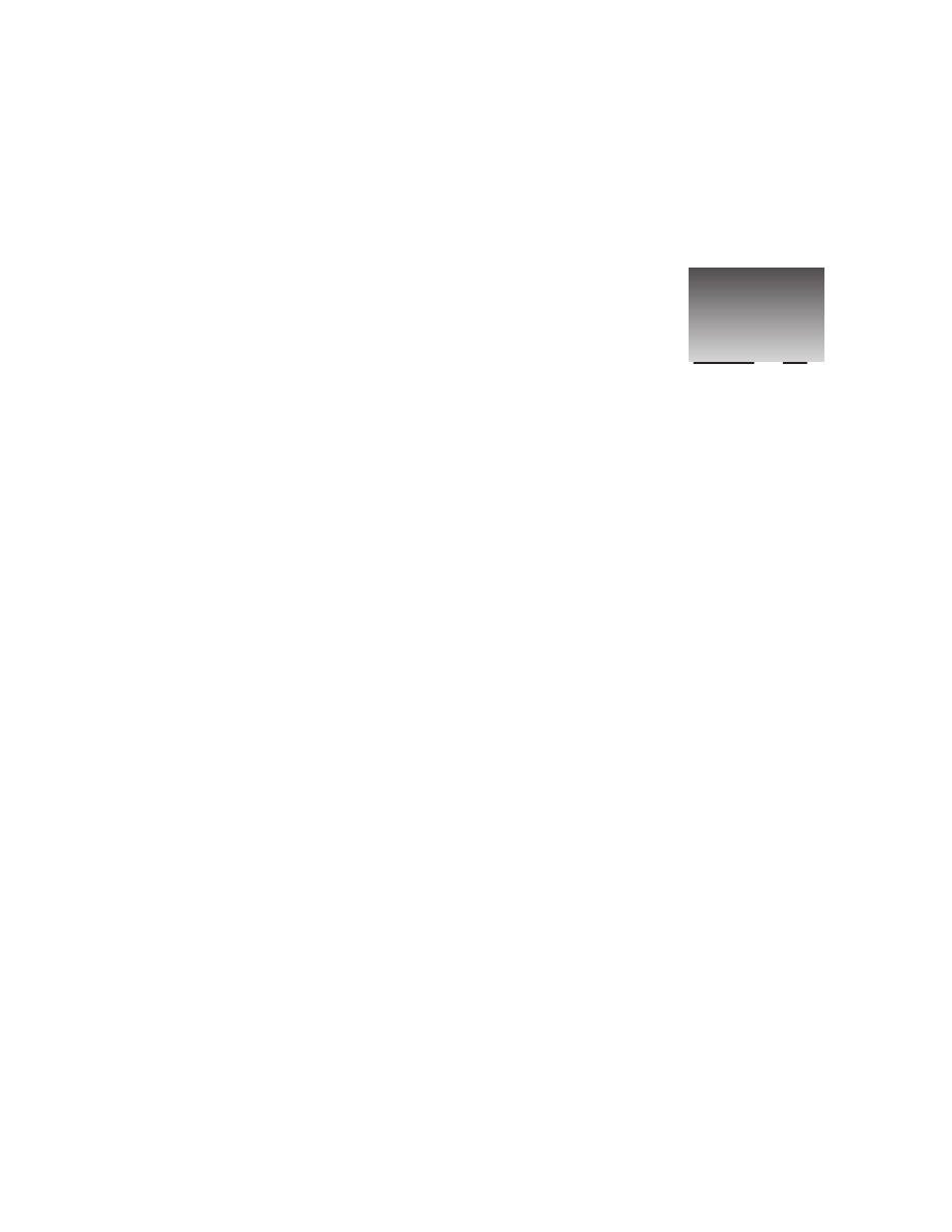
GDI+ to provide new features and claim to have made some performance improvements:
client
real proxy
transparent proxy
envoy sink
Application Domain
Hello()
Invokes()
channel
Process
Message()
Serialize()
formatter
Device Contexts and the Graphics Object
In GDI, the way that you identify which device you want your output to go to is through an object
known as the device context (DC). The device context stores information about a particular device
and is able to translate calls to the GDI API functions into whatever instructions need to be sent to that
device. You an also query the device context to find out what the capabilities of the corresponding
device are (for example, whether a printer print in color or only black and white), so you can adjust
your output accordingly. If you ask the device to do something it's not capable of, the device context
will normally detect this, and take appropriate action (which depending on the situation might mean
throwing an error or it might mean modifying the request to get the closest match to what the device is
actually capable of).
However, the device context doesn't only deal with the hardware device. It acts as a bridge to Windows,
and is therefore, able to take account of any requirements or restrictions placed on the drawing by
Windows. For example, if Windows knows that only a portion of your application's window needs to be
redrawn (perhaps because you've minimized another window that had been hiding part of your
application), the device context can trap and nullify attempts to draw outside that area. Due to the

Graphics with GDI+
907
device context's relationship with Windows, working through the device context can simplify your code
in other ways. For example, hardware devices need to be told where to draw objects, and they usually
want coordinates relative to the top left corner of the screen (or output device). Usually however, your
application will be thinking of drawing something at a certain position within the client area of its own
window. (The client area of a Window is the part of the window that's normally used for drawing –
which normally means the window with the borders excluded; on many applications the client area will
be the area that has a white background.) However, since the window might be positioned anywhere on
the screen, and a user might move it at any time, translating between the two coordinates is potentially a
difficult task. However, the device context always knows where your window is and as able to perform
this translation automatically. This means that you can just ask the device context to get an item drawn
at a certain position within your window, without needing to worry about where on the screen your
application's window is currently located.
As you can see, the device context is a very powerful object and you won't be surprised to learn that
under GDI all drawing had to be done through a device context. You even sometimes use the device
context for operations that don't involve drawing to the screen or to any hardware device. For example,
if you have an image such as a bitmap to which you are making some modifications (perhaps resizing
it), it's more efficient to do so via a device context because the device context may be able to take
advantage of certain hardware features of your machine in order to carry out such operations more
quickly. Although modifying images is beyond the scope of this chapter, we'll note that device contexts
can be used to prepare images in memory very efficiently, before the final result is sent to the screen.
With GDI+, the device context is still there, although it's now been given a more friendly name. It is
wrapped up in the .NET base class, Graphics. You'll find that, as we work through the chapter, most
drawing is done by calling methods on an instance of Graphics. In fact, since the
System.Drawing.Graphics
class is the class that is responsible for actually handling most drawing
operations, very little gets done in GDI+ that doesn't involve a Graphics instance somewhere.
Understanding how to manipulate this object is the key to understanding how to draw to display devices
with GDI+.
Sample: Drawing Shapes
We're going to start off with a short sample to illustrate drawing to an application's main window. The
samples in this chapter, are all created in Visual Studio.NET as C# Windows applications. Recall that
for this type of project the code wizard gives us a class called Form1, derived from
System.Windows.Form
, which represents the application's main window. Unless otherwise stated, in
all samples, new or modified code means code that we've added to this class.
In .NET usage, when we are talking about applications that display various controls, the
terminology form has largely replaced window to represent the rectangular object that occupies an
area of the screen on behalf of an application. In this chapter, we've tended to stick to the term
window, since in the context of manually drawing items it's rather more meaningful. We write
Windows (capital W) when we are referring to the operating system, and windows (small w) to
refer to windows on the screen. We'll also talk about the Form when we're referring to the .NET
class used to instantiate the form/window.
The first sample, will simply create a form and draw to it in the InitializeComponent() method. I
should say at the start that this is not actually the best way to draw to the screen – we'll quickly find that
this sample has a problem in that it is unable to redraw anything when it needs to after starting up.
However the sample will illustrate quite a few points about drawing without our having to do very much
work.

Chapter 21
908
For this sample, we start Visual Studio.NET, create a Windows application, and modify the code in the
InitializeComponent()
method as follows:
private void InitializeComponent()
{
this.components = new System.ComponentModel.Container();
this.Size = new System.Drawing.Size(300,300);
this.Text = "Display At Startup";
this.BackColor = Color.White;
and we add the following code to the Form1 constructor:
public Form1()
{
InitializeComponent();
Graphics dc = this.CreateGraphics();
this.Show();
Pen BluePen = new Pen(Color.Blue, 3);
dc.DrawRectangle(BluePen, 0,0,50,50);
Pen RedPen = new Pen(Color.Red, 2);
dc.DrawEllipse(RedPen, 0, 50, 80, 60);
}
Those are the only changes we make. This sample is the DisplayAtStartup sample from the code
download.
We set the background color of the form to white – so it looks like a 'proper' window that we're going to
display graphics in! We've put this line in the InitializeComponent() method, so that Visual
Studio.NET recognizes the line and is able to alter the design view appearance of the form.
Alternatively, we could have used the design view to set the background color, which would have
resulted in the same statement appearing in InitializeComponent(). Recall that this method is the
one used by Visual Studio.NET to establish the appearance of the form. If we don't set the background
color explicitly, it will remain as the default color for dialog boxes – whatever color is specified in your
Windows settings.
Next, we create a Graphics object using the Form's CreateGraphics() method. This Graphics
object contains the Windows device context we need to draw with. The device context created is
associated with the display device, and also with this window. Notice, that we've used the variable name
dc
for the Graphics object instance, reflecting the fact that it really represents a device context behind
the scenes.
We then call the Show() method to display the window. This is really a fudge to force the window to
display immediately, because we can't actually do any drawing until the window has been displayed –
there's nothing to draw onto.
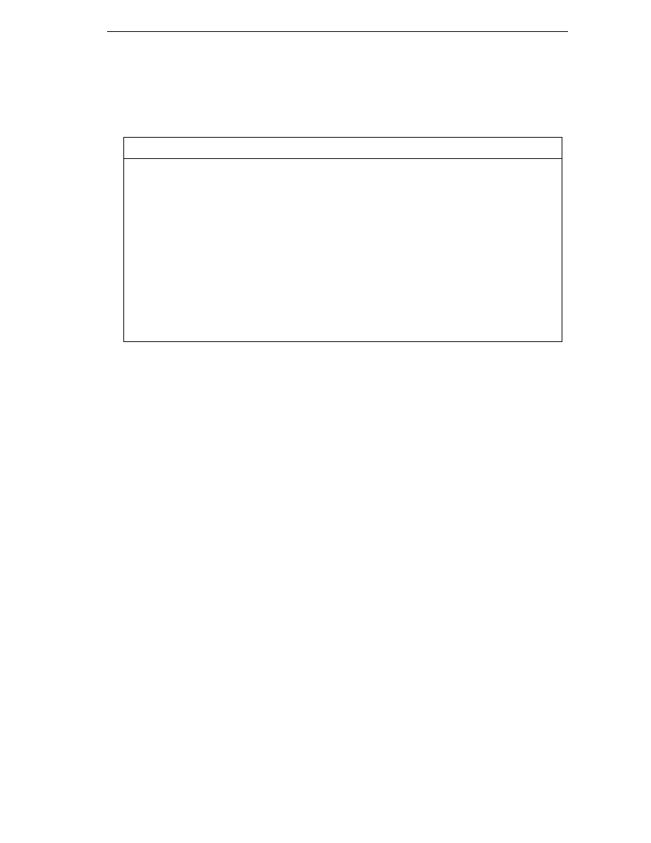
Finally, we display a rectangle, at coordinates (0,0), and with width and height 50, and an ellipse with
coordinates (0, 50) and with width 80 and size 50. Note that coordinates (x, y) means x pixels to the
right and y pixels down from the top left corner of the client area of the window – and these are the
coordinates of the top left corner of the shape being displayed:
Graphics with GDI+
909
CLIENT AREA OF WINDOW
x pixels across
Point (x,y)
y pixels down
The notation (x,y) is standard mathematical notation and is very convenient for describing coordinates.
The overloads that we are using of the DrawRectangle() and DrawEllipse()methods each take 5
parameters. The first parameter of each is an instance of the class System.Drawing.Pen. A Pen is one
of a number of supporting objects to help with drawing – it contains information about how lines are to
be drawn. Our first pen says that lines should be blue and with a width of 3 pixels, the second says that
lines should be red and have a width of 2 pixels. The final four parameters are coordinates. For the
rectangle, they represent the (x,y) coordinates of the top left hand corner of the rectangle, and its the
width and height, all expressed in terms of numbers of pixels. For the ellipse these numbers represent
the same thing, except that we are talking about a hypothetical rectangle that the ellipse just fits into,
rather than the ellipse itself.
We'll go into more detail about these new structs and the methods of the Graphics object later in
the chapter. For now, we'll just worry about getting something drawn!
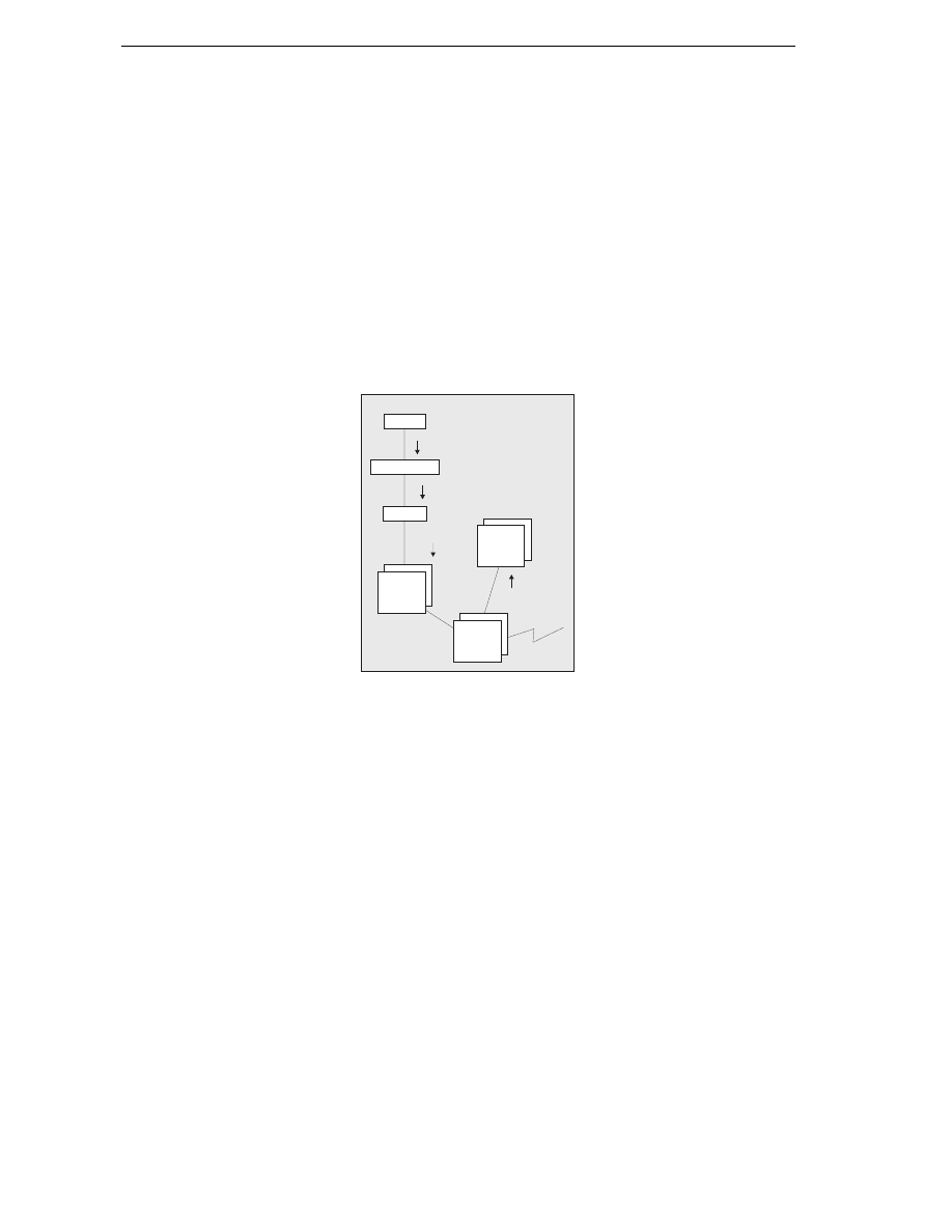
Running this code gives this result:
I know – the book's printed in greyscale. As with all the screenshots in this chapter, you'll just have to
take my word for it that the colors are correct. Or you can always try running the samples yourself!
This screenshot demonstrates a couple of points. First, you can see clearly what is meant by the client
area of the window. It's the white area – the area that has been affected by our setting the BackColor
property. And notice that the rectangle nestles up in the corner of this area, as you'd expect when we
specified coordinates of (0,0) for it. Second, notice how the top of the ellipse overlaps the rectangle
slightly, which you wouldn't expect from the coordinates we gave in the code. That results from where
Windows places the lines that border the rectangle and ellipse. By default, Windows will try to centre

Chapter 21
910
the line on where the border of the shape is – that's not always possible to do exactly, because the line
has to be drawn on pixels (obviously), but the border of each shape theoretically lies between two
pixels. The result is that lines that are 1 pixel thick will get drawn just inside the top and left sides of a
shape, but just outside the bottom and right sides – which means that shapes that strictly speaking are
next to each other will have their borders overlap by one pixel. We've specified wider lines, therefore
the overlap is greater. It is possible to change the default behaviour by setting the Pen.Alignment
property, as detailed in the MSDN documentation, but for our purposes the default behaviour is
adequate.
The screenshot also looks like our code has worked fine. Seems like drawing couldn't be simpler!
Unfortunately, if you actually run the sample you'll notice the form behaves a bit strangely. It's fine if
you just leave it there, and it's fine if you drag it around the screen with the mouse. Try minimizing it
then restoring it however and our carefully drawn shapes just vanish! The same thing happens if you
drag another window across the sample. Even more interestingly, if you drag another window across it
so that it only obscures a portion of our shapes, then drag the other window away again, you'll find the
temporarily obscured portion has disappeared and you're left with half an ellipse or half a rectangle!
So what's going on? Well the problem arises, because if a window or part of a window gets hidden for
any reason (for example, it is minimized or hidden by another window), Windows usually immediately
discards all the information concerning exactly what was being displayed there. It has to – otherwise the
memory usage for storing screen data would be astronomical. Think about it. A typical computer might
be running with the video card set to display 1024 x 768 pixels, perhaps with 24-bit color mode. We'll
cover what 24-bit color means later in the chapter, but for now I'll say that implies that each pixel on
the screen occupies 3 bytes. That means 2.25MB to display the screen. However, it's not uncommon for
a user to sit there working, with 10 or 20 minimized windows in the taskbar. Let's do a worst-case
scenario: 20 windows, each one would occupy the whole screen if it wasn't minimized. If Windows
actually stored the visual information those windows contained, ready for when the user restored them,
you'd be talking about 45MB! These days, a good graphics card might have 64MB of memory and be
able to cope with that, but it's only a couple of years ago that 4MB was considered generous in a
graphics card – and the excess would need to be stored in the computer's main memory. A lot of people
still have old machines (I still use a spare computer that has a 2 MB graphics card). Clearly it wouldn't
be practical for Windows to manage its user interface like that.
The moment any part of a window gets hidden, those pixels get lost. What happens is that Windows just
makes a note that the window (or some portion of the window) is hidden, and when it detects that that
area is no longer hidden, it asks the application that owns the window to redraw its contents. There are
a couple of exceptions to this rule – generally for cases in which a small portion of a window is hidden
very temporarily (a good example is when you select an item from the main menu and that menu item
drops down, temporarily obscuring part of the window below). In general however, you can expect that
if part of your window gets hidden, your application will need to redraw it later.
That's a problem for our sample application. We placed our drawing code in the Form1 constructor,
which is called just once when the application starts up, and you can't call the constructor again to
redraw the shapes when required later on.
In Chapter 9, when we covered controls, we didn't need to know about any of that. This is because the
standard controls are pretty sophisticated and they are able to redraw themselves correctly whenever
Windows asks them to. That's one reason why when programming controls you don't need to worry
about the actual drawing process at all. If we are taking responsibility for drawing to the screen in our
application then we also need to make sure our application will respond correctly whenever Windows
asks it to redraw all or part of its window. In the next section, we will modify our sample to do just that.

Graphics with GDI+
911
Painting Shapes using OnPaint
If the above explanation has made you worried that drawing your own user interface is going to be
terribly complicated, don't worry. It isn't. I went into a lot of detail about the process, because it's
important to understand what the issues you will face are, but getting your application to redraw itself
when necessary is actually quite easy.
What happens, is that Windows notifies an application that some repainting needs to be done by raising
a Paint event. Interestingly, the Form class has already implemented a handler for this event so you
don't need to add one yourself. You can feed into this architecture by using the fact that the Form1
handler for the Paint event will some point in its processing calls up a virtual method OnPaint(),
passing to it a single PaintEventArgs parameter. This means that all we need to do is override
OnPaint()
to perform our painting. We'll create a new sample, called DrawShapes to do this. As
before, DrawShapes as a Visual Studio.NET-generated Windows application, and we add the following
code to the Form1 class:
protected override void OnPaint( PaintEventArgs e )
{
Graphics dc = e.Graphics;
Pen BluePen = new Pen(Color.Blue, 3);
dc.DrawRectangle(BluePen, 0,0,50,50);
Pen RedPen = new Pen(Color.Red, 2);
dc.DrawEllipse(RedPen, 0, 50, 80, 60);
base.OnPaint( e );
}
Notice that OnPaint() is declared as protected. OnPaint() is normally internally within the class,
so there's no reason for any other code outside the class to know about its existence.
PaintEventArgs
is a class that is derived from the EventArgs class normally used to pass in
information about events. PaintEventArgs has two additional properties, of which the most important
is a Graphics instance, already primed and optimised to paint the required portion of the window.
This means that you don't have to call CreateGraphics() to get a device context in the OnPaint()
method – you've already been provided with one. We'll look at the other additional property soon – it
contains more detailed information about which area of the window actually needs repainting.
In our implementation of OnPaint(), we first get a reference to the Graphics object from
PaintEventArgs
, then we draw our shapes exactly as we did before. At the end we call the base
classes' OnPaint() method. This step is important. We've overridden OnPaint() to do our own
painting, but it's possible that Windows may have some additional work of its own to do in the painting
process – any such work will be dealt with in an OnPaint() method in one of the .NET base classes.
For this sample, you'll find that removing the call to base.OnPaint() doesn't seem to have any
effect, but don't ever by tempted to leave this call out. You might be stopping Windows from doing
its work properly and the results could be unpredictable.
OnPaint()
will also be called when the application first starts up and our window is displayed for the
first time, so there is no need to duplicate the drawing code in the constructor, though we still need to
set the background color there along with any other properties of the form. Again we can do this either
by adding the command explicitly or by setting the color in the Visual Studio.NET properties window:
Chapter 21
912
private void InitializeComponent()
{
this.components = new System.ComponentModel.Container();
this.Size = new System.Drawing.Size(300,300);
this.Text = "Draw Shapes";
this.BackColor = Color.White;
}
Running this code gives the same results initially as for our previous sample – except that now our
application behaves itself properly when you minimize it or hide parts of the window.
Using the Clipping Region
Our DrawShapes sample from the last section illustrates the main principles involved with drawing to a
window, however it's not very efficient. The reason is that it attempts to draw everything in the window,
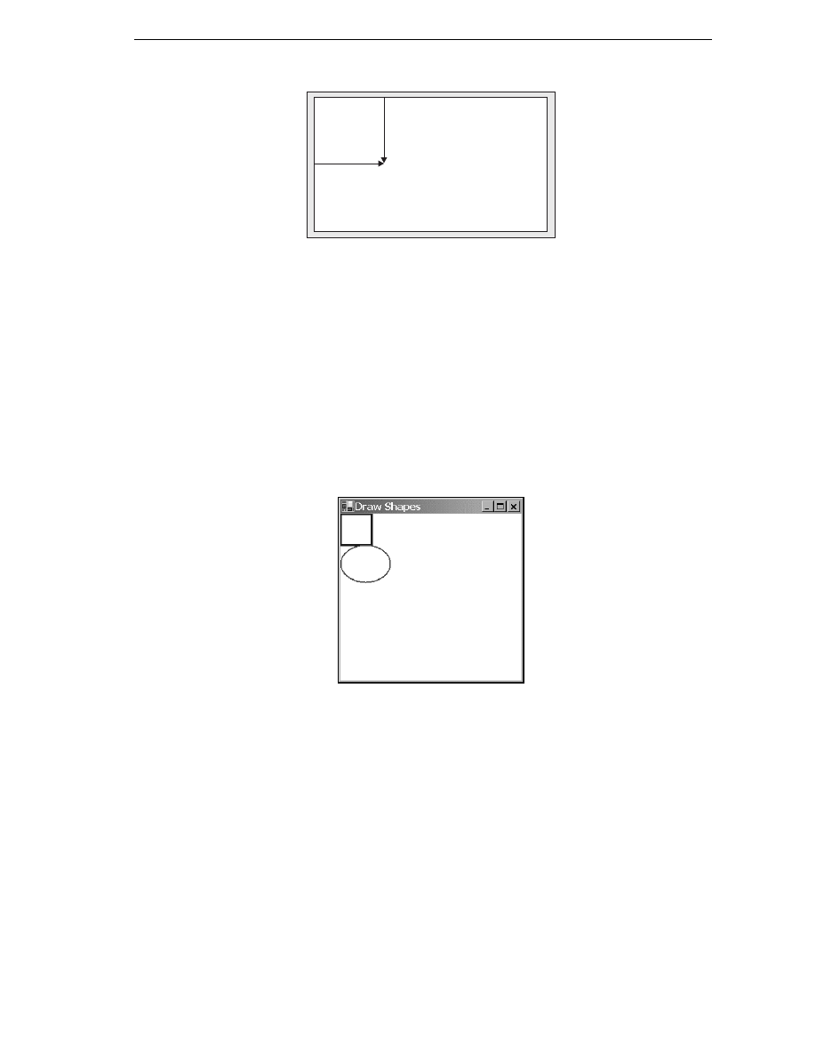
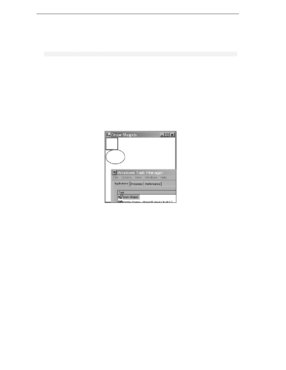
irrespective of how much needs to be drawn. Consider the situation shown in this figure. I ran the
DrawShapes
sample, but while it was on the screen I opened another window and moved it over the
DrawShapes
form, so it hid part of it. The other window here happens to be the Windows 2000 Task
Manager but it doesn't matter what the other window is; the principle is the same:
So far so good. What will happen however when I move the overlapping window (in this case the task
manager) so that the DrawShapes window is fully visible again? Well, Windows will as usual send a
Paint
event to the form, asking it to repaint itself. The rectangle and ellipse both lie in the top left
corner of the client area, and so were visible all the time therefore, there's actually nothing that needs to
be done in this case apart from repaint the white background area. However, Windows doesn't know
that. As far as Windows is concerned, part of the window needs to be redrawn, and that means we need
to raise the Paint event, resulting in our OnPaint() implementation being called. OnPaint() will
then unnecessarily attempt to redraw the rectangle and ellipse.
In this case, the shapes will not get repainted. The reason is to do with the device context. Remember
that I said that the device context inside the Graphics object passed to OnPaint() will have been
optimized by Windows to the particular task at hand? What this means, is that Windows has pre-
initialized the device context with information concerning what area actually needed repainting. This is
the rectangle that was covered with the Task Manager window in the screenshot above. In the days of
GDI, the region that is marked for repainting used to be known as the invalidated region, but with
GDI+ the terminology has largely changed to clipping region. The device context knows what

Graphics with GDI+
913
this region is therefore, it will intercept any attempts to draw outside this region, and not pass the
relevant drawing commands on to the graphics card. That sounds good, but there's still a potential
performance hit here. We don't know how much processing the device context had to do before it
figured out that the drawing was outside the invalidated region. In some cases it might be quite a lot,
since calculating which pixels need to be changed to what color can be very processor-intensive
(although a good graphics card will provide hardware acceleration to help with some of this). A
rectangle is quite easy. An ellipse is harder because the position of the curve needs to be calculated.
Displaying text takes a lot of work – the information in the font needs to be processed to figure out the
shape of each letter, and each letter will be composed of a number of lines and curves which need to be
drawn individually. If, like most common fonts, it's a variable width font, that is, each letter doesn't take
up a fixed size, but takes up however much space it needs, then you can't even work out how much
space the text will occupy without doing quite a few calculations first.
The bottom line to this is that asking the Graphics instance to do some drawing outside the invalidated
region is almost certainly wasting processor time and slowing your application down. In a well
architectured application, your code will actively help the device context out by carrying out a few
simple checks, to see if the usual drawing work is actually needed, before it calls the relevant Graphics
instance methods. In this section we're going to code up a new sample – DrawShapesWithClipping –
by modifying the DisplayShapes sample to do just that. In our OnPaint() code, we'll do a simple
test to see whether the invalidated region intersects the area we need to draw in, and only call the
drawing methods if it does.
First, we need to obtain the details of the clipping region. This is where an extra property on the
PaintEventArgs
comes in. The property is called ClipRectangle, and it contains the coordinates of
the region to be repainted, wrapped up in an instance of a struct, System.Drawing.Rectangle.
Rectangle
is quite a simple struct – it contains 4 properties of interest: Top, Bottom, Left, and
Right
. These respectively contain the vertical co-ordinates of the top and bottom of the rectangle, and
the horizontal coordinates of the left and right edges.
Next, we need to decide what test we'll use to determine whether drawing should take place. We'll go
for a simple test here. Notice, that in our drawing, the rectangle and ellipse are both entirely contained
within the rectangle that stretches from point (0,0) to point (80,130) of the client area, actually, point
(82,132) to be on the safe side since we know that the lines may stray a pixel or so outside this area. So
we'll check whether the top left corner of the clipping region is inside this rectangle. If it is, we'll go
ahead and draw. If it isn't, we won't bother.
The code to do this looks like this:
protected override void OnPaint( PaintEventArgs e )
{
Graphics dc = e.Graphics;
if (e.ClipRectangle.Top < 132 && e.ClipRectangle.Left < 82)
{
Pen BluePen = new Pen(Color.Blue, 3);
dc.DrawRectangle(BluePen, 0,0,50,50);
Pen RedPen = new Pen(Color.Red, 2);
dc.DrawEllipse(RedPen, 0, 50, 80, 60);
}
base.OnPaint(e);
}
Chapter 21
914
Note that what gets displayed is exactly the same as before – but performance is improved now by the
early detection of some cases in which nothing needs to be drawn. Notice, also that we've chosen a
fairly crude test of whether to proceed with the drawing. A more refined test might be to check
separately, whether the rectangle needs to be drawn or whether the ellipse needs to be redrawn, or
both. There's a balance here. You can make your tests in OnPaint() more sophisticated – as you do,
you'll improve performance, but you'll also make your own OnPaint() code more complex and create
more work for yourself. How far you go is up to you. It's almost always worth putting some test in
however, simply because you've got the benefit of understanding the broad picture of what it is you are
drawing (for example, in our example we have the advance knowledge that nothing we draw will ever
go outside the rectangle (0,0) to (82,132)). The Graphics instance doesn't have that understanding – it
blindly follows drawing commands. That extra knowledge means you may be able to code up more
useful or efficient tests than the Graphics instance could possibly do.
Measuring Coordinates and Areas
In our last example, we encountered the base struct, Rectangle, which is used to represent the
coordinates of a rectangle. GDI+ actually uses several similar structures to represents coordinates or
areas, and we're at a convenient point in the chapter to go over the main ones. We'll look at the
following structs, which are all defined in the System.Drawing namespace:
Struct
Main Public Properties
struct Point
struct PointF
X, Y
struct Size
struct SizeF
Width, Height
struct Rectangle
struct RectangleF
Left, Right, Top, Bottom, Width, Height, X,
Y, Location, Size
Note that many of these objects have a number of other properties, methods, or operator overloads not
listed here. In this section we'll just discuss the most important ones.
Point and PointF
We'll look at Point first. Point is conceptually the simplest of these structs. Mathematically, it's
completely equivalent to a 2D vector. It contains two public integer properties, which represent how far
you move horizontally and vertically from a particular location (perhaps on the screen). In other words,
look at this diagram:
Point A
20 units
Point B
10 units
X
Y

Graphics with GDI+
915
In order to get from point A to point B, you move 20 units across and 10 units down, marked as x and y
on the diagram as this is how they are commonly referred to. We could create a Point struct that
represents that as follows:
Point AB = new Point(20, 10);
Console.WriteLine("Moved {0} across, {1} down", AB.X, AB.Y);
X and Y are read-write properties, which means you can also set the values in a Point like this:
Point AB = new Point();
AB.X = 20;
AB.Y = 10;
Console.WriteLine("Moved {0} across, {1} down", AB.X, AB.Y);
Note that although conventionally, horizontal and vertical coordinates are referred to as x and y
coordinates (lowercase), the corresponding Point properties are X and Y (uppercase) because the usual
convention in C# is for public properties to have names that start with an uppercase letter.
PointF
is essentially identical to Point, except that X and Y are of type float instead of int. PointF
is used when the coordinates are not necessarily integer values. Casts have been defined for these
structs, so that you can implicitly convert from Point to PointF and explicitly from PointF to Point
– this last one is explicit, because of the risk of rounding errors:
PointF ABFloat = new PointF(20.5F, 10.9F);
Point AB = (Point)ABFloat;
PointF ABFloat2 = AB;
One last point about the coordinates. In this discussion of Point and PointF, I've deliberately been a
bit vague about the units. Am I talking 20 pixels across, 10 pixels down, or do I mean 20 inches or 20
miles? The answer is that how you interpret the coordinates is up to you.
By default, GDI+ will interpret units as pixels along the screen (or printer, whatever the graphics device
is) – so that's how the Graphics object methods will view any coordinates that they get passed as
parameters. For example, the point new Point(20,10) represents 20 pixels across the screen and 10
pixels down. Usually these pixels will be measured from the top left corner of the client area of the
window, as has been the case in our examples up to now. However, that won't always be the case – for
example, on some occasions you may wish to draw relative to the top left corner of the whole window
(including its border), or even to the top left corner of the screen. In most cases however, unless the
documentation tells you otherwise, you can assume you're talking pixels relative to the top left corner of
the client area.
We'll have more to say on this subject later on, after we've examined scrolling, when we mention the
three different coordinate systems in use, world, page, and device coordinates.

Chapter 21
916
Size and SizeF
Like Point and PointF, sizes come in two varieties. The Size struct is for when you are using ints,
SizeF
is available if you need to use floats. Otherwise Size and SizeF are identical. We'll focus on
the Size struct here.
In many ways the Size struct is identical to the Point struct. It has two integer properties that
represent a distance horizontally and a distance vertically – the main difference is that instead of X and
Y, these properties are named Width and Height. We can represent our earlier diagram by:
Size AB = new Size(20,10);
Console.WriteLine("Moved {0} across, {1} down", AB.Width, AB.Height);
Although strictly speaking, a Size mathematically represents exactly the same thing as a Point;
conceptually it is intended to be used in a slightly different way. A Point is used when we are talking
about where something is, and a Size is used when we are talking about how big it is.
As an example, think about the rectangle we drew earlier, with top left coordinate (0,0) and size (50,50):
Graphics dc = e.Graphics;
Pen BluePen = new Pen(Color.Blue, 3);
dc.DrawRectangle(BluePen, 0,0,50,50);
The size of this rectangle is (50,50) and might be represented by a Size instance. The bottom right
corner is also at (50,50), but that would be represented by a Point instance. To see the difference,
suppose we drew the rectangle in a different location, so it's top left coordinate was at (10,10).
dc.DrawRectangle(BluePen, 10,10,50,50);
Now the bottom right corner is at coordinate (60,60), but the size is unchanged – that's still (50,50).
The addition operator has been overloaded for points and sizes, so that it is possible to add a size to a
point giving another point:
static void Main(string[] args)
{
Point TopLeft = new Point(10,10);
Size RectangleSize = new Size(50,50);
Point BottomRight = TopLeft + RectangleSize;
Console.WriteLine("TopLeft = " + TopLeft);
Console.WriteLine("BottomRight = " + BottomRight);
Console.WriteLine("Size = " + RectangleSize);
}

Graphics with GDI+
917
This code, running as a simple console application, produces this output:
Notice that this output also shows how the ToString() method of Point and Size has been
overridden to display the value in {X,Y} format.
Similarly, it is also possible to subtract a Size from a Point to give a Point, and you can add two
Sizes
together, giving another Size. It is not possible however, to add a Point to another Point.
Microsoft decided that adding Points doesn't conceptually make sense, so they chose not supply any
overload to the + operator that would have allowed that.
You can also explicitly cast a Point to a Size and vice versa:
Point TopLeft = new Point(10,10);
Size S1 = (Size)TopLeft;
Point P1 = (Point)S1;
With this cast S1.Width is assigned the value of TopLeft.X, and S1.Height is assigned the value of
TopLeft.Y
. Hence, S1 contains (10,10). P1 will end up storing the same values as TopLeft.
Rectangle and RectangleF
These structures represent a rectangular region (usually of the screen). Just as with Point and Size,
we'll just consider the Rectangle struct here. RectangleF is basically identical except that those of its
properties that represent dimensions all use float, whereas those of Rectangle use int.
A Rectangle can be thought of as composed of a point, representing the top left corner of the
rectangle, and a Size, which represents how large it is. One of its constructors actually takes a Point
and a Size as its parameters. We can see this by rewriting our earlier code to draw a rectangle:
Graphics dc = e.Graphics;
Pen BluePen = new Pen(Color.Blue, 3);
Point TopLeft = new Point(0,0);
Size HowBig = new Size(50,50);
Rectangle RectangleArea = new Rectangle(TopLeft, HowBig);
dc.DrawRectangle(BluePen, RectangleArea);
Chapter 21
918
This code also uses an alternative override of Graphics.DrawRectangle(), which takes a Pen and a
Rectangle
struct, as its parameters.
You can also construct a Rectangle by supplying the top left horizontal coordinate, top left vertical
coordinate, width and height separately and in that order, as individual numbers:
Rectangle RectangleArea = new Rectangle(0, 0, 50, 50)
Rectangle makes quite a few read-write properties available to set or extract its dimensions in different
combinations:
Property
Description
int Left
x-coordinate of left hand edge
int Right
x-coordinate of right hand edge
int Top
y-coordinate of top
int Bottom
y-coordinate of bottom
int X
same as Left
int Y
same as Top
int Width
width of rectangle
int Height
height of rectangle
Point Location
top-left corner
Size Size
size of rectangle
Note that these properties are not all independent – for example setting Width will also affect the
value of Right.
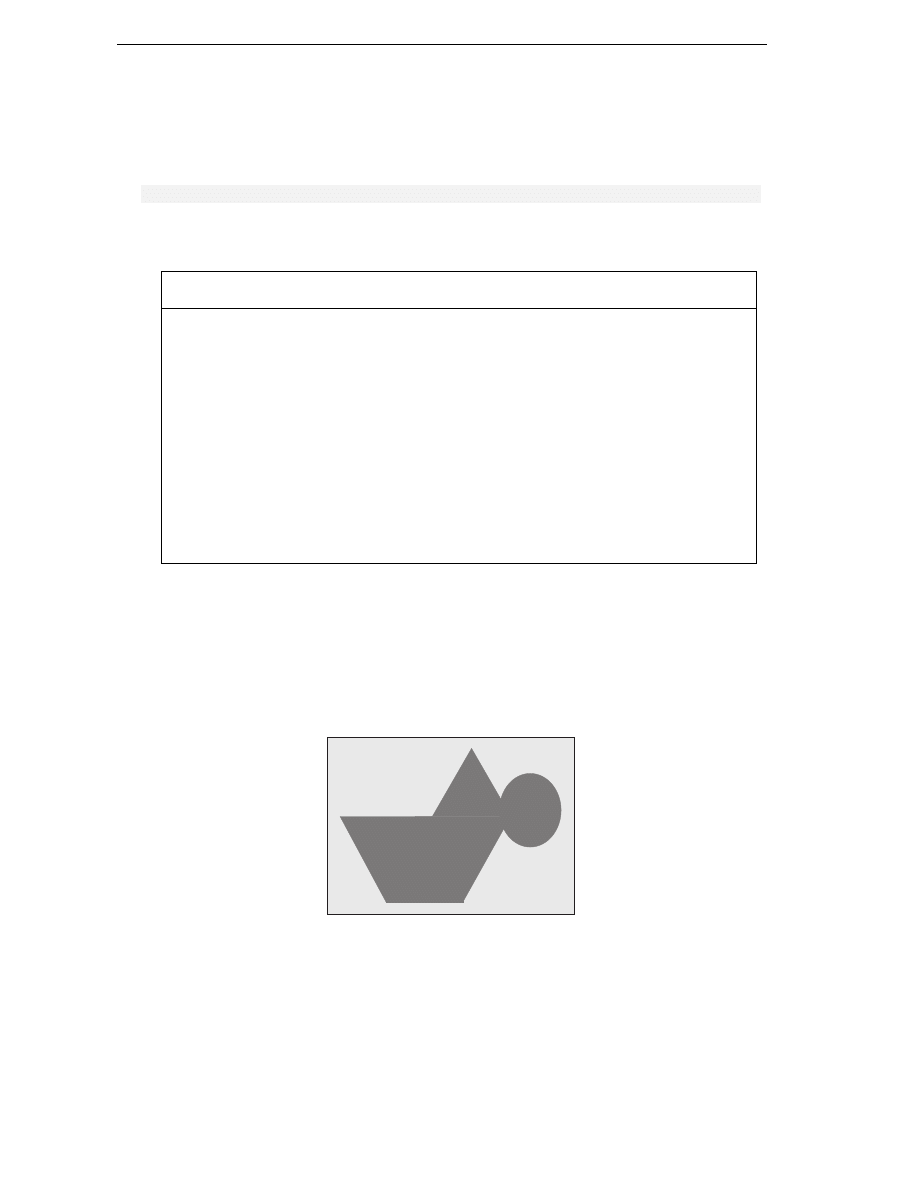
Region
We'll mention the existence of the System.Drawing.Region class here, though we don't have space
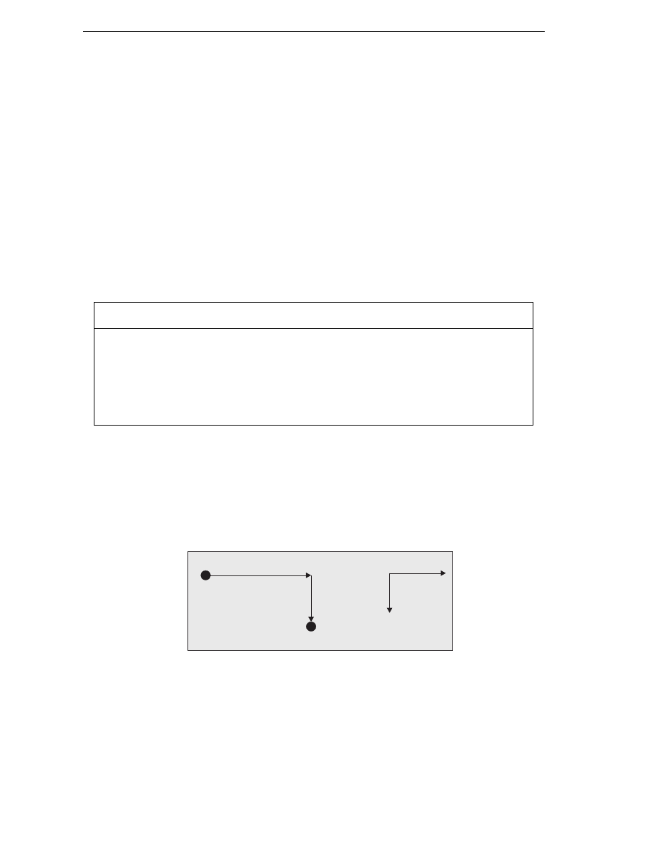
to go details in this book. Region represents an area of the screen that has some complex shape. For
example the shaded area in the diagram could be represented by Region:

Graphics with GDI+
919
As you can imagine, the process of initializing a Region instance is itself quite complex. Broadly
speaking, you can do it by indicating either what component simple shapes make up the region or what
path you take as you trace round the edge of the region. If you do need to start working with areas like
this, then it's worth looking up the Region class.
A Note About Debugging
We're just about ready to do some more advanced drawing now. First however, I just want to say a few
things about debugging. If you have a go at setting break points the samples in this chapter you will
quickly notice that debugging drawing routines isn't quite a simple as debugging other parts of your
program. This is because the very fact of entering and leaving the debugger often causes Paint
messages to be sent to your application. The result can be that setting a breakpoint in your OnPaint
override simply causes your application to keep the painting itself over and over again, so it's unable to
do anything else.
A typical scenario is this. You want to find out why your application is displaying something incorrectly,
so you set a break point in OnPaint. As expected, the application hits the break point and the debugger
comes in, at which point your developer environment MDI window comes to the foreground. If you're
anything like, me you probably have the developer environments set to full screen display so you can
more easily view all the debugging information, which means it always completely hides the application
you are debugging.
Moving on, you examine the values of some variables and hopefully find out something useful. Then
you hit F5 to tell the application to continue, so that you can go on to see what happens when the
application displays something else, after it's done some processing. Unfortunately, the first thing that
happens is that the application comes to the foreground and Windows efficiently detects that the form is
visible again and promptly sends it a Paint event. This means, of course, that your break point gets hit
again straight away. If that's what you want fine, but more commonly what you really want is to hit the
breakpoint later, when the application is drawing something more interesting, perhaps after you've
selected some menu option to read in a file or in some other way change what is displayed. It looks like
you're stuck. Either you don't have a break point in OnPaint at all, or your application can never get
beyond the point where it's displaying its initial startup window.
There are a couple of ways around this problem.
If you have a big enough screen the easiest way is simply to keep your developer environment window
restored rather than maximized and keep it well away from your application window – so your
application never gets hidden in the first place. Unfortunately, in most cases that is not a practical
solution, because that would make your developer environment window too small. An alternative that
uses the same principle is to have your application declare itself as the topmost application while you
are debugging. You do this by setting a property in the Form class, TopMost, which you can easily do
in the InitializeComponent method:
private void InitializeComponent()
{
this.TopMost = true;
This means your application can never be hidden by other windows (except other topmost windows). It
always remains above other windows even when another application has the focus. This is how the task
manager behaves.

Chapter 21
920
Even with this technique you have to be careful, because you can never quite be certain when Windows
might decide for some reason to raise a Paint event. If you really want to trap some problem in that
occurs in OnPaint for some specific circumstance (for example, the application draws something after
you select a certain menu option, and something goes wrong at that point), than the best way to do this
is to place some dummy code in OnPaint that tests some condition, which will only be true in the
specified circumstances – and then place the break point inside the if block, like this:
protected override void OnPaint( PaintEventArgs e )
{
// Condition() evaluates to true when we want to break
if ( Condition() == true)
{
int ii = 0;
// <-- SET BREAKPOINT HERE!!!
}
This is a quick-and-easy way of putting in a conditional break point.
Drawing Scrollable Windows
Our earlier DrawShapes sample worked very well, because everything we needed to draw fitted into
the initial window size. In this section we're going to look at what we need to do if that's not the case.
We shall expand our DrawShapes sample to demonstrate scrolling. To make things a bit more realistic,
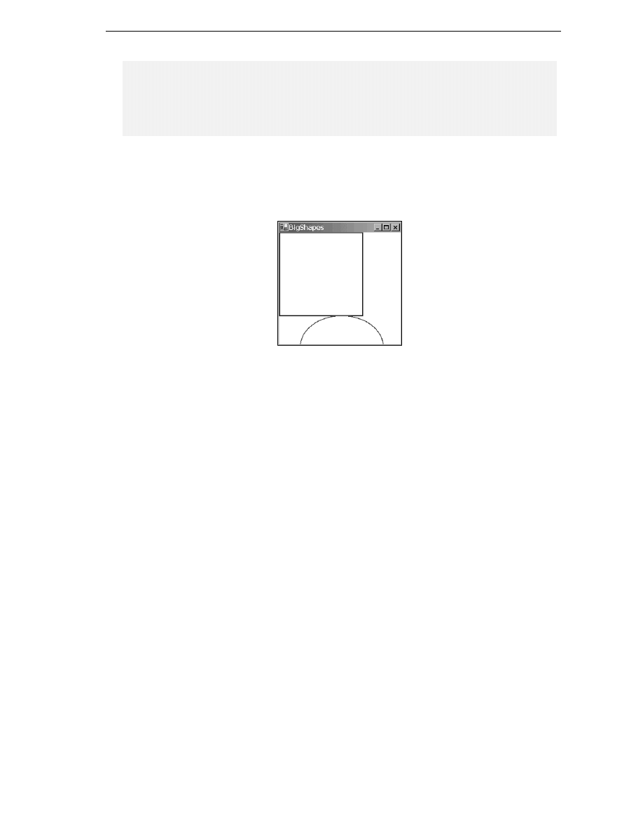
we'll start by creating a sample BigShapes, in which we will make the rectangle and ellipse a bit
bigger. Also, while we're at it we'll demonstrate how to use the Point, Size and Rectangle structs by
using them define the drawing areas. With these changes, the relevant part of the Form1 class looks like
this:
// member fields
private Point rectangleTopLeft = new Point(0, 0);
private Size rectangleSize = new Size(200,200);
private Point ellipseTopLeft = new Point(50, 200);
private Size ellipseSize = new Size(200, 150);
private Pen bluePen = new Pen(Color.Blue, 3);
private Pen redPen = new Pen(Color.Red, 2);
private void InitializeComponent()
{
this.components = new System.ComponentModel.Container();
this.Size = new System.Drawing.Size(300,300);
this.Text = "Scroll Shapes";
this.BackColor = Color.White;
}
#endregion
protected override void OnPaint( PaintEventArgs e )
{
Graphics dc = e.Graphics;
if (e.ClipRectangle.Top < 350 || e.ClipRectangle.Left < 250)
{
Graphics with GDI+
921
Rectangle RectangleArea =
new Rectangle (RectangleTopLeft, RectangleSize);
Rectangle EllipseArea =
new Rectangle (EllipseTopLeft, EllipseSize);
dc.DrawRectangle(BluePen, RectangleArea);
dc.DrawEllipse(RedPen, EllipseArea);
}
base.OnPaint(e);
}
Notice, that we've also turned the Pen objects into member fields – this is more efficient than creating a
new Pen every time we need to draw anything, as we have been doing up to now.
The result of running this sample looks like this:
We can see a problem instantly. The shapes don't fit in our 300x300 pixel drawing area.
Normally, if a document is too large to display, an application will add scroll bars to let you scroll the
window and look at a chosen part of it at a time. This is another area in which, with the kind of user
interface that we were dealing with in Chapter 9, we'd let the .NET runtime and the base classes handle
everything. If your form has various controls attached to it than the Form instance will normally know
where these controls are and it will therefore know if its window becomes so small that scroll bars
become necessary. The Form instance will also automatically add the scroll bars for you, and not only
that, but it's also able to correctly draw whichever portion of the screen you've scrolled to. In that case
there is nothing you need to explicitly do in your code. In this chapter however, we're taking
responsibility for drawing to the screen therefore, we're going to have to help the Form instance out
when it comes to scrolling.
In the last paragraph we said, if a document is too large to display. This probably made you
think in terms of something like a Word or Excel document. With drawing applications, however,
it's better to think of the document as whatever data the application is manipulating, which it needs
to draw. For our current example, the rectangle and ellipse between them constitute the document.
Getting the scrollbars added is actually very easy. The Form can still handle all that for us – the reason
it hasn't in the above ScrollShapes sample is that it doesn't know they are needed – because it
doesn't know how big an area we will want to draw in. How big an area is that? More accurately, what
we need to figure out is the size of a rectangle that stretches from the top left corner of the document (or
equivalently, the top left corner of the client area before we've done any scrolling), and which is just big
enough to contain the entire document. In this chapter, we'll refer to this area as the document area.
Looking at the diagram of the 'document' we can see that for this example the document area is (250,
350) pixels.
Chapter 21
922
200
200
200
50
150
(250, 350)
Telling the form how big the document is it is quite easy. We use the relevant property,
Form.AutoScrollMinSize
. Therefore we write this:
private void InitializeComponent()
{
this.components = new System.ComponentModel.Container();
this.Size = new System.Drawing.Size(300,300);
this.Text = "Scroll Shapes";
this.BackColor = Color.White;
this.AutoScrollMinSize = new Size(250, 350);
}
Notice, that here we've MinScrollSize in the InitializeComponent method. That's a good place
in this particular application, because we know that is how big the screen area will always be. Our
'document' never changes size while this particular application is running. Bear in mind however, that if
your application does things like display contents of files or something else for which the area of the
screen might change, that will need to set this property at other times.
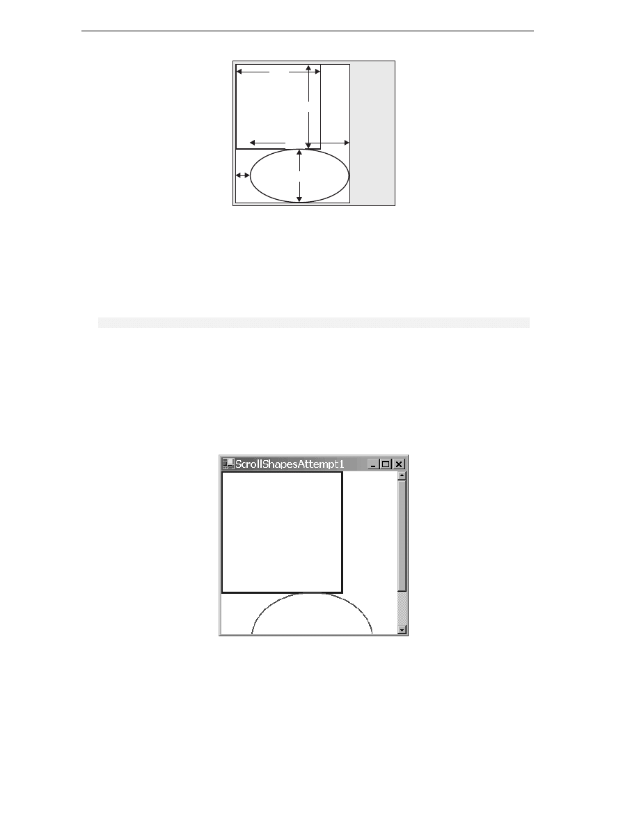
Setting MinScrollSize is a start, but it's not yet quite enough. To see, that let's look at what Scroll
Shapes looks like now. Initially we get the screen that correctly displays the shapes:
Graphics with GDI+
923
Notice, that not only has the form correctly set the scrollbars, but it's even correctly sized them to
indicate what proportion of the document is currently displayed. You can try resizing the window while
the sample is running – you'll find the scroll bars respond correctly, and even disappear if we make the
window big enough that they are no longer needed.
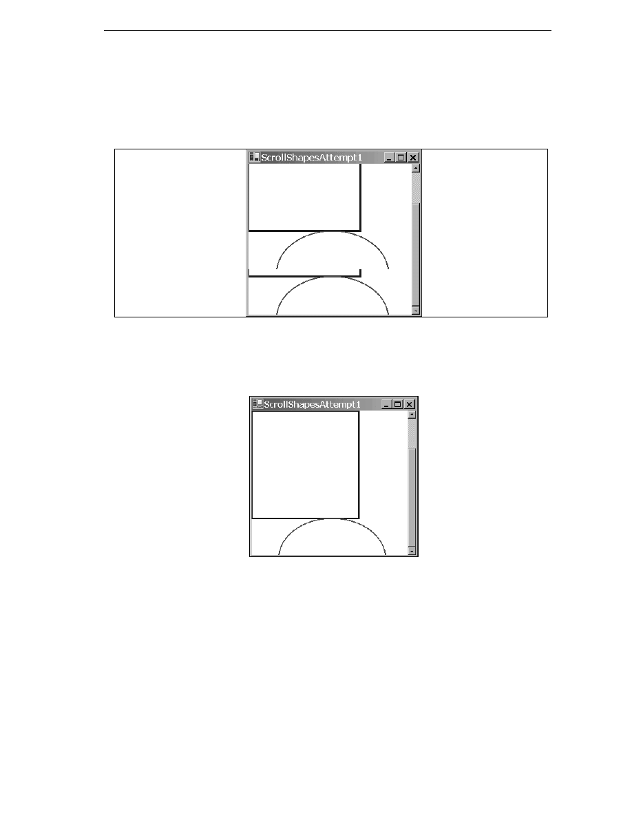
However, now look what happens however if we actually use one of the scroll bars and scroll down a
bit:
Clearly something has gone wrong!
In fact, what's gone wrong, is that we haven't taken into account the position of the scrollbars in the
code in our OnPaint() override. We can see this very clearly if we force the window to completely
repaint itself by minimizing and restoring it. The result looks like this:
The shapes have been painted, just as before, with the top left corner of the rectangle nestled into the
top left corner of the client area – just as if we hadn't moved the scroll bars at all.
Before we go over how to correct this problem, we'll take a closer look at precisely what is happening in
these screenshots. Doing so is quite instructive, both because it'll help us to understand exactly how the
drawing is done in the presence of scroll bars and because it'll be quite good practice: If you start using
GDI+, I promise you that sooner or later, you'll find yourself presented with a strange drawing like one
of the ones above, and having to try to figure out what has gone wrong.
Chapter 21
924
We'll look at the last screenshot first since that one is easy to deal with. The ScrollShapes sample has
just been restored so the entire window has just been repainted. Looking back at our code it instructs
the graphics instance to draw a rectangle with top left coordinates (0,0) – relative to the top left corner
of the client area of the window – which is what has been drawn. The problem is, that the graphics
instance by default interprets coordinates as relative to the client window – it doesn't know anything
about the scroll bars. Our code as yet does not attempt to adjust the coordinates for the scrollbar
positions. The same goes for the ellipse.
Now, we can tackle the earlier screenshot, from immediately after we'd scrolled down. We notice that
here the top two-thirds or so of the window look fine. That's because these were drawn when the
application first started up. When you scroll windows, Windows doesn't ask the application to redraw
what was already on the screen. Windows is smart enough to figure out for itself which bits of what's
currently being displayed on the screen can be smoothly moved around to match where the scrollbars
now are. That's a much more efficient process, since it may be able to use some hardware acceleration
to do that too. The bit in this screenshot that's wrong is the bottom roughly one-third of the window.
This part of the window didn't get drawn when the application first appeared since before we started
scrolling it was outside the client area. This means that Windows asks our ScrollShapes application
to draw this area. It'll raise a Paint event passing in just this area as the clipping rectangle. And that's
exactly what our OnPaint() override has done. This rather strange screenshot results from the
application having done exactly what we told it to do!
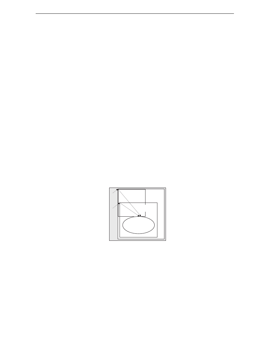
One way of looking at the problem is that we are at the moment expressing our coordinates relative to
the top left corner of the start of the 'document' – we need to convert them to express them relative to
the top left corner of the client area instead. The diagram should make this clear. In the diagram the
thin rectangles mark the borders of the screen area and of the entire document (to make the diagram
clearer we've actually extended the document further downwards and to the right, beyond the
boundaries of the screen, but this doesn't change our reasoning. We've also assumed a small horizontal
scroll as well as a vertical one). The thick lines mark the rectangle and ellipse that we are trying to draw.
P marks some arbitrary point that we are drawing, which we're going to take as an example. When
calling the drawing methods we've supplied the graphics instance with the vector from point B to (say)
point P, this vector expressed as a Point instance. We actually need to give it the vector from point A
to point P.
P
Document
Client Area
(Screen)
B
A
The problem is, that we don't know what the vector from A to P is. We know what B to P is – that's just
the coordinates of P relative to the top left corner of the document – the position where we want to draw
point P in the document. We also know what the vector from B to A is – that's just the amount we've
scrolled by; this is stored in a property of the Form class called AutoScrollPosition. However, we
don't know the vector from A to P. Now, if you were good at math at school, you might remember what
the solution to this is – you just have to subtract vectors. Say, for example, to get from B to P you move
150 pixels across and 200 pixels down, while to get from B to A you have to move 10 pixels across and
57 pixels down. That means to get from A to P you have to move 140 (=150 minus 10) pixels across and
143 (=200 minus 57) pixels down. In computer terms we just have to do this calculation.
Graphics with GDI+
925
However it's actually a bit easier than that. I've gone through the process in detail, so you know exactly
what's going on, but the Graphics class actually implements a method that will do these calculations
for us. It's called TranslateTransform. How it works is that you pass it the horizontal and vertical
coordinates that say where the top left of the client area is relative to the top left corner of the
document, (our AutoScrollPosition property, that is the vector from B to A in the diagram). Then
the Graphics device will from then on work out all its coordinates taking into account where the client
area is relative to the document.
After all that explanation, all we need to do is add this line to our drawing code:
dc.TranslateTransform(this.AutoScrollPosition.X, this.AutoScrollPosition.Y);
In fact in our sample, it's a little more complicated because we also are separately testing whether we
need to do any drawing by looking at the clipping region. We need to adjust this test to take the scroll
position into account too. When we've done that, the full drawing code for the sample (downloadable
from the Wrox Press website as the ScrollShapes) looks like this:
protected override void OnPaint( PaintEventArgs e )
{
Graphics dc = e.Graphics;
Size ScrollOffset = new Size(this.AutoScrollPosition);
if (e.ClipRectangle.Top+ScrollOffset.Width < 350 ||
e.ClipRectangle.Left+ScrollOffset.Height < 250)
{
Rectangle RectangleArea = new Rectangle
(RectangleTopLeft+ScrollOffset, RectangleSize);
Rectangle EllipseArea = new Rectangle
(EllipseTopLeft+ScrollOffset, EllipseSize);
dc.DrawRectangle(BluePen, RectangleArea);
dc.DrawEllipse(RedPen, EllipseArea);
}
base.OnPaint(e);
}
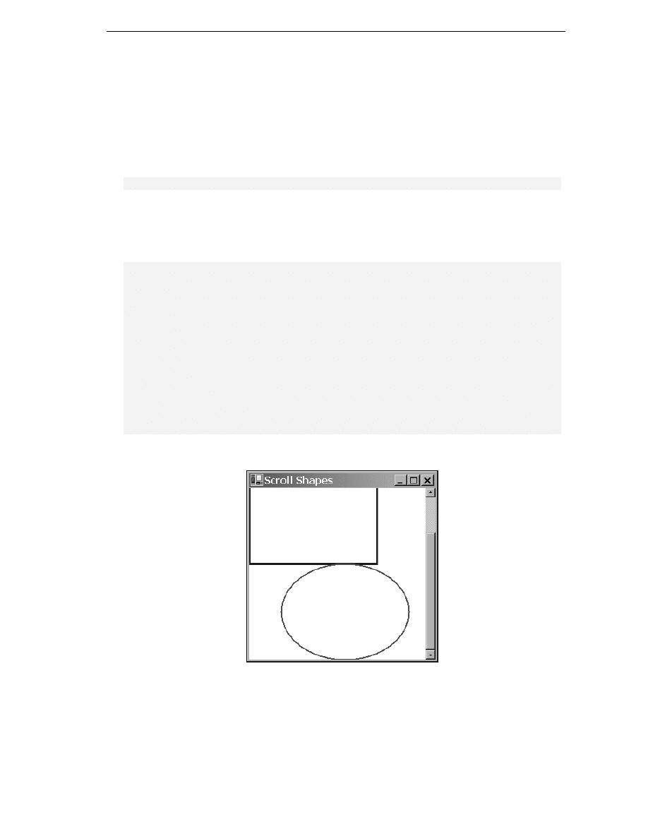
Now, we have our scroll code working perfectly, we can at last obtain a correctly scrolled screenshot!

Chapter 21
926
World, Page and Device Coordinates
The distinction between measuring position relative to the top-left corner of the document and
measuring it relative to the top-left corner of the screen, is so important that GDI+ has special names for
them:
❑
World Coordinates
are the position of a point measured in pixels from the top left corner of
the document. The name reflects the fact that the entire document can loosely be thought of as
the 'world' as far as the program is concerned.
❑
Page Coordinates
are the position of a point measured in pixels from the top left corner of the
client area. The name comes from thinking of the displayed area as a 'page' of displayed
output.
Developers familiar with GDI will note that, World Coordinates correspond to what in GDI were
known as logical coordinates. Page coordinates correspond to what used to be known as device
coordinates. Those developers should also note, that the way you code up conversion between logical
and device coordinates has changed in GDI+. In GDI, conversions took place via the device context,
using the LPtoDP() and DPtoLP() Windows API functions. In GDI+, it's the Form object that
maintains the information needed to carry out the conversion.
GDI+ also distinguishes a third coordinate, which is now known as device coordinates. Device
coordinates are similar to page coordinates, except that we do not use pixels as the unit of measurement
– instead we use some other unit that can be specified by the user by calling the Graphics.PageUnit
property. Possible units, besides the default of pixels, include inches and millimeters. Although we won't
use the PageUnit property in this chapter, it can be useful as a way of getting around the different pixel
densities of devices. For example, 100 pixels on most monitors will occupy something like an inch.
However, laser printers can have anything up to thousands of dpi (dots per inch) – which means that a
shape specified to be 100 pixels wide will look a lot smaller when printed on such a laser printer. By
setting the units to, say, inches – and specify that the shape should be 1 inch wide, you can ensure that
the shape will look the same size on the different devices.
Colors
In this section, we're going to look at the ways that you can specify what color you want something to be
drawn in.
Colors in GDI+ are represented by instances of the System.Drawing.Color struct. Generally, once
you've instantiated this struct, you won't do much with the corresponding Color instance – just pass it
to whatever other method you are calling that requires a Color. We've encountered this struct once
before – when we set the background color of the client area of the window in each of our samples. The
Form.BackColor
property actually returns a Color instance. In this section, we'll look at this struct in
more detail. In particular, we'll examine several different ways that you can construct a Color.
Red-Green-Blue (RGB) Values
The total number of colors that can be displayed by a monitor is huge – over 16 million. To be exact
the number is 2 to the power 24, which works out at 16777216. Obviously we need some way of
indexing those colors so we can indicate which of these is the color we want to display at a given pixel.

Graphics with GDI+
927
The most common way of indexing colors, is by dividing them into the red green and blue components.
This idea is based on the principle that any color that the human eye can distinguish can be constructed
from a certain amount of red light, a certain amount of the green light and a certain amount of blue
light. These lights are known as components. In practice, it's found that if we divide the amount of each
component light into 256 possible intensities that gives a sufficiently fine gradation to be able to display
images that are perceived by the human eye to be of photographic quality. We therefore, specify colors
by giving the amounts of these components on a scale of an 0 to 255 where 0 means that the
components is not present and 255 means that it is at its maximum intensity.
We can now see where are quoted figure of 16,777,216 colors comes from since that number is just 256 cubed.
This gives us our first way of telling GDI+ about a color. You can indicate a color's red, green and blue
values by calling the static function Color.FromArgb(). Microsoft has chosen not to supply a
constructor to do this task. The reason is that there are other ways, besides the usual RGB components,
to indicate a constructor. Because of this, Microsoft felt that the meaning of parameters passed to any
constructor they defined would be open to misinterpretation:
Color RedColor = Color.FromArgb (255,0,0);
Color FunnyOrangyBrownColor = Color.FromArgb(255,155,100);
Color BlackColor = Color.FromArgb(0,0,0);
Color WhiteColor = Color.FromArgb(255,255,255);
The three parameters are respectively the quantities of red, green, and blue. There are a number of
other overloads to this function, some of which also allow you to specify something called an alpha-
blend (that's the A in the name of the method, FromArgb()!) Alpha blending is beyond the scope of
this chapter, and allows you paint a color semi-transparently by combining it with whatever color was
already on the screen. This can give some beautiful effects and is often used in games.
The Named Colors
Constructing a Color using FromArgb() is the most flexible technique, since it literally means you can
specify any color that the human eye can see. However, if you want a simple, standard, well-known
color such as red or blue, it's a lot easier to just be able to name the color you want. Hence Microsoft
have also provided a large number of static properties in Color, each of which returns a named color.
It is one of these properties that we used when we set the background color of our windows to white in
our samples:
this.BackColor = Color.White;
// has the same effect as:
// this.BackColor = Color.FromArgb(255, 255 , 255);
There are several hundred such colors. The full list is given in the MSDN documentation. They include
all the simple colors: Red, White, Blue, Green, Black and so on. as well as such delights as
MediumAquamarine
, LightCoral, and DarkOrchid.
Incidentally, although it might look that way, these named colors have not been chosen at random.
Each one represents a precise set of RGB values, and they were originally chosen many years ago for
use on the Internet. The idea was to provide a useful set of colors right across the spectrum whose
names would be recognized by web browsers – thus, saving you from having to write explicit RGB
values in your HTML code. A few years ago these colors were also important because early browsers
couldn't necessarily display very many colors accurately, and the named colors were supposed to
provide a set of colors that would be displayed correctly by most browsers. These days that aspect is
less important since modern web browsers are quite capable of displaying any RGB value correctly.

Chapter 21
928
Graphics Display Modes and the Safety Palette
Although we've said that in principle monitors can display any of the over 16 million RGB colors, in
practice this depends on how you've set the display properties on your computer. You're probably
aware that by right-clicking on the backdrop in Windows and selecting
Settings
from the resultant
property sheet, you get the option to choose the display color resolution. There are traditionally three
main options here (though some machines may provide other options depending on the hardware): true
color (24-bit), high color (16-bit) and 256 colors. (On some graphics cards these days, true color is
actually marked as 32-bit for reasons to do with optimizing the hardware, though in that case only 24
bits of the 32 bits are used for the color itself).
Only true-color mode allows you to display all of the RGB colors simultaneously. This sounds the best
option, but it comes at a cost: 3 bytes are needed to hold a full RGB value which means 3 bytes of
graphics card memory are needed to hold each pixel that is displayed. If graphics card memory is at a
premium (a restriction that's less common now than it used to be) you may choose one of the other
modes. High color mode gives you two bytes per pixel. That's enough to give 5 bits for each RGB
component. So instead of 256 gradations of red intensity you just get 32 gradations; the same for blue
and green, which gives a total of 65536 colors. That is just about enough to give apparent photographic
quality on a casual inspection, though areas of subtle shading tend to be broken up a bit.
256-color mode gives you even fewer colors. However, in this mode, you get to choose which colors.
What happens is that the system sets up something known as a palette. This is a list of 256 colors
chosen from the 16 billion RGB colors. Once you've specified the colors in the palette, the graphics
device will be able to display just those colors. The palette can be changed at any time – but the
graphics device can still only display 256 different colors on the screen at any one time. 256-color mode
is only really used when high performance and video memory is at a premium. Most games will use this
mode – and they can still achieve decent looking graphics because of a very careful choice of palette.
In general, if a display device is in high color or 256-color mode and it is asked to display a particular
RGB color, it will pick the nearest mathematical match from the pool of colors that it is able to display.
It's for this reason that it's important to be aware of the color modes. If you are drawing something that
involves subtle shading or photographic quality images, and the user does not have 24-bit color mode
selected, s/he may not see the image the same way you intended it. So if you're doing that kind of work
with GDI+, you should test your application in different color modes. (It is also possible for your
application to programmatically set a given color mode, though we won't go into that in this chapter.)
The Safety Palette
For reference, we'll quickly mention the safety palette here. It is a very commonly used default palette.
The way it works is that we set six equally spaced possible values for each color component. Namely,
the values 0, 51, 102, 153, 204, 255. In other words, the red component can have any of these values. So
can the green component. So can the blue component. So possible colors from the safety palette include
(0,0,0) (black), (153,0,0) (a fairly dark shade of red), (0, 255, 102) (green with a smattering of blue
added), and so on. This gives us a total of 6 cubed = 216 colors. The idea is that this gives us an easy
way of having a palette that contains colors from right across the spectrum and of all degrees of
brightness, although in practice this doesn't actually work that well because equal mathematical spacing
of color components doesn't mean equal perception of color differences by the human eye. Because the
safety palette used to be widely used however, you'll still find a fair number of applications and images
exclusively use colors from the safety palette.
If you set Windows to 256-color mode, you'll find the default palette you get is the safety palette, with
20 Windows standard colors added to it, and 20 spare colors.

Graphics with GDI+
929
Pens and Brushes
In this section, we'll review two helper classes that are needed in order to draw shapes. We've already
encountered the Pen class, used to tell the graphics instance how to draw lines. A related class is
System.Drawing.Brush
, which tells it how to fill regions. For example, the Pen is needed to draw the
outlines of the rectangle and ellipse in our previous samples. If we'd needed to draw these shapes as
solid, it would have been a brush that would have been used to specify how to fill them in. One aspect
of both of these classes, is that you will hardly ever call any methods on them. You simply construct a
Pen
or Brush instance with the required color and other properties, and then pass it to drawing
methods that require a Pen or Brush.
We will look at brushes first, then pens.
Incidentally, if you've programmed using GDI before you have noticed from the first couple samples
that pens are used in a different way in GDI+. In GDI the normal practice was to call a Windows
API function, SelectObject(), which actually associated a pen with the device context. That
pen was then used in all drawing operations that required a pen until you informed of the device
context otherwise, by calling SelectObject()again. The same principle held for brushes and
other objects such as fonts or bitmaps. With GDI+, as mentioned earlier, Microsoft has instead gone
for a stateless model in which there is no default pen or other helper object. Rather, you simply
specify with each method call the appropriate helper object to be used for that particular method.
Brushes
GDI+ has several different kinds of brush – more than we have space to go into this chapter, so we'll
just explain the simpler ones to give you an idea of the principles. Each type of brush is represented by
an instance of a class derived from System.Drawing.Brush (this class is abstract so you can't
instantiate Brush objects themselves – only objects of derived classes). The simplest brush simply
indicates that a region is to be filled with solid color. This kind of brush is represented by an instance of
the class System.Drawing.SolidBrush, which you can construct as follows:
Brush solidBeigeBrush = new SolidBrush(Color.Beige);
Brush solidFunnyOrangyBrownBrush =
new SolidBrush(Color.FromArgb(255,155,100));
Alternatively, if the brush is one of the Internet named colors you can use construct the brush more
simply using another class, System.Drawing.Brushes. Brushes is one of those classes that you
never actually instantiate (it's got a private constructor to stop you doing that). It simply has a large
number of static properties, each of which returns a brush of a specified color. You'd use Brushes like
this:
Brush solidAzureBrush = Brushes.Azure;
Brush solidChocolateBrush = Brushes.Chocolate;
The next level of complexity is a hatch brush, which fills a region by drawing a pattern. This type of
brush is considered more advanced so it's in the Drawing2D namespace, represented by the class
System.Drawing.Drawing2D.HatchBrush
. The Brushes class can't help you with hatch brushes –
you'll need to construct one explicitly, by supplying the hatch style and two colors – the foreground
color followed by the background color (but you can omit the background color in which case it
defaults to black). The hatch style comes from an enumeration,
System.Drawing.Drawing2D.HatchStyle
. There are a large number of HatchStyle values
available, so it's easiest to refer to the MSDN documentation for the full list. To give you an idea, typical
styles include ForwardDiagonal, Cross, DiagonalCross, SmallConfetti, and ZigZag. Examples
of constructing a hatch brush include:

Chapter 21
930
Brush crossBrush = new HatchBrush(HatchStyle.Cross, Color.Azure);
// background color of CrossBrush is black
Brush brickBrush = new HatchBrush(HatchStyle.DiagonalBrick,
Color.DarkGoldenrod, Color.Cyan);
Solid and hatch brushes are the only brushes available under GDI. GDI+ has added a couple of new
styles of brush:
❑
System.Drawing.Drawing2D.LinearGradientBrush
fills in an area with a color that
varies across the screen.
❑
System.Drawing.Drawing2D.PathGradientBrush
is similar, but in this case the color
varies along a path around the region to be filled.
We won't go into these brushes in this chapter. We'll note though that both can give some spectacular
effects if used carefully. The Bezier sample in Chapter 9 uses a linear gradient brush to paint the
background of the window.
Pens
Unlike brushes, pens are represented by just one class – System.Drawing.Pen. The pen is however,
actually slightly more complex than the brush, because it needs to indicate how thick lines should be
(how many pixels wide) and, for a wide line, how to fill the area inside the line. Pens can also specify a
number of other properties which are beyond the scope of this chapter, but which include the
Alignment
property that we mentioned earlier, which indicates where in relation to the border of a
shape a line should be drawn, as well as what shape to draw at the end of a line (whether to round off
the shape).
The area inside a thick line can be filled with solid color, or it can be filled using a brush. Hence, a Pen
instance may contain a reference to a Brush instance. This is quite powerful though, as it means you
can draw lines colored using hatching or linear shading. There are four different ways that you can
construct a Pen instances that you have designed yourself. You can do it by passing a color, or you can
do it by passing in a brush. Both of these constructors will produce a pen with a width of one pixel.
Alternatively, you can pass in a color or a brush, and additionally a float which represents the width
of the pen. (It needs to be a float in case we are using non-default units such as millimeters or inches for
the Graphics object that will do the drawing – so we can for example specify fractions of an inch.) So
for example, you can construct pens like this:
Brush brickBrush = new HatchBrush(HatchStyle.DiagonalBrick,
Color.DarkGoldenrod, Color.Cyan);
Pen solidBluePen = new Pen(Color.FromArgb(0,0,255));
Pen solidWideBluePen = new Pen(Color.Blue, 4);
Pen brickPen = new Pen(BrickBrush);
Pen brickWidePen = new Pen(BrickBrush, 10);
Additionally, for the quick construction of pens, you can use the class System.Drawing.Pens which,
like the Brushes class simply contains a number of stock pens. These pens all have width one pixel and
come in the usual sets of Internet named colors. This allows you to construct pens in this way:
Pen SolidYellowPen = Pens.Yellow;
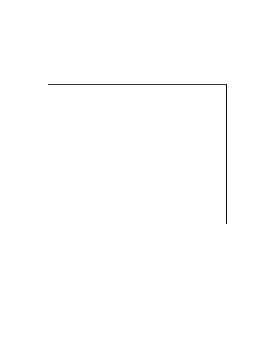
Graphics with GDI+
931
Drawing Shapes and Lines
We've almost finished the first part of the chapter, in which we've covered all the basic classes and
objects required in order to draw specified shapes and so on. to the screen. We'll round off by reviewing
some of the drawing methods the Graphics class makes available, and presenting a short sample that
illustrates several brushes and pens.
System.Drawing.Graphics
has a large number of methods that allow you to draw various lines,
outline shapes and solid shapes. Once again there are too many to provide a comprehensive list here,
but the following table gives the main ones and should give you some idea of the variety of shapes you
can draw.
Method
Typical parameters
What it draws
DrawLine
Pen, start and end points
A single straight line
DrawRectangle
Pen, position and size
Outline of a rectangle
DrawEllipse
Pen, position and size
Outline of an ellipse
FillRectangle
Brush, position and size
Solid rectangle
FillEllipse
Brush, position and size
Solid ellipse
DrawLines
Pen, array of Points
Series of lines, connecting each point to the
next one in the array
DrawBezier
Pen, 4 points
A smooth curve through the two end
points, with the remaining two points used
to control the shape of the curve
DrawCurve
Pen, array of points
A smooth curve through the points
DrawArc
Pen, rectangle, two angles
Portion of circle within the rectangle
defined by the angles
DrawClosedCurve
Pen, array of points
Like DrawCurve but also draws a straight
line to close the curve
DrawPie
Pen, rectangle, two angles
Wedge shaped outline within the rectangle
FillPie
Brush, rectangle, two angles
Solid wedge shaped area within the
rectangle
DrawPolygon
Pen, array of points
Like DrawLines but also connects first
and last points to close the figure drawn.
Before we leave the subject of drawing simple objects, we'll round off with a simple sample that
demonstrates the kinds of visual effect you can achieve by use of brushes. The sample is called
ScrollMoreShapes
, and it's essentially a revision of ScrollShapes. Besides the rectangle and
ellipse, we'll add a thick line and fill the shapes in with various custom brushes. We've already
explained the principles of drawing so we'll present the code without too many comments. First,
because of our new brushes, we need to indicate we are using the System.Drawing.Drawing2D
namespace:

Chapter 21
932
using System;
using System.Drawing;
using System.Drawing.Drawing2D;
using System.Collections;
using System.ComponentModel;
using System.Windows.Forms;
using System.Data;
Next some extra fields in our Form1 class which contain details of the locations where the shapes are to
be drawn, as well as various pens and brushes we will use:
private Rectangle rectangleBounds = new Rectangle(new Point(0,0),
new Size(200,200));
private Rectangle ellipseBounds = new Rectangle(new Point(50,200),
new Size(200,150));
private Pen BluePen = new Pen(Color.Blue, 3);
private Pen RedPen = new Pen(Color.Red, 2);
private Brush SolidAzureBrush = Brushes.Azure;
private Brush CrossBrush = new HatchBrush(HatchStyle.Cross, Color.Azure);
static private Brush BrickBrush = new HatchBrush(HatchStyle.DiagonalBrick,
Color.DarkGoldenrod,
Color.Cyan);
private Pen BrickWidePen = new Pen(BrickBrush, 10);
The BrickBrush field has been declared as static, so that we can use its value in the initializor for
BrickWidePen
that follows. C# won't let us use one instance field to initialize another instance field,
because it's not defined which one will be initialized first, but declaring the field as static solves the
problem, since only one instance of the Form1 class will be instantiated, it is immaterial whether the
fields are static or instance fields.
Here is the OnPaint() override:
protected override void OnPaint( PaintEventArgs e )
{
Graphics dc = e.Graphics;
Point scrollOffset = this.AutoScrollPosition;
dc.TranslateTransform(scrollOffset.X, scrollOffset.Y);
if (e.ClipRectangle.Top+scrollOffset.X < 350 ||
e.ClipRectangle.Left+scrollOffset.Y < 250)
{
dc.DrawRectangle(BluePen, rectangleBounds);
dc.FillRectangle(CrossBrush, rectangleBounds);
dc.DrawEllipse(RedPen, ellipseBounds);
dc.FillEllipse(SolidAzureBrush, ellipseBounds);
dc.DrawLine(BrickWidePen, rectangleBounds.Location,
ellipseBounds.Location+ellipseBounds.Size);
}
base.OnPaint(e);
}
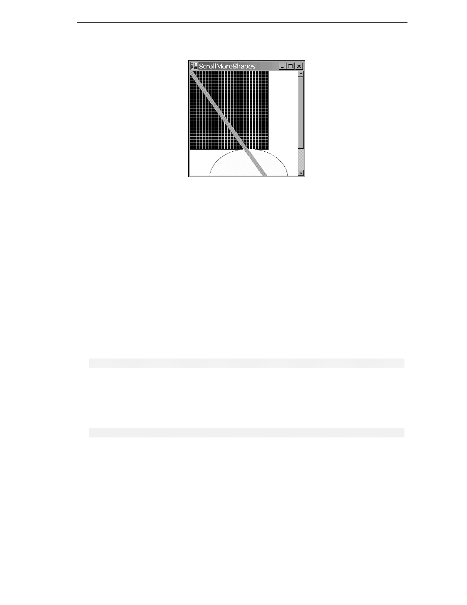
Graphics with GDI+
933
Now the results:
Notice that the thick diagonal line has been drawn on top of the rectangle and ellipse, because it was the
last item to be painted.
Displaying Images
One of the most common things you may want to do with GDI+ is display an image that already exists
in a file. This is actually a lot simpler than drawing your own user interface, because the image is
already pre-drawn. Effectively, all you have to do is load the file and instruct GDI+ to display it. The
image can be a simple line drawing, an icon, or a complex image such as a photograph. It's also possible
to perform some manipulations on the image, such as stretching it or rotating it, and you can choose to
display only a portion of it.
In this section, we'll reverse the usual order of things in this chapter: We'll present the sample, then
we'll discuss some of the issues you need to be aware of when displaying images. We can do this,
because the code needed to display an image really is so simple.
The class we need is the .NET base class, System.Drawing.Image. An instance of Image represents
one image – if you like, one picture. Reading in an image takes one line of code:
Image MyImage = Image.FromFile("FileName");
FromFile()
is a static member of Image and is the usual way of instantiating an image. The file can be
any of the commonly supported graphics file formats, including .bmp, .jpg, .gif, and .png.
Displaying an image also takes just one line of code, assuming you have a suitable Graphics instance
to hand:
dc.DrawImageUnscaled(MyImage, TopLeft);
In this line of code, dc is assumed to be a Graphics instance, MyImage is the Image to be displayed,
and TopLeft is a Point struct that stores the device coordinates of where you want the image to be
placed.

Chapter 21
934
It could hardly be easier could it!
Images are probably the area in which developers familiar with GDI will notice the biggest
difference with GDI+. In GDI, the API for dealing with images was arcane to say the least.
Displaying an image involved several nontrivial steps. If the image was a bitmap, loading it was
reasonably simple, but if it were any other file type loading it would involve a sequence of calls to
OLE objects. Actually, getting a loaded image onto the screen involved getting a handle to it,
selecting it into a memory device context then performing a block transfer between device contexts.
Although the device contexts and handles are still there behind the scenes, and will be needed if you
want to start doing sophisticated editing of the images from your code, simple tasks have now been
extremely well wrapped up in the GDI+ object model.
We'll illustrate the process of displaying an image with a sample called DisplayImage. The sample
simply displays a .jpg file in the application's main window. To keep things simple, the path of the
.jpg
file is hard coded into the application (so if you run the sample you'll need to change it to reflect
the location of the file in your system). The .jpg file we'll display is a group photograph of attendees
from a recent COMFest event.
As usual for this chapter, the DisplayImage project is a standard C# Visual Studio.NET generated
windows application. We add the following field to our Form1 class:
Image Piccy;
We then load the file in our InitializeComponent routine
private void InitializeComponent()
{
this.components = new System.ComponentModel.Container();
this.Size = new System.Drawing.Size(600, 400);
this.Text = "Display COMFest Image";
this.BackColor = Color.White;
Piccy =
Image.FromFile(@"c:\ProCSharp\Chapter21\DisplayImage\CF4Group.jpg");
this.AutoScrollMinSize = Piccy.Size;
}
Note that the size in pixels of the image is obtained as its Size property, which we use to set the
document area. The image is displayed in the OnPaint() override:
protected override void OnPaint(PaintEventArgs e)
{
Graphics dc = e.Graphics;
dc.DrawImageUnscaled(Piccy, this.AutoScrollPosition);
base.OnPaint(e);
}
The choice of this.AutoScrollPosition as the device coordinate ensures that the window will
scroll correctly, with the image located starting at the top left corner of the client area before any
scrolling has taken place.
Finally, we'll take particular note of the modification made to the code wizard generated
Form1.Dispose()
method:
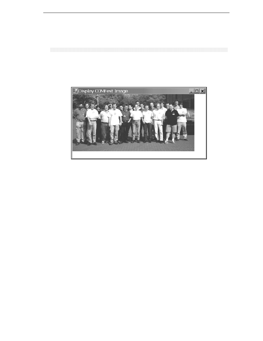
Graphics with GDI+
935
public override void Dispose()
{
base.Dispose();
if(components != null)
components.Dispose();
Piccy.Dispose();
}
Disposing of the image when it's no longer needed is important, because images generally eat a lot of
memory while in use. After Image.Dispose() has been called the Image instance no longer refers to
any actual image, and so can no longer be displayed (unless you load a new image).
Running this code produces these results:
By the way if you're wondering, COMFest (
www.comfest.co.uk
) is an informal group of
developers in the United Kingdom who meet to discuss latest technologies, and swap ideas etc. The
picture includes all the attendees at COMFest 4 with the exception of the author of this chapter who
was (conveniently) taking the picture!
Issues When Manipulating Images
Although displaying images is very simple, it still pays to have some understanding of the underlying technology.
The most important point to understand about images is that they are always rectangular. That's not just
a convenience for people, it's because of the underlying technology. It's because all modern graphics
cards have hardware built in that can very efficiently copy blocks of pixels from one bit of memory to
another bit of memory. Provided that the block of pixels represents a rectangular area. This hardware
accelerated operation can occur virtually as one single operation, and as such is extremely fast. Indeed,
it is the key to modern high performance graphics. This operation is known as a bitmap block
transfer (or BitBlt – usually pronounced something like 'BITblert' or 'BITblot').
Image.DrawImageUnscaled()
internally uses a BitBlt, which is why you can see a huge image,
perhaps containing as many as a million pixels (the photo in our example has 104975 pixels) appearing,
apparently, instantly. If the computer had to manually copy the image to the screen pixel by pixel,
you'd see the image gradually being drawn over a period of up to several seconds.

Chapter 21
936
BitBlt
s are so efficient, therefore almost all drawing and manipulation of images is carried out using
them. Even some editing of images will be done by BitBlting portions of images between device
contexts that represent areas of memory. In the days of GDI, the Windows 32 API function BitBlt()
was arguably the most important and widely used function for image manipulation, though with GDI+
the BitBlt operations are largely hidden by the GDI+ object model.
It's not possible to BitBlt areas of images that are not rectangular, however similar effects can be
easily simulated. One way is to mark a certain color as transparent for the purposes of a BitBlt, so
that areas of that color in the source image will not overwrite the existing color of the corresponding
pixel in the destination device. It is also possible to specify that in the process of a BitBlt, each pixel
of the resultant image will be formed by some logical operation (such as a bitwise AND) on the colors of
that pixel, in the source image, and in the destination device before the BitBlt. Such operations are
supported by hardware acceleration, and can be used to give a variety of subtle effects. We're not going
to go into details of this here. We'll remark however, that the Graphics object implements another
method, DrawImage(). This is similar to DrawImageUnscaled(), but comes in a large number of
overloads which allow you to specify more complex forms of BitBlt to be used in the drawing process.
DrawImage()
also allows you to draw (BitBlt) only a specified part of the image, or to perform
certain other operations on it such as scaling it (expanding or reducing it in size) as it is drawn.
Drawing Text
We've left the very important topic of displaying text till later in the chapter because drawing text to the
screen is in general more complex than drawing simple graphics. Actually I ought to qualify that
statement. Just displaying a line of two of text when you're not that bothered about the appearance is
extremely easy – it takes one single call to one method of the Graphics instance,
Graphics.DrawString()
. However if you are trying to display a document that has a fair amount of
text in it, you rapidly find that things become a lot more complex. This is for two reasons:
❑
First, if you're concerned about getting the appearance just right, you need to understand
fonts. Where shape drawing requires brushes and pens as helper objects, the process of
drawing text correspondingly requires fonts as helper objects. And understanding fonts is not
trivial task. We'll provide a brief introduction to the subject in the next section, but the details
of fonts are more complex than of brushes and pens.
❑
Second, text needs to be very carefully laid out in the window. Users generally expect words
to naturally follow one another – to be lined up with clear spaces in between. Doing that is
harder than you'd think. For a start, unlike the case for shapes, you don't usually know in
advance how much space on the screen a word is going to take up. That has to be calculated
(don't worry, you don't have to do that manually – there's a method,
Graphics.MeasureString()
that will do it). Also, how much space on the screen a word
occupies will affect whereabouts on the screen every subsequent word in the document gets
placed. If your application does line wrapping then it'll need to carefully assess word sizes
before deciding where to place the break. The next time you run Word for Windows, look
carefully at the way Word is continually repositioning text as you type, changing fonts,
cutting, and pasting, etc. There's a lot of processing going on there, involving some very
carefully designed algorithms. Of course, the chances are that any GDI+ application you work
on won't be anything like as complex as Word, but if you need to display any text then many
of the same considerations still apply. That's why the final part of this chapter is devoted to a
sample that allows some simple text manipulation. To give you some idea of the problems that
kind of application brings up and the typical solutions you'll probably need to implement.
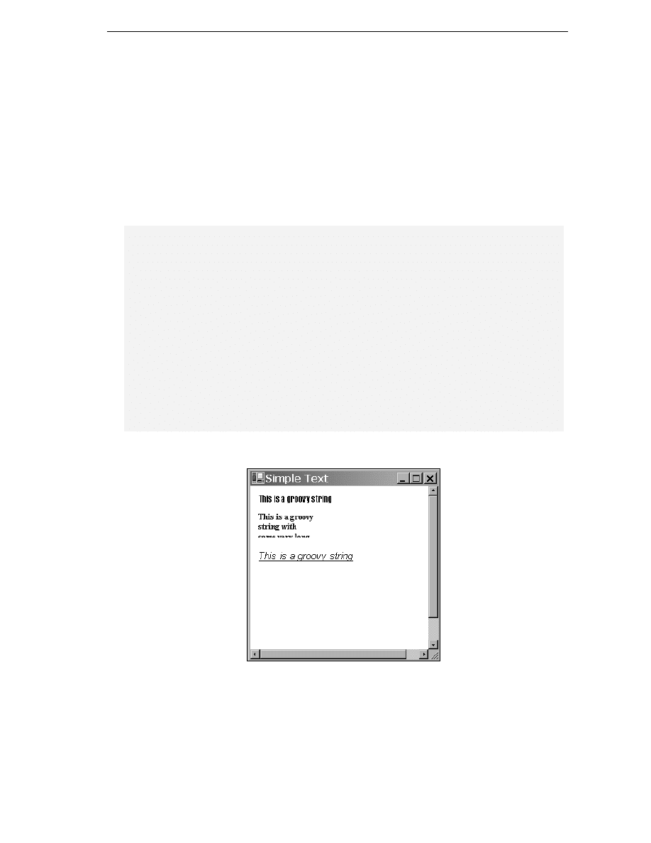
Graphics with GDI+
937
Having said all that, I don't want to scare you off too much. Good quality text processing is not
impossible – it just tricky to get right. As we've mentioned, the actual process of putting a line of
text on the screen, assuming you know the font and where you want it to go is very simple.
Therefore, the next thing we'll do is present a quick sample that shows how to display a couple of
pieces of text. After that, the plan for the rest of the chapter is to review some of the principles of
Fonts and Font Families before moving on to our more realistic text processing sample, the
CapsEditor
sample, which will demonstrate some of the issues involved when you're trying to
layouts text on-screen and also showed how to handle user input.
Simple Text Sample
The sample is our usual Windows Forms effort. This time we've overridden OnPaint() as follows:
protected override void OnPaint(PaintEventArgs e)
{
Graphics dc = e.Graphics;
Brush blackBrush = Brushes.Black;
Brush blueBrush = Brushes.Blue;
Font haettenschweilerFont = new Font("Haettenschweiler", 12);
Font boldTimesFont = new Font("Times New Roman", 10, FontStyle.Bold);
Font italicCourierFont = new Font("Courier", 11, FontStyle.Italic |
FontStyle.Underline);
dc.DrawString("This is a groovy string", haettenschweilerFont, blackBrush,
10, 10);
dc.DrawString("This is a groovy string " +
"with some very long text that will never fit in the box",
boldTimesFont, blueBrush,
new Rectangle(new Point(10, 40), new Size(100, 40)));
dc.DrawString("This is a groovy string", italicCourierFont, blackBrush,
new Point(10, 100));
base.OnPaint(e);
}
Running this sample produces this:

Chapter 21
938
The sample demonstrates the use of the Graphics.DrawString() method to draw items of text.
DrawString()
comes in a number of overloads of which we demonstrate three. The different
overloads all however, require parameters that indicate the text to be displayed, the font that the string
should be drawn in, and the brush that should be used to construct the various lines and curves that
make up each character of text. There are a couple of alternatives for the remaining parameters. In
general however, it is possible to specify either a Point (or equivalently, two numbers), or a
Rectangle
. If you specify a Point, the text will start with its top left corner at that Point and simply
stretch out to the right. If you specify a Rectangle, then the Graphics instance will lay the string out
inside that rectangle. If the text doesn't fit in to bounds of the rectangle, then it'll be cut off, as you see
from the screenshot. Passing a rectangle to DrawString() means that the drawing process will take
longer, as DrawString() will need to figure out where to put line breaks, but the result may look nicer
(if the string fits in the rectangle!)
This sample also shows a couple of ways of constructing fonts. You always need the name of the font, and its size
(height). You can also optionally pass in various styles that modify how the text is to be drawn (bold, underline and
so on.)
Fonts and Font Families
We all think intuitively that we have a fairly good understanding of fonts. After all we look at them
almost all the time. A font describes exactly how each letter should be displayed, and selection of the
appropriate font as well as providing a reasonable variety of fonts within a document is an important
factor in improving readability of that document. You just have to look at the pages of this book to see
how many fonts have been used to present you with the information. In general, you will need to
choose your fonts carefully – because a poor choice of font can badly damage both the attractiveness
and the usability of your applications.
Oddly, our intuitive understanding usually isn't quite correct. Most people, if asked to name a font, will
say things like 'Arial' or 'Times New Roman' or 'Courier'. In fact, these are not fonts at all – they are
font families. The font would be something like, say, Arial 9-point italic. Get the idea? The font family
tells you in generic terms the visual style of the text. The font family is a key factor in the overall
appearance of your application, and most of us will have become used to recognizing the styles of the
most common font families, even if we're not consciously aware of this. In casual speech, font families
are often mistakenly described simply as fonts. More correctly, a font adds more information by
specifying the size of the text and also whether any of certain modifications have been applied to the
text. For example, whether it is bold, italic, underlined, or displayed in
SMALL CAPS
or as a
subscript
. Such
modifications are technically referred to as styles, though in some ways the term is misleading, since as
we've just noted the visual appearance is determined as much by the font family.
The way the size of the text is measured is by specifying its height. The height is measured in points – a
traditional unit, which represents 1/72 of an inch (or for people living outside the UK and the USA, a
point is 0.351 mm). So for example, letters in a 10-point font are 10/72 of an inch, (or roughly 1/7'' or
3.5 mm) high. You might think from that at that means you'd get seven lines of text that has a font size
10 into one inch of vertical screen or paper space. In fact, you get slightly less than this, because you
need to allow for the spacing between the lines as well.
Strictly speaking, measuring the height isn't quite as simple as that, since there are several different
heights that you need to consider. For example, there is the height of tall letters like the A or f (this
is the measurement that we really mean when we talk about the height), the additional height
occupied by any accents on letters like Å or Ñ (the internal leading), and the extra height below
the base line needed for the tails of letters like y and g (the descent). However, for this chapter we
won't worry about that. Once you specify the font family and the main height, these subsidiary
heights are determined automatically – you can't independently choose their values.

Graphics with GDI+
939
Incidentally, when you're dealing with fonts you may also encountered some other terms that are
commonly used to describe certain font families.
❑
A serif font family is one that has little tick marks at the ends of many of the lines that make up
the characters (These ticks are known as serifs). Times New Roman is a classic example of this.
❑
Sans serif font families, by contrast, don't have these ticks. Good examples of sans serif fonts
are
Arial
, and
Verdana. The lack of tick marks often gives text a blunt, in-your-face
appearance, so sans serif fonts are often used for important text.
❑
A true type font family is one which is defined by expressing the shapes of the curves that
make up the characters in a precise mathematical manner. This means that that the same
definition can be used to calculate how to draw fonts of any size within the family. These days,
virtually all the fonts you will use are true type fonts. Some older font families from the days
of Windows 3.1 were defined by individually specifying the bitmap for each character
separately for each font size, but the use of these fonts is now discouraged. (Amongst other
disadvantages they cause problems when you swap from the screen to a modern printer,
where the number of pixels per inch is far greater, so the bitmaps end up looking too small).
Microsoft has provided two main classes that we need to deal with when the selecting or manipulating
fonts. These are System.Drawing.Font and System.Drawing.FontFamily. We have already seen
the main use of the Font class. When we wish to draw text we instantiate an instance of Font and pass
it to the DrawString method to indicate how the text should be drawn. A FontFamily instance is
used (surprisingly enough) to represent a family of fonts.
One use of the FontFamily class is if you know you want a font of a particular type (Serif, SansSerif or
Monospace), but don't mind which font. The static properties GenericSerif, GenericSansSerif,
and GenericMonospace return default fonts that satisfy these criteria:
FontFamily sansSerifFont = FontFamily.GenericSansSerif;
Generally speaking, however, if you're writing a professional application, you will want to choose your
font in a more sophisticated way than this. Most likely, you will implement your drawing code, so that it
checks what font families are actually installed on the computer and hence what fonts are available.
Then it will select the appropriate one. Perhaps by taking the first available one on a list of preferred
fonts. And if you want your application to be very user friendly, the first choice on the list will probably
be the one that the user selected last time they ran your software. Usually, if you're dealing with the
most popular fonts families, such as Arial and Times New Roman, you'll be safe. However, if you do try
to display text using a font that doesn't exist the results aren't always predictable and you're quite likely
to find the Windows just substitutes the standard system font, which is very easy for the system to draw
but it doesn't look very pleasant and if it does appear in your document it's likely to give the impression
of very poor quality software.
You can find out what fonts are available on your system using a class called
InstalledFontCollection
, which is in the System.Drawing.Text namespace. This class
represents implements a property, Families, which is an array of all the fonts that are available to use
on your system:
InstalledFontCollection insFont = new InstalledFontCollection();
FontFamily [] families = insFont.Families;
foreach (FontFamily family in families)
{
// do processing with this font family
}
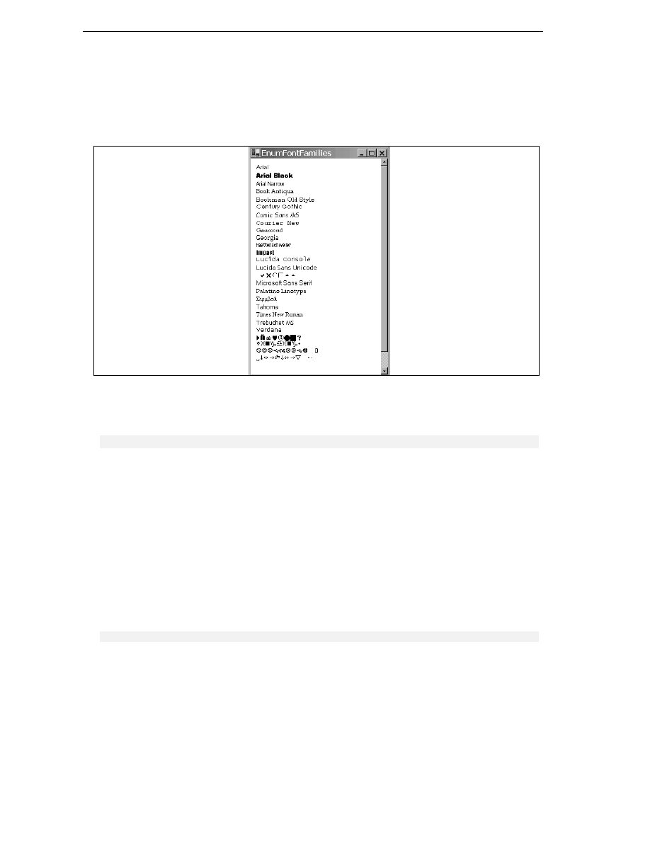
Chapter 21
940
Example: Enumerating Font Families
In this section, we will work through a quick sample, EnumFontFamilies, which lists all the font
families available on the system and illustrates them by displaying the name of each family using an
appropriate font (the 10-point regular version of that font family). When the sample is run it
looks like this:
Note, however that, depending on what fonts you have installed on your computer, you may get
different results when you run it. For this sample we have as usual created a standard C# windows
application named EnumFontFamilies. We then add the following constant to the Form1 class:
const int margin = 10;
The margin is the size of the left and top margin between the text and the edge of the document – it
stops the text from appearing right at the edge of the client area.
This is designed as a quick-and-easy way of showing off font families therefore, the code is crude and in
many cases doesn't do things the way you really ought to in a real application. For example, I've just
hard coded in a guessed value for the document size instead of calculating how much space we actually
need to display the list of font families. (We'll use a more correct approach in the next sample). Hence,
our InitializeComponent() method looks like this.
private void InitializeComponent()
{
this.components = new System.ComponentModel.Container();
this.Size = new System.Drawing.Size(300,300);
this.Text = "EnumFontFamilies";
this.BackColor = Color.White;
this.AutoScrollMinSize = new Size(200,500);
}

Graphics with GDI+
941
And here is the OnPaint() method:
protected override void OnPaint(PaintEventArgs e)
{
int verticalCoordinate = margin;
Point topLeftCorner;
InstalledFontCollection insFont = new InstalledFontCollection();
FontFamily [] families = insFont.Families;
e.Graphics.TranslateTransform(AutoScrollPosition.X,
AutoScrollPosition.Y);
foreach (FontFamily family in families)
{
if (family.IsStyleAvailable(FontStyle.Regular))
{
Font f = new Font(family.Name, 10);
topLeftCorner = new Point(margin, verticalCoordinate);
verticalCoordinate += f.Height;
e.Graphics.DrawString (family.Name, f,
Brushes.Black,topLeftCorner);
f.Dispose();
}
}
base.OnPaint(e);
}
In this code we start off by using an InstalledFontCollection object to obtain an array that
contains details of all the available font families. For each family, we instantiate a font of that family of
size 10 point. We use a simple constructor for Font – there are many more that allow more options to
be specified. The constructor we've picked takes two parameters: the name of the family and the
size of the font:
Font f = new Font(family.Name, 10);
This constructor constructs a font that has the regular style (that is, it is not underlined, italic or struck-
through). To be on the safe side however, we first check that this style is available for each font family
before attempting to display anything using that font. This is done using the
FontFamily.IsStyleAvailable()
method, and this check is important, because not all fonts are
available in all styles:
if (family.IsStyleAvailable(FontStyle.Regular))
FontFamily.IsStyleAvailable()
takes one parameter, a FontStyle enumeration. This
enumeration contains number of flags that may be combined with the bitwise OR operator. The possible
flags are Bold, Italic, Regular, Strikeout and Underline.
Finally, we note that we use a property of the Font class, Height, which returns the height needed to
display text of that font, in order to work out the line spacing,
Font f = new Font(family.Name, 10);
topLeftCorner = new Point(margin, verticalCoordinate);
verticalCoordinate += f.Height;
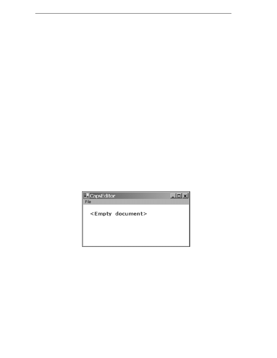
Chapter 21
942
Again to keep things simple, our version of OnPaint()reveals some bad programming practices. For a
start, we haven't bothered to check what area of the document actually needs drawing – we just try to
display everything. Also, instantiating a Font is, as remarked earlier, a computationally intensive
process, so we really ought to save the fonts rather than instantiating new copies every time OnPaint()
is called. As a result of the way the code has been designed, you may notice that this sample actually
takes a noticeable time to paint itself. In order to try to conserve memory and help the garbage
collector out we do however, call Dispose() on each font instance after we have finished with it. If we
didn't, then after 10 or 20 paint operations, there'd be a lot of wasted memory storing fonts that
are no longer needed.
Editing a Text Document: The CapsEditor Sample
We now come to our larger sample of the chapter. The CapsEditor sample is designed to illustrate
how the principles of drawing that we've learned up till now need to be applied in a more realistic
example. The sample won't require any new material, apart from responding to user input via the
mouse, but it will show how to manage the drawing of text so the application maintains performance
while ensuring that the contents of the client area of the main window are always kept up to date.
The CapsEditor program is functionally quite simple. It allows the user to read in a text file, which is
then displayed line by line in the client area. If the user double-clicks on any line, that line will be
changed to all uppercase. That's literally all the sample does. Even with this limited set of features, we'll
find that the work involved in making sure everything gets displayed in the right place while
considering performance issues (such as only displaying what we need to in a given OnPaint() call) is
quite complex. In particular, we have a new element here, that the contents of the document can change
– either when the user selects the menu option to read a new file or when s/he double clicks to
capitalize a line. In the first case we need to update the document size, so the scroll bars still work
correctly, and redisplay everything. In the second case, we need to check carefully whether the
document size is changed, and what text needs to be redisplayed.
We'll start by reviewing the appearance of CapsEditor. When the application is first run, it has no
document loaded, and displays this:
The
File
menu has two options:
Open
, and
Exit
.
Exit
exits the application, while
Open
brings up the
standard
OpenFileDialog
and reads in whatever file the user selects. This screenshot shows
CapsEditor
being used to view its own source file, Form1.cs. I've also randomly double-clicked on a
couple of lines to convert them to uppercase:
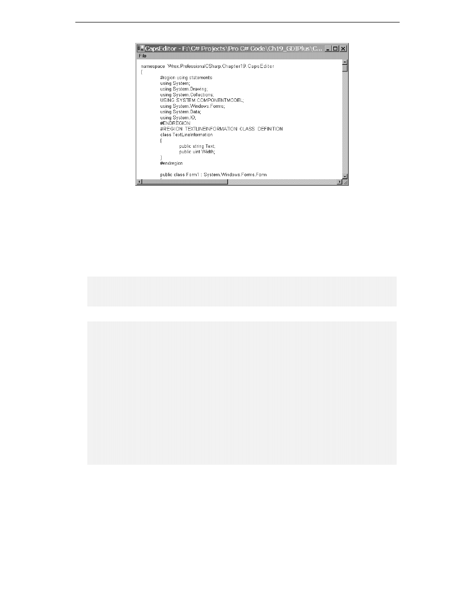
Graphics with GDI+
943
The sizes of the horizontal and vertical scrollbars are by the way correct. The client area will scroll just
enough to view the entire document. (It's a long program, and there are a couple of extremely long
code-wizard-generated lines in it, hence the shortness of both scrollbars). CapsEditor doesn't try to
wrap lines of text – the sample is already complicated enough without doing that. It just displays each
line of the file exactly as it is read in.There are no limits to the size of the file, but we are assuming it is a
text file and doesn't contain any non-printable characters.
We'll start off by adding in some fields to the Form1 class that we'll need:
#region constant fields
private const string standardTitle = "CapsEditor";
// default text in titlebar
private const uint margin = 10;
// horizontal and vertical margin in client area
#endregion
#region Member fields
private ArrayList documentLines = new ArrayList();
// the 'document'
private uint lineHeight;
// height in pixels of one line
private Size documentSize;
// how big a client area is needed to
// display document
private uint nLines;
// number of lines in document
private Font mainFont;
// font used to display all lines
private Font emptyDocumentFont; // font used to display empty message
private Brush mainBrush = Brushes.Blue;
// brush used to display document text
private Brush emptyDocumentBrush = Brushes.Red;
// brush used to display empty document message
private Point mouseDoubleClickPosition;
// location mouse is pointing to when double-clicked
private OpenFileDialog fileOpenDialog = new OpenFileDialog();
// standard open file dialog
private bool documentHasData = false;
// set to true if document has some data in it
#endregion

Chapter 21
944
Most of these fields should be self-explanatory. The documentLines field is an ArrayList which
contains the actual text of the file that has been read in. In a real sense, this is the field that contains the
data in the 'document'. Each element of DocumentLines contains information for one line of text that
has been read in. It's an ArrayList, rather than a plain C# array, so that we can dynamically add
elements to it as we read in a file. You'll notice I've also liberally used #region preprocessor directives
to block up bits of the program to make it easier to edit.
I said each documentLines element contains information about a line of text. This information is
actually an instance of another class I've defined, TextLineInformation:
class TextLineInformation
{
public string Text;
public uint Width;
}
TextLineInformation
looks like a classic case where you'd normally use a struct rather than a class
since it's just there to group together a couple of fields. However its instances are always accessed as
elements of an ArrayList, which expects its elements to be stored as reference types, so declaring
TextLineInformation
as a class makes things more efficient by saving a lot of boxing and unboxing
operations.
Each TextLineInformation instance stores a line of text – and that can be thought of as the smallest
item that is displayed as a single item. In general, for each such item in a GDI+ application, you'd
probably want to store the text of the item, as well as the world coordinates of where it should be
displayed and its size. Note world coordinates, not page coordinates. The page coordinates will change
frequently, whenever the user scrolls, whereas world coordinates will normally only change when other
parts of the document are modified in some way. In this case we've only stored the Width of the item.
The reason is because the height in this case is just the height of whatever our selected font is. It's the
same for all lines of text so there's no point storing it separately for each one. It's instead stored once, in
the Form1.lineHeight field. As for the position – well in this case the x-coordinate is just equal to the
margin, and the y-coordinate is easily calculated as:
Margin + LineHeight*(however many lines are above this one)
If we'd been trying to display and manipulate, say, individual words instead of complete lines, then the
x-position of each word would have to be calculated using the widths of all the previous words on that
line of text, but I wanted to keep it simple here, which is why we're treating each line of text
as one single item.
Let's deal with the main menu now. This part of the application is more the realm of Windows forms –
the subject of Chapter 9, than of GDI+. I added the menu options using the design view in Visual
Studio.NET, but renamed them as menuFile, menuFileOpen, and menuFileExit. I then modified
the code in InitializeComponent() to add the appropriate event handlers, as well as perform some
other initialization:
private void InitializeComponent()
{
// stuff added by code wizard
this.menuFileOpen = new System.Windows.Forms.MenuItem();
this.menuFileExit = new System.Windows.Forms.MenuItem();
this.mainMenu1 = new System.Windows.Forms.MainMenu();

Graphics with GDI+
945
this.menuFile = new System.Windows.Forms.MenuItem();
this.menuFileOpen.Index = 0;
this.menuFileOpen.Text = "Open";
this.menuFileExit.Index = 3;
this.menuFileExit.Text = "Exit";
this.mainMenu1.MenuItems.AddRange(new System.Windows.Forms.MenuItem[]
{this.menuFile});
this.menuFile.Index = 0;
this.menuFile.MenuItems.AddRange(new System.Windows.Forms.MenuItem[]
{this.menuFileOpen,
this.menuFileExit});
this.menuFile.Text = "File";
this.menuFileOpen.Click += new
System.EventHandler(this.menuFileOpen
_Click);
this.menuFileExit.Click += new
System.EventHandler(this.menuFileExit
_Click);
this.AutoScaleBaseSize = new System.Drawing.Size(5, 13);
this.BackColor = System.Drawing.Color.White;
this.Size = new Size(600,400);
this.Menu = this.mainMenu1;
this.Text = standardTitle;
CreateFonts();
FileOpenDialog.FileOk += new
System.ComponentModel.CancelEventHandler(
this.OpenFileDialog
_FileOk);
}
We've added event handlers for the
File
and
Exit
menu options, as well as for the
FileOpen
dialog that
gets displayed when the user selects
Open
. CreateFonts() is a helper method that sorts out the fonts
we intend to use:
private void CreateFonts()
{
mainFont = new Font("Arial", 10);
lineHeight = (uint)mainFont.Height;
emptyDocumentFont = new Font("Verdana", 13, FontStyle.Bold);
}
The actual definitions of the handlers are pretty standard stuff:
protected void OpenFileDialog
_FileOk(object Sender, CancelEventArgs e)
{
this.LoadFile(fileOpenDialog.FileName);
}
protected void menuFileOpen
_Click(object sender, EventArgs e)
{
fileOpenDialog.ShowDialog();
}
protected void menuFileExit
_Click(object sender, EventArgs e)
{
this.Close();
}

Chapter 21
946
We'll examine the LoadFile() method now. It's the method that handles the opening and reading in
of a file (as well as ensuring a Paint event gets raised to force a repaint with the new file):
private void LoadFile(string FileName)
{
StreamReader sr = new StreamReader(FileName);
string nextLine;
documentLines.Clear();
nLines = 0;
TextLineInformation nextLineInfo;
while ( (nextLine = sr.ReadLine()) != null)
{
nextLineInfo = new TextLineInformation();
nextLineInfo.Text = nextLine;
documentLines.Add(nextLineInfo);
++nLines;
}
sr.Close();
documentHasData = (nLines>0) ? true : false;
CalculateLineWidths();
CalculateDocumentSize();
this.Text = standardTitle + " - " + FileName;
this.Invalidate();
}
Most of this function is just standard file-reading stuff, as covered in Chapter 14. Notice how as the file
is read in, we progressively add lines to the documentLines ArrayList, so this array ends up
containing information for each of the lines in order. After we've read in the file, we set the
documentHasData
flag to indicate whether there is actually anything to display. Our next task is to
work out where everything is to be displayed, and, having done that, how much client area we need to
display the file – the document size that will be used to set the scroll bars. Finally, we set the title bar
text and call Invalidate(). Invalidate() is an important method supplied by Microsoft, so we'll
break for a couple of pages to explain its use, before we examine the code for the
CalculateLineWidths()
and CalculateDocumentSize() methods.
The Invalidate() Method
Invalidate()
is a member of System.Windows.Forms.Form that we've not met before. It's an
extremely useful method for when you think something needs repainting. Basically it marks an area of
the client window as invalid and, therefore, in need of repainting, and then makes sure a Paint event is
raised. There's a couple of overrides to Invalidate(): you can pass it a rectangle that specifies (in
page coordinates) precisely which area of the window needs repainting, or if you don't pass any
parameters it'll just mark the entire client area as invalid.
You may wonder why we are doing it this way. If we know that something needs painting, why don't we
just call OnPaint() or some other method to do the painting directly? Occasionally, if there's some
very precise small change you want made to the screen you might do that, but generally calling painting
routines directly is regarded as bad programming practice – if your code decides it wants some painting
done, in general you should normally call Invalidate().

Graphics with GDI+
947
There are a couple of reasons for this:
❑
Drawing is almost always the most processor intensive task a GDI+ application will carry out.
Doing it in the middle of other work holds up the other work. With our example here, if we'd
directly called a method to do the drawing from the LoadFile() method, then the
LoadFile()
method wouldn't return until that drawing task was complete. During that time,
our application can't respond to any other events. On the other hand, by calling
Invalidate()
we are simply getting Windows to raise a Paint event before immediately
returning from LoadFile(). Windows is then free to examine the events that are waiting to
be handled. How this works internally, is that the events sit as what are known as messages in
something called a message queue. Windows periodically examines the queue and if there
are events in it, Windows picks one and calls the corresponding event handler. In all
probability, the Paint event will be the only one sitting in the queue, so OnPaint() will get
called immediately anyway. However, in a more complex application there may be other
events, some of which should get priority. In particular, if the user has decided to quit the
application, this will be marked by a message in the queue known as WM_QUIT. Handling this
will get priority over everything else. There's no point – for example, doing something like
updating the graphics in a window for an application which is just exiting! What this all boils
down to, is that using Invalidate() to sort out requests to paint areas means that our
application acts like a proper, well-behaved windows application.
❑
Related to the first reason, if you had a more complicated, multithreaded, application, you'll
probably want just one thread to handle all the drawing. Using Invalidate() to route all
drawing through the message queue provides a good way of ensuring that the same thread
(whatever thread is responsible for the message queue – this will be the thread that called
Application.Run()
) does all the drawing, no matter what other thread requested the
drawing operation.
❑
There's an additional performance-related reason. Suppose at about the same time a couple of
different requests to draw part of the screen come in. Perhaps, your code has just done
something to modify the document and so wants to make sure the updated document is
displayed, just as in our example, while at the same time the user has just restored the window
or moved another window that was covering part of the client area out of the way. By calling
Invalidate()
, you are giving windows a chance to notice that this has occurred. Windows
can then merge the Paint events if appropriate, combining the invalidated areas, so that the
painting is only done once. (Calling a method to do the painting directly from your code
might needlessly result in the same area of screen being repainted more than once.)
❑
Finally, the code to do the painting is probably going to be one of the most complex parts of
the code in your application, especially if you have a very sophisticated user interface. The
guys who have to maintain your code in a couple of years time will thank you for having kept
your painting code all in one place and as simple as you reasonably can – something that's
easier to do if you don't have too many pathways into it from other parts of the program.
The bottom line from all this, is that it is good practice to keep all your painting in the OnPaint()
routine, or in other methods called from that method. Try not to have lots of other places in your code
that call up methods to do odd bits of painting, though all aspects of program design have to be
balanced against various considerations. If, say, you want to replace just one character or shape on the
screen – or add an accent to a letter – and you know perfectly well that it won't effect anything else that
you've drawn, then you may decide that it's not worth the overhead of going through Invalidate(),
and just write a separate drawing routine.

Chapter 21
948
In a very complicated application, you may even write a full class that takes responsibility for
drawing to the screen. A few years ago when MFC was the standard technology for GDI-intensive
applications, MFC followed this model, with a C++ class, C<ApplicationName>View that
was
responsible for this. However, even in this case, this class had one member function,
OnDraw()
which was designed to be the entry point for most drawing requests.
Calculating Where Item Sizes and Document Size
We'll return to the CapsEditor sample now and examine the CalculateLineWidths() and
CalculateDocumentSize()
methods that are called from LoadFile():
private void CalculateLineWidths()
{
Graphics dc = this.CreateGraphics();
foreach (TextLineInformation nextLine in documentLines)
{
nextLine.Width = (uint)dc.MeasureString(nextLine.Text,
mainFont).Width;
}
}
This method simply runs through each line that has been read in and uses the
Graphics.MeasureString()
method to work out and stores how much horizontal screen space the
string requires. We store the value, because MeasureString() is very computationally intensive. It's
not the sort of method we want to call any more times than necessary if we want to keep performance
up. If we hadn't made the CapsEditor sample so simple that we can easily work out the height and
location of each item, this method would almost certainly have needed to be implemented in such a way
as to compute all those quantities too.
Now we know how big each item on the screen is, and we can calculate whereabouts each item goes, we
are in a position to work out the actual document size. The height is basically the number of lines times
the height of each line. The width will need to be worked out by looking through each line to see which
one is the longest, and taking the width of that one. For both height and width, we also will want to
make an allowance for a small margin around the displayed document, to make the application look
more attractive. (We don't want text squeezed up against any corner of the client area).
Here's the method that calculates the document size:
private void CalculateDocumentSize()
{
if (!documentHasData)
{
documentSize = new Size(100, 200);
}
else
{
documentSize.Height = (int)(nLines*lineHeight) + 2*(int)margin;
uint maxLineLength = 0;
foreach (TextLineInformation nextWord in documentLines)
{
uint tempLineLength = nextWord.Width + 2*margin;
if (tempLineLength > maxLineLength)
maxLineLength = tempLineLength;
}
documentSize.Width = (int)maxLineLength;
}
this.AutoScrollMinSize = documentSize;
}

Graphics with GDI+
949
This method first checks whether there is any data to be displayed. If there isn't we cheat a bit and use a
hard-coded document size, which I happen to know is big enough to display the big red
<Empty
Document>
warning. If we'd wanted to really do it properly, we'd have used MeasureString() to
check how big that warning actually is.
Once we've worked out the document size, we tell the Form instance what the size is by setting the
Form.AutoScrollMinSize
property. When we do this, something interesting happens behind the
scenes. In the process of setting this property, the client area is invalidated and a Paint event is raised,
for the very sensible reason that changing the size of the document means scroll bars will need to be
added or modified and the entire client area will almost certainly be repainted. Why do I say that's
interesting? It perfectly illustrates what I was saying earlier about using the Form.Invalidate()
method. You see, if you look back at the code for LoadFile() you'll realize that our call to
Invalidate()
in that method is actually redundant. The client area will be invalidated anyway when
we set the document size. I left the explicit call to Invalidate() in the LoadFile() implementation
to illustrate how in general you should normally do things. In fact in this case, all calling
Invalidate()
again will do is needlessly request a duplicate Paint event. However, this in turn
illustrates what I was saying about how Invalidate() gives Windows the chance to optimize
performance. The second Paint event won't in fact get raised: Windows will see that there's a Paint
event already sitting in the queue and will compare the requested invalidated regions to see if it needs to
do anything to merge them. In this case both Paint events will specify the entire client area, so nothing
needs to be done, and Windows will quietly drop the second Paint request. Of course, going through
that process will take up a little bit of processor time, but it'll be an negligible amount of time compared
to how long it takes to actually do some painting.
OnPaint()
Now we've seen how CapsEditor loads the file, it's time to look at how the painting is done:
protected override void OnPaint(PaintEventArgs e)
{
Graphics dc = e.Graphics;
int scrollPositionX = this.AutoScrollPosition.X;
int scrollPositionY = this.AutoScrollPosition.Y;
dc.TranslateTransform(scrollPositionX, scrollPositionY);
if (!documentHasData)
{
dc.DrawString("<Empty document>", emptyDocumentFont,
emptyDocumentBrush, new Point(20,20));
base.OnPaint(e);
return;
}
// work out which lines are in clipping rectangle
int minLineInClipRegion =
WorldYCoordinateToLineIndex(e.ClipRectangle.Top –
scrollPositionY);
if (minLineInClipRegion == -1)
minLineInClipRegion = 0;
int maxLineInClipRegion =
WorldYCoordinateToLineIndex(e.ClipRectangle.Bottom –
scrollPositionY);
if (maxLineInClipRegion >= this.documentLines.Count ||

Chapter 21
950
maxLineInClipRegion == -1)
maxLineInClipRegion = this.documentLines.Count-1;
TextLineInformation nextLine;
for (int i=minLineInClipRegion; i<=maxLineInClipRegion ; i++)
{
nextLine = (TextLineInformation)documentLines[i];
dc.DrawString(nextLine.Text, mainFont, mainBrush,
this.LineIndexToWorldCoordinates(i));
}
base.OnPaint(e);
}
At the heart of this OnPaint() override, is a loop that goes through each line of the document, calling
Graphics.DrawString()
to paint each one. The rest of this code is mostly to do with optimizing the
painting – the usual stuff about figuring out what exactly what needs painting instead of rushing in and
telling the graphics instance to redraw everything.
We start off by checking if there is any data in the document. If there isn't, we draw a quick message
saying so, call the base classes' OnPaint() implementation, and exit. If there is data, then we start
looking at the clipping rectangle. The way we do this is by calling another method that we've written,
WorldYCoordinateToLineIndex()
. We'll examine this method next, but essentially it takes a given
y-position relative to the top of the document, and works out what line of the document is being
displayed at that point.
The first time we call the WorldYCoordinateToLineIndex() method, we pass it the coordinate
value e.ClipRectangle.Top - scrollPositionY. This is just the top of the clipping region,
converted to world coordinates. If the return value is –1, we'll play safe and assume we need to
start at the beginning of the document (as would be the case if the top of the clipping region was
in the top margin).
Once we've done all that, we essentially repeat the same process for the bottom of the clipping
rectangle, in order to find the last line of the document that is inside the clipping region. The indices of
the first and last lines are respectively stored in minLineInClipRegion and maxLineInClipRegion,
so then we can just run a for loop between these values to do our painting. Inside the painting loop, we
actually need to do roughly the reverse transformation to the one performed by
WorldYCoordinateToLineIndex()
: We are given the index of a line of text, and we need to check
where it should be drawn. This calculation is actually quite simple, but we've wrapped it up in another
method, LineIndexToWorldCoordinates(), which returns the required coordinates of the top left
corner of the item. The returned coordinates are world coordinates, but that's fine, because we have
already called TranslateTransform() on the Graphics object so that we need to pass it world,
rather than page, coordinates when asking it to display items.
Coordinate Transforms
In this section, we'll examine the implementation of the helper methods that we've written in the
CapsEditor
sample to help us with coordinate transforms. These are the
WorldYCoordinateToLineIndex()
and LineIndexToWorldCoordinates() methods that we
referred to in the last section, as well as a couple of other methods.
First, LineIndexToWorldCoordinates() takes a given line index, and works out the world
coordinates of the top left corner of that line, using the known margin and line height:

Graphics with GDI+
951
private Point LineIndexToWorldCoordinates(int index)
{
Point TopLeftCorner = new Point(
(int)margin, (int)(lineHeight*index + margin));
return TopLeftCorner;
}
We also used a method that roughly does the reverse transform in OnPaint().
WorldYCoordinateToLineIndex()
works out the line index, but it only takes into account a vertical
world coordinate. This is because it is used to work out the line index corresponding to the top and
bottom of the clip region.
private int WorldYCoordinateToLineIndex(int y)
{
if (y < margin)
return -1;
return (int)((y-margin)/lineHeight);
}
There are three more methods, which will be called from the handler routine that responds to the user
double-clicking the mouse. First, we have a method that works out the index of the line being displayed
at given world coordinates. Unlike WorldYCoordinateToLineIndex(), this method takes into
account the x and y positions of the coordinates. It returns –1 if there is no line of text covering the
coordinates passed in:
private int WorldCoordinatesToLineIndex(Point position)
{
if (!documentHasData)
return -1;
if (position.Y < margin || position.X < margin)
return -1;
int index = (int)(position.Y-margin)/(int)this.lineHeight;
// check position isn't below document
if (index >= documentLines.Count)
return -1;
// now check that horizontal position is within this line
TextLineInformation theLine =
(TextLineInformation)documentLines[index];
if (position.X > margin + theLine.Width)
return -1;
// all is OK. We can return answer
return index;
}
Finally, we also on occasions, need to convert between line index and page, rather than world,
coordinates. The following methods achieve this:
private Point LineIndexToPageCoordinates(int index)
{
return LineIndexToWorldCoordinates(index) +
new Size(AutoScrollPosition);
}
private int PageCoordinatesToLineIndex(Point position)
{
return WorldCoordinatesToLineIndex(position - new
Size(AutoScrollPosition));
}
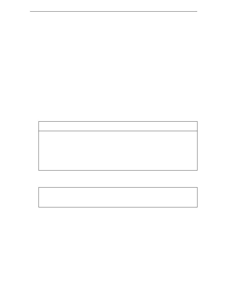
Chapter 21
952
Although these methods by themselves don't look particularly interesting, they do illustrate a general
technique that you'll probably often need to use. With GDI+, we'll often find ourselves in a situation
where we have been given some coordinates (for example the coordinates of where the user has clicked
the mouse) and we'll need to figure out what item is being displayed at that point. Or it could happen
the other way round – given a particular display item, whereabouts should it be displayed? Hence, if
you are writing a GDI+ application, you'll probably find it useful to write methods that do the
equivalent of the coordinate transformation methods illustrated here.
Responding to User Input
So far, with the exception of the
File
menu in the CapsEditor sample, everything we've done in this
chapter has been one way: The application has talked to the user, by displaying information on the
screen. Almost all software of course works both ways: The user can talk to the software as well. We're
now going to add that facility to CapsEditor.
Getting a GDI+ application to respond to user input, is actually a lot simpler than writing the code to
draw to the screen, and indeed we've already covered how handle user input in Chapter 9. Essentially,
you override methods from the Form class that get called from the relevant event handler – in much the
same way that OnPaint() is called when a Paint event is raised.
For the case of detecting when the user clicks on or moves the mouse the functions you may
wish to override include:
Method
Called when
OnClick(EventArgs e)
mouse is clicked
OnDoubleClick(EventArgs e)
mouse is double clicked
OnMouseDown(MouseEventArgs e)
left mouse button pressed
OnMouseHover(MouseEventArgs e)
mouse stays still somewhere after moving
OnMouseMove(MouseEventArgs e)
mouse is moved
OnMouseUp(MouseEventArgs e)
left mouse button is released
If you want to detect when the user types in any text, then you'll probably want to override these
methods.
OnKeyDown(KeyEventArgs e)
a key is depressed
OnKeyPress(KeyPressEventArgs e)
a key is pressed and released
OnKeyUp(KeyEventArgs e)
a pressed key is released
Notice that some of these events overlap. For example, if the user presses a mouse button this will raise
the MouseDown event. If the button is immediately released again, this will raise the MouseUp event and
the Click event. Also, some of these methods take an argument that is derived from EventArgs, and
so can be used to give more information about a particular event. MouseEventArgs has two properties
X
and Y, which give the device coordinates of the mouse at the time it was pressed. Both
KeyEventArgs
and KeyPressEventArgs have properties that indicate which key or keys the event
concerns.

Graphics with GDI+
953
That's all there is to it. It's then up to you to think about the logic of precisely what you want to do. The
only point to note, is that you'll probably find yourself doing a bit more logic work with a GDI+
application than you would have with a Windows.Forms application. That's because in a
Windows.Forms
application you are typically responding to quite high-level events (TextChanged for
a text box, for example). By contrast with GDI+, the events tend to be more basic – user clicks the
mouse, or hits the key h. The action your application takes is likely to depend on a sequence of events
rather than a single event. For example, in Word for Windows, in order to select some text the user will
normally click the left mouse button, then move the mouse, then release the left mouse button. If the
user simply hits, then releases the left mouse button Word doesn't select any text, but simply moves the
text caret to the location where the mouse was. So at the point where the user hits the left mouse button,
you can't yet tell what the user is going to do. Your application will receive the MouseDown event, but
assuming you want your application to behave in the same way that Word for Windows does, there's
not much you can do with this event except record that the mouse was clicked with the cursor in a
certain position. Then, when the MouseMove event is received, you'll want to check from the record
you've just made whether the left button is currently down, and if so highlight text as the user selects it.
When the user releases the left mouse button, your corresponding action (in the OnMouseUp() method)
will need to check whether any dragging took place, while the mouse was down and act accordingly.
Only at this point is the sequence complete.
Another point to consider, is that because certain events overlap, you will often have a choice of which
event you want your code to respond to.
The golden rule really is to think carefully about the logic of every combination of mouse movement or
click and keyboard event which the user might initiate, and ensure that your application responds in a
way that is intuitive and in accordance with the usual expected behavior of applications in every case.
Most of your work here will be in thinking rather than in coding, though the coding you do will be quite
fiddly, as you may need to take into account a lot of combinations of user input. For example, what
should your application do if the user starts typing in text while one of the mouse buttons is held down?
It might sound like an improbable combination, but sooner or later some user is going to try it!
For the CapsEditor sample, we are keeping things very simple, so we don't really have any
combinations to think about. The only thing we are going to respond to is when the user double clicks –
in which case we capitalize whatever line of text the mouse is hovering over.
This should be a fairly simple task, but there is one snag. We need to trap the DoubleClick event, but
the table above shows that this event takes an EventArgs parameter, not a MouseEventArgs
parameter. The trouble is that we'll need to know where the mouse is when the user double clicks, if we
are to correctly identify the line of text to be capitalized – and you need a MouseEventArgs parameter
to do that. There are two workarounds. One is to use a static method that is implemented by the Form1
object, Control.MousePosition to find out the mouse position, like so:
protected override void OnDoubleClick(EventArgs e)
{
Point MouseLocation = Control.MousePosition;
// handle double click
In most cases this will work. However, there could be a problem if your application (or even some other
application with a high priority) is doing some computationally intensive work at the moment the user
double clicks. It just might happen in that case that the OnDoubleClick() event handler doesn't get
called until perhaps half a second later. You don't really want delays like that, because they annoy users
really quickly, but even so, such situations do come up occasionally. Half a second is easily enough for
the mouse to get moved halfway across the screen – in which case you'll end up executing
OnDoubleClick()
for completely the wrong location!

Chapter 21
954
A better way here, is to rely on one of the many overlaps between mouse event meanings. The first part
of double clicking a mouse involves pressing the left button down. This means that if
OnDoubleClick()
is called then we know that OnMouseDown() has also just been called, with the
mouse at the same location. We can use the OnMouseDown() override to record the position of the
mouse, ready for OnDoubleClick(). This is the approach we take in CapsEditor:
protected override void OnMouseDown(MouseEventArgs e)
{
base.OnMouseDown(e);
this.mouseDoubleClickPosition = new Point(e.X, e.Y);
}
Now let's look at our OnDoubleClick() override. There's quite a bit more work to do here:
protected override void OnDoubleClick(EventArgs e)
{
int i = PageCoordinatesToLineIndex(this.mouseDoubleClickPosition);
if (i >= 0)
{
TextLineInformation lineToBeChanged =
(TextLineInformation)documentLines[i];
lineToBeChanged.Text = lineToBeChanged.Text.ToUpper();
Graphics dc = this.CreateGraphics();
uint newWidth =(uint)dc.MeasureString(lineToBeChanged.Text,
mainFont).Width;
if (newWidth > lineToBeChanged.Width)
lineToBeChanged.Width = newWidth;
if (newWidth+2*margin > this.documentSize.Width)
{
this.documentSize.Width = (int)newWidth;
this.AutoScrollMinSize = this.documentSize;
}
Rectangle changedRectangle = new Rectangle(
LineIndexToPageCoordinates(i),
new Size((int)newWidth,
(int)this.lineHeight));
this.Invalidate(changedRectangle);
}
base.OnDoubleClick(e);
}
We start off by calling PageCoordinatesToLineIndex() to work out which line of text the mouse
was hovering over when the user double-clicks. If this call returns –1 then we weren't over any text, so
there's nothing to do (except, of course, call the base class version of OnDoubleClick() to let
Windows do any default processing. You wouldn't ever forget to do that, would you?)
Assuming we've identified a line of text, we can use the string.ToUpper() method to convert it to
uppercase. That was the easy part. The hard part, is figuring out what needs to be redrawn where.
Fortunately, because we kept the sample so simplistic, there aren't too many combinations. We can
assume for a start, that converting to uppercase will always either leave the width of the line on the
screen unchanged, or increase it. Capital letters are bigger than lowercase letters therefore, the width
will never go down. We also know that since we are not wrapping lines, our line of text won't overflow
to the next line and push out other text below. Our action of converting the line to uppercase won't
therefore, actually change the locations of any of the other items being displayed. That's a big
simplification!

Graphics with GDI+
955
The next thing the code does is use Graphics.MeasureString() to work out the new width of the
text. There are now just two possibilities:
❑
First, the new width might make our line the longest line, and cause the width of the entire
document to increase. If that's the case then we'll need to set AutoScrollMinSize to the
new size so that the scrollbars are correctly placed.
❑
Second, the size of the document might be unchanged.
In either case, we need to get the screen redrawn, by calling Invalidate(). Only one line has
changed therefore, we don't want to have the entire document repainted. Rather, we need to work out
the bounds of a rectangle that contains just the modified line, so that we can pass this rectangle to
Invalidate()
, ensuring that just that line of text will be repainted. That's precisely what the above
code does. Our call to Invalidate() will result in OnPaint() being called, when the mouse event
handler finally returns. Bearing in mind our comments earlier in the chapter about the difficulty in
setting a break point in OnPaint(), if you run the sample and set a break point in OnPaint() to trap
the resultant painting action, you'll find that the PaintEventArgs parameter to OnPaint() does
indeed, contain a clipping region that matches the specified rectangle. And since we've overloaded
OnPaint()
to take careful account of the clipping region, only the one required line of text will be
repainted.
Printing
In this chapter we've focused entirely on drawing to the screen. Often, you will also want your
application to be able to produce a hard copy of the data too. Unfortunately, in this book we don't have
space to go into the details of this process, but we'll briefly review the issues you'll face if you do wish to
implement the ability to print your document.
In many ways printing is just the same as displaying to a screen: You will be supplied with a device
context (Graphics instance) and call all the usual display commands against that instance. However,
there are some differences: Printers cannot scroll – instead they have pages. You'll need to make sure
you find a sensible way of dividing your document into pages, and draw each page as requested. Also,
beware – most users expect the printed output to look very similar to the screen output. This is actually
very hard to achieve if you use page coordinates. The problem is that printers have a different number
of dots per inch (dpi) than the screen. Display devices have traditionally maintained a standard of
around 96 dpi, although some newer monitors have higher resolutions. Printers can have over a
thousand dpi. That means, for example, that if you draw shapes or display images, sizing them by
number of pixels, they will appear too small on the printer. In some cases the same problem can affect
text fonts. Luckily, GDI+ allows device coordinates to address this problem. In order to print
documents you will almost certainly need to use the Graphics.PageUnit property to carry out the
painting using some physical units such as inches or millimeters.
.NET does have a large number of classes designed to help with the process of printing. These classes
typically allow you to control and retrieve various printer settings and are found mostly in the
System.Drawing.Printing
namespace. There are also predefined dialogs, PrintDialog and
PrintPreviewDialog
available in the System.Windows.Forms namespace. The process of printing
will initially involve calling the Show() method on an instance of one of these classes, after setting
some properties.

Chapter 21
956
Summary
In this chapter, we've covered the area of drawing to a display device, where the drawing is done by
your code rather than by some predefined control or dialog – the realm of GDI+. GDI+ is a powerful
tool, and there are a large number of .NET base classes available to help you draw to a device. We've
seen that the process of drawing is actually relatively simple – in most cases you can draw text or
sophisticated figures or display images with just a couple of C# statements. However, managing your
drawing – the behind the scenes work involving working out what to draw, where to draw it, and what
does or doesn't need repainting in any given situation – is far more complex and requires careful
algorithm design. For this reason, it is also important to have a good understanding of how GDI+ works,
and what actions Windows takes in order to get something drawn. In particular, because of the
architecture of Windows, it is important that where possible, drawing should be done by invalidating
areas of the window and relying on Windows to respond by issuing a Paint event.
There are many more .NET classes concerned with drawing than we've had space to cover in this chapter,
but if you've worked through and understood the principles involved in drawing, you'll be in an excellent
position to explore them, by looking at their lists of methods in the documentation and instantiating
instances of them to see what they do. In the end, drawing, like almost any other aspect of programming,
requires logic, careful thought and clear algorithms. Apply that and you'll be able to write sophisticated
user interfaces that don't depend on the standard controls. Your software will benefit hugely in both user-
friendliness and visual appearance: There are many applications out there that rely entirely on controls for
their user interface. While this can be effective, such applications very quickly end up looking just like
each other. By adding some GDI+ code to do some custom drawing you can mark out your software as
distinct and make it appear more original – which can only help your sales!

Graphics with GDI+
957

Chapter 21
958
Wyszukiwarka
Podobne podstrony:
Graphics with Maxima
(eBook) MatLab 7 Creating Graphical User Interfaces Q3G75XKESYH7ITRH7DEMLBB5TCOT55MEKC7G6QI
Ebook Creating Wap Applications With Delphi
Tutorial Photoshop Combining Illustrator Graphics With Photoshop Images
kurs excel (ebook) statistical analysis with excel X645FGGBVGDMICSVWEIYZHTBW6XRORTATG3KHTA
(ebook) Internet Programming With Delphi 55FZBF6IRWTY6IV67FPLXBQ6ZSLYVNNNTPVZFOA
Apress Database Programing With C Sharp
L 5008 Jacket with sharp collar
Creating Custom Net Controls With C Sharp
M 5008 Jacket with sharp collar
(ebook pdf) Engineering Numerical Analysis with MATLAB FMKYK6K23YGTTIMP3IT5M4UO4EKLFJQYI4T3ZRY
kurs excel (ebook) statistical analysis with excel X645FGGBVGDMICSVWEIYZHTBW6XRORTATG3KHTA
(Ebook English) Crafts Beading Working With Metal Clay
sekrety jezyka c c sharp darmowy ebook pdf
Exam 070 320 Mcsd Mcad Xml Webservices And Server Components With C Sharp Net (V 6 0)
grandpa acrostic lined with graphic
więcej podobnych podstron