
Easicheck 2 Planning Guide Rev2.Doc
P a g e
| 1
EASICHECK 2
Planning Guide
1.0 Overview
Easicheck2 is an addressable emergency lighting testing system. Each Easicheck2 panel is designed
to operate with up to 200 addressable test interfaces connected on a data circuit, for larger sites
control panels can be networked together to function as a single system (see section 4.0).
Connections between the control panel and the Easicheck2 interfaces, is by means of a 2 core
twisted pair cable.
Fittings for use with Easicheck2 must be fitted with a suitable Easicheck2 test interface, this interface
MUST be fitted by Cooper Lighting and Safety, fitting of the interface by others is not acceptable and
can result in a system malfunction. When fitted by Cooper Lighting and Safety careful checks are
carried out to ensure the test interface is fully compatible with the fitting and has been correctly
installed.
1.1 Location of control panel
When selecting a location for the Easicheck2 control panel it should be noted that the panel
incorporates a maintenance free lead acid battery, the panel should therefore be located in a clean
dry environment with an ambient temperature of between 5
o
C and 25
o
C
2.0 Data Cable planning
This section relates to the data cable for the connection of the addressable interfaces to the main
control panel. Two way communication takes place along this cable and although the Easicheck2
system protocol is extremely robust, careful attention to the following points is essential to ensure
reliable operation.
2.1 Choice of cable type
The cable used to connect Easicheck2 interfaces to the Easicheck2 control panel must be an
unscreened 2 core twisted pair cable. The recommended data cable type is Belden type 8471, or
alternatively if a LSZH type cable is required, Belcom cables type 4001P1644 (16AWG) can be also
used. Other cable types can be used providing they fully meet the following performance
requirements:
1) It must be an unscreened 2 core twisted pair cable.
2) It is not acceptable to include additional cores, which are left unconnected or used for other
systems or other Easicheck2 panels.
3) The total capacitance of all cable connected to the data loop must not exceed 1µF, this is best
verified by calculation, cable manufacturers data should specify the total core to core capacitance per
km and this should then be multiplied by the total length of connected cable.
2.2 Cable volt drop limitations
The worst case volt drop between the loop terminals on the panel and any other point on the system
must not exceed 10V.
For calculation purposes the average current consumption of an Easicheck2 interface may be taken
as 0.0012A Typical cable size for the data circuit will be 1 – 2.5mm
2
depending on the number of
connected devices, circuit configuration and length of cable runs
Easicheck 2 Planning Guide Rev2.Doc
P a g e
| 2
2.3 Installation of data cable
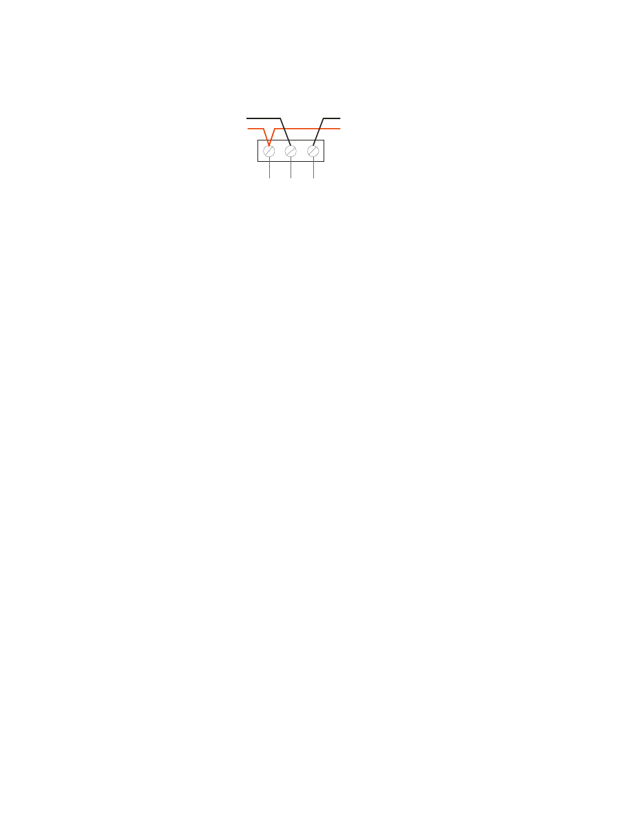
1) Due to the soft addressing functionality of the Easicheck2 2 System it is imperative the loop
connections are as per Fig 2.1 below with a common positive connection and –Ve Loop in/out are
observed. When loop connections are installed incorrectly the system will fail to soft address
luminaires.
L
O
O
P
+
V
e
L
O
O
P
I
N
L
O
O
P
O
U
T
IN
OUT
LUMINAIR DATA LOOP
WIRING DETAIL
+Ve
-Ve
+Ve
-Ve
Fig 2.1
2) Avoid running the cable within 500mm of cables operating at above 240V with respect to Neutral
and from heavy current switching devices such as motor control equipment.
2.4 Circuit configuration
2.4.1 Loop circuit
To facilitate the soft addressing function and improved circuit integrity of the Easicheck 2 system a
loop configuration must be used, however radial circuits can be utilises (see section 2.4.2 – Combined
loop/radial arrangement).
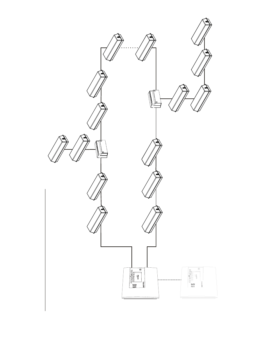
2.4.2 Combined loop / radial arrangement
With this method a loop is run between the start and end terminals of the panel and the interfaces are
then connected by spurs running from various points on the loop using a Spur isolator See Diagram
2.2. Experience has shown that a combined loop circuit with multiple spurs is the simplest in terms of
installation planning and fault finding. When soft addressing occurs, addressing continues from start
of the loop until a spur isolator is encountered and diverts addressing sequence along the spur leg.
When all luminaires within the spur have been addresses, addressing returns to the next luminaire
following the spur isolator. See Diagram 2.2 for wiring detail of the combined loop/radial arrangement.
Easicheck 2 Planning Guide Rev2.Doc
P a g e
| 3
M
A
X
IM
U
M
N
U
M
B
E
R
O
F
D
E
V
IC
E
S
I
N
L
O
O
P
=
2
0
0
(I
N
C
L
U
D
IN
G
R
A
D
IA
L
C
IR
C
U
IT
S
)
S
P
U
R
I
S
O
L
A
T
O
R
E
A
S
IC
H
E
C
K
2
D
A
T
A
B
U
S
W
IR
IN
G
D
E
T
A
IL
M
S
I1
8
0
E
C
S
P
U
R
I
S
O
L
A
T
O
R
M
S
I1
8
0
E
C
F
ig
2
.2
T
y
p
ic
a
l
lo
o
p
c
ir
c
u
it
–
N
.B
.
fo
r
c
la
ri
ty
i
n
d
iv
id
u
a
l
c
o
n
d
u
c
to
rs
a
re
n
o
t
s
h
o
w
n
Easicheck 2 Planning Guide Rev2.Doc
P a g e
| 4
2.5 Volt drop and capacitance calculations.
2.5.1 Loop arrangement
The maximum allowable volt drop to the furthest point on the system is 10V and can be confimed
using the formula below, however since the loop is driven from both ends, assume for calculation
purposes that half of the current flows in each half of the loop, therefore, the current per interface can
be halved.
Km
per
impedance
cable
Interfaces
No
Km
Cable
Length
Max
_
_
_
.
0012
.
0
10
)
(
_
_
×
×
=
It should also be noted that the resulting maximum cable length calculated will be for each half of the
loop i.e. the distance will equate to the furthest point from the panel rather than the total amount of
cable. Based on the suggested cable types which have a DC resistance of 30Ω / km, and assuming a
fully loaded system (200 fittings) the maximum allowable cable length would be:
kM
77
.
2
)
30
12
.
0
(
10
=
×
This equates to 2.77km of cable on the go leg and a further 2.77km of cable on the return leg.
Verification of total capacitance.
The core to core capacitance of the suggested cable is 0. 11 µF / km, the maximum allowable
connected capacitance is 1µF, therefore the maximum amount of the suggested cable that can be
connected whilst remaining within the capacitance limit is 9km therefore the total of 4.44km would be
well within the allowable limit
2.5.2 Using a combined arrangement
From the above it can be seen that a loop arrangement helps to limit volt drop but can result in large
amounts of cable being installed, which increases the total amount of capacitance.
In many cases an ideal compromise will be found in the form of a combined arrangement consisting of
a relatively short loop with a number of connected spurs.
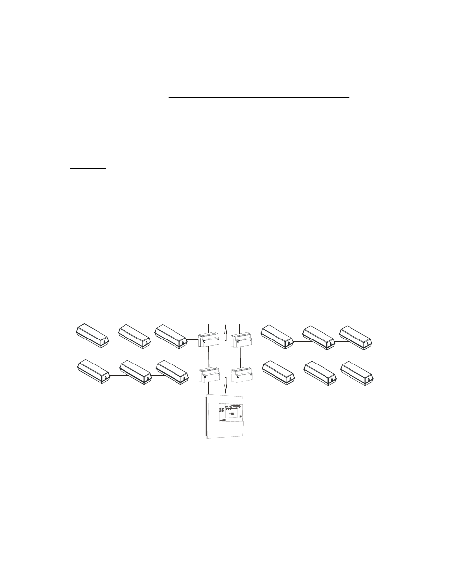
Consider an installation consisting of a loop of cable which is 100 meters in length (from the panel to
the furthest point) and feeds 4 spurs each having 50 connected Easicheck2 interfaces.
MSI18
0EC
MSI18
0EC
MSI1
80EC
MSI1
80EC
1
0
0
M
E
T
E
R
S
50 LUMINAIRES PER SPUR
The worst case volt drop at any point on the system must not exceed 10V, it is therefore necessary to
first calculate the volt drop to the furthest point in the loop and then it is possible to calculate the
allowable length of each spur based on the remaining maximum allowable volt drop.
Because the 100 Metre loop is driven from both ends, it can be assumed that half of the total current
flows in each half of the loop so for calculation purposes the individual current per interface can be
halved, therefore the volt drop to the furthest point will be:

Easicheck 2 Planning Guide Rev2.Doc
P a g e
| 5
No of interfaces (200) X (Current per interface X 0.5)[0.0006] X cable resistance per KM (30Ω) X
distance to furthest in point km (0.1) = 0.36V.
The maximum allowable volt drop is 10V so the maximum volt drop on each spur is 9.64V. Feeding
this into the standard spur volt drop calculation gives the following values
Km
per
impedance
Cable
Interfaces
No
Km
Cable
Length
Max
_
_
_
.
0012
.
0
64
.
9
)
(
_
_
×
×
=
Based on a of the suggested type, with an resistance of 30Ω / km, and 50 fittings on the spur the
maximum allowable cable length would be:
Km
3
.
5
)
30
06
.
0
(
64
.
9
=
×
Verification of total capacitance.
The core to core capacitance of the suggested cable is 0. 11 µF /Km, the maximum allowable
connected capacitance is 1µF, therefore the maximum amount of the suggested cable that can be
connected whilst remaining within the capacitance limit is 9km
For this example based on 5 circuits, although the maximum length of any one circuit could be up to
6.1km whilst still remaining within the volt drop limit, the total amount of cable connected to the panel
must not exceed 9km in order to remain within the capacitance limit.
3.0 Short circuit isolators function (integral to luminiare)
With typical addressable testing systems, a single short circuit will completely disable communication
between the panel and the luminaires. For this reason short circuit isolators are incorporated into
each Easicheck 2 luminaire interface and a short circuit in any section of the data loop will only
eliminate one luminiare from the testing system and will be highlighted with a faulty comms error on
the Easicheck 2 panel. Short circuit isolators are always incorporated into the panel to provide short
circuit isolation at the very start and end of the loop
In the event of a short circuit occurring, short circuit isolators at either side of the luminaire will open
circuit eliminating the short circuit section of the data bus and allow all other interface s to
communicate
3.1 Use of Crowbar devices
The Easicheck2 data circuit operates at a nominal 24V. If mains voltage is connected to the data loop
then it is likely that equipment will be damaged, and there is a risk of electric shock if the 24V circuit is
inadvertently touched.
There are two potential areas of risk:
a. If 240v is connected across the 24v circuit equipment will be damaged due to over-voltage.
b. If one side of the 24v circuit is connected to 240v all the equipment becomes live.
The connection to mains may be from a wiring error, damaged insulation or water ingress. Crowbar
devices (EC210) constantly monitor the voltage of the data circuit and if mains voltage is detected, the
crowbar device will immediately clamp both sides of the data circuit together and then to earth,
preventing any over-voltage being applied to the Easicheck2 interfaces and also causing the
protective device upstream of the live supply to operate. For Crowbar devices to operate correctly
they must be positioned with a cable length between each crowbar unit of 500m maximum.
4.0 Networking of panels
A single Easicheck2 panel can accommodate up to 200 interfaces, if a greater number are required
then additional panels will be required. If multiple panels are used and there is a requirement to view
the entire system status or control the entire system from a single point, then it is necessary to
network the panels together. Both central battery system panels and self contained system panels
can be networked together, a network can contain a mixture of self contained Easicheck2 panels and
Central battery system Easicheck2 panels.
Easicheck 2 Planning Guide Rev2.Doc
P a g e
| 6
Self contained and Central battery system panels can be mixed in any combination subject to a
maximum of 63 panels in total.
networking requires use of Easicheck2 control panels that have been factory modified to make them
network compatible and which are then connected together using a suitable network cable.
The network cable connects Easicheck2 control panels together and should not be confused with the
data cable, which connects Easicheck2 control panel to luminaire interfaces.
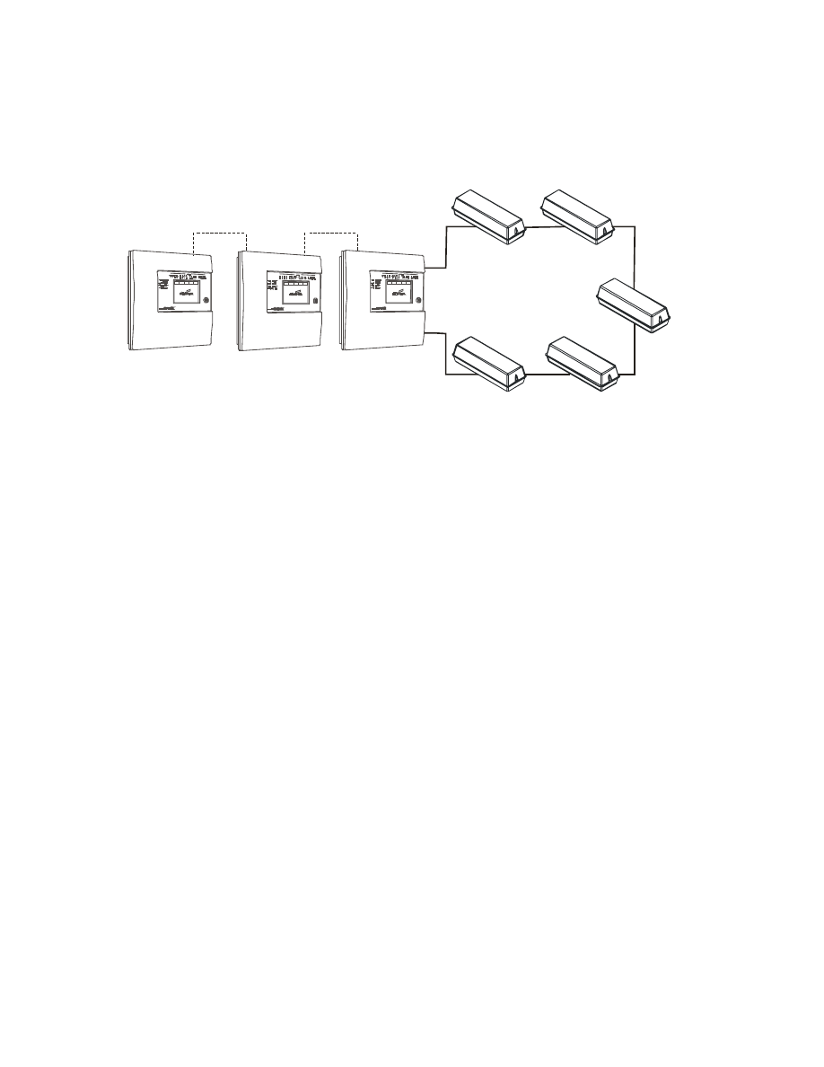
Networked Easicheck2 panels should be connected in a radial spur topology as detailed above
DATA LOOP
NETWORK CABLE
NETWORK CABLE
4.1 Network system planning
When networking the above panels there are a number of important considerations that relate to the
cable type, cable length and ancillary equipment required to achieve reliable networking.
4.1.1 Recommended cable type
The recommended cable for the network connection is a Belden cable type 8719 CL2 (screened
cable)
4.1.2 Installation of Network cable
Screen continuity must be maintained throughout the entire network circuit including at each junction
point. The screen should only be earthed at the connection point provided at the first Easicheck2
panel and not at any other point. The screen or drain wire of the network cable should not be
considered as a safety earth and therefore should not be connected to terminals marked with the
earth symbol, except at the panel, and should not be insulated with green and yellow sleeving Where
the network cable passes between buildings, screen continuity should not be maintained from building
to building. A booster device must however be used irrespective of cable length and should be fitted
at a suitable point in the link between buildings. The cable screen should be connected to the earth of
one Easicheck2 panel in each building.
4.1.3 Acceptable Cable length.
Based on the above cable, the maximum acceptable length between signal boosters is 1500 Metres.
This distance can only be achieved when the above cable is used, Cooper lighting and safety does
not recommend the use of other network cables
.
Once the maximum cable length has been reached, a booster must be fitted which then allows a
further length of the same distance (1500 Metres for the recommended cable). A maximum of 3
network boosters can be used
N.B. Easicheck2 control panels do not act as boosters, therefore the location of such panels is
irrelevant when calculating cable lengths and the requirement for booster devices. For convenience
when using 24V boosters (see following) it may be desirable to house the booster near to an
Easicheck2 panel to derive a convenient power supply.
4.1.4 Central Reporting
With a networked system, any luminaire or system fault that occurs, is transmitted around the system
and displayed on every panel connected to the network. A fully loaded networked system could
contain as many as 63 panels each with up to 200 connected fittings giving a maximum system
capacity of 15,750 fittings. Easicheck2 panels have only limited capacity for storing and displaying
Easicheck 2 Planning Guide Rev2.Doc
P a g e
| 7
fault information, and whilst this is perfectly adequate for most normal projects, on large projects
where full central reporting is required, a central computer system should be incorporated. Cooper
Lighting and Safety offer a choice of two computer software packages, either site monitor or colour
graphics software.
These software systems are purpose designed for this application and can accept, handle
summarise, filter, display and store all information from even the largest of projects.
This provides a simple clear overview of the status of the emergency lighting system on even the very
largest of projects. Both of these systems are supplied complete with all necessary software and
externally mounted hardware to enable installation onto a host computer that is normally provided by
others. Site monitor is a standard text based off the shelf package, all device status and location
information is collected directly from the network so no setting up or programming is required. The
colour graphics package is a bespoke system designed to show the physical location of system
components which are in need of attention on a series of maps. These systems utilise site specific
maps and are quoted on a project specific basis
There is no set point at which these systems must be used, but as a rule of thumb, on a networked
system that has a total of more than 500 fittings and a requirement for central reporting of the entire
system status, a computer software package is highly recommended.
4.2 Booster devices
Two types of booster are available, both have a similar function except that one is powered by a 24V
supply and the other is powered from a local mains supply. However it should be noted that the
network will cease to function if the booster loses power therefore for most applications the 24V
device would be more suitable and would be connected to a battery backed supply such as the
auxiliary DC output of an Easicheck2 panel. Booster Device details
Part number Description
Part Number
Description
7660-3250
24V LONWORK REPEATER
4.3 Non Standard networking options
The standard method of networking Easicheck2 is by means of a hard wired connection as detailed
above. For applications where this is not suitable, other options are available consisting of either Fibre
optic or TCP/IP interfaces.
4.3.1 LON to TCP/IP interface (EC400)
This device enables an Easicheck2 Network circuit to be connected into the IT infrastructure of a site
and then to re-emerge later via a second TCP/IP to LON interface at a further point whereby it reverts
to a hard wired connection. Providing a suitable permanent IT connection is available, this facility
enables Panels located in different buildings to communicate with each other without the need for a
dedicated hard wired link between the panels.
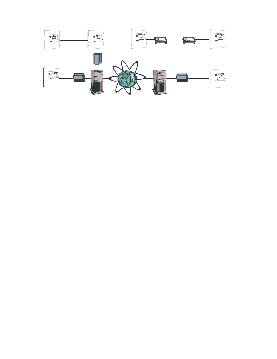
4.3.2 LON to fibre Optic interface (EC450)
This device offers a similar facility to that of EC400 except that the connecting medium between the
two devices would be a fibre optic link as opposed to an IT network or the internet. Easicheck2
Easicheck 2 Planning Guide Rev2.Doc
P a g e
| 8
Typical applications for the above are detailed in the schematic diagram below
Server
Server
EC400
Fibre optic link
EC400
EC400
EC450
EC450
Permanent IT connection
5.0 Device programming
As a alternative to soft addressing as a means of automatically assigning an address to each
luminiare it is possible for Eaischeck2 interfaces to be programmed manually using CF800ECPROG
programmer. Once the system has been commissioned and location text has been assigned to each
address, the Easicheck2 system is then able to identify the physical location of any luminaires
requiring attention. If manual programming of Easicheck 2 interfaces is required it is the responsibility
of the system installer and should be carried out as the luminaires are being installed.
Interface programming is achieved by means of a custom designed hand held programmer unit
supplied by Cooper Lighting and Safety, +Ve and _Ve connections of the hand held programmer are
connected to the data input connections of the interface to enable two way communication to take
place between the programmer and the interface.
Programming of interfaces must be carried out before connecting the data cable to the
interface.
Luminaires must never be programmed with the data cable connected, as this will cause the same
address number to be programmed into multiple luminaires resulting in system malfunction.
When planning the programming of a system, it should be noted that address numbers should be
used in order, i.e. no gaps in the address number sequence are allowed, and care should be taken to
ensure that no addresses are duplicated.
IMPORTANT NOTE
To avoid confusion; it is essential that drawings are marked up prior to commencing
programming and installation with detail indicating the address number to be used for each
emergency device and cable as-fitted drawings be kept. It is then possible during installation
and programming to verify that the correct device with the correct address number is installed
at each location. Commissioning and installation fault finding will be greatly simplified if
luminaires are installed such that the address numbers follow a sequential order. Please note
Cooper Lighting and Safety Commissioning does not include for fault finding, identification or
rectification of installed components and should be error free prior to attendance to site.
5.1 Device labelling
After a device has been programmed a label should be affixed to the device recording the details of
the address number of the device and the panel number to which it has been connected.
Wyszukiwarka
Podobne podstrony:
LG 42V7 Module Plasma TV Service Guide Rev2
Microsoft Dynamics CRM Online security and compliance planning guide
strategic planning guide
Red Hat Enterprise Linux 6 Migration Planning Guide en US
Red Hat Enterprise Linux 6 Migration Planning Guide en US
Complete Guide to Lesson Planning and Preparation
Microsoft Assessment and Planning Toolkit 4 0 Usage Tracker Guide en
Microsoft Assessment and Planning Toolkit 4 0 Getting Started Guide en
Everyone S Guide To Financial Planning
guide camino aragones pl
Herbs for Sports Performance, Energy and Recovery Guide to Optimal Sports Nutrition
Meezan Banks Guide to Islamic Banking
NLP for Beginners An Idiot Proof Guide to Neuro Linguistic Programming
freespan spec guide
Eaton VP 33 76 Ball Guide Unit Drawing
Herbs to Relieve Headaches Keats Good Herb Guide
50 Common Birds An Illistrated Guide to 50 of the Most Common North American Birds
Configuration Guide WAN Access(V100R006C00 02)
więcej podobnych podstron