1
Bandpass receiving loops for 136kHz and 500kHz
- Jim Moritz, M0BMU
Some years ago, I designed receiving loop antennas with a bandpass characteristic to cover the whole 136kHz
band without the need for remote tuning (see “Bandpass receiving loop antennas”, available at
http://www.wireless.org.uk/bploop.pdf
). These have given good service, but the designs are now difficult to
reproduce because the ferrite pot cores used are no longer available. Also, the 500kHz band has subsequently
come into being. This article describes updated designs for 1 metre square loops covering the 136kHz and
500kHz bands, with sensitivity limited only by external band noise.
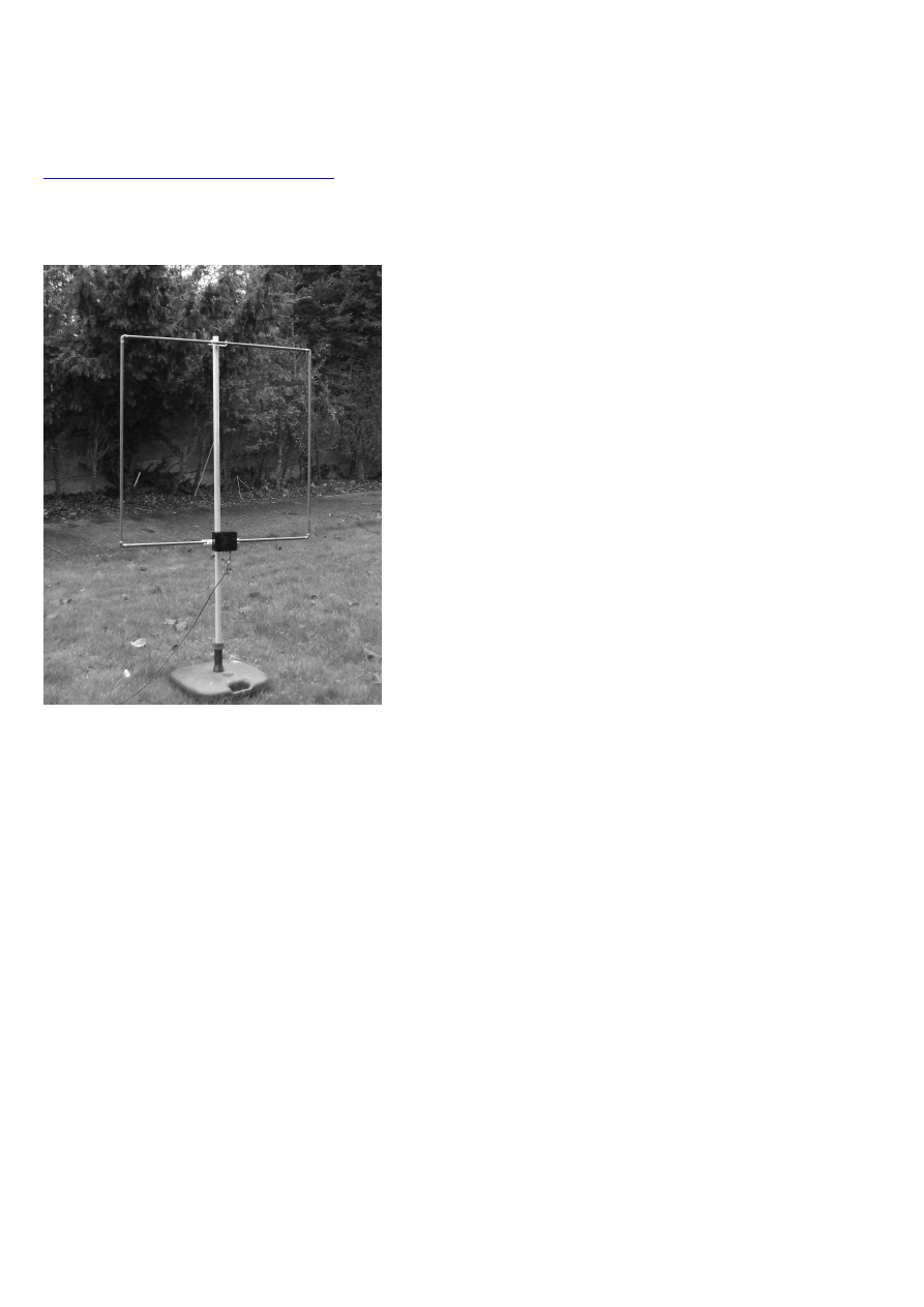
Figure 1 – 1m
2
bandpass loop antenna
The traditional tuned loop antenna is a high Q tuned circuit, usually buffered with a high impedance preamp.
This gives a useful preselector action along with directional nulls and small size. It also has drawbacks; even
for use over 135.7kHz – 137.8kHz, it is necessary to peak the tuning, since the bandwidth is usually less than
1kHz. Since it is usually necessary to locate the loop away from the operating position to avoid high noise
levels from mains wiring, this requires some sort of remote tuning. Remote tuning can be avoided by resistively
loading the loop to reduce the Q, but this reduces the output signal-to noise ratio and also out-of-band
selectivity is degraded. At M0BMU selectivity is an important factor, since the field strength due to the local
MF broadcast stations is of the order of 10s of volts per metre.
The tuned loop is essentially a single tuned circuit made up of the inductance of the loop and a resonating
capacitor. The magnetic flux component of the radio signal induces an EMF in the loop inductance. It can be
made into a bandpass filter by coupling it to the receiver via additional tuned circuits. The advantages of this
are that:
• The circuit can be designed to have a flat-topped frequency response covering the desired frequency
range without tuning adjustment.
• The resistive loading required to achieve the desired bandwidth is somewhat reduced, improving SNR
with a given size of loop.
• Rejection of unwanted signals outside the passband is increased.
In principle, you could use any number of coupled tuned circuits, the main effect of having more being to
increase out-of-band rejection further. But more tuned circuits means increased losses and complexity, and in
practice a “2 pole” filter configuration using the resonant loop itself and a single auxiliary resonant circuit
seems adequate for most purposes.
2
Based on previous experience, I wanted to use a single-turn square loop element made from 15mm water pipe.
This is easy to make, easy to weatherproof, and robust. The main difficulty is that, with an inductance of only
3.6
µH, such a loop requires large resonating capacitors, about 30nF for 500kHz and 400nF for 136kHz.
However, since tuning only has to be set up once, it is quite easy to get the correct values by connecting smaller
capacitors in parallel. If metallised polypropylene or polystyrene capacitors are used, the unloaded Q of such a
loop will be well over 100, which is more than adequate. A very high tuning capacitance also means the loop is
unlikely to be de-tuned by stray capacitance effects, also the resulting low impedance reduces the likelihood of
E-field noise being picked up, and simplifies matching to a 50
Ω load. Suitable LF/MF adjustable inductors and
trimmer capacitors are becoming more and more scarce. In these designs, the auxiliary tuned circuit inductors
are the primaries of “Toko” or similar 455kHz IF transformers, which are fairly easy to find.
Circuit Details
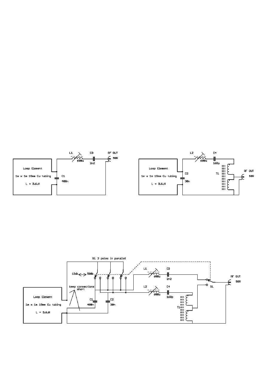
Figure 2 shows similar circuits are used for both 136kHz and 500kHz loops, with the same inductance values
for both. The 500kHz loop includes a 2:1 turns ratio transformer to increase the load seen by the loop circuit
from 50
Ω to 200Ω, while the 136kHz circuit is loaded with 50Ω directly. This gives roughly similar loaded Q
for both bands, although the 500kHz loop has wider bandwidth due to the higher frequency. The transformer
design is not critical; any transformer giving a low loss and 200
Ω:50Ω transformation at 500kHz could be used.
The –3dB bandwidths of the prototypes were approximately 10kHz for the 136kHz version, and 37kHz for the
500kHz version.
(a) (b)
Figure 2 (a) 136kHz, (b) 500kHz loop circuits
A band-switched version has also been built, see Figure 3. This simply switches one loop element between the
two circuits. A point to note is that the band-change switch selecting the loop resonating capacitor must have
low contact resistance in order not to increase the losses in the loop. For this reason, I used a 4 pole, double
throw toggle switch with three poles connected in parallel to select the loop capacitor. The fourth switch pole at
the output is not critical in this respect.
Figure 3 Band-switched 136kHz/500kHz loop
3
Component Notes
C1
4 x 100nF, 100V metallised polypropylene in parallel (capacitors selected during alignment)
C2
2 x 15nF polystyrene in parallel (capacitors selected during alignment)
C3
2.2nF polypropylene
C4
150pF polystyrene + 18pF in parallel
L1, L2
Primary winding of 455kHz 10mm “Toko” IF transformer with 180pF tuning capacitor or
similar; capacitor removed.
S1 4PDT miniature toggle switch
T1 18 bifilar turns on FT–50–43 (5943000301) 12.7mm dia,
µ = 850 toroid, or similar.
The capacitors should be polystyrene, polypropylene, silver mica or similar stable low-loss types; for the higher
values, metallised polypropylene are the best choice. Polyester (“mylar”) capacitors look the same as
polypropylene, but have much higher loss, so beware! C1 in the prototypes was made up of 4 capacitors in
parallel; it was found that several small capacitors in parallel have less RF resistance than one large capacitor.
The 600
µH adjustable inductors are the primary windings of “Toko” or similar 455kHz IF transformers; the
types that have 180pF capacitors have a suitable inductance value that is adjustable over a fairly wide range.
The internal ceramic capacitor must be disconnected or removed; in the Toko types, this is most easily done by
carefully breaking up the ceramic capacitor in the moulded plastic base with a pointed implement. The primary
winding is usually connected to the two end pins of the row of three pins on the IFT base – check with an
ohmmeter to find the largest winding resistance. Other coils with similar inductance and a Q >50 could be used.
The loop element is made from 4 x 1m lengths of 15mm copper water pipe, joined in a square with 90
0
elbows.
Soldered elbows were used; compression fittings are also feasible, but my experience is that they can work
loose over time. One side of the loop is cut in the middle, the cut ends flattened and drilled, and brass bolts
passed through and soldered into place. The bolts pass through the wall of a plastic box containing the tuning
components, and connections are made using solder tags. This gives a good low-resistance connection. The
connections to the loop tuning capacitors should be as short as possible and direct to the loop terminals,
especially for the band-switched version. Other construction is not critical, and the other components were
mounted on scraps of un-etched PCB material – see Figure 4. The loop element is attached to a wooden support
using plastic pipe clips.
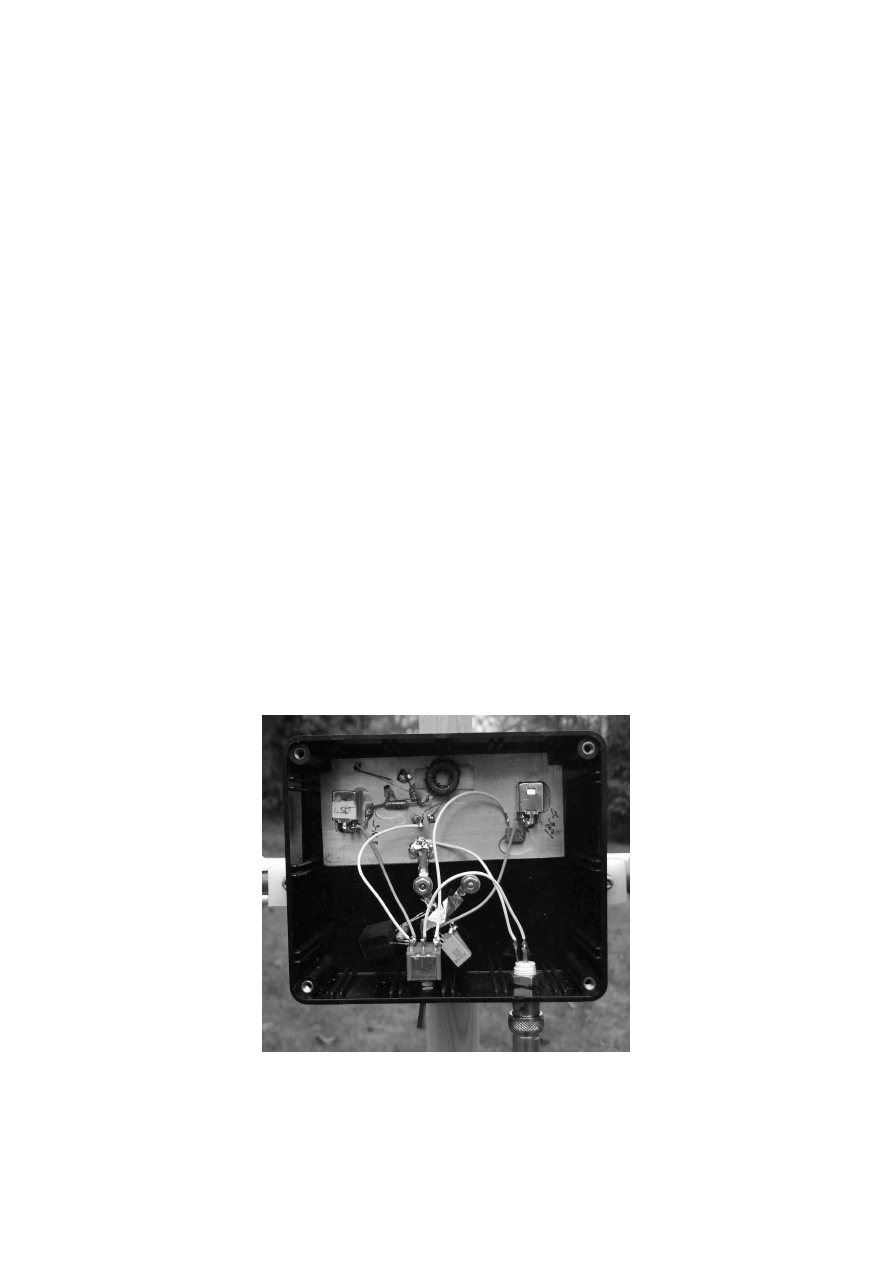
Figure 4 Band-switched loop construction
The loop connections are the two bolts at the back of the case. The loop tuning capacitors C1 and C2 are
mounted on the toggle band switch at the bottom
4
Alignment
Alignment consists of adjusting the resonant frequencies of the loop and auxiliary tuned circuits. This is best
done during assembly by temporarily configuring the tuned circuits as parallel or series traps as in Figure 5;
when the resonant frequency is equal to the source frequency, a sharp dip in detector level will be seen. First,
the parallel resonant frequency of the loop itself is adjusted to be close to the centre of the band of interest by
selecting a suitable parallel combination of capacitors (Figure 5(a)). The auxiliary tuned circuit is then adjusted
to an identical series resonant frequency by itself (Figure 5(b)). Then the connections between the tuned circuits
and the output are made to complete the circuit; no further adjustment should be required. Nominal resonant
frequencies for the two bands are 137kHz and 504kHz, although deviations of a couple of percent from these
values are not serious due to the fairly wide passband – the main thing is that both tuned circuits are set to the
same frequency.
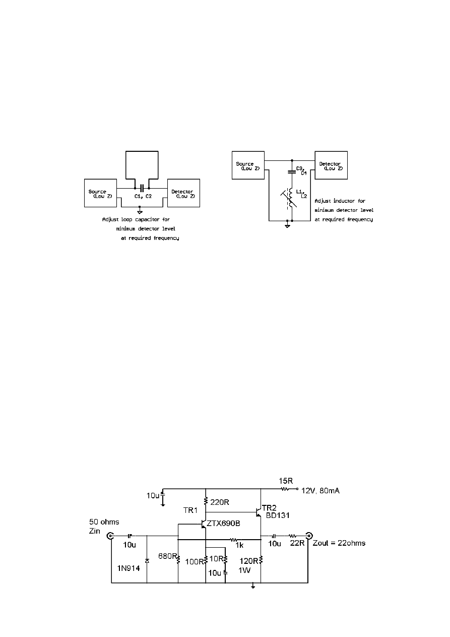
(a) (b)
Figure 5 Adjusting resonant frequency of (a) loop, (b) auxiliary tuned circuit
The “source” and “detector” can be almost anything capable of generating a reasonable test signal at the
frequencies of interest, and indicating a dip in signal level at resonance of the order of 10 – 20dB. A receiver
and a suitable signal generator or wideband noise generator, a signal generator or attenuated TX output with an
oscilloscope or RF voltmeter as detector are examples. The ideal tool is a selective level meter with tracking
generator. Note that, when tuning the Toko inductors, these tiny ferrite cores can be saturated by quite low
signal levels; about –20dBm from the source is safe.
Preamplifier
As with all small loops, output level to the receiver is small – the band noise floor can be below 0.05
µV in a
CW bandwidth from this design. Most receivers are not sensitive enough to be used with these loops without a
low-noise preamp. The preamp should have input impedance near 50
Ω, and a gain around 20dB or so seems to
suit most “reasonable” receivers (sensitivity of a fraction of a microvolt for 10dB SNR in CW bandwidths). The
preamp in Figure 6 was designed for the original loops and has given good results. It has a quite low noise
level; less than 0.02
µV with 50Ω source impedance. Due to the use of negative feedback and a fairly high bias
current, it also has good linearity, and will overload most receivers before generating significant distortion
products. The input impedance is determined by feedback and is close to 50
Ω. The output impedance is roughly
that of the 22
Ω series resistor, which ensures stability with capacitive loads. With 50Ω load, gain is about
22dB. This is essentially a VLF – MF preamp; gain is flat between about 10kHz and a few MHz.

5
Figure 6 Preamplifier Circuit
The ZTX690B is the best device I have found so far for this circuit; if you want to use something else, look for
a small power device with a very high
β
at high bias current, and a f
T
of at least 50MHz – the ZTX 690B has
minimum
β
of 400 at 1A. The ZTX650 worked well too. A 2N3019 in the junk box was only slightly worse.
Devices like the 2N2222 will work, but will generate a couple of dB higher noise level. TR2 is less critical; it
should have
β > 50, f
T
> 50MHz, and be able to dissipate about 1W. A 2N3053 and a BFY51 worked fine.
The Antennas In Use
The prototype loop antennas gave the following responses:
136kHz antenna:
3dB down at 131.6kHz and 141.4kHz, BW 9.8kHz.
30dB down at 113kHz and 181kHz.
500kHz antenna:
3dB down at 484kHz and 521kHz, BW 37kHz
30dB down at 415kHz and 726kHz.
The selectivity of these loops therefore gives useful rejection of LF and MF broadcasters and utilities such as
Loran C. Performance on both bands is good enough to hear the band noise at M0BMU, without overloading
due to the local broadcast stations.
The loop antennas and preamplifier have been used successfully with a variety of receivers including a Racal
RA1792, an Icom IC-718, modified “Softrocks” and various homebrew converters and transverters. It is
important to realise that many amateur-type HF rigs, although providing coverage of the LF/MF range, have
degraded sensitivity at low frequencies. The IC-718 has sensitivity about 20dB down at 136kHz compared to its
HF performance, and the loop preamp gain is marginally enough to cope with this. I have also used the Yaesu
FT-817, which has such poor sensitivity in the LF range that it is much better to use it with a LF/MF to HF up-
converter. The RA1792 has good sensitivity in the LF/MF range.
To minimise pick-up of local QRM, it is essential to experiment with different locations for the antenna to find
a low-noise site. Often, moving the antenna only a few metres will substantially affect the noise level. Usually,
best results are obtained by positioning the antenna as far from mains and telephone cables as possible; using a
loop antenna indoors usually gives poor results. No earth connection is shown in the loop antenna circuits – I
have found it is usually best to ground the system only at the receiver end. Grounding the antenna end as well
can create a “ground loop” where noise currents circulate through the ground system and induce noise in the
antenna. This can happen inadvertently if the loop element comes into contact with the ground, or with damp
vegetation.
The loops are not very sensitive to de-tuning; even a large metal object like a step-ladder has little effect unless
it is nearly touching the loop.
One could build the preamp into the antenna itself. This would have the benefit of reducing the effect of any
noise picked up by the feeder cable. In practice, this has not been an issue, and it is more convenient and
flexible to have a “passive” loop requiring no DC power supply, feeding a separate preamplifier.
©J.R. Moritz, M0BMU
12
th
December 2008
james.moritz@btopenworld.com
Wyszukiwarka
Podobne podstrony:
Experimental Study On Stirling Engine Generator And Solar Receiver System For Future Space Applicati
GUIDELINES FOR WRITING AND PUBLISHING SCIENTIFIC PAPERS
Guidelines for Persons and Organizations Providing Support for Victims of Forced Migration
steel?rgoes guidelines for master and co
for love and sex (2)
Get Set for Media and Cultural Studies
Improvements in Fan Performance Rating Methods for Air and Sound
Preparing for Death and Helping the Dying Sangye Khadro
Supply chain for cheese and desserts
Conditioning for Sports and Martial Arts
For Health and Strenght
Jig For Frame And Panel Gluing
10 129 139 New Tool Steel for Warm and Hot Forging
Supply chain for vegetables and fruits
Check your Vocabulary for Banking and Finance
Cambridge University Press A Guide to MATLAB for Beginners and Experienced Users J5MINFIO6YPPDR6C36
więcej podobnych podstron