
The A3209Ex and A3210Ex integrated circuits are ultra-sensitive, pole
independent Hall-effect switches with a latched digital output. They are
especially suited for operation in battery-operated, hand-held equipment such as
cellular and cordless telephones, pagers, and palmtop computers. 2.5 volt to
3.5 volt operation and a unique clocking scheme to reduce the average operat-
ing power requirements – the A3209Ex to 400
µ
W, the A3210Ex to 25
µ
W!
Except for operating duty cycle and average operating current, the A3209Ex
and A3210Ex are identical.
Unlike other Hall-effect switches, either a north or south pole of sufficient
strength will turn the output on; in the absence of a magnetic field, the output is
off. The polarity independence and minimal power requirement allows these
devices to easily replace reed switches for superior reliability and ease of
manufacturing, while eliminating the requirement for signal conditioning.
Improved stability is made possible through chopper stabilization (dynamic
offset cancellation), which reduces the residual offset voltage normally caused
by device overmolding, temperature dependencies, and thermal stress.
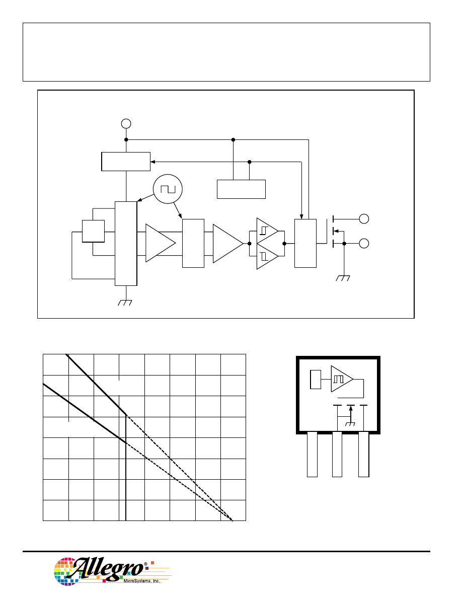
These devices include on a single silicon chip a Hall-voltage generator,
small-signal amplifier, chopper stabilization, a latch, and a MOSFET output.
Advanced BiCMOS processing is used to take advantage of low-voltage and
low-power requirements, component matching, very low input-offset errors,
and small component geometries.
The A3209Ex and A3210Ex are rated for operation over a temperature
range of -40
°
C to +85
°
C. Two package styles provide a magnetically opti-
mized package for most applications. Suffix ‘LH’ is a miniature low-profile
surface-mount package while suffix ‘UA’ is a three-lead ultra-mini-SIP for
through-hole or surface mounting.
FEATURES
■ Micropower Operation
■ Operate With North or South Pole
■ 2.5 V to 3.5 V Battery Operation
■ Chopper Stabilized
Superior Temperature Stability
Extremely Low Switch-Point Drift
Insensitive to Physical Stress
■ ESD Protected to 5 kV
■ Solid-State Reliability
■ Small Size
■ Easily Manufacturable With Magnet Pole Independence
Data Sheet
27622.60A‡
Always order by complete part number: the prefix ‘A’ + the basic four-digit
part number + the suffix ‘E’ to indicate operating temperature range + a
suffix to indicate package style, e.g., A3210ELH .
Package Suffix ‘LH’ Pinning
(SOT23W)
3209
AND
3210
ABSOLUTE MAXIMUM RATINGS
at T
A
= +25
°
C
Supply Voltage, V
DD
............................. 5 V
Magnetic Flux Density, B .......... Unlimited
Output Off Voltage, V
OUT
..................... 5 V
Output Current, I
OUT
.......................... 1 mA
Junction Temperature, T
J
............... +170
°
C
Operating Temperature Range,
T
A
............................... -40
°
C to +85
°
C
Storage Temperature Range,
T
S
.............................. -65
°
C to +170
°
C
Caution: These CMOS devices have input
static protection (Class 3) but are still
susceptible to damage if exposed to
extremely high static electrical charges.
Pinning is shown viewed from branded side.
MICROPOWER, ULTRA-SENSITIVE
HALL-EFFECT SWITCHES
X
Dwg. PH-016-1
SUPPLY
GROUND
OUTPUT
V
DD
1
2
3
3209
AND
3210
MICROPOWER,
ULTRA-SENSITIVE
HALL-EFFECT SWITCHES
115 Northeast Cutoff, Box 15036
Worcester, Massachusetts 01615-0036 (508) 853-5000
2
FUNCTIONAL BLOCK DIAGRAM
Copyright © 2000, 2002 Allegro MicroSystems, Inc.
Package Suffix ‘UA’ Pinning
(ultra-mini SIP)
TIMING
LOGIC
Dwg. FH-020-5
LATCH
GROUND
OUTPUT
SUPPLY
X
DYNAMIC
OFFSET CANCELLATION
SWITCH
SAMPLE
& HOLD
Dwg. PH-016
1
SUPPLY
V
DD
GROUND
3
2
OUTPUT
X
Pinning is shown viewed from branded side.
600
400
200
20
60
100
140
0
AMBIENT TEMPERATURE in
°°°°
C
ALLOWABLE PACKAGE POWER DISSIPATION in MILLIWATTS
Dwg. GH-046-3B
Suffix "UA"
R
θ
JA
= 165
°
C/W
40
80
120
180
700
500
300
100
160
Suffix "LH"
R
θ
JA
= 228
°
C/W
800

3209
AND
3210
MICROPOWER,
ULTRA-SENSITIVE
HALL-EFFECT SWITCHES
www.allegromicro.com
3
ELECTRICAL CHARACTERISTICS with C
BYPASS
= 0.1
µ
F,
over operating voltage and temperature range (unless otherwise specified).
Limits
Characteristic
Symbol
Test Conditions
Min.
Typ.
Max.
Units
Operate Points
B
OPS
South pole to branded side
–
30
60
G
B
OPN
North pole to branded side
-60
-35
–
G
Release Points
B
RPS
South pole to branded side
5.0
22
–
G
B
RPN
North pole to branded side
–
-27
-5.0
G
Hysteresis
B
hys
|B
OPx
- B
RPx
|
–
7.7
–
G
NOTES: 1. As used here, negative flux densities are defined as less than zero (algebraic convention) and -50 G is less than +10 G.
2. Typical Data is at T
A
= +25
°
C and V
DD
= 2.75 V and is for design information only.
MAGNETIC CHARACTERISTICS with C
BYPASS
= 0.1
µ
F,
over operating voltage and temperature range (unless otherwise specified).
Limits
Characteristic
Symbol
Test Conditions
Min.
Typ.
Max.
Units
Supply Voltage Range
V
DD
Operating
1)
2.5
2.75
3.5
V
Output Leakage Current
I
OFF
V
OUT
= 3.5 V, B
RPN
< B < B
RPS
–
«1.0
1.0
µ
A
Output On Voltage
V
OUT
I
OUT
= 1 mA, V
DD
= 2.5 V
–
105
300
mV
Awake Time
t
awake
30
60
90
µ
s
Period
t
period
A3209Ex
240
480
720
µ
s
A3210Ex
30
60
90
ms
Duty Cycle
d.c.
A3209Ex
–
12.5
–
%
A3210Ex
–
0.10
–
%
Chopping Frequency
f
C
–
340
–
kHz
Supply Current
I
DD(EN)
Chip awake (enabled)
0.1
–
3.0
mA
(2.5
≤
V
DD
≤
3.5 V)
I
DD(DIS)
Chip asleep (disabled)
1.0
10
50
µ
A
I
DD(AVG)
A3209Ex, V
DD
= 2.75 V
–
145
425
µ
A
A3209Ex, V
DD
= 3.5 V
–
195
425
µ
A
A3210Ex, V
DD
= 2.75 V
–
8.8
25
µ
A
A3210Ex, V
DD
= 3.5 V
–
13
60
µ
A
NOTES: 1. Operate and release points will vary with supply voltage.
2. B
OPx
= operate point (output turns ON); B
RPx
= release point (output turns OFF).
3. Typical Data is at T
A
= +25
°
C and V
DD
= 2.75 V and is for design information only.
3209
AND
3210
MICROPOWER,
ULTRA-SENSITIVE
HALL-EFFECT SWITCHES
115 Northeast Cutoff, Box 15036
Worcester, Massachusetts 01615-0036 (508) 853-5000
4
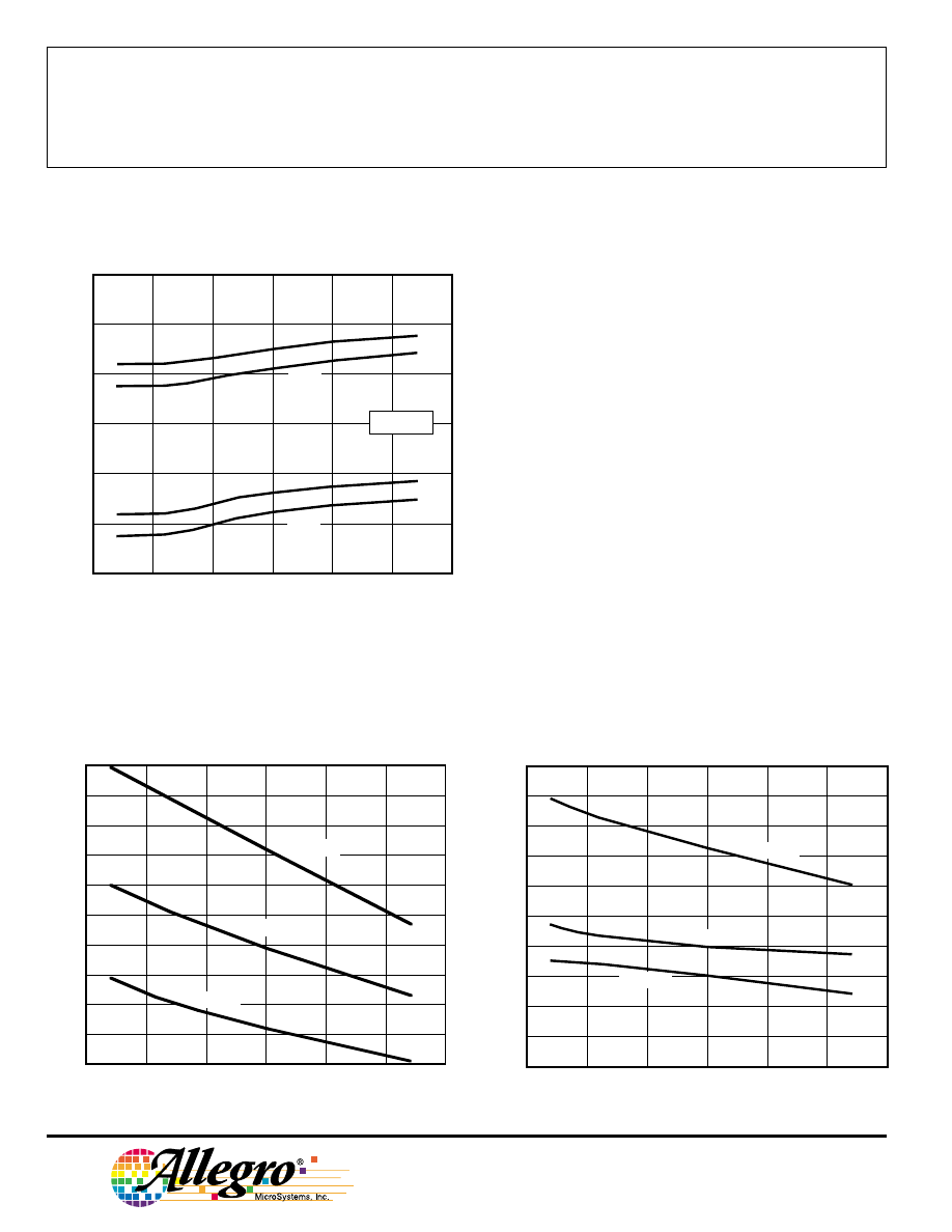
TYPICAL OPERATING CHARACTERISTICS
as a function of temperature
A3210-- SUPPLY CURRENT
SWITCH POINTS
60
SWITCH POINTS IN GAUSS
20
0
-20
-40
0
25
50
75
100
AMBIENT TEMPERATURE IN
°°°°
C
-50
Dwg. GH-027-2
-25
B
OPS
-60
40
B
RPS
B
RPN
B
OPN
V
DD
= 2.75 V
16
AVERAGE SUPPLY CURRENT IN
µµµµ
A
12
10
8.0
6.0
0
25
50
75
100
AMBIENT TEMPERATURE IN
°°°°
C
-50
Dwg. GH-028-6
-25
V
DD
= 3.5 V
V
DD
= 2.5 V
14
V
DD
= 3 V
A3209-- SUPPLY CURRENT
220
AVERAGE SUPPLY CURRENT IN
µµµµ
A
180
160
140
120
0
25
50
75
100
AMBIENT TEMPERATURE IN
°°°°
C
-50
Dwg. GH-028-7
-25
V
DD
= 3.5 V
V
DD
= 3 V
200
V
DD
= 2.5 V
3209
AND
3210
MICROPOWER,
ULTRA-SENSITIVE
HALL-EFFECT SWITCHES
www.allegromicro.com
5
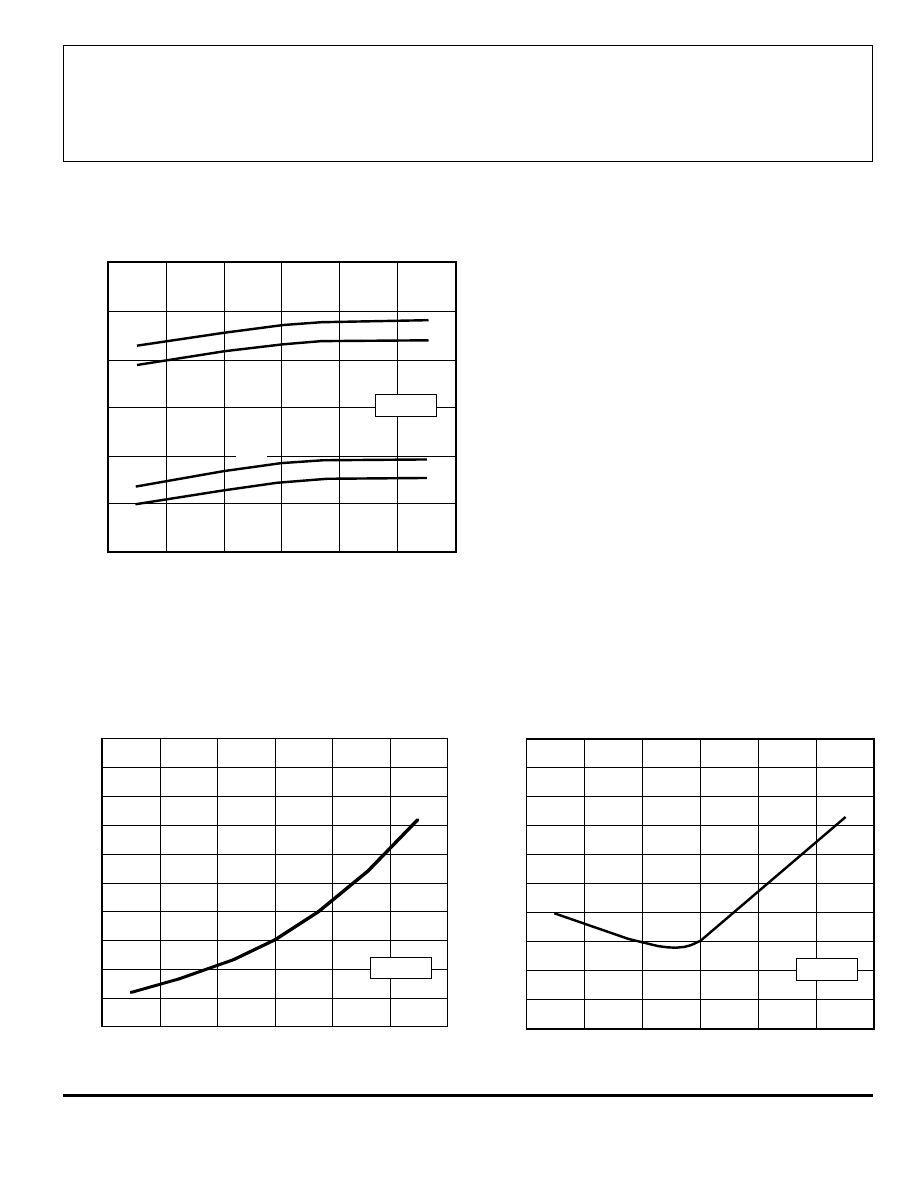
SWITCH POINTS
A3210-- SUPPLY CURRENT
60
SWITCH POINTS IN GAUSS
20
0
-20
-40
2.8
3.0
3.2
3.4
3.6
SUPPLY VOLTAGE IN VOLTS
2.4
Dwg. GH-057-1
2.6
B
OPS
-60
40
B
RPS
B
RPN
B
OPN
T
A
= 25
°
C
16
AVERAGE SUPPLY CURRENT IN
µµµµ
A
12
10
8.0
6.0
2.8
3.0
3.2
3.4
3.6
SUPPLY VOLTAGE IN VOLTS
2.4
Dwg. GH-058-5A
2.6
14
T
A
= 25
°
C
TYPICAL OPERATING CHARACTERISTICS
as a function of supply voltage
A3209-- SUPPLY CURRENT
220
AVERAGE SUPPLY CURRENT IN
µµµµ
A
180
160
140
120
2.8
3.0
3.2
3.4
3.6
SUPPLY VOLTAGE IN VOLTS
2.4
Dwg. GH-058-6
2.6
200
T
A
= 25
°
C
3209
AND
3210
MICROPOWER,
ULTRA-SENSITIVE
HALL-EFFECT SWITCHES
115 Northeast Cutoff, Box 15036
Worcester, Massachusetts 01615-0036 (508) 853-5000
6
All Allegro sensors are subjected to stringent qualification requirements prior to being released to production.
To become qualified, except for the destructive ESD tests, no failures are permitted.
CRITERIA FOR DEVICE QUALIFICATION
Qualification Test
Test Method and Test Conditions
Test Length
Samples
Comments
Biased Humidity (HAST)
T
A
= 130
°
C, RH = 85%
50 hrs
77
V
DD
= V
OUT
= 3 V
High-Temperature
JESD22-A108,
408 hrs
77
V
DD
= V
OUT
= 3 V
Operating Life (HTOL)
T
A
= 150
°
C, T
J
≤
165
°
C
Accelerated HTOL
T
A
= 175
°
C, T
J
≤
190
°
C
504 hrs
77
V
DD
= V
OUT
= 3 V
Autoclave, Unbiased
JESD22-A102, Condition C,
96 hrs
77
T
A
= 121
°
C, 15 psig
High-Temperature
MIL-STD-883, Method 1008,
1000 hrs
77
(Bake) Storage Life
T
A
= 170
°
C
Temperature Cycle
MIL-STD-883, Method 1010,
500 cycles
77
-65
°
C to +150
°
C
Latch-Up
—
Pre/Post
6
Reading
Electro-Thermally
—
Pre/Post
6
Induced Gate Leakage
Reading
ESD,
CDF-AEC-Q100-002
Pre/Post
3 per
Test to failure,
Human Body Model
Reading
test
All leads > 5 kV
ESD,
JESD22-A115
Pre/Post
3 per
Test to failure,
Machine Model
Reading
test
All leads > 350 V
Electrical Distributions
Per Specification
—
30
3209
AND
3210
MICROPOWER,
ULTRA-SENSITIVE
HALL-EFFECT SWITCHES
www.allegromicro.com
7
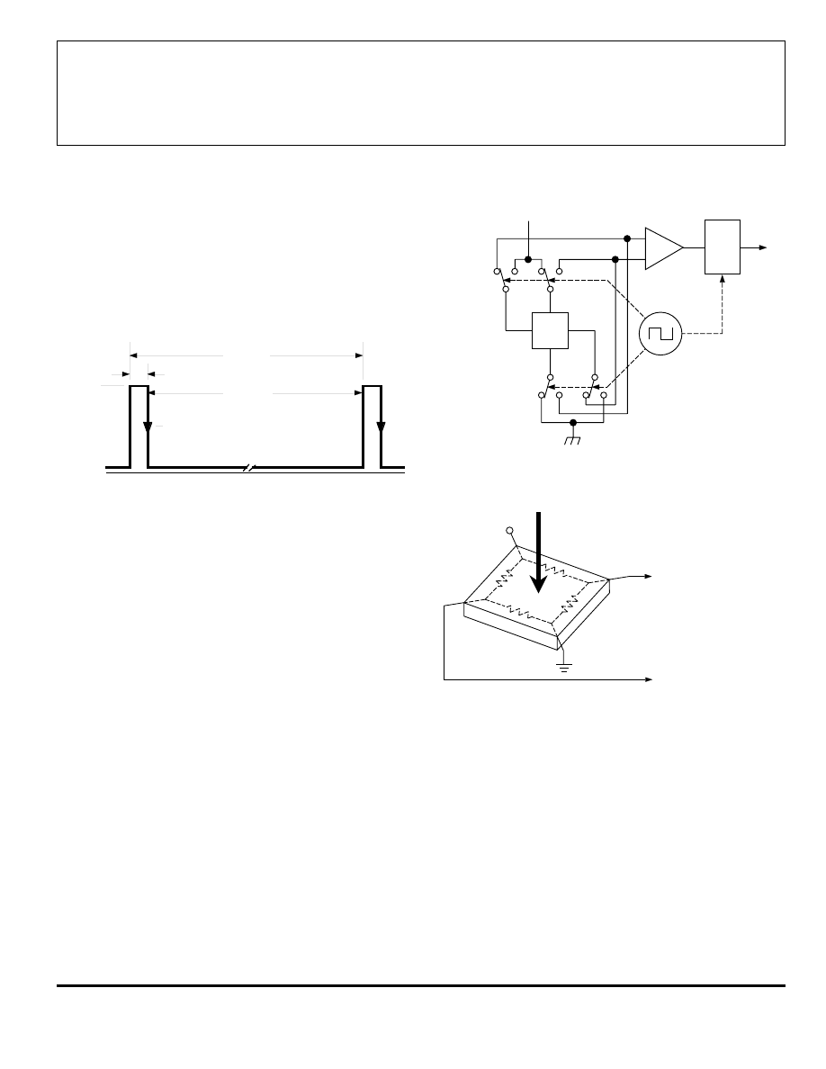
FUNCTIONAL DESCRIPTION
Low Average Power. Internal timing circuitry activates the
sensor for 60
µ
s and deactivates it for the remainder of the
period (480
µ
s for the A3209Ex and 60 ms for the A3210Ex).
A short "awake" time allows for stabilization prior to the sensor
sampling and data latching on the falling edge of the timing
pulse. The output during the "sleep" time is latched in the last
sampled state. The supply current is not affected by the output
state.
Chopper-Stabilized Technique. The Hall element can be
considered as a resistor array similar to a Wheatstone bridge. A
large portion of the offset is a result of the mismatching of these
resistors. These devices use a proprietary dynamic offset
cancellation technique, with an internal high-frequency clock to
reduce the residual offset voltage of the Hall element that is
normally caused by device overmolding, temperature dependen-
cies, and thermal stress. The chopper-stabilizing technique
cancels the mismatching of the resistor circuit by changing the
direction of the current flowing through the Hall plate using
CMOS switches and Hall voltage measurement taps, while
maintaing the Hall-voltage signal that is induced by the external
magnetic flux. The signal is then captured by a sample-and-
hold circuit and further processed using low-offset bipolar
circuitry. This technique produces devices that have an
extremely stable quiescent Hall output voltage, are immune to
thermal stress, and have precise recoverability after temperature
cycling. This technique will also slightly degrade the device
output repeatability. A relatively high sampling frequency is
used in order that faster signals can be processed.
More detailed descriptions of the circuit operation can be
found in: Technical Paper STP 97-10, Monolithic Magnetic
Hall Sensor Using Dynamic Quadrature Offset Cancellation
and Technical Paper STP 99-1, Chopper-Stabilized Amplifiers
With A Track-and-Hold Signal Demodulator.
Dwg. WH-017-1
0
PERIOD
60
µ
s - "AWAKE"
"SLEEP"
I
DD(EN)
I
DD(DIS)
SAMPLE &
OUTPUT LATCHED
Dwg. EH-012-1
SAMPLE
& HOLD
X
+V
+V
HALL
VOLTAGE
B
+
—
Dwg. AH-011-2
Operation. The output of this device switches low (turns on)
when a magnetic field perpendicular to the Hall sensor exceeds
the operate point B
OPS
(or is less than B
OPN
). After turn-on, the
output is capable of sinking up to 1 mA and the output voltage
is V
OUT(ON)
. When the magnetic field is reduced below the
release point B
RPS
(or increased above B
RPN
), the device output
switches high (turns off). The difference in the magnetic
operate and release points is the hysteresis (B
hys
) of the device.
This built-in hysteresis allows clean switching of the output
even in the presence of external mechanical vibration and
electrical noise.
As used here, negative flux densities are defined as less
than zero (algebraic convention) and -50 G is less than +10 G.
3209
AND
3210
MICROPOWER,
ULTRA-SENSITIVE
HALL-EFFECT SWITCHES
115 Northeast Cutoff, Box 15036
Worcester, Massachusetts 01615-0036 (508) 853-5000
8
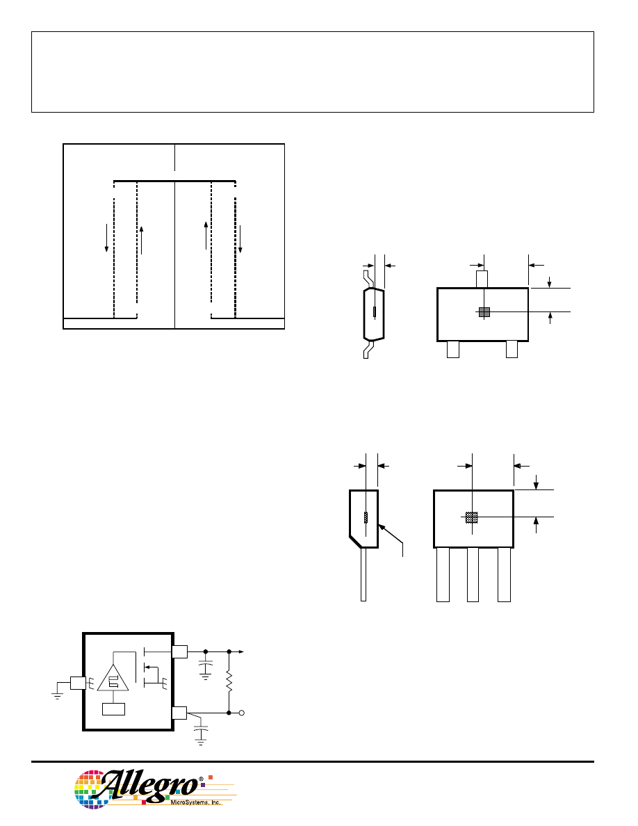
SENSOR LOCATIONS
(
±
0.005” [0.13 mm] die placement)
Package Designator ‘LH’
Package Designators ‘UA’, UA-LC', and ‘UA-TL’
Although sensor location is accurate to three sigma for a
particular design, product improvements may result in small
changes to sensor location.
OUTPUT
Dwg. EH-013-2
0.1
µ
F
SUPPLY
(3 V BATTERY)
10 pF
50 k
Ω
X
V
DD
1
2
3
1
3
2
Dwg. MH-011-11A
0.0195"
0.50 mm
NOM
BRANDED
SURFACE
ACTIVE AREA DEPTH
0.081"
2.06 mm
0.057"
1.45 mm
A
0.038"
0.96 mm
1
2
Dwg. MH-025
0.011"
0.28 mm
NOM
ACTIVE AREA DEPTH
0.059"
1.49 mm
A
3
Allegro
Applications. Allegro's pole-independent sensing technique
allows for operation with either a north pole or south pole
magnet orientation, enhancing the manufacturability of the
device. The state-of-the-art technology provides the same
output polarity for either pole face.
It is strongly recommended that an external bypass capaci-
tor be connected (in close proximity to the Hall sensor) between
the supply and ground of the device to reduce both external
noise and noise generated by the chopper-stabilization tech-
nique. This is especially true due to the relatively high imped-
ance of battery supplies.
The simplest form of magnet that will operate these devices
is a bar magnet with either pole near the branded surface of the
device. Many other methods of operation are possible. Exten-
sive applications information on magnets and Hall-effect
sensors is also available in the Allegro Electronic Data Book
AMS-702 or Application Note 27701, or at
www.allegromicro.com
0
+B
0
Dwg. GH-043-1
-B
OUTPUT ON
5 V
MAX
BOPS
BRPS
B OPN
BRPN
OUTPUT VOLTAGE
MAGNETIC FLUX
OUTPUT OFF
3209
AND
3210
MICROPOWER,
ULTRA-SENSITIVE
HALL-EFFECT SWITCHES
www.allegromicro.com
9
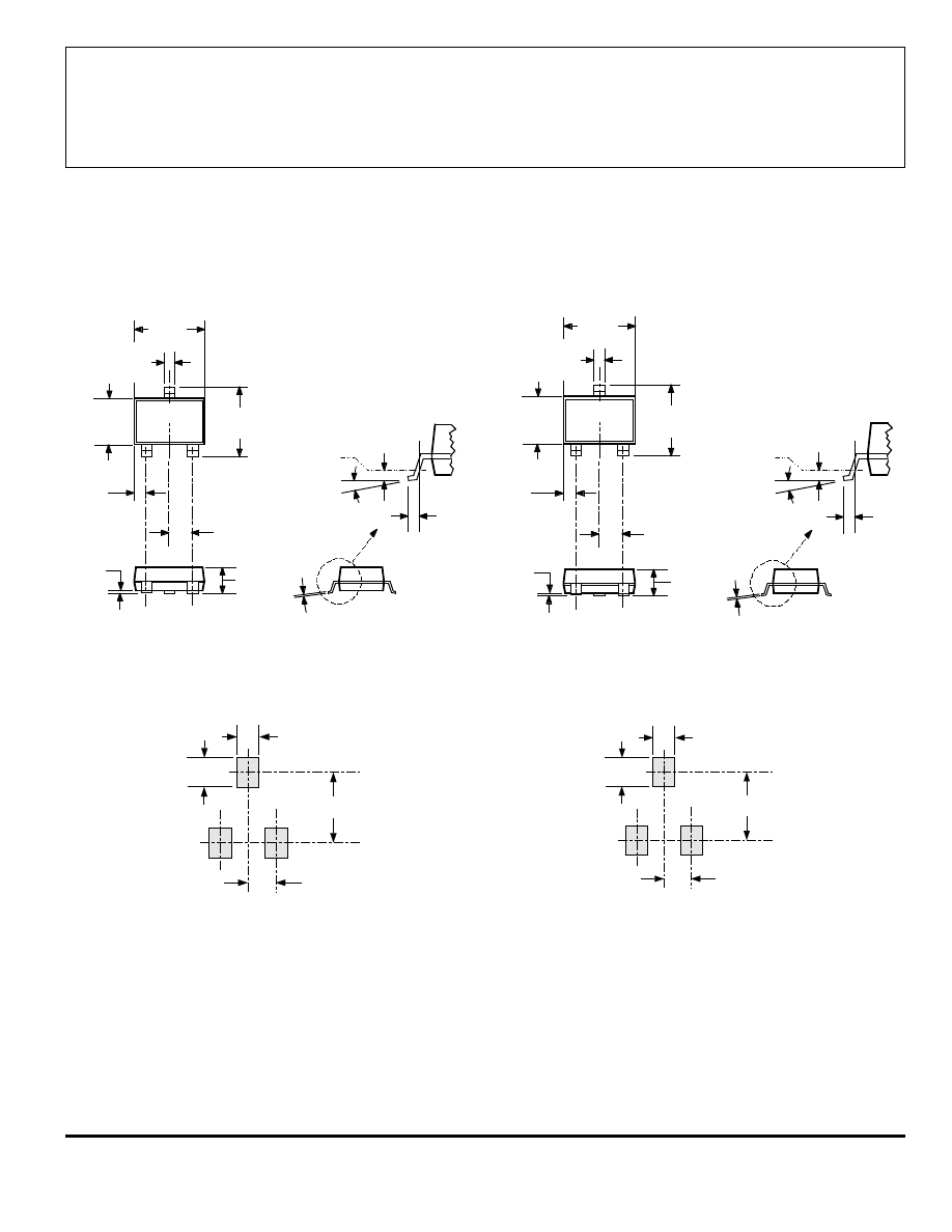
PACKAGE DESIGNATOR ‘LH’
(fits SC-74A solder-pad layout)
NOTES: 1.
Tolerances on package height and width represent allowable mold offsets. Dimensions given are
measured at the widest point (parting line).
2.
Exact body and lead configuration at vendor’s option within limits shown.
3.
Height does not include mold gate flash.
4.
Where no tolerance is specified, dimension is nominal.
Dimensions in Inches
(for reference only)
Dimensions in Millimeters
(controlling dimensions)
Dwg. MA-011-3 in
1
2
0.039
0.094
0.037
0.028
3
Dwg. MA-011-3 mm
1
2
1.00
2.40
0.95
0.70
3
Dwg. MA-010-3C in
1
2
0.006
0.000
0.0079
0.0050
0.083
0.073
0.118
0.106
0.037
BSC
0.022
REF
0.020
0.012
3
0.045
0.032
0
°
TO
8
°
0.020
MIN
GAUGE PLANE
SEATING PLANE
0.020
BSC
0.122
0.114
Dwg. MA-010-3C mm
1
2
0.15
0.00
0.20
0.127
2.10
1.85
3.00
2.70
0.95
BSC
0.55
REF
0.50
0.30
3
1.13
0.87
0
°
TO
8
°
0.25
MIN
GAUGE PLANE
SEATING PLANE
0.25
BSC
3.10
2.90
3209
AND
3210
MICROPOWER,
ULTRA-SENSITIVE
HALL-EFFECT SWITCHES
115 Northeast Cutoff, Box 15036
Worcester, Massachusetts 01615-0036 (508) 853-5000
10
Dimensions in Inches
(controlling dimensions)
Dimensions in Millimeters
(for reference only)
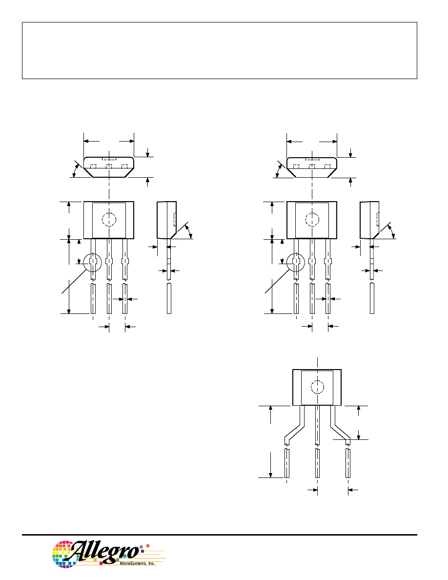
PACKAGE DESIGNATOR ‘UA’
NOTES: 1.
Tolerances on package height and width represent
allowable mold offsets. Dimensions given are
measured at the widest point (parting line).
2.
Exact body and lead configuration at vendor’s option
within limits shown.
3.
Height does not include mold gate flash.
4.
Recommended minimum PWB hole diameter to clear
transition area is 0.035" (0.89 mm).
5.
Where no tolerance is specified, dimension is nominal.
6.
Supplied in bulk pack (500 pieces per bag).
Dwg. MH-014E in
0.164
0.159
0.062
0.058
0.0173
0.0138
0.050
BSC
45
°
0.640
0.600
0.0189
0.0142
0.085
MAX
45
°
0.031
1
2
3
0.122
0.117
SEE NOTE
Dwg. MH-014E mm
4.17
4.04
1.57
1.47
0.44
0.35
1.27
BSC
45
°
16.26
15.24
0.48
0.36
2.16
MAX
45
°
0.79
1
2
3
3.10
2.97
SEE NOTE
Radial Lead Form (order A32xxEUA-LC)
NOTE:
Lead-form dimensions are the nominals produced on the
forming equipment. No dimensional tolerance is implied or
guaranteed for bulk packaging (500 pieces per bag).
0.620"
0.500"
(15.7 mm
12.7 mm)
0.100"
(2.5 mm)
Dwg. MH-026
0.108"
(2.74 mm)
1
2
3

3209
AND
3210
MICROPOWER,
ULTRA-SENSITIVE
HALL-EFFECT SWITCHES
www.allegromicro.com
11
The products described herein are manufactured under one or
more of the following U.S. patents: 5,045,920; 5,264,783; 5,442,283;
5,389,889; 5,581,179; 5,517,112; 5,619,137; 5,621,319; 5,650,719;
5,686,894; 5,694,038; 5,729,130; 5,917,320; and other patents
pending.
Allegro MicroSystems, Inc. reserves the right to make, from time to
time, such departures from the detail specifications as may be
required to permit improvements in the performance, reliability, or
manufacturability of its products. Before placing an order, the user is
cautioned to verify that the information being relied upon is current.
Allegro products are not authorized for use as critical components
in life-support appliances, devices, or systems without express written
approval.
The information included herein is believed to be accurate and
reliable. However, Allegro MicroSystems, Inc. assumes no responsi-
bility for its use; nor for any infringements of patents or other rights of
third parties that may result from its use.
3209
AND
3210
MICROPOWER,
ULTRA-SENSITIVE
HALL-EFFECT SWITCHES
115 Northeast Cutoff, Box 15036
Worcester, Massachusetts 01615-0036 (508) 853-5000
12
HALL-EFFECT SENSORS
UNIPOLAR HALL-EFFECT DIGITAL SWITCHES
Partial
Operate
Release
Hysteresis
Replaces
Part
Point (G)
Point (G)
(G)
Oper.
and
Number
Over Oper. Voltage & Temp. Range
Temp.
Packages
Comments
A3121x
220 to 500
80 to 410
60 to 150
E, L
LT, UA
3019, 3113, 3119
A3122x
260 to 430
120 to 360
70 to 140
E, L
LT, UA
A3123x
230 to 470
160 to 330
70 to 140
E, L
LT, UA
A3141x
30 to 175
10 to 145
20 to 80
E, L
LT, UA
3040, 3140
A3142x
115 to 245
60 to 190
30 to 80
E, L
LT, UA
A3143x
205 to 355
150 to 300
30 to 80
E, L
LT, UA
A3144x
35 to 450
25 to 430
>20
E, L
LT, UA
3020, 3120
A3161E
<160 (Typ 130) >30 (Typ 110)
5 to 80
E
LT, UA
2-wire operation
A3163E
<160 (Typ 98)
>30 (Typ 79)
5 to 40
E
LT, UA
2-wire
A3240x
<50 (Typ 35)
>5 (Typ 25)
Typ 10
E, L
LH, LT, UA
chopper stabilized
A3250x
<50 to >350
_
5 to 35
J, L
UA
programmable, chopper stabilized
A3251x
<50 to >350
_
5 to 35
J, L
UA
programmable, chopper stabilized
A3361E
<125
>40
5 to 30
E
LH, LT, UA
2-wire, chopper stabilized,
output normally high
A3362E
<125
>40
5 to 30
E
LH, LT, UA
2-wire, chopper stabilized,
output normally low
MICROPOWER OMNIPOLAR HALL-EFFECT DIGITAL SWITCHES
Partial
Operate
Release
Hysteresis
Average
Part
Points (G)
Points (G)
(G)
Oper.
Supply
Number
Over Oper. Voltage & Temp. Range
Temp.
Packages
Current (
µ
A)
A3209E
>-60, <60
<-5, >5
Typ 7.7
E
LH, UA
<425 (Typ 145)
A3210E
>-60, <60
<-5, >5
Typ 7.7
E
LH, UA
<60 (Typ 8.8)
A3212E
>-55, <55
<-10, >10
Typ. 8
E
LH, UA
<10 (Typ 4.2)
Wyszukiwarka
Podobne podstrony:
3209
01308214Foto Bigid 3209
3209
3209
3209
Valerie Parv Far From Over [HR 3209, MB 3539] (v0 9) (docx) 2
więcej podobnych podstron