MOTOROLA UK
REDWOOD
CROCKFORD LANE
CHINEHAM BUSINESS PARK
CHINEHAM
BASINGSTOKE
UNITED KINGDOM RG24 8WQ
CSB-1190-3
Country : UK
Date : 2/2/2007
APC : G26
Repair Level : 3
Title
M702iGM702iSMOTORAZR V3xx - 3G - Atlas_Switcher
Model Effected
Izar_Japan, Izar_Global, Izar_Global i-mode and Scorpius
PROBLEM
Problem Description
a. Description
In M702iS and M702iG, we use Switch-Mode supplies topology in powering our Baseband Processor (Argon IC) and Memory IC. The
switcher supplies is integrated into our Power Management IC, namely, ATLAS IC.
It was found that a small percentage of the ATLAS IC has instable switchers such that when the Switcher supplies goes into low power
mode (PFM mode), the switcher supplies voltage goes out of regulation and the voltage of the supplies drop significantly below the
intended voltage and caused undesirable behavior in the phone.
b. Symptoms Observed
When this issue occurred, the phone will panic and reset itself. On some cases, it will appear as white screen on the display. Most of
the time, the issues occurs within minutes when the phone power up.
c. How to Duplicate Symptoms
Unit can be subject to “Powering Up” diagnostic test to determine whether units reset repeatedly after powering up or frozen up without
any ability to response to any key presses.
Root Cause
Freescale root caused the problem to an implementation of trim algorithm in the final test. Most of the ATLAS parts don’t need any
trimming for proper operation of the switcher in the PFM mode, however in a very small percentage of the parts, ATLAS needs to be
trimmed so that the switcher voltage in the PFM mode does not droop.
During load regulation test if the device goes out of regulation, there is a trim bit available inside the IC to correct for offsets. Correct
fuse blowing will bring the part back into regulation.
However, on small percentage of parts prior to date code 0645, the fuse was not blown correctly due to an inappropriate application of
a tester power supply to a capacitor used to blow the fuses. This resulted in potentially not enough energy being provided for fuse
blowing and incomplete opening of the fuse.
After trimming, the switcher is loaded with 50mA in PFM mode which is approximately 50x higher current load than that pulled by Argon
in the application. The 50x higher current is used to provide significant guard-band to fail marginal devices which would be fully
functional in the phone
SOLUTION
Containment Actions
a. Actions Taken
1) The ATLAS IC vendor, Freescale was notified and corrected the problem in their Factory ATE test.
2) Freescale communicated to Motorola that any Atlas part with date code 0645 or newer will not have this issue.
3) Motorola informed Flextronics factory to purge out all the bad datecode parts on 12/28/06
4) Motorola informed Flextronics factory on 12/28/06 to use only 0645 or newer datecode for M702iS and M702iG phone.
5) Flextronics will send all Atlas parts prior to 0645 to Freescale for re-screening.
6) Motorola implemented ATLAS screening to catch all ATLAS IC with this failure.
b. Verification of Containment Actions
1) Freescale ATE implementation was verified further by EVB level testing
2) Freescale tested 10,000 raw stock parts, 7 hard failures with identical characteristics to the field return were observed. However, the
theoretical upper limit for this failure could be as high as 0.8% if we assume that all the parts which should have been trimmed didn
trimmed.
3) Motorola tested the ATLAS screening on Customer Field Return unit and the test results were in good agreement with the actual
bench test results. This ensure the integrity of the ATLAS screening test.
Page 1 of 5
04/04/2007
https://md-service-tmp.motorola.com/CSB_Preview.aspx?member_of=MjcYeOuw2I...
4) The failure rate will be zero with 0645 or newer date code
FIELD SERVICE ACTION
Atlas Switcher Test procedure
1. Confirm phone panics with white screen after it goes into DSM.
2. Confirm phone does not panic when USB cable is plugged in.
3. Monitor switcher LX pins to confirm SW1 or SW2 or both fail in PFM mode, and record Atlas date code.
4. Determine if the device is functional or if it needs to bereplaced.
If the customer complaint is determined not to be related to this issue, then follow normal troubleshooting techniques per the customer
complaint.
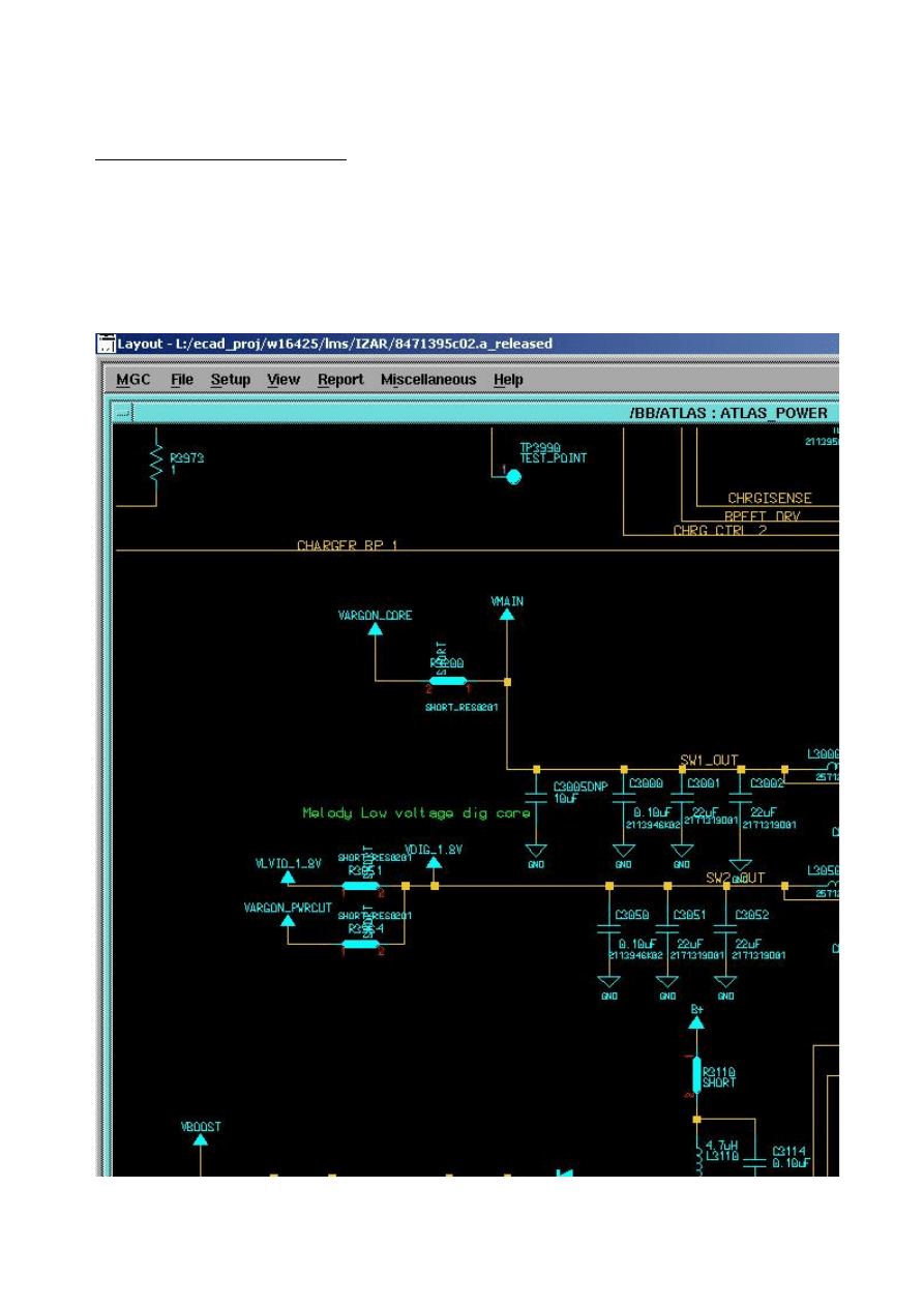
Switcher LX pins in schematic
Good Unit
Page 2 of 5
04/04/2007
https://md-service-tmp.motorola.com/CSB_Preview.aspx?member_of=MjcYeOuw2I...
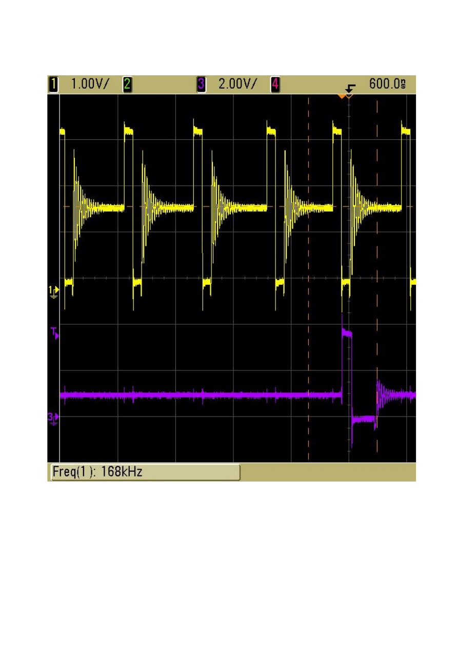
Channel 1: SW1 LX
Channel 2: SW2 LX
When phone goes into DSM, Atlas SW1 and SW2 LX pin switches normally at KHz range in PFM mode.
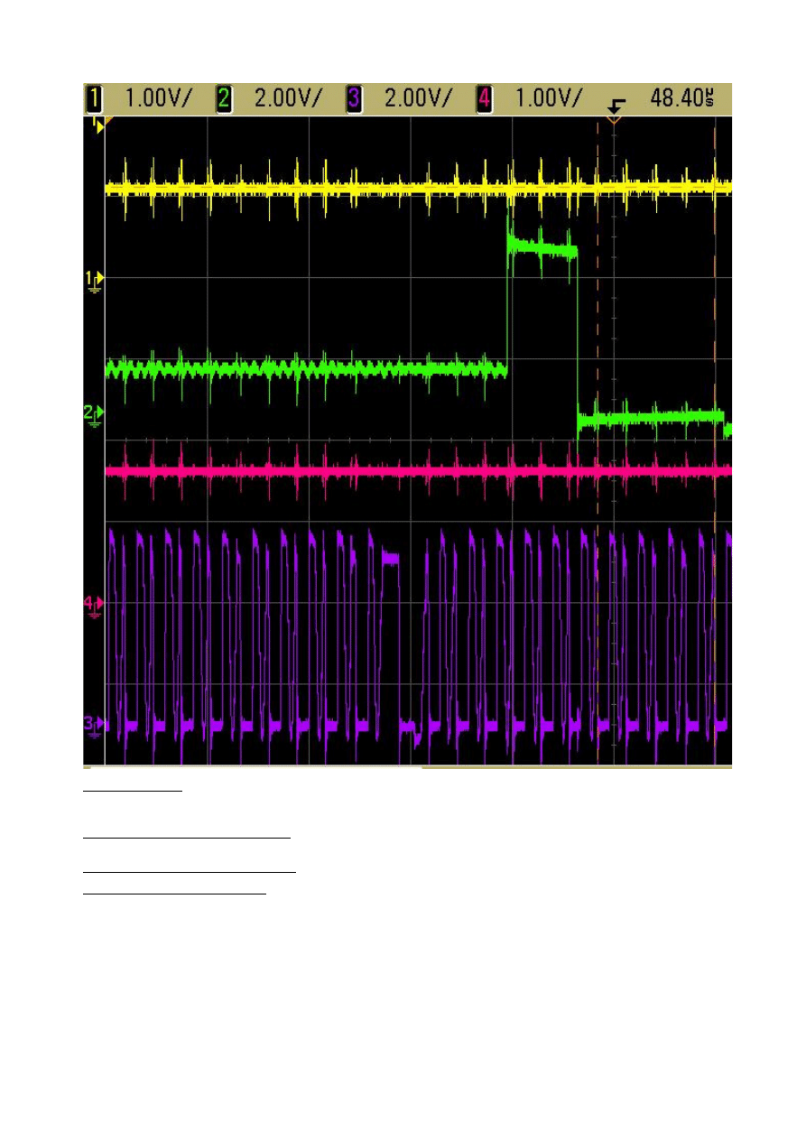
Bad Unit
Channel 1: SW1 output
Channel 2: SW1 LX
Channel 3: SW2 LX
Channel 4: SW2 output
When phone goes into DSM, Atlas SW1 LX pin switches normally at KHz range and SW2 LX pin switches abnormally at MHz range in
PFM mode.
Page 3 of 5
04/04/2007
https://md-service-tmp.motorola.com/CSB_Preview.aspx?member_of=MjcYeOuw2I...
Service Inventory
CALL CENTER ACTION
When responding to customer inquiries on this complaint, please direct the customers to have their phones serviced as per this FSB.
SERVICE ENTRY CODE
Global Service Codes
Complaint Code:
DIM01 - Display Main - No display
TON03 - Turn on/off - Auto power down in standby
Problem Found Code: DIS01 - Display Secondary - No display
TON03 - Turn on/off - Auto power down in standby
Reference Designator:U - Integrated Circuit And
Repair Code:
RTH02 - Replace Level 3 part - CSB/FSB
Page 4 of 5
04/04/2007
https://md-service-tmp.motorola.com/CSB_Preview.aspx?member_of=MjcYeOuw2I...

If applicable, note this bulletin number on warranty claim forms and make necessary changes to service manuals.2007-31
© Copyright 2007 Motorola Inc. All Rights Reserved.
Close
|
Page 5 of 5
04/04/2007
https://md-service-tmp.motorola.com/CSB_Preview.aspx?member_of=MjcYeOuw2I...
Wyszukiwarka
Podobne podstrony:
CSB 1018 3 Static audio failure
93 1343 1362 Tool Failures Causes and Prevention
Page153 Model 2491 2492 2493 Digital Switchboard meter c
Baumer Inductive proximity switch IFFM 08P17A6 KS35L
BODY SWITCH
5 3 3 5 Packet Tracer Configure Layer 3 Switches Instructions
easy500 Year time switch HLP EN
07 Rynek korzysci i koszty (market failures) government failures Nadwyzka konsumenta i producenta
1830 switch datasheet
2011 4 JUL Organ Failure in Critical Illness
MikroTik jako zarządzany switch
Instrukcja SWITCH
61 STEERING COLUMN SWITCHES
0 0 0 1 Lab Initializing and Reloading a Router and Switch
Cisco 1900 Catalyst Switch Commands
Inventor2011 Classic UI Switch
[2006] Application of Magnetic Energy Recovery Switch (MERS) to Improve Output Power of Wind Turbine
Instrukcja SWITCH2
więcej podobnych podstron