WHEEL ALIGNMENT SPECIFICATIONS & PROCEDURES
1993 Mitsubishi Montero
1993 WHEEL ALIGNMENT
Mitsubishi - Specifications & Procedures
Montero
NOTE: Prior to performing wheel alignment, perform preliminary
visual and mechanical inspection of wheels, tires and
suspension components. See PRE-ALIGNMENT INSTRUCTIONS in
WHEEL ALIGNMENT THEORY/OPERATION article in GENERAL
INFORMATION section.
WHEEL ALIGNMENT PROCEDURES
CAMBER ADJUSTMENT
1) Check camber. See appropriate WHEEL ALIGNMENT
SPECIFICATIONS table. If camber is not within specification, remove
shock absorber mounting nut and lock nut.
CAUTION: Difference in shim thickness between front and rear must
not exceed .16" (4.0 mm). DO NOT use more than 3 shims at
one location.
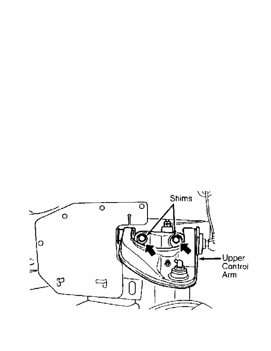
2) Compress shock absorber, and loosen upper arm mounting
bolts and nuts. Adjust camber by increasing or decreasing shims
between upper arm shaft and crossmember. See Fig. 1.
Fig. 1: Adjusting Camber & Caster (Typical)
Courtesy of Mitsubishi Motor Sales of America.
CASTER ADJUSTMENT

Check caster. See appropriate WHEEL ALIGNMENT SPECIFICATIONS
table. If caster is not within specification, replace damaged or bent
parts.
TOE-IN ADJUSTMENT
Front
Check front toe-in. See appropriate WHEEL ALIGNMENT
SPECIFICATIONS table. If front toe-in is not within specification,
remove clips. Turn tie rods or turnbuckles same amount, but in
opposite directions. Recheck front toe-in.
Rear
Check rear toe-in. See appropriate WHEEL ALIGNMENT
SPECIFICATIONS table. If rear toe-in is not within specification,
replace damaged or bent parts.
TORQUE SPECIFICATIONS
TORQUE SPECIFICATIONS TABLE
Application Ft. Lbs. (N.m)
Shock Absorber-To-Crossmember Nut .......... 10-13 (14-18)
Shock Absorber-To-Lower Arm Bolt ........... 11-16 (15-22)
Upper Arm Shaft To Crossmember ............ 72-87 (98-118)
Wheel Lug Nut ............................. 72-87 (98-118)
WHEEL ALIGNMENT SPECIFICATIONS
WHEEL ALIGNMENT SPECIFICATIONS TABLE
Application Preferred Range
Camber (1)
Front .................. 0.67 ............ 0.17 To 1.17
Rear ..................... 0 .................... .....
Caster (1) ................ 3 ................... 2 To 4
Toe-In (1)
Front .................. 0.28 ............... 0 To 0.56
Rear ..................... 0 .................... .....
Toe-In (2)
Front ................ 0.14 (3.5) ... 0 To 0.28 (0 To 7)
Rear ...................... 0 .................... .....
Toe-Out On Turns (1)
Inner .................. 21.93 .................. .....
Outer ................... 20 .................... .....
(1) - Measurement in degrees.
(2) - Measurement in inches (mm).
Wyszukiwarka
Podobne podstrony:
74 WHEEL ALIGNMENT SPECIFICATIONS & PROCEDURES
03 Wheel Alignment Procedures
Electronics 4 Systems and procedures S
Flavon Policies and Procedures 20120611
75 WHEEL ALIGNMENT THEORY OPERATION
duties and procedures
M32b Wheel Alignment
Sampling?sign and Procedures
Chapter 3 Definitions and Procedures
Sampling?sign and Procedures
Definitions of a method, procedure, approach,?sign and procedure
Electronics 4 Systems and procedures S
Using Verification Technology to Specify and Detect Malware
wheel alignment theory operation
(ebook pdf) programming primer for object oriented and procedural programming in java, c, c
Specification and evaluation of polymorphic shellcode properties using a new temporal logic
więcej podobnych podstron