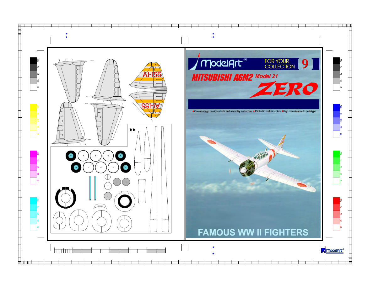
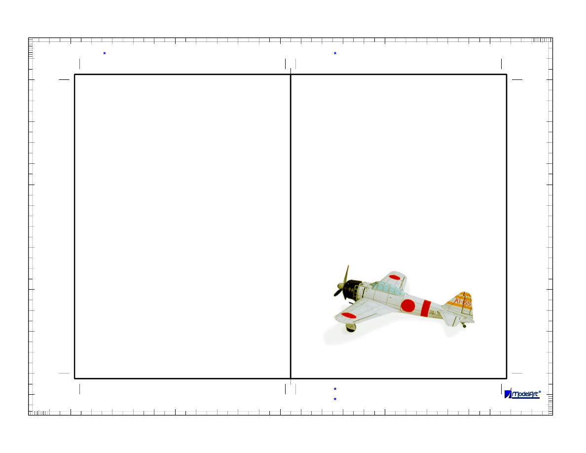
A6M2 ZERO Model 21
At the time of its appearance the Zero
performances were far superior to any
existing fighter in the world. This was the
most important factor for the Japanese
fateful decision of attacking the United
States. This model represents the leader of
the fighter escort of the 1
, Pearl
Harbor, Dec. 8, 1941.
Koku Sentai
© 1998 E. Zarkov
Glue these parts on
0.35 mm card
scale
PRECISE CARD MODEL
1/72
1d
1c
1b
1a
1
4b
4c
5b
6b
8a
16b
16c
11b
11c
17c
17b
18b
23
23a
24
24a
25
25a
29
29a
29b
29a
29
34
10
10
10
20
20
30
30
40
40
50
50
60
60
70
70
80
80
90
90
100
100
110
110
120
120
130
130
140
140
150
150
160
160
170
170
10
20
20
30
30
40
40
50
50
60
60
70
70
80
80
90
90
100
100
110
110
120
120
130
130
140
140
150
150
160
160
170
170
180
180
190
190
200
200
210
210
220
220
230
230
240
240
Page 1 of 5
1
0
3
4
5
6
2
Scale 1:72
meters
Use border scales to control the dimensions of the printed layout
For individual use only, under no circumstances can this document
You can contact us sending E-mail to: modelart@tusk.icn.bg
Print the layout with maximal available resolution
be resold without written permission by ModelArt.
For best results use 80 gr/m special coated paper If you have ink jet printer
2
For best color matching use color reference tables for printer calibration
27b
28b
A6M2 ZERO Model 21
A6M2 ZERO Model 21
© 1998 E. Zarkov
2
3
4
5
6
7
8
9
10
10b
11
12
13
14
15
16
17
18
19
20 20a
22
21
27
27a
27c
28
28a
28c
27d
28d
30
30a
31a
31
32
33
35
36
37
10
10
10
20
20
30
30
40
40
50
50
60
60
70
70
80
80
90
90
100
100
110
110
120
120
130
130
140
140
150
150
160
160
170
170
10
20
20
30
30
40
40
50
50
60
60
70
70
80
80
90
90
100
100
110
110
120
120
130
130
140
140
150
150
160
160
170
170
180
180
190
190
200
200
210
210
220
220
230
230
240
240
Page 2 of 5
1
0
3
4
5
6
2
Scale 1:72
meters
Use border scales to control the dimensions of the printed layout
For individual use only, under no circumstances can this document
You can contact us sending E-mail to: modelart@tusk.icn.bg
Print the layout with maximal available resolution
be resold without written permission by ModelArt.
For best results use 80 gr/m special coated paper If you have ink jet printer
2
For best color matching use color reference tables for printer calibration
© 1998 E. Zarkov
2, 2a
1c
1, 1b
2b
1d
1a
3a
3
2a
3a
2b
4a
5a
6a
7a
10a
11a
12a
13a
14a
5b 5a 5 4b 4a 4
8 8a
10b 10a 10
4c 6a 6 6b 7a 7
9
10
10
10
20
20
30
30
40
40
50
50
60
60
70
70
80
80
90
90
100
100
110
110
120
120
130
130
140
140
150
150
160
160
170
170
10
20
20
30
30
40
40
50
50
60
60
70
70
80
80
90
90
100
100
110
110
120
120
130
130
140
140
150
150
160
160
170
170
180
180
190
190
200
200
210
210
220
220
230
230
240
240
Page 3 of 5
For individual use only, under no circumstances can this document
You can contact us sending E-mail to: modelart@tusk.icn.bg
Print the layout with maximal available resolution
be resold without written permission by ModelArt.
For best results use 80 gr/m special coated paper If you have ink jet printer
2
ASSEMBLY INSTRUCTION
© 1998 E. Zarkov
A6M2 ZERO Model 21
A6M2 ZERO Model 21
© 1998 E. Zarkov
16a
17a
18a
19a
A6M2 ZERO Model 21
A6M2 ZERO Model 21
10
10
10
20
20
30
30
40
40
50
50
60
60
70
70
80
80
90
90
100
100
110
110
120
120
130
130
140
140
150
150
160
160
170
170
10
20
20
30
30
40
40
50
50
60
60
70
70
80
80
90
90
100
100
110
110
120
120
130
130
140
140
150
150
160
160
170
170
180
180
190
190
200
200
210
210
220
220
230
230
240
240
Page 4 of 5
For individual use only, under no circumstances can this document
You can contact us sending E-mail to: modelart@tusk.icn.bg
Print the layout with maximal available resolution
be resold without written permission by ModelArt.
For best results use 80 gr/m special coated paper If you have ink jet printer
2
ASSEMBLY INSTRUCTION
ASSEMBLY INSTRUCTION
© 1998 E. Zarkov
© 1998 E. Zarkov
19,19a 18a,18b 18 20,20a
pin 17b 17a 17 17c 16b
16a 16 16c 16d
14 14a 13,13a 12a 12
11b 11a 11 15 11c
C D 35 21
34 A B 22
25, 25a
24, 24a
23, 23a
36
37
32
33
28d 28-28c 29-29b 30,30a 31,31a 29-29b 27-27c 27d
E
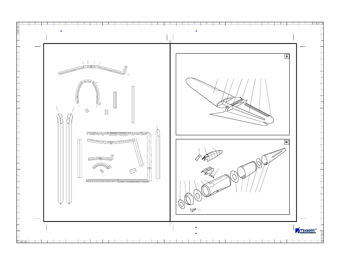
Study the drawings of assembly steps carefully before starting the work on
the model. Make sure you understand the purpose and place of every
part.
The assembly requires some basic tools, such as scissors, sharp
modeling knife, blunt knife for scoring the fold lines, ruler and needle.
Additional materials you need are one pin tomaketheairscrew'sshaft and
one piece of cardboard approx. 0.3 mm thick for reinforcing elements and
wheels. You'll need of course suitable cement too. For cement application
you can use toothpicks or some similar tool (special fine cement applicator
is most suitable if you have one).
First of all you must score with the blunt knife all fold lines shown on the
cutouts with short thin line marks near the parts. To avoid mistakes and
lost parts cut the necessary details shortly before their use. The places
where an additional cutting is needed are marked with small thick line
marks.
Start with the wing. Assemble the central longerone 1-1b and glue the
profiles 1c and 1d to it. Cover the obtained superstructure with the wing’s
halves 2 and 3, assuring straight edges and avoiding wrapping.
Continue with the fuselage part 4. Bend it in oval form and glue it with
connecting stripes 4a. Insert the formers 4b and 4c. Don’t forget to cut the
hole where the wing’s longerone will be placed. Assemble in the same
way parts 5-7. Form and glue the machine guns’ cowling 8 and its former
8a to 4. Carefully form and assemble the cockpit 10-10b and glue it to the
fuselage.
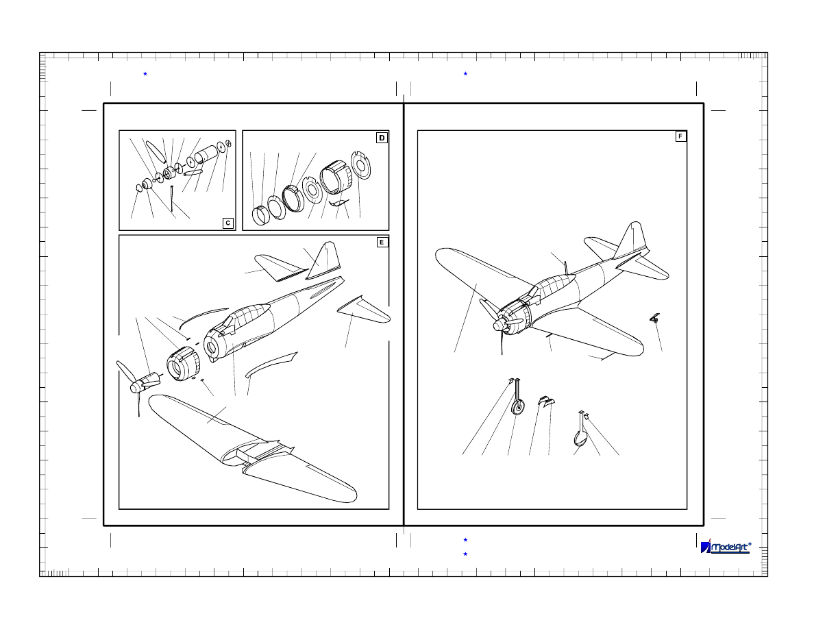
Now focus your attention to the engine cowling. Its assembling is a tricky
work, but if you are careful enough, you can achieve excellent results.
Form and glue the part 11 as shown on view D of the instruction drawings.
Glue the formers 11b and then 11c. 11c must be placed 3mm inside the
rear end of 11. Check thefitting of 11 to fuselage part 5 before drying of the
glue. Add the parts 12 and 13. The front edge of 13 must be formed in
exact circle shape. Insert there 14. Paint the back side of the air intake 15
in black and glue it to the down side of the engine cowling.
Now assemble the propeller and its shaft bearing /parts 16 - 20/ as shown
on view C. The propellermustbecapabletorotatefreely.
A6M2 ZERO Model 21
A6M2 ZERO Model 21
ASSEMBLY INSTRUCTION
10
10
10
20
20
30
30
40
40
50
50
60
60
70
70
80
80
90
90
100
100
110
110
120
120
130
130
140
140
150
150
160
160
170
170
10
20
20
30
30
40
40
50
50
60
60
70
70
80
80
90
90
100
100
110
110
120
120
130
130
140
140
150
150
160
160
170
170
180
180
190
190
200
200
210
210
220
220
230
230
240
240
Page 5 of 5
For individual use only, under no circumstances can this document
You can contact us sending E-mail to: modelart@tusk.icn.bg
Print the layout with maximal available resolution
be resold without written permission by ModelArt.
For best results use 80 gr/m special coated paper If you have ink jet printer
2
Glue the wing to the fuselage. Prepare the aerodynamic wing-fuselage
joints 21 and 22, cutting them approximately to their middle line on
continuation of the line marks outside the parts before forming them in
double curved surfaces. After several dry tests glue them on their places. It
is recommended to apply the glue not on them, but on their attachment
points on the wing and fuselage.
Assemble and glue the vertical and horizontal stabilizers 23, 24 and 25 to
the tail.
Assemble the landing gear. Cut the wheels parts 29 - 29b from thick card
and cement them together. Round their edges with sandpaper and retouch
them with black ink or paint.
Complete the model, adding the remaining details - antenna mast, Pitot
tube and guns.
If you prefer flying model, assemble it with retracted undercarriage and
abandon propeller blades. Add some weight in the nose for appropriate
model’s balancing - its center of gravity must be on approximately 25% of
the average wing chord.
Now yourmodel is ready. Enjoy your Zero fighter.
Wyszukiwarka
Podobne podstrony:
ModelArt 004 For Your Collection Mig 13
ModelArt 013 For Your Collection Messerschmitt Me109 G
ModelArt 005 For Your Collection Berijev Be 4
ModelArt 027 For Your Collection Northrop Grumman UCAV
ModelArt 014 For Your Collection Messerschmitt Me109 G 14
BRAUN recipes for your baby and toddler
Smart codes for your smart phones
Is it Glorious to Die for your Country
Instructions for your download
ATELIER KEMPE THILL Specific neutrality A manifesto for new collective housing
thank you for your letter HK43ZK5D7T5RJTCAA2R7M62MK66IF76EC63KPVY
Patterson, James Run For Your Life
No Man s Land Fight For Your Rights poradnik do gry
Beatles Run for Your Life
Bench for your deck
211 James Bond For your eyes only
SmokingBad For your Heath
Penny For Your Thoughts
więcej podobnych podstron