1-1
1
Emergency Stop Relays, Safety Gate Monitors
Category 4, EN 954-1
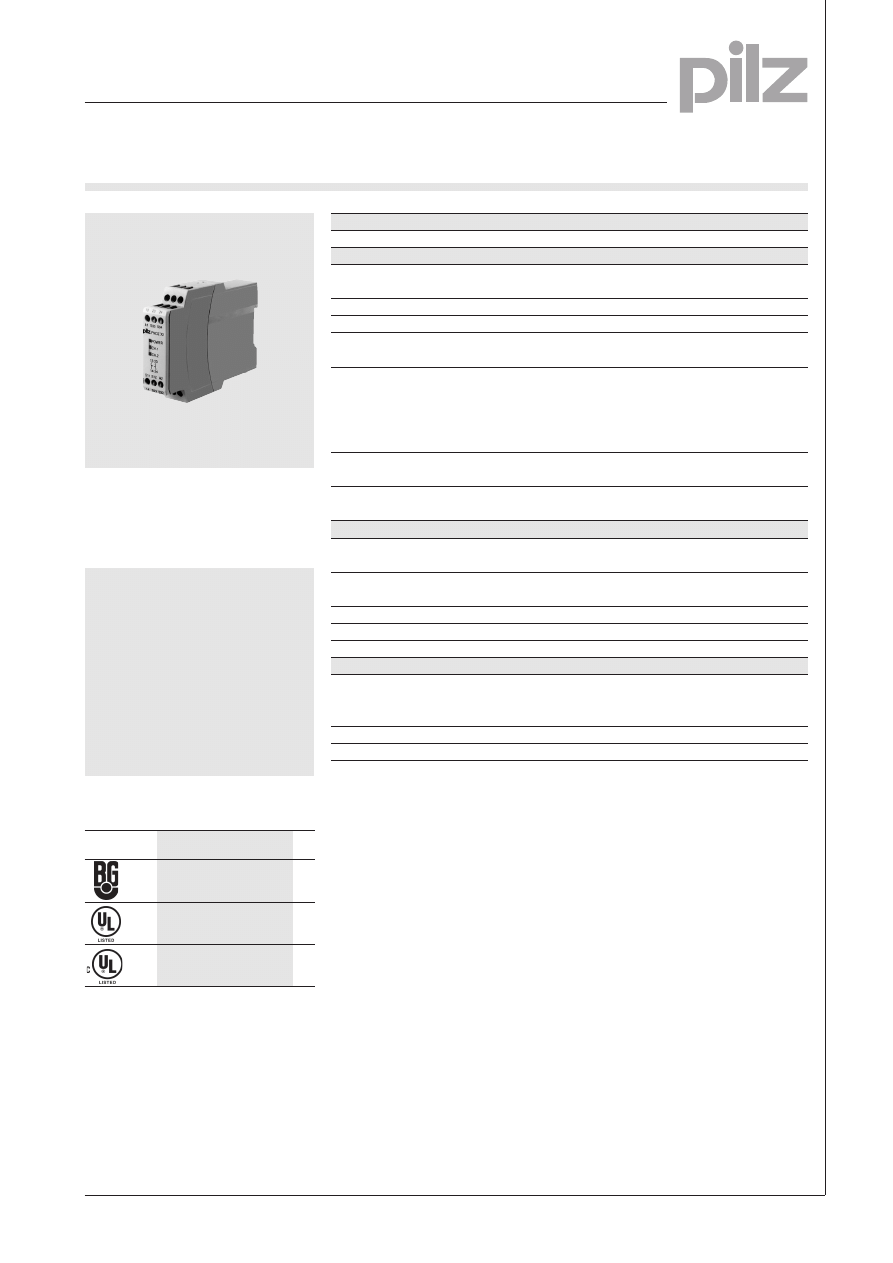
PNOZ X2, PNOZ X2.1, PNOZ X2.2
Emergency stop relay and safety
gate monitor in accordance with
VDE 0113-1 Part 1, 11/98 and
EN 60204-1, 12/97.
Features
l Dual-channel operation which
detects shorts across the input
contacts
l Supply voltage: 24 VAC/DC
l PNOZ X2: monitored manual
reset only
l PNOZ X2.2: several units may
be started in parallel using one
reset button
Approvals
Technical Details
PNOZ X2, PNOZ X2.1, PNOZ X2.2
Electrical Data
Supply Voltage
AC: 24 V
DC: 24 V
Tolerance
85 ... 110 %
Power Consumption
Approx. 2 W/2 VA
Voltage and Current at the Input and
24 VDC/25 mA
Reset Circuits and Feedback Control Loop
Switching Capability in accordance with
EN 60947-4-1, 10/91
AC1:
240 V/6 A/1500 VA
DC1: 24 V/4 A/100 W
EN 60947-5-1, 10/91
AC15: 230 V/5 A; DC13: 24 V/4A
(DC13: 6 cycles/min.)
Output Contacts
2 safety contacts (N/O)
EN 954-1, 07/96, category 4
Contact Fuse Protection
6 A quick or 4 A slow
(EN 60947-5-1, 10/91)
Times
Delay-on Energisation
Automatic reset: max. 150 ms
Manual reset: max. 100 ms
Delay-on De-energisation Single-channel input circuit: max. 1
20 ms
Dual-channel input circuit: max. 30 ms
Recovery Time
Approx. 1 s
Simultaneity channel 1/2
¥
Max. Supply Interruption before De-energisation
Approx. 10 ms
Mechanical Data
Maximum Cross Section of
2 x 1.5 mm
2
or 1 x 2.5 mm
2
External Conductors
Single-core or multi-core with
crimp connectors
Dimensions (H x W x D)
87 x 22.5 x 122 mm
Weight
220 g
Description
l 22.5 mm, S-95 housing, DIN-Rail
mounting
l Positive-guided relay outputs:
2 safety contacts (N/O)
l Connections for
– E-STOP button or safety gate
limit switch
– reset button
l Detects shorts across the input
contacts
l LEDs for channel 1, channel 2 and
power
l Increase in the number of
safety contacts available by
connecting expander modules.
Operating Modes
l Single-channel operation
l Dual-channel operation
l Manual reset
l PNOZ X2 only: monitored manual
reset
PNOZ X2/X2.1/X2.2
l
l
l
Pilz GmbH & Co., Felix-Wankel-Straße 2, 73760 Ostfildern, Deutschland NSG-D-2-053-
11/01
Telefon +49 (7 11) 34 09-0, Telefax +49 (7 11) 34 09-1 33, E-Mail: pilz.gmbh@pilz.de
l PNOZ X2.1 only: automatic
reset
l PNOZ X2.2 only: as the PNOZ X2
but any number of units can be
connected in parallel to one or
more reset buttons
1
Emergency Stop Relays, Safety Gate Monitors
Category 4, EN 954-1
PNOZ X2, PNOZ X2.1, PNOZ X2.2
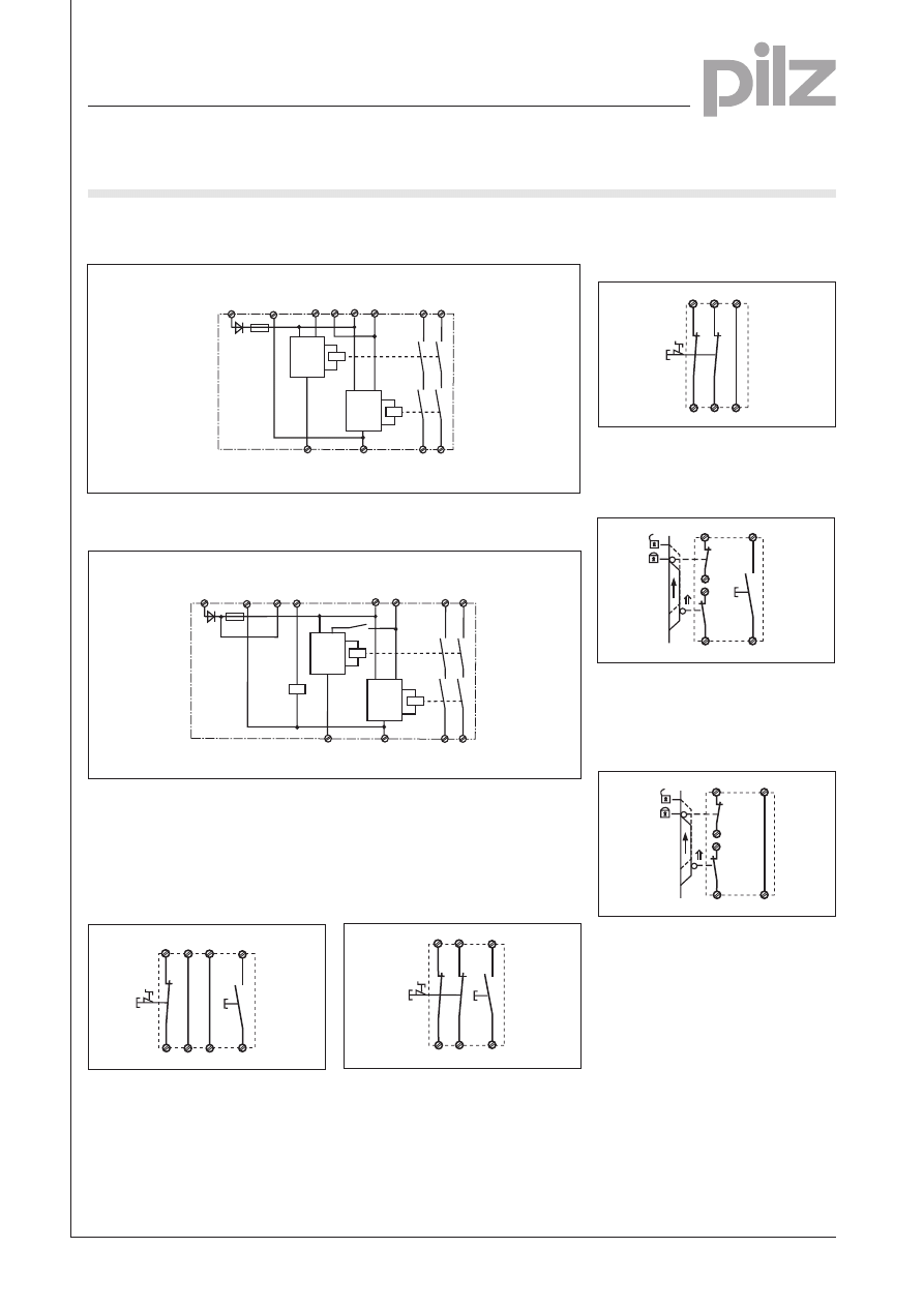
Internal Wiring Diagram
– PNOZ X2, PNOZ X2.1
External Wiring
l Example 1
Single-channel E-STOP wiring with
monitored manual reset, delay-on
de-energisation: max. 100 ms
S11
S12
S34
S22
S33
S21
UB
(L+)
A1
S1
S3
l Example 4
Dual-channel safety gate control
through forced-contact limit switches
with position monitoring.
l Example 2
Dual-channel E-STOP wiring with
monitored manual reset.
S11
S12
S34
S22
S33
S21
S1
S3
l Example 3
PNOZ X2.1 only: dual-channel
E-STOP wiring with automatic reset.
S11
S12
S34
S22
S33
S21
S1
l Example 5
PNOZ X2.1 only: dual-channel safety
gate control with automatic reset.
S34
S33
S11
S22
S12
S21
S1
S1
S2
S34
S33
S11
S22
S12
S21
S1
S3
S1
S2
A1 (L+)
A2 (L-)
S22
S12
S21
S11
S33
13
14
K1
K2
23
24
S34
Start
Unit
Start
Unit
Reset
circuit
Input circuit
Safety
contacts
Input
circuit
UB
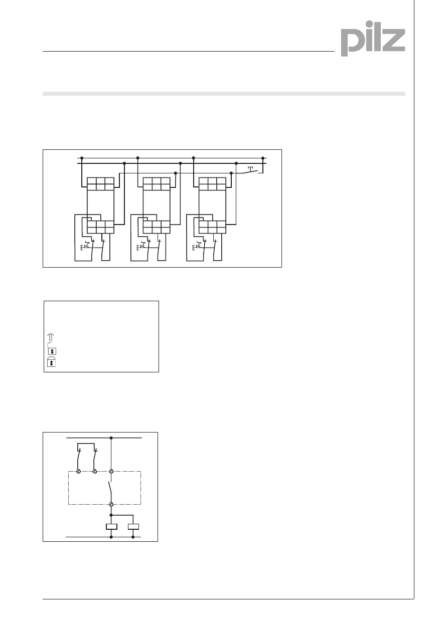
– PNOZ X2.2
A1 (L+)
A2 (L-)
S22
S12
S21
S11
S34
13
14
K1
K2
23
24
S33
Start
Unit
Start
Unit
Reset
circuit
Input circuit
Safety
contacts
Input
circuit
U
B
K3
K3
Pilz GmbH & Co., Felix-Wankel-Straße 2, 73760 Ostfildern, Deutschland NSG-D-2-053-
11/01
Telefon +49 (7 11) 34 09-0, Telefax +49 (7 11) 34 09-1 33, E-Mail: pilz.gmbh@pilz.de
1-3
1
S1/2:
E-STOP or safety gate switch
S3:
Reset button
Switch operated
Gate open
Gate closed
– Key
14
K4
K5
13
S33
S34
K4
K5
1L1
1L2
l Increase in safety contacts
The number of output contacts can
be increased by using expander
modules or relays/contactors with
positive-guided contacts.
A1
13 23 24
S33 S34
S11 S12 A2
14 S21 S22
S1
A1
13 23 24
S33 S34
S11 S12 A2
14 S21 S22
S1
A1
13 23 24
S33 S34
S11 S12 A2
14 S21 S22
S1
+24 V DC
0 V
S3
l Example 6
PNOZ X2.2 only: dual-channel
E-STOP wiring where units can be
started in parallel using one reset
button.
Emergency Stop Relays, Safety Gate Monitors
Category 4, EN 954-1
PNOZ X2, PNOZ X2.1, PNOZ X2.2
Pilz GmbH & Co., Felix-Wankel-Straße 2, 73760 Ostfildern, Deutschland NSG-D-2-053-
11/01
Telefon +49 (7 11) 34 09-0, Telefax +49 (7 11) 34 09-1 33, E-Mail: pilz.gmbh@pilz.de
1
Emergency Stop Relays, Safety Gate Monitors
Category 4, EN 954-1
PNOZ X2, PNOZ X2.1, PNOZ X2.2
Pilz GmbH & Co., Felix-Wankel-Straße 2, 73760 Ostfildern, Deutschland NSG-D-2-053-
11/01
Telefon +49 (7 11) 34 09-0, Telefax +49 (7 11) 34 09-1 33, E-Mail: pilz.gmbh@pilz.de
General Technical Data
Unless stated otherwise in the technical details for the specific unit
Electrical Data
Frequency Range AC
50 ... 60 Hz
Residual Ripple DC
160 %
Contact Material
AgSnO
2
Continuous Duty
100 %
Environmental Data
EMC
EN 50081-1, 01/92, EN 50082-2, 03/95
Vibration in accordance with
Frequency: 10 ... 55 Hz,
EN 60068-2-6, 04/95
Amplitude: 0.35 mm
Climatic Suitability
DIN IEC 60068-2-3, 12/86
Airgap Creepage
DIN VDE 0110 part 1, 04/97
Ambient Temperature
-10 ... +55 °C
Storage Temperature
-40 ... +85 °C
Mechanical Data
Torque Setting on Connection Terminals
0.6 Nm (screws)
Mounting Position
Any
Housing Material
Thermoplast Noryl SE 100
Protection
Mounting: IP 54
Housing: IP 40
Terminal Range: IP 20
The units were tested in accordance with the relevant standards current at
the time of development.
Order References
Type
U
B
Order No.
PNOZ X2
24 V AC/DC
774 303
PNOZ X2.1
24 V AC/DC
774 306
PNOZ X2.2
24 V AC/DC
774 607
Wyszukiwarka
Podobne podstrony:
więcej podobnych podstron