file:///H|/Modellismo/AFV%20Interiors/[armor]%20-%20AFV%20Interiors/afvinteriors.hobbyvista.com/lvt(a)4/lvt(a)4.html
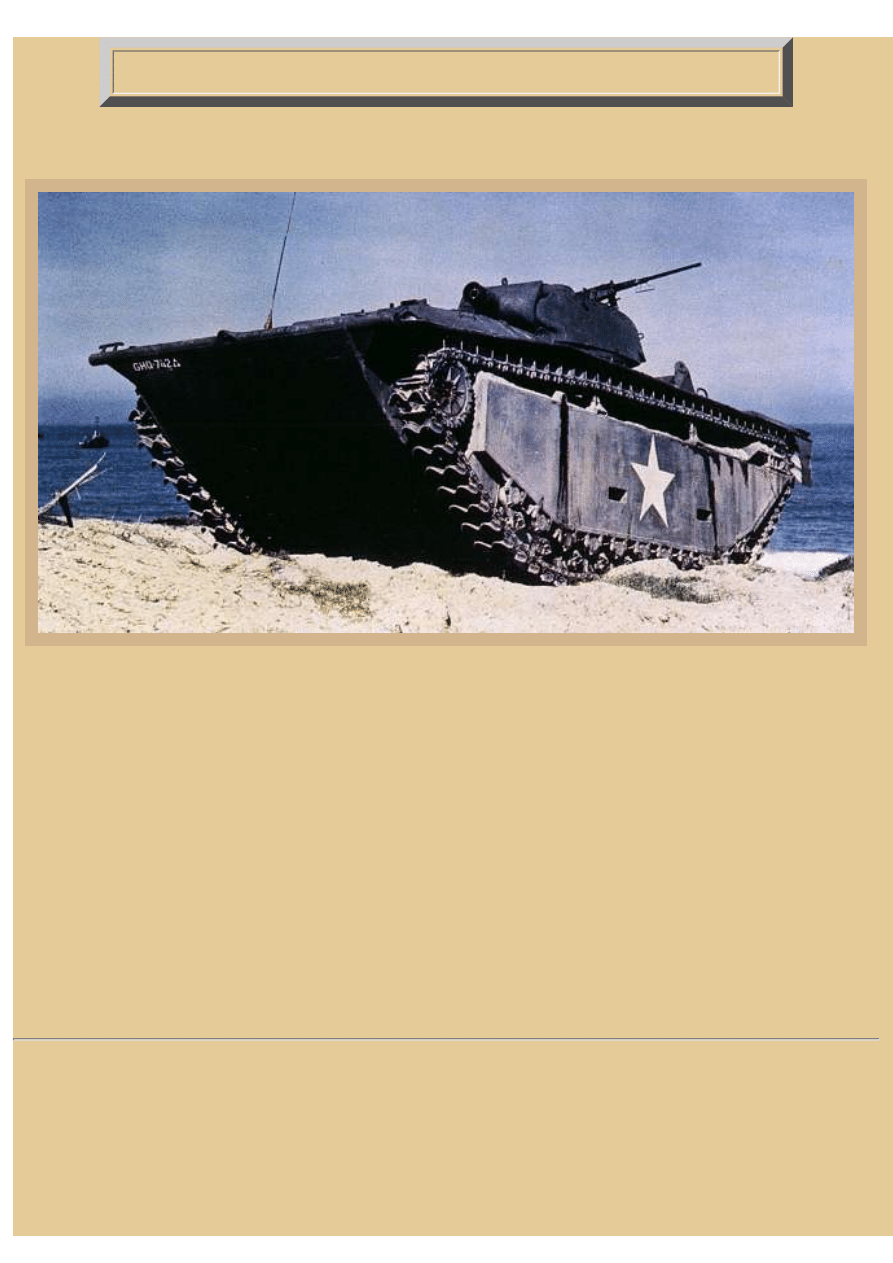
US Landing Vehicle, Tracked, LVT(A)4
Picture 1:
In brief, there were two types of amphibious vehicles developed by the Americans in WWII to cross the shoals and
beaches in the Pacific theater. One was the personnel carrier, or LVT (landing vehicle, tracked), generally equipped
with a ramp in the rear (like the LVT(4) seen elsewhere in AFV INTERIORS) which allowed troops to debark quickly
under some cover; and the LVT(A), or armored amphibian, which was actually an amphibious tank. Although their
names are similar, the LVT(A)4 was an entirely different machine from the LVT(4) vehicle. The LVT(A)4 was
derived from the earlier LVT(2) Amtracs. Production for the new "Amtank" vehicles began in 1944, the LVT(A)4
being born from the US Marines' urgent request for increased turret firepower from the earlier (A)1's high velocity
37mm weapon (mounted in a M3 type turret). The result was the substitution of a 75mm howitzer (mounted in a M8
type turret) which considerably improved the potential for enemy bunker busting. But, in order to mount the M8 style
turret on the roof of the (A)1, it was necessary to make some modification to the upper hull. These included increasing
the size of the turret ring and lengthening the hull rear to provide space for the cramped engine compartment.
We only have a few illustrations of the interior of this important Amtank, so I have made each of the images large to
show off the greatest amount of detail. This is a headquarters Amtank photographed by the Navy during joint Army/
Navy training maneuvers.
file:///H|/Modellismo/AFV%20Interiors/[armor]%20-%20AFV%...teriors/afvinteriors.hobbyvista.com/lvt(a)4/lvt(a)4.html (1 di 7)07/02/2007 22.20.09
file:///H|/Modellismo/AFV%20Interiors/[armor]%20-%20AFV%20Interiors/afvinteriors.hobbyvista.com/lvt(a)4/lvt(a)4.html
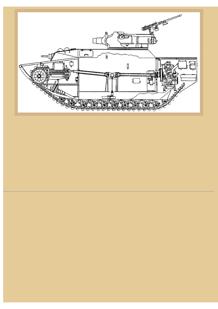
Picture 2:
The full crew compliment of the LVT(A)4 consisted of six men-- a driver and assistant driver/radio operator forward
in the bow, a gunner and loader up in the turret, and a commander and ammunition handling cannoneer usually located
down inside the hull. The hull is little modified from the very early Amtrac vehicles and includes the same Continental
engine, located in the rear of the vehicle this time, with the drive shaft passing through the length of the hull on its way
to the front transmission. The very early (A)4s had clear plastic domes mounted over both drivers' over-head M6
periscopes on their front hatches. But when the change was made to mount a .30cal MG in front of the assistant
driver's seat, flaps with vision slits were added to the front window plate and the over-head periscopes were typically.
This drawing shows one of these later vehicles with the bow MG visible, but for some reason the domes are still
intact. Initially, the M8 howitzer turret was modified very little from its self-propelled ancestor, and we will be using
here mostly interior illustrations of the M8 turret. Some of the items identified in the original sketch include a number
of electrical junction boxes on the hull wall and in the engine compartment at the rear.
file:///H|/Modellismo/AFV%20Interiors/[armor]%20-%20AFV%...teriors/afvinteriors.hobbyvista.com/lvt(a)4/lvt(a)4.html (2 di 7)07/02/2007 22.20.09
file:///H|/Modellismo/AFV%20Interiors/[armor]%20-%20AFV%20Interiors/afvinteriors.hobbyvista.com/lvt(a)4/lvt(a)4.html
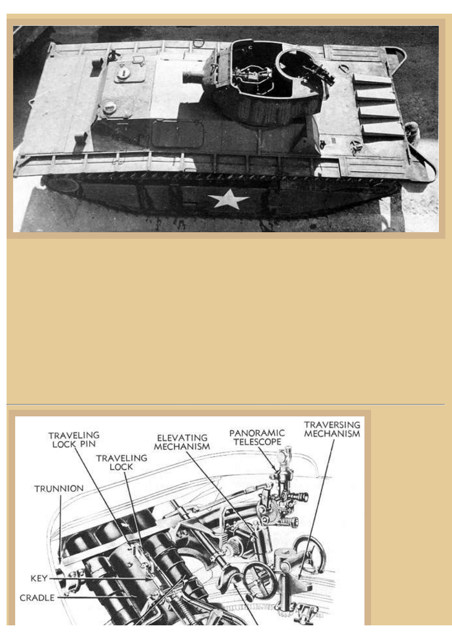
Picture 3:
The (A)4 was not intended to be a cargo or troop carrying vehicle. It was a tracked amphibious "tank" and the space
inside the hull was completely taken up with ammo and personal kit for the six crewmen. This Army photo shows the
general appearance of the top of the Amtrac, illustrating the driver's front plate and hatches of an early vehicle with
M6 periscopes in both of the over-head hatches and with no sign of a bow MG. The open topped turret mounts a
75mm howitzer M3 in its M7 mount, with only manual traverse and elevation. The secondary armament consisted
initially of a .50cal Browning HB M2 on a ring mount on the rear of the turret, but later vehicles mounted two .30cal
MGs on the sides of the turret in place of the .50cal MG. There is a floor platform below the turret, but it does not
rotate with the turret, requiring the turret crew to walk around with the turret if they are not in their suspended seats.
The rear mounted engine is the same Continental W-670-9A seen in the LVT(4), driving a Synchromesh transmission
located between the drivers. The driver's controls are also very similar to the LVT(4), with the general layout of the
cab equal in most ways. fighting vehicle.
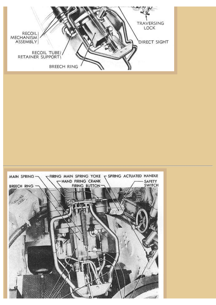
Picture 4:
The howitzer
gunner sat to the
right of the gun on
a small black seat
suspended from
the turret ring. The
other crewman,
the loader, sat to
the left of the
weapon, also in a
suspended seat.
This TM drawing
shows the basic
controls for the
turret and gun.
The howitzer is
flanked on both
file:///H|/Modellismo/AFV%20Interiors/[armor]%20-%20AFV%...teriors/afvinteriors.hobbyvista.com/lvt(a)4/lvt(a)4.html (3 di 7)07/02/2007 22.20.09
file:///H|/Modellismo/AFV%20Interiors/[armor]%20-%20AFV%20Interiors/afvinteriors.hobbyvista.com/lvt(a)4/lvt(a)4.html
sides by large
recoil cylinders
and the breech is a
manual horizontal
sliding wedge
type. The
elevating hand
wheel is seen to
the right,
connected to an
elevating pinion
gear, and the
traverse wheel is
even farther to the right, connected by drive extension to the geared hull ring. Elevation is +40 to -20 degrees and the
weapon utilized a percussion primer system, which could be fired either manually or electrically. Manual firing was
via a pull chain attached directly to the firing mechanism. Electrical firing was via a solenoid to the firing pin with the
solenoid controlled by a large firing button just forward of the gunner. Also visible here is the M70C direct vision
telescopic sight and a M12A5 panoramic telescope off to the right that was also available for indirect firing.
The LVT(A)4's 75mm gun was not stabilized in any way and its accuracy when firing on the move was dismal. This
was rectified with the next model, LVT(A)5 that came complete with elevation gun stabilisation, as well as hydraulic
turret traverse and a rotating turret floor. The non-rotating turret platform underneath the turret of the LVT(A)4 was
placed just above the drive shaft and the remainder of the hull was filled with ammunition, crew personal gear and
weapons, and an auxiliary generator located at the right rear. There were stowage racks for at least 100 rounds of
75mm ammo, with other gear mounted on the walls included grenade boxes, first aid kits, water canteens and other
miscellaneous items. Access to the hull was generally via the two hatches on the opposite sides of the oblique sloping
upper hull, although it was possible to also enter the LVT(A)4 via the driver's cab hatches or through the open topped
turret.
Picture 5:
This TM photo shows
the same general area in
the M8 turret with the
75mm howitzer, but
with a broader
perspective of the
fighting compartment.
Early production LVT
(A)4 turrets were exactly
the same as the standard
turret from the M8 self-
propelled howitzer that
we see here. Mid and
late production LVT(A)
4 turrets had the partial
roof at the rear of the
turret opening removed,
along with the .50cal
MG mount, and vision
protectoscopes were
added to both sides of
the turret and also to the
file:///H|/Modellismo/AFV%20Interiors/[armor]%20-%20AFV%...teriors/afvinteriors.hobbyvista.com/lvt(a)4/lvt(a)4.html (4 di 7)07/02/2007 22.20.09
file:///H|/Modellismo/AFV%20Interiors/[armor]%20-%20AFV%20Interiors/afvinteriors.hobbyvista.com/lvt(a)4/lvt(a)4.html
rear. As I mentioned
before, later turrets had
two .30cal MGs pintle
mounted on each side
and they were usually
provided with flat armor shields for gunner protection, something lacking in the earlier .50cal mountings.
Looking at this photograph you can see the elevation hand wheel at the right, but the traverse wheel is out of view.
Mounted forward of the elevation wheel is the large firing button with a smaller safety button on the top of the
mounting box. Both of the large recoil cylinders can be seen to either side of the howitzer barrel.
The top of the breech ring and recoil area are a mass of springs, tubes and wiring and very difficult to understand- let's
see if we can make some sense of all this. Because the howitzer could be fired either electrically or by pull chain, the
breech has accommodations for both firing methods. The large spring along the top keeps tension on the trigger until it
is hand pulled by the smaller chain hanging to the right of the breech. The electrical solenoid is located at the left rear
of the breech and is partially hidden by the recoil guard that surrounds the entire breech of the weapon. If you look
closely you may see the electric wire leaving the firing solenoid and snaking its way toward the right side of the
breech ring. And you may also see the large firing button in front of the gunner. When he pressed the firing button, the
solenoid would activate and its plunger would push the firing trigger on the breech ring (the same trigger that would
fire the weapon when the attached pull chain was pulled).
Ammunition for the 75mm gun included M48 HE (High Explosive), M41A1 HE, M66 HEAT (High Explosive Anti
Tank-- this was a shaped charge), and M64 WP (White Phosphorus- smoke). Muzzle velocity was a bit better than
1,000fps for the HE and maximum range was up to 10,000yds and 8,000yds for HEAT. The firepower was greatly
appreciated not only by the crews of the Amtracs, but also by the men they accompanied onto the beach.
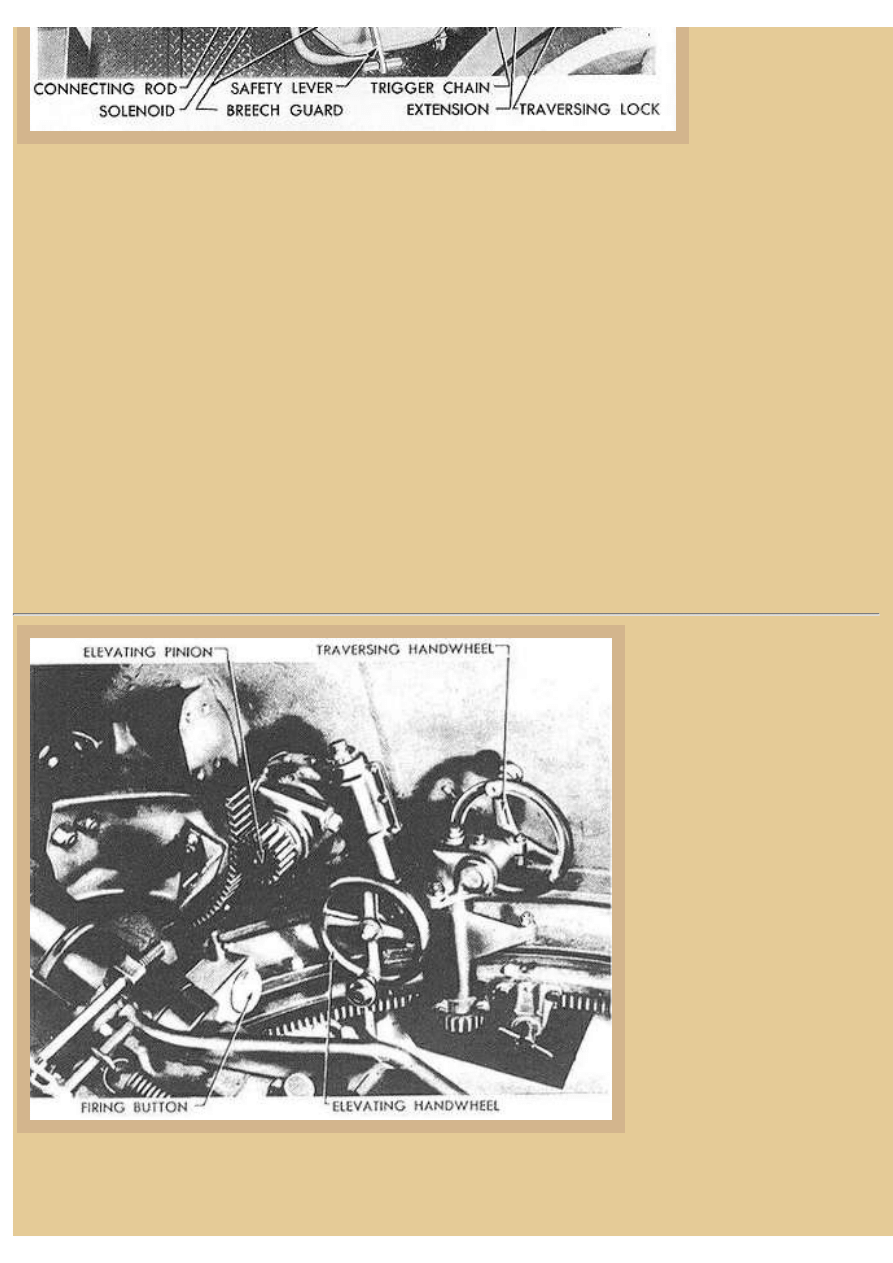
Picture 6:
A close up image from the M8
TM of the gunner's position to
the right of the howitzer provides
some detail of the equipment in
this area. The elevation
handwheel is clearly visible at the
right side of the picture and its
simple connection to the traverse
gearbox and turret ring can also
be seen. Down next to the
traverse pinion gear is the turret
lock, which consists of a simple
screw device that forces a pin
into the space between teeth in
the turret ring gearing. Notice
that the traverse handwheel is
mounted very near the turret wall
and the gunner's right hand
almost scrapes the turret when he
rotates the wheel.
In the center of the image is the
elevation handwheel, and again
the gearing is clearly seen with its pinion engaging the rack gear of the gun mount. We also have a view here of the
firing button directly in front of the gunner as well as some of the top of the breech, including the large firing pin
retaining spring that has been so prominent in many of these images.
file:///H|/Modellismo/AFV%20Interiors/[armor]%20-%20AFV%...teriors/afvinteriors.hobbyvista.com/lvt(a)4/lvt(a)4.html (5 di 7)07/02/2007 22.20.09
file:///H|/Modellismo/AFV%20Interiors/[armor]%20-%20AFV%20Interiors/afvinteriors.hobbyvista.com/lvt(a)4/lvt(a)4.html
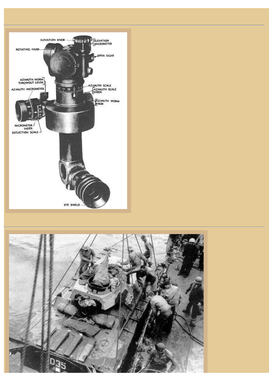
Picture 7:
This picture illustrates an indirect panoramic sighting
system used most commonly in both the M8 self-propelled
howitzer and the LVT(A)4 Amtank. Most of the identifying
labels are visible here so you should have no problem
determining how the sight was adjusted in use. Notice that
as with most indirect sighting systems, this one has a
rotating sight head that can view in any direction without
having to move the ocular at the bottom. Of course a
gunner's quadrant could also be used to determine elevation
for indirect shoots.
Initially, most Army and Marine Amtracs are reported to
have been painted US Navy ocean gray on their exterior
surfaces, but in May of 1944 new orders required all
vehicles to be refinished in olive drab when repainting
became necessary. The olive drab was to be applied to both
the vehicle exterior and also to interior surfaces of open-
hulled vehicles and those equipped with open-topped
turrets. Other interior surfaces which were not visible from
a position above the vehicle were to be repainted the typical
glossy white, which would include the driver's position in
the LVT(A)4 Amtank.
Picture 8:
This National Archives
photo shows an LVT(A)
4 being lowered into the
water as its crew climbs
on board. Notice that a
protective steel tub as
been mounted at the
position for the .50cal
gunner on the turret.
D35 has an interesting
camo paint job and
armored covers for the
rear air louvers over the
engine compartment.
The LVT(A)4 was first
used in the Marianas
campaign during the
invasion of Guam,
Tinian and Saipan. The
file:///H|/Modellismo/AFV%20Interiors/[armor]%20-%20AFV%...teriors/afvinteriors.hobbyvista.com/lvt(a)4/lvt(a)4.html (6 di 7)07/02/2007 22.20.09

file:///H|/Modellismo/AFV%20Interiors/[armor]%20-%20AFV%20Interiors/afvinteriors.hobbyvista.com/lvt(a)4/lvt(a)4.html
US Marines used 533 of
the vehicles to equip
three Amtank battalions
while the US Army put together seven Amtank battalions with the 1,307 LVT(A)4s they acquired. There were perhaps
as many as 50 additional vehicles supplied to the Allies under Lend-Lease agreements.
The LVT(A)4 weighed around 38,000lbs and could manage five knots in water and around 25mph on land. Total
capacity of ammunition and gear was about 2,000lbs. Most US Marine Amtank units organized their platoons into
artillery batteries and were trained by artillerymen from Marine divisions. The value of these vehicles as artillery was
that they were with the first troops ashore and they could then quickly be in position to provide supporting fire for the
attacking Marine and Army units. In comparison, it could take hours to deliver conventional artillery onto the beaches
and set up fire missions. Once ashore, the Amtanks became an integral part of the massed artillery bombardment of
entrenched Japanese defenses and because of their amphibious abilities, they had a maneuver flexibility that was
lacking in conventional artillery units.
BACK TO AFV INTERIORS HOME PAGE
(c) 2001, 2003 AFV INTERIORS Web Magazine
file:///H|/Modellismo/AFV%20Interiors/[armor]%20-%20AFV%...teriors/afvinteriors.hobbyvista.com/lvt(a)4/lvt(a)4.html (7 di 7)07/02/2007 22.20.09
Document Outline
Wyszukiwarka
Podobne podstrony:
więcej podobnych podstron