
SPECIAL ISSUE - ORIGINAL ARTICLE
New approaches for an automated production
in ultra-precision machining
C. Brecher
&
M. Weinzierl
Received: 15 June 2008 / Accepted: 7 May 2009 / Published online: 28 May 2009
# Springer-Verlag London Limited 2009
Abstract Automation solutions ensure determinism and
reproducibility for the handling and aligning of work pieces
and tools in micro- and ultra-precision technologies.
Automation in this context means the handling and
alignment of parts and tools within the entire process chain
to achieve adjustment and alignment accuracies at a level
well below 0.5
μm. The exact knowledge about the
position and the condition of the work pieces and tools
throughout the entire process chain is the key issue in the
automated production chain. This knowledge enables the
exact referencing of the work piece within the machine tool
coordinate system and an offset compensation by the
machine tool axes as well as by active work piece clamping
devices. The automation solutions enable a cost-effective,
ultra-high quality production technology for the achieve-
ment of nanometre form accuracies and super smooth
surface finishes. These are required for ultra-precise
components in biomedical-, sensor- as well as consumer
goods applications and are revolutionary throughout the
world's technologies.
Keywords Micro-optics . Ultra-precision machining .
Sub-micrometre referencing . Automation
1 Introduction
In ultra-precision machining, non-ferrous metals as well as
polymers are micro-structured by planing, fly-cutting or
turning processes with single crystal diamond tools [
These processes project the tool's geometry into the work
piece surface to generate micro-structures with sub-micron
accuracy. The initial step in this machining process, the
alignment of the tool tip relative to the work piece surface,
has a significant impact on the overall accuracy of the work
piece. This is especially true if numerous work pieces have
to be machined with identical precision. But also, the ultra-
precision machining of nickel coated steel work pieces,
where the nickel coating with thicknesses of less than
100
μm is the only section which can be machined with
single crystal diamonds, is critical. The initial alignment
precision can decide whether the coating is cut through or
not. In the first case, fatal tool damage and an overall
destruction of the work piece is the result. Therefore, using
ultra-precision machine tools is only half the solution to
manufacture high-quality work pieces with sub-micron
accuracy. To a large amount, it is the experience and skill
of specially trained ultra-precision machining experts which
decides whether an ultra-precision machining task is
successful or not. As a consequence, automation has not
yet been established in ultra-precision machining, and the
worldwide process know-how is strongly linked to those
ultra-precision machining experts and the machines they
use.
To ensure a highly precise and reproducible machining
of work pieces in micro- and ultra-precision machining,
automated alignment and referencing solutions are devel-
oped at the Fraunhofer IPT. Automation in this context
means the similar alignment of work pieces within less than
0.5
μm on several machine systems of an automated
production chain. This is mainly obtained by maintaining
an exactly defined position of the work piece throughout
the entire process chain. Such automation aspects enable
the achievement of nanometre form accuracies and super-
Int J Adv Manuf Technol (2010) 47:47
–52
DOI 10.1007/s00170-009-2099-3
C. Brecher
:
M. Weinzierl (
*)
Fraunhofer-Institute for Production Technology IPT,
Aachen, Germany
e-mail: Martin.weinzierl@ipt.fraunhofer.de
URL:
www.ipt.fraunhofer.de
smooth surface finishes, as they are required for global
standard for ultra-precise components in bio-medical-,
sensor- as well as consumer goods applications.
In this paper, the research work which is done towards the
automation in ultra-precision machining is presented by
means of the single automation degrees which have been
developed at Fraunhofer IPT within the last 4 years. The first
step in automation is the referencing of tools within the
machine coordinate system (MCS). This does not only offer
the possibility to exchange damaged tools but to use different
shaped tools to structure a work piece on one machine tool
without losing precision. The second step is the automated
referencing of the work piece, i.e. defining the true position of
the work piece surface within the MCS and to position the
tool tip at an exact position relative to the work piece surface.
In the third step, the first two automation steps are combined
to develop a fully automated ultra-precision process chain
which incorporates different machine tool and metrology
systems. The automation solutions which are presented in this
paper have been designed for the diamond milling process
“fly-cutting” which is mainly applied for the machining of
ultra-precision optical components.
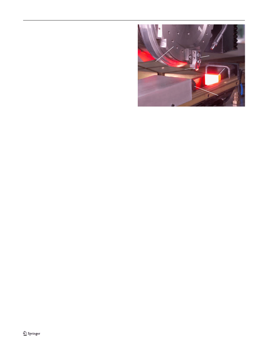
2 Automated tool referencing in ultra-precision
machining
The accuracy of the relative position between the tool and the
work piece is decisive to obtain the specified geometry with
high-form accuracies when ultra-precision machining work
pieces with sub-micron tolerances. Misalignments of the tool as
well as tool wear result in form inaccuracies and increased
surface roughness of the structure. Therefore, automated tool
referencing systems have been developed at the Fraunhofer
IPT. These systems enable to define the tool's position within
the machine coordinate system prior to and during the
machining process with an accuracy down to 0.1
μm.
Translational offsets between two different tools can be
detected and compensated by appropriate axis movements of
the machine tool. This enables an exchange of worn or broken
tools as well as the setup of different tools for the same work
piece. Besides a higher process stability, this means an
increase in complexity of the micro-structures which can be
machined when using different shaped diamond tools.
During rigging, the tool is pre-aligned on the spindle rotor
by passive alignment with an accuracy of approximately
5
μm. This repeatability is by far not enough for the required
machining precision but it is sufficient to position the tool
within the measuring range of 480×360
μm of the measuring
device which actively detects the translational offset between
the exchanged tool and the original tool (see Fig.
).
The tool which has been used to make the first cut
determines the relative position between the tool tip and the
work piece. This first tool is the reference to detect the
offset of the tools in follow-up exchange procedures. By
referring to this reference tool, the addition of measurement
uncertainties is avoided, which would occur if each tool
would be compared to the previous one.
The measuring device consists of a charge-coupled device
(CCD) camera combined with a telecentric objective and has a
hardware resolution of 0.465
μm. A software is used to measure
the tool positions and to calculate the offset between the tools.
The values of the horizontal and vertical tool offsets are
directly forwarded to the programmable logic control of the
machine tool and fully automatically are processed within the
next steps of the numerical control (NC) programme through
special function calls.
The accuracy of the tool offset detection is influenced by
the repeatable positioning accuracy of the tool within the
measurement range and by the measurement uncertainty of
the system. The positioning of the tool is mainly influenced
by the accuracy of the mechanical fixation of the spindle
rotor, which lies within a range of ±5
μm. In combination
with a maximum misalignment of the camera of 0.01°, the
resulting deviations account for 0.3
μm.
The standardised design of the tool retainers enables the
integration of fitting surfaces to define the tool's position on
the spindle rotor by passive alignment. The tool itself is
adjusted appropriately within the retainer prior to machin-
ing. This is done with the help of the measurement device
which can be swivelled by 90° so that all rotational
displacements can be detected.
The verification of the active and passive tool alignment
has been done by analysing the cross-section of v-groove
structures which have been cut with two different tools. The
depths of the v-grooves have been measured at constant
distances in horizontal direction. The change in depth and
pitch between the two grooves where the tool change has
been accomplished differs by less than 0.4
μm which lies
Spindle rotor
Retainer
Diamond tool
Illumination
CCD-camera
Fig. 1 Optical setup for the detection of the tool offset
48
Int J Adv Manuf Technol (2010) 47:47
–52

within the range of the measurement uncertainty of the
analysis [
3 Automated work piece referencing in ultra-precision
machining
Due to the lack of adequate high-precision referencing
systems, manual rigging of the work piece is the most
commonly used to meet the demands of ultra-precision
machining today. The main reason for this is that with the
expertise of ultra-precision machining specialist, a referenc-
ing accuracy can be reached no automation or robot system
can cope with. Nevertheless, this manual work is still the
biggest influence on the accuracy on ultra-precision (UP)
micro-structures. Whereas ultra-precision machine tools are
capable of positioning accuracies well below 100 nm, even
the most experienced UP-specialist is most unlikely to
reach this precision when determining the initial position
between the tool and the work piece surface.
Consequentially, high-precision metrology devices have
been integrated into the ultra-precision machine tool at the
Fraunhofer IPT. These allow for automated detection of the
actual work piece position within the machine coordinate
system prior to and during the machining process. This
enables not only the structuring of high-precision work
pieces but increases the flexibility of the ultra-precision
machining towards multi-tool and multi-surface machining.
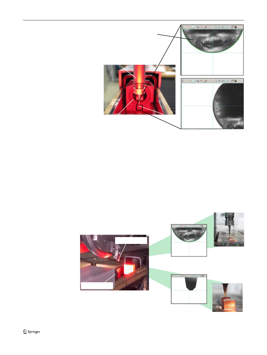
For ultra-precision referencing, the work piece position
can be determined with an accuracy up to 0.1
μm relative to
an affixed point within the machine coordinate system. This
is done by the use of a high-precision touch probe which is
calibrated to the cross hair of the CCD-camera system
which is used for the offset detection of the diamond tool
(see Fig.
).
After the calibration of the touch probe, the work piece
surface is auto touched, and the relative position vector is
calculated from the machine coordinates of the cross-hair
position of the touch probe and the contact points on the
work piece surface. Finally, the diamond tool is aligned to
the cross hair and then shifted towards the work piece by
the same relative position vector which has been deter-
mined previously (see Fig.
Due to a special strain gauge technology, the touch probe
enables the auto touching of the work piece surfaces with a
repeatable accuracy below 0.08
μm. In preliminary tests,
the work piece surface even has been auto touched with a
repeatable accuracy of 0.05
μm in vertical direction. Thus,
the referencing accuracy has clearly fallen below the
100 nm barrier. Compared to the manual work piece
referencing, where a typical accuracy of about 10
μm is
obtained, the referencing accuracy has increased by a factor
100 through the automated referencing process [
4 Fully automated ultra-precision production chain
Based on the results which have been obtained from the pre-
liminary work for tool and work piece referencing, automated
solutions for ultra-precision machining processes are developed
within the European Integrated Project
“Production4μ”.
The fundamental approach for the cost-effective, ultra-
high-quality automation in leading-edge production of
micro-optics and micro-tools for replication processes, such
as hot embossing or glass moulding, is the exact knowledge
of the position and the condition of the work piece
throughout the entire process chain. To enable such
knowledge, the work piece is handled throughout the
automated process chain on a standardised pallet which
contains all necessary information about the work piece.
To enable this procedure, the work piece is pre-positioned
on the pallet by passive alignment in the first step of the
automated process. Then, the exact position of the work
piece is determined relative to the pallet coordinate system
which is defined by three reference marks on the pallet. In
the further course of the production chain, the actual position
of the work piece within different machine-tool coordinate
systems can then be determined quickly by the calibration of
the pallet through its reference marks only. Deviations from
the default position can then be compensated by the machine
control. For the sensitive degrees of freedom of the
machining process which the machine kinematics cannot
compensate for, an active work piece alignment device is
implemented. The automated ultra-precision process chain
has been developed to enable a repeatable process control
with accuracies below ±0.25
μm
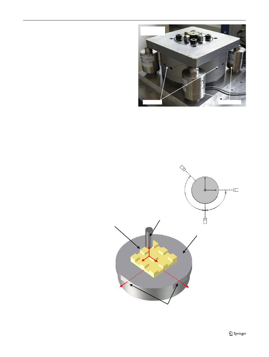
4.1 Reference station
The reference station is designed to enable the high-
precision measurement of the work piece position relative
to reference marks which are affixed on the carrier on
which the work piece is mounted. The reference station is
the first action taken in the automated production chain of
the high-precision manufacturing of micro-parts. All fol-
lowing alignment procedures refer to the reference marks
and the data recorded in the reference station. The accuracy
that is to be obtained hereby aims to be up to 0.1
μm. As
key data, the position of a distinctive point on the work
piece (
x-, y-, z-position) as well as the orientation of the
work piece (tilt-, roll- and yaw-angle) within the pallet
coordinate system is acquired. Additional information can
be acquired, if necessary (e.g. work piece tolerances,
surface roughness, material data).
The basic configuration for this referencing procedure
consists of three CCD cameras which are permanently fixed
in a relative position to a pallet clamping interface
—the so-
called chuck.
Int J Adv Manuf Technol (2010) 47:47
–52
49
The centre points of each camera system span a vector
space which defines the reference plane within the
associated coordinate system. The chuck accommodates
the carrier on which the work piece is mounted by passive
alignment. The carrier is furthermore equipped with
reference marks which are designed for optimum perfor-
mance with the CCD cameras. By measurement of the
reference mark positions within the field of view of each
camera, the relative position of the carrier within the
reference plane is determined. In addition, a high-
precision touch probe is calibrated within the reference
plane by the use of the cameras. With the aid of the touch
probe, the offset vector between the pallet coordinate
system and the work piece coordinate system can be
determined for different work piece geometries (see
Fig.
). Besides, the actual work piece tolerances can be
determined and taken into account when aligning the work
piece in following process steps.
The use of CCD cameras has the advantage that two
attributes (vertical and horizontal position) can be recorded
with one camera. The use of three cameras therefore allows
for full spatial position detection of the carrier within the
Work piece
touch-off
Touch probe
referencing
Diamond tool
referencing
Diamond tool
alignment
CCD-Camera
Diamond tool
Fig. 3 High-precision referenc-
ing of the work piece
Probe body
Stylus
500 µm
ruby ball at
stylus tip
CCD camera
Fig. 2 Calibration of the high-
precision touch probe
50
Int J Adv Manuf Technol (2010) 47:47
–52
coordinate system of the reference station. From these data,
the relative position of the work piece to the reference
marks can be calculated from the data obtained by the
tactile measurement with the touch probe. The use of a
touch probe enables the application of different measure-
ment strategies for optimum result, even when the work
piece has 3D features, e.g. cylindrical or spherical surfaces.
4.2 Active work piece alignment device
The active alignment device consists of an actuated chuck
system, which enables the accurate clamping of the work
piece with a repeatable accuracy < ±0.25
μm.
The active alignment chuck is based on a System 3R
“Macro” chuck/pallet system which is surrounded by three
cameras accordingly to the reference station setup. This
identical setup eliminates the influence of system-derived
errors. The major change for the in-machine use will be the
integration of an active chuck system which positions the
carrier according to the detected offset of the reference
marks. Due to high-precision passive alignment of the work
piece on the carrier and of the carrier on the chuck system,
the necessary travel of the active alignment device is
expected to be well below 50
μm. Therefore, the use of
rigid body joints becomes possible. These joints have the
big advantage that they lack play and can be designed for
stiffness and thus high process load.
The design which is shown in Fig.
incorporates high-
precision piezo actuators. The actuators are situated
x
WP
y
WP
z
WP
Work piece
x
P
y
P
x
WP
z
WP
Pallet
Touch probe
x
P
y
P
Reference marks
x
P
= pallet coordinate system
x
WP
= work piece coordinate system
x
P
= pallet coordinate system
x
WP
= work piece coordinate system
90
1
3
5
Camera 2
Camera 1
Camera 3
90
o
1
3
5
o
Top view on the
referencing set-up
Y
Z
X
Fig. 4 Referencing of the work
piece on the pallet
Piezo actuators
Pallet clamping
interface
Flexure joint
Fig. 5 Active alignment chuck system
Int J Adv Manuf Technol (2010) 47:47
–52
51

underneath each of the four corners of the top plate to
actuate the flexure joint unit. The use of four actuators is
necessary since each actuator provides a push force only.
Besides that, the arrangement with four actuators supports
the flexure joint unit in each of the weak spots arising from
the design of the cardan joint.
Inside the flexure joint unit, the clamping chuck is
attached against the top plate. By tilting the top plate, the
chuck is tilted as well. In this way, the pallet which is
clamped firmly on the chuck follows the motion of the
chuck, and thus, the angular position of the pallet and of the
work piece can be adjusted.
5 Summary and outlook
The integration of high-precision metrology devices has
proven the potential of automation in ultra-precision
machining. The diamond tool as well as the work piece
have been referenced with accuracies well below 0.5
μm in
semi-automated preliminary tests. Within the European IP
“Production4μ”, fully automated solutions are developed
which will cover the entire range of ultra-precision
machining processes. The implementation of the full
potential of automation will open new fields of applications
for ultra-precision machining. A special application area is
the full-surface compensation of shrinkage by means of
adaptation of the mould insert geometry which is especially
interesting for the production of high-precision optical
components. First investigations have shown that failure
effects caused by systematic manufacturing errors (such as
geometrical errors resulting from the actual shape of the
diamond tool's cutting edge) may be corrected if a
reproducible clamping of the work piece can be assured.
Measurement results from error detections can be utilised to
eliminate form deviations in iterative manufacturing steps
via tool path correction. Thus iterative quality loops can be
realised which is very valuable to realise a high-value
production chain in optics manufacturing.
Acknowledgements
The achievements presented in this paper are
the results from the public funded research projects
“GroßMikro”
(AIF), supports of the research association
“Ultraprecision Technolo-
gy
” (UPT) as well as the EC-funded Network of Excellence “4M” and
IP
“Production4μ”. The authors would like to thank the AIF, the UPT
and the European Commission for their support which enabled the
works done in the field of ultra-precision and micro-system technology.
References
1. Hesselbach J, Raatz A (eds) (2002) mikroPRO, Untersuchungen
zum internationalen Stand der Produktionstechnik, Schriftenreihe
des Instituts für Werkzeugmaschinen und Fertigungstechnik (iwf)
der TU Braunschweig. Vulkan-Verlag, Essen
2. Brecher C, Weinzierl M, Lange S, Peschke C (2006) Active and
passive tool alignment in ultraprecision machining for the manu-
facturing of highly precise structures. In: Production Engineering
—
Research and Development, Annals of the German Academic
Society for Production Engineering WGP 8, XIII/1, S. 193
–196
3. Weinzierl M (2006) Automatisierung in der Ultrapräzisionstechik.
In: Deutschlands Elite Institute-Fraunhofer IPT 2006 (2006), ISSN
1614-8185, pp 64
–65
52
Int J Adv Manuf Technol (2010) 47:47
–52
Document Outline
Wyszukiwarka
Podobne podstrony:
więcej podobnych podstron