
MANUAL GEARBOX: REMOVAL - REFITTING
Note, one or more warnings are present in this procedure
Tightening torques
Lower ball joint nut - 62 N.m
Track rod end nut - 40 N.m
Shock absorber base nut - 180 N.m
Engine tie-bar bolt on the gearbox (K7J, F8Q and D7F) - 62 N.m
Engine tie-bar bolt on the gearbox (D4F) - 105 N.m
Engine tie-bar bolt on the gearbox (K9K and K4M) - 110 N.m
Gearbox bell housing and starter bolts - 45 N.m
Suspended mounting nuts on the gearbox - 62 N.m
Driveshaft gaiter mounting bolts - 25 N.m
Steering box mounting bolts - 50 N.m
Subframe front mounting bolts - 62 N.m
Subframe rear mounting bolts - 105 N.m
Subframe - side member tie-rod bolts - 30 N.m
Subframe tie-rod bolts - 21 N.m
Gear control tie-bar mounting bolts - 28 N.m
Special tooling required (Optional)
Engine anchorage support with multiple adjustments and retaining straps - Mot. 1453
Ball joint extractor - Tav. 476
Support for removal - refitting of engine - gearbox assembly - Mot. 1390
REMOVAL
Position the vehicle on a two-post lift.
Disconnect the battery, starting with the negative terminal.
Remove:
The battery
The air filter unit
The engine undertray
Disconnect:
The injection computer
The preheating unit (diesel version)
The diesel filter (diesel version)
Remove the front bumper.
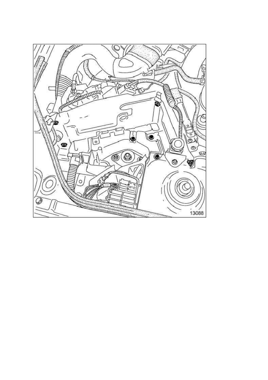
Remove:
The impact sensor
The battery protection plate mounting bolts
The battery protection plate
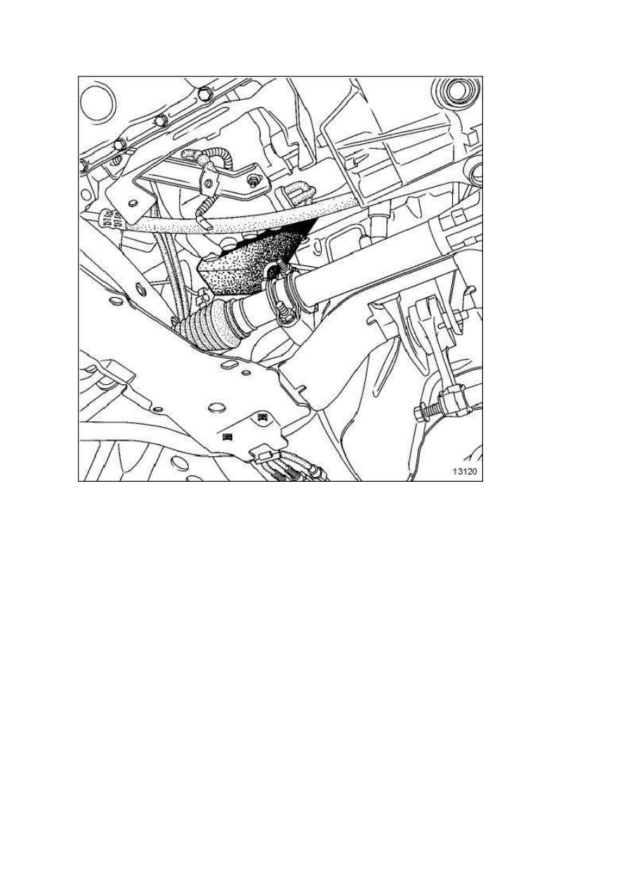
Remove the wiring harness mounting bolts (1) .
Disconnect the clutch cable.
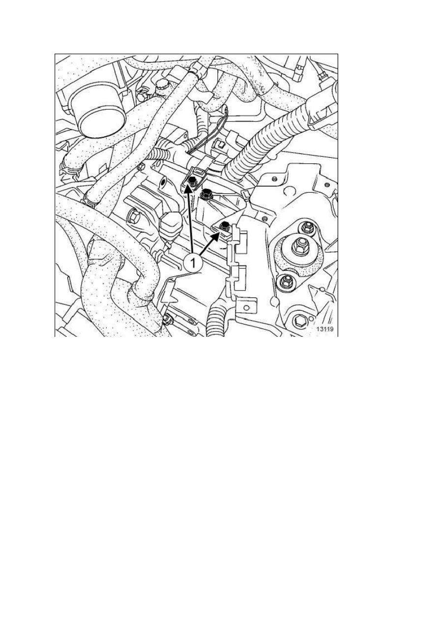
Remove:
The upper gearbox edge bolts and starter bolts
The earth strap bolt from the gearbox
The two TDC sensor bolts
Drain the gearbox.
Remove:
The front wheels
The wheel arches
On the left-hand side, remove the three driveshaft gaiter bolts from the gearbox.
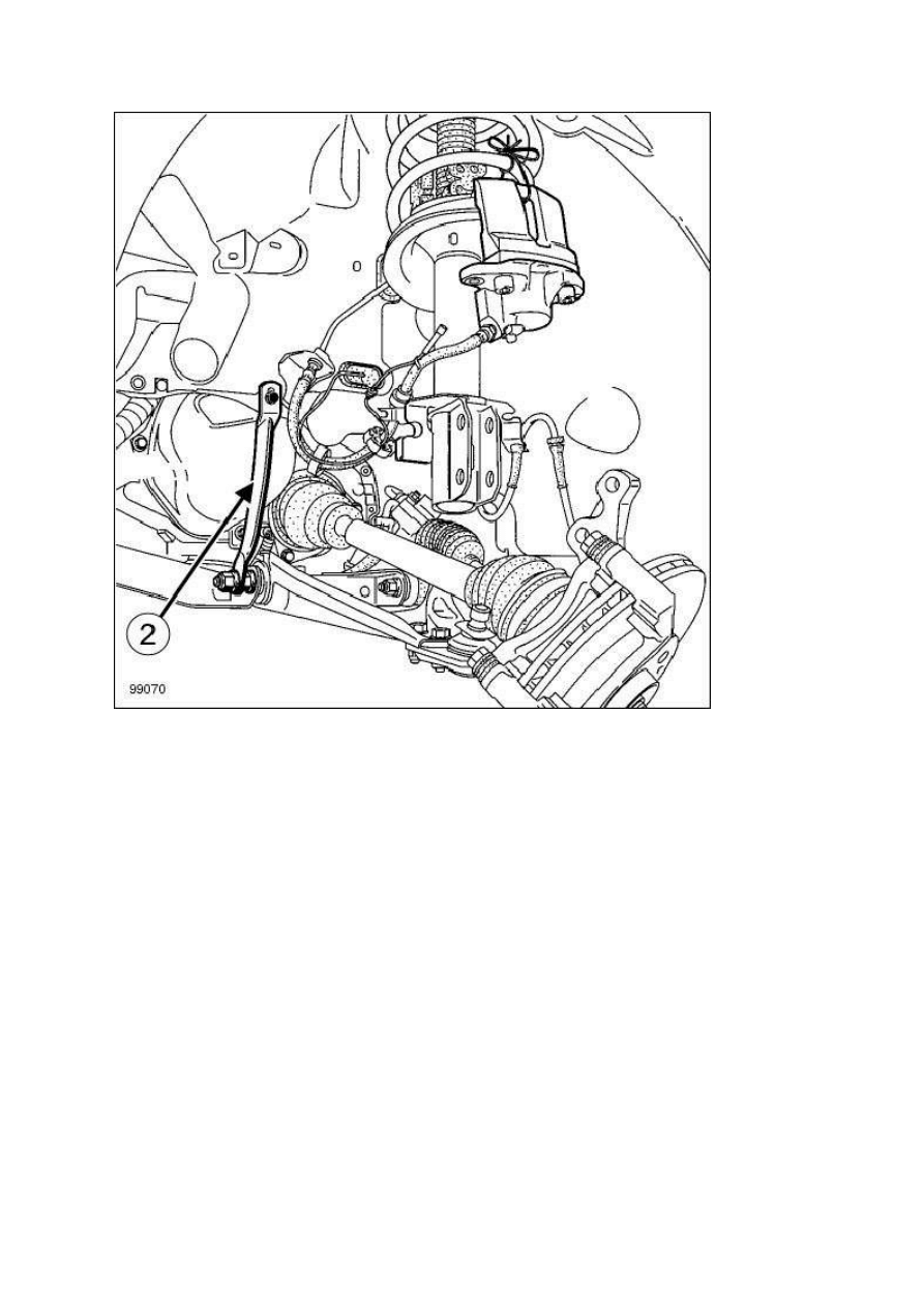
Remove on both sides:
The brake callipers, and hang them up
The ABS sensors
The track rod ends using the Ball joint extractor. (Tav. 476)
The shock absorber base bolts,
The subframe - side member tie-rods (2)
The anti-roll bar tie rod upper bolt (off-road vehicle only)
The "driveshaft - stub axle carrier" assembly
Check that the driveshaft rollers cannot be removed by hand. If they can, check if any of the needles
have fallen into the gearbox.
Remove the starter .
Disconnect:
The reversing light connector
The speedometer connector
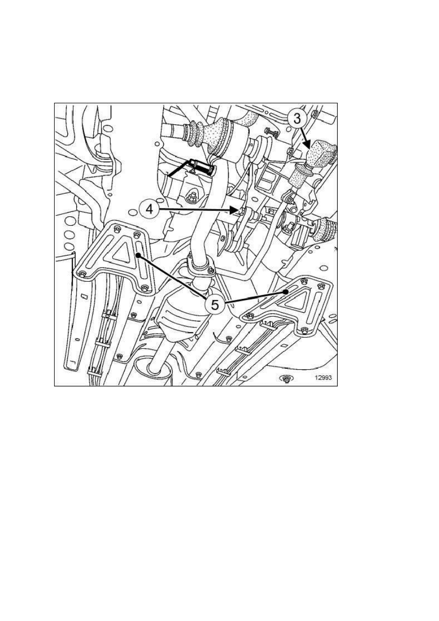
Remove:
The subframe tie-rods (5)
The tie-bar - gearbox mounting bolt (3)
The gear control linkage
The engine tie-bar bolt (4) on the gearbox
The gearbox rear support
The power-assisted steering pipe mountings (if fitted)
Remove the gearbox-engine strut.
If necessary, insert a shim to tilt the engine forward to facilitate removal of the steering rack.
Remove the steering mountings from the sub-frame.
Attach the vehicle steering.
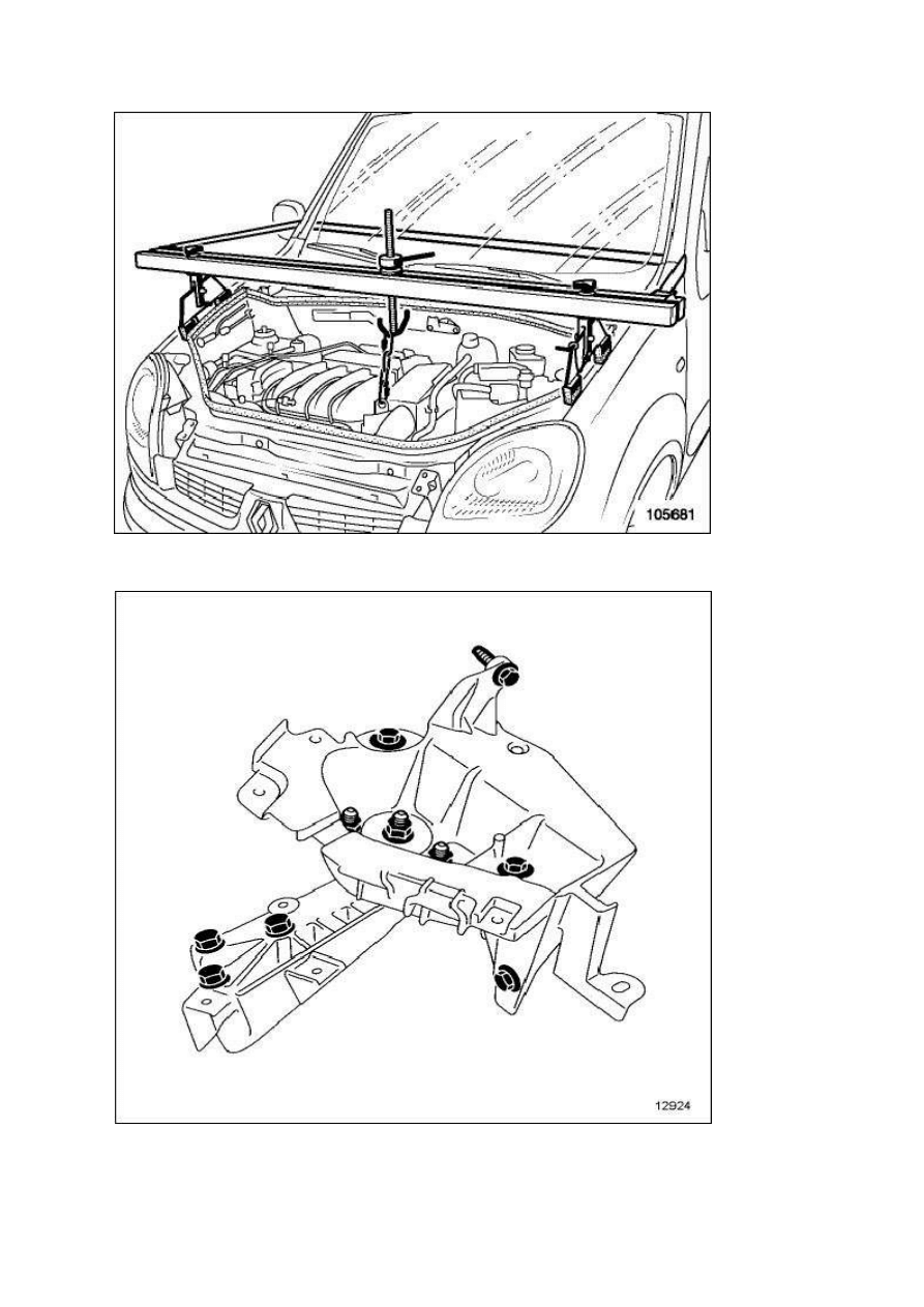
Position the Engine anchorage support with multiple adjustments and retaining straps. (Mot. 1453) .
Remove the gearbox support.
Fully lower the engine using the Engine anchorage support with multiple adjustments and retaining
straps. (Mot. 1453) .
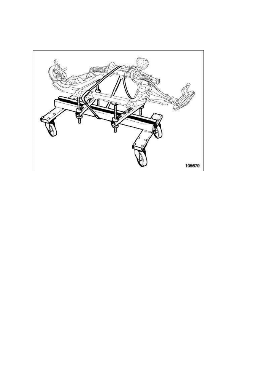
Position the Support for removal - refitting of engine - gearbox assembly (Mot. 1390) under the sub-
frame.
Adjust the pad height to ensure the sub-frame is stable on the tool.
Lower the final drive until the subframe is touching the Support for removal - refitting of engine -
gearbox assembly (Mot. 1390) .
WARNING
Strap the sub-frame to the Support for removal - refitting of engine - gearbox assembly (Mot. 1390) .
Remove:
The sub-frame mounting bolts
The subframe
Set up the component jack under the gearbox.
Remove the gearbox lower mounting bolts.
Separate the gearbox from the engine.
Remove the gearbox.

REFITTING
Proceed in the reverse order to removal.
Check that the centering rings are in place and correctly positioned.
Torque tighten:
The lower ball joint nut 62 N.m
The track rod end nut 40 N.m
The shock absorber base nut 180 N.m
The engine tie-bar bolt on the gearbox (K7J, F8Q and D7F) 62 N.m
The engine tie-bar bolt on the gearbox (D4F) 105 N.m
The engine tie-bar bolt on the gearbox (K9K and K4M) 110 N.m
The gearbox bell housing and starter bolts 45 N.m
The suspended mounting nuts on the gearbox 62 N.m
The driveshaft gaiter mounting bolts 25 N.m
Apply FRENBLOCto the steering box mounting bolts.
Torque tighten:
The steering box mounting bolts 50 N.m
The subframe front mounting bolts 62 N.m
The subframe rear mounting bolts 105 N.m
The subframe - side member tie-rod bolts 30 N.m
The subframe tie-rod bolts 21 N.m
The gear control tie-bar mounting bolts 28 N.m
Check that the clutch system is operating correctly.
Fill up the gearbox.
Connect the battery, starting with the positive terminal.
Wyszukiwarka
Podobne podstrony:
Installation Removal guide RUS
Guide for solubilization of membrane proteins and selecting tools for detergent removal
Hair Removal Complete Guide
guide camino aragones pl
Herbs for Sports Performance, Energy and Recovery Guide to Optimal Sports Nutrition
Meezan Banks Guide to Islamic Banking
NLP for Beginners An Idiot Proof Guide to Neuro Linguistic Programming
freespan spec guide
Eaton VP 33 76 Ball Guide Unit Drawing
Herbs to Relieve Headaches Keats Good Herb Guide
50 Common Birds An Illistrated Guide to 50 of the Most Common North American Birds
Configuration Guide WAN Access(V100R006C00 02)
installation guide
iR Shell 3 9 User Guide
1970 01 01 Kant039s 039perpetual peace039 utopia or political guide
M12 Oncore Users Guide Supplement
więcej podobnych podstron