
SUPPLY
166
Strona 1 z 7
eLearn - Packet print
2011/06/28
file://F:\alfa\eLearn\Web\tempschprint.html

SUPPLY - Description
The entire electrical system has been designed and constructed in accordance with the most up-to-date guidelines concerning safety and protection,
especially against fire risks.
There are two main kinds of protection:
active protection, aimed at reducing possible causes of faults 'at source';
passive protection, aimed at minimizing the effects of a possible fault.
The first kind involves the thoughtful design of wiring, attentive to location and anchorage, and the careful planning of properly protected cable
routes.
Modifications have therefore been made to the alternator and starter motor cables, with the adoption of protective caps, etc.
Passive protection instead includes all the interventions, which have always been adopted on vehicles, to reduce high fault currents (overload and
short circuit).
All the fuses included in the system have been rated on the basis of the nominal absorption of the loads which cannot be served simultaneously, and
so as to ensure intervention in the case of a definite short circuit.
All the electrical systems are supplied by the battery at a voltage of 12. V.
The battery is in turn recharged by the alternator ( E5010 STARTING AND RECHARING ) during engine operation.
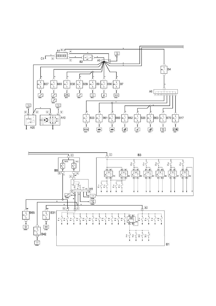
The main supply lines are protected by 'MAXIFUSES', grouped together in a container located in the engine compartment services compartment.
The power supplies to all services and systems are protected by fuses grouped in the junction units, one of which is inside the passenger
compartment and the other one which is in the engine compartment on the left side panel. The unattached fuses are located in the engine
compartment near the rear bulkhead and in compartments protected by covers in the luggage compartment, one on the right hand side and the
other on the left hand side behind the battery.
All the power supplies are thus protected, except for the starter motor cable (battery-starter motor) and recharging cable (starter motor-alternator):
these are protected by an additional shielded sheath.
Some circuits are supplied continuously, even if the vehicle is stopped and the ignition is off, as they are connected directly to the battery.
Other circuits are supplied by turning the ignition key to various different positions:
when the key is inserted and turned to the first click, the ignition is turned on (MAR position) and several circuits are supplied, which are thus
called 'ignition-operated' (lines 'INTE' and '15/54');
the second click - AVV (starting) position - supplies the starter motor (line '50'), disconnecting certain circuits (those which absorb greater
power) and thereby guaranteeing the maximum current flow to the actual starter motor; ('INT/A' line).
This general diagram shows all the lines which depart from the battery and the MAXIFUSE boxes; reference should be made to the specific diagrams
for greater detail.
The lines through which the supply is distributed to the various electrical devices are shown on the wiring diagrams relating to the various
functions and systems.
Strona 2 z 7
eLearn - Packet print
2011/06/28
file://F:\alfa\eLearn\Web\tempschprint.html

SUPPLY - Functional description
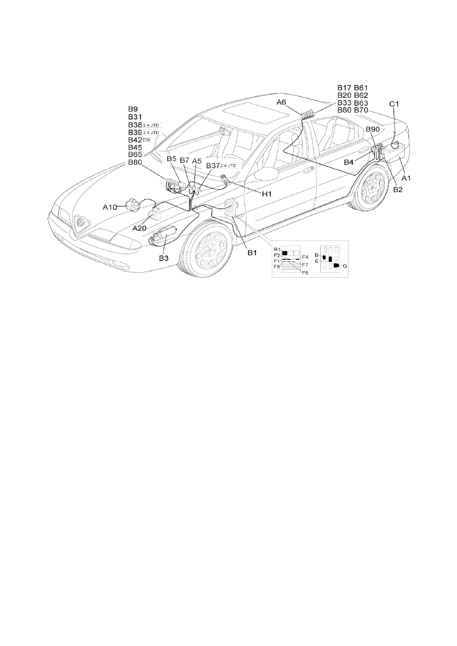
All electrical equipment and systems are supplied by battery A1, located in the boot compartment: two junction units distribute power to the various
parts of the car.
junction unit A6 is located at the rear. This is protected by MAXIFUSE for rear services B4 (60A). It sends power to all services with control
units or systems located in the boot compartment.
terminal board A5 is located at the front - in the engine bay. This is protected by master power supply MAXIFUSE B2 (125A). It sends power
to all services with control units or systems located in the engine bay.
The other supply lines leading to junction unit B1 and ignition switch H1 are protected by both MAXIFUSES B5:
ACC (30A) for supply to ignition switch H1 ;
CENTR (60A) for supply for services via fuses for junction unit B1
Other circuits are supplied by turning ignition key H1 to various different positions:
certain ignition-operated services are supplied when the key is turned to MAR;
in the AVV position - the starter motor is supplied; (line '50') (3309762SeeE5010STARTING AND RECHARING);
certain services which are ignition-operated except at start-up are disconnected in this position (INT/A line)
Strona 3 z 7
eLearn - Packet print
2011/06/28
file://F:\alfa\eLearn\Web\tempschprint.html
SUPPLY - Location of components
Component code
Name
Assembly reference
A1
Battery
5530B
A5
Terminal board
-
A6
Rear junction node
-
A10
Alternator
-
A10
Alternator
5530A
A20
Starter motor
-
A20
Starter' motor
5520B
B1
Junction unit
-
B1
Junction unit
5505A
B1
Junction unit
5505A
B2
Dashboard junction unit (CPL)
-
B2
General supply MAXI FUSE
-
B2
Junction unit
-
B2
Junction unit
5505A
B3
Relay unit
5505A
B4
Rear services MAXI FUSE
-
B5
MAXI FUSE box
-
B7
-MAXI FUSE) for ABS
-
B8
(MAXI FUSE) for engine fan
-
B9
Starting enablement MAXI FUSE
-
B17
Rear electric windows fuse
-
B20
Seat heating fuse
-
B31
ABS fuse
-
B33
Heated rear window fuse
-
B37
Spark plugs MAXI FUSE
-
B38
Additional heater fuse
-
B39
Diesel pre-heating fuse
-
B42
CAE supply fuse
-
B60
Boot opening fuse
-
B61
Fuel flap opening fuse
-
B62
Left seat adjustment fuse
-
B63
Right seat adjustment fuse
-
B65
Vehicle interior fan fuse
-
B70
Trailer fuse
-
B80
i.e. MAXI FUSE
-
B90
Radio amplifier fuse
-
B99
Battery fuses junction unit (CBA)
5530B
Strona 4 z 7
eLearn - Packet print
2011/06/28
file://F:\alfa\eLearn\Web\tempschprint.html

C1
Battery earth
-
C10
Front left earth
-
C31
Rear right earth
-
D1
Front-dashboard coupling
-
D6
Rear - front coupling
-
D19
Dashboard / battery coupling
-
H1
Ignition switch
5520A
I50
Inertial switch
1040A
M40
A.B.I control unit
5505A
N40
Fuel pump and sender unit
-
Strona 5 z 7
eLearn - Packet print
2011/06/28
file://F:\alfa\eLearn\Web\tempschprint.html
SUPPLY - Wiring diagram
Component code
Name
Assembly reference
A1
Battery
5530B
A5
Terminal board
-
A6
Rear junction node
-
A10
Alternator
-
A10
Alternator
5530A
A20
Starter motor
-
Strona 6 z 7
eLearn - Packet print
2011/06/28
file://F:\alfa\eLearn\Web\tempschprint.html

A20
Starter' motor
5520B
B1
Junction unit
-
B1
Junction unit
5505A
B1
Junction unit
5505A
B2
Dashboard junction unit (CPL)
-
B2
General supply MAXI FUSE
-
B2
Junction unit
-
B2
Junction unit
5505A
B3
Relay unit
5505A
B4
Rear services MAXI FUSE
-
B5
MAXI FUSE box
-
B7
-MAXI FUSE) for ABS
-
B8
(MAXI FUSE) for engine fan
-
B9
Starting enablement MAXI FUSE
-
B17
Rear electric windows fuse
-
B20
Seat heating fuse
-
B31
ABS fuse
-
B33
Heated rear window fuse
-
B37
Spark plugs MAXI FUSE
-
B38
Additional heater fuse
-
B39
Diesel pre-heating fuse
-
B42
CAE supply fuse
-
B60
Boot opening fuse
-
B61
Fuel flap opening fuse
-
B62
Left seat adjustment fuse
-
B63
Right seat adjustment fuse
-
B65
Vehicle interior fan fuse
-
B70
Trailer fuse
-
B80
i.e. MAXI FUSE
-
B90
Radio amplifier fuse
-
B99
Battery fuses junction unit (CBA)
5530B
C1
Battery earth
-
C10
Front left earth
-
C31
Rear right earth
-
D1
Front-dashboard coupling
-
D6
Rear - front coupling
-
D19
Dashboard / battery coupling
-
H1
Ignition switch
5520A
I50
Inertial switch
1040A
M40
A.B.I control unit
5505A
N40
Fuel pump and sender unit
-
Strona 7 z 7
eLearn - Packet print
2011/06/28
file://F:\alfa\eLearn\Web\tempschprint.html
Wyszukiwarka
Podobne podstrony:
elektro info 2007 05 projekt Rys3 Schemat zasilania RPJ
Narysować schemat zasilania instalacji elektrycznej nN
Schemat zasilacz
elektro info 2007 05 projekt Rys3 Schemat zasilania RPJ
schemat zasilacz
Schematy zasilania
RYS MAŁY, Schemat stacji energetycznej zasilaj˙cej zak˙ad przemys˙owy.
RYS1 2, Schemat stacji energetycznej zasilaj˙cej zak˙ad przemys˙owy.
MALRYS, Schemat stacji energetycznej zasilaj˙cej zak˙ad przemys˙owy.
RYSPRPLA, Schemat stacji energetycznej zasilaj˙cej zak˙ad przemys˙owy.
zasilacz schemat
Zasilacz schemat
Schemat ideowy zasilacza z SN1533 Ver 2 0
V640 Zasilacz do v640 schemat
Schemat złącza zasilania dysku ATA
więcej podobnych podstron