
This document is exclusive property of Cisco Systems, Inc. Permission is granted
to print and copy this document for non-commercial distribution and exclusive
use by instructors in the CCNA Exploration: Network Fundamentals course as
part of an official Cisco Networking Academy Program.

All contents are Copyright © 1992–2007 Cisco Systems, Inc. All rights reserved. This document is Cisco Public Information.
Page 1 of 5
Activity 1.1.1: Using Google Earth™ to View the World
Learning Objectives
Upon completion of this activity, you will be able to:
•
Explain the purpose of Google Earth.
•
Explain the different versions of Google Earth.
•
Explain the hardware and software requirements needed to use Google Earth (free edition).
•
Experiment with Google Earth features such as Help | Tutorial.
•
Experiment with Google Earth to explore continents, countries, and places of interest.
Background
Google Earth is a popular application that executes on the desktop of most operating systems. It requires
a broadband connection to the Internet and displays Earth as a manipulated 2D, or 3D image. The
popular world news channel, CNN, regularly uses Google Earth to emphasize where a news story has
occurred.
At the time of writing this activity, there are three versions of Google Earth. The version that fits most
needs is Google's free version, Google Earth. A Google Earth Plus version includes GPS support, a
spreadsheet importer, and other support features. The Google Earth Pro version is for professional and
commercial use. The URL
http://earth.google.com/product_comparison.html
contains a description of the
versions. Use this link to answer the following questions:
Which versions support Tilt and 3D rotation? __________________________
Which Google Earth version supports the highest resolution? __________________________
To use Google Earth, version 4, minimum computer hardware requirements must be met:
Operating System
Microsoft Windows 2000 or Windows XP
CPU
Pentium 3 with 500 MHz
System Memory (RAM)
128 MB
Hard Disk
400 MB of free space
Network Speed
128 kbps
Graphics Card
3D-capable with 16 MB of VRAM
Screen
1024x768 pixels, 16-bit High Color screen
Scenario
This activity is to be performed on a computer that has Internet access and on which you can install
software.
Estimated completion time, depending on network speed, is 30 minutes.

CCNA Exploration
Network Fundamentals:
Living in a Network-Centric World
Activity 1.1.1: Using Google Earth™ to View the World
All contents are Copyright © 1992–2007 Cisco Systems, Inc. All rights reserved. This document is Cisco Public Information.
Page 2 of 5
Task 1: Install Google Earth.
If Google Earth is not installed on the computer, the free application can be downloaded directly from
http://earth.google.com/download-earth.html
. Follow the installation instructions, and the Google Earth
download should start automatically. Remember, you may have to disable any popup blockers on your
browser.
Figure 1. Google Earth Opening Screen
Task 2: Run Google Earth.
Step 1: Refer to Figure 1, the opening screen. The Menu bar is located in the upper left corner of the
screen. On the Help menu, choose User Guide to launch a default web browser and bring up the Google
Earth User’s Guide.
http://earth.google.com/userguide/v4/
. Take a few minutes to browse the User’s
Guide. Before leaving the User’s Guide web site, answer the following questions:
List the three ways to move the image.
__________________________________________
__________________________________________
__________________________________________
Which mouse control will zoom in or zoom out?
__________________________________________
What is the purpose of the left mouse button?
__________________________________________
Task 3: Navigatie the Google Earth Interface.
Step 1: Use the Overview Map feature.
On the View menu, choose Overview Map. This handy feature provides a relative global position of the
magnified image.

CCNA Exploration
Network Fundamentals:
Living in a Network-Centric World
Activity 1.1.1: Using Google Earth™ to View the World
All contents are Copyright © 1992–2007 Cisco Systems, Inc. All rights reserved. This document is Cisco Public Information.
Page 3 of 5
Step 2: Review the navigation controls.
Navigation controls are located in the upper right quadrant and control the image magnification and
position. The mouse pointer must be moved close to the controls, otherwise only a compass is displayed.
Refer to Figure 2 for a description of the navigation controls.
Figure 2. Google Earth Screen Navigation Tools
Step 3: Use the Sightseeing feature.
On the left navigation bar, experiment with the Places > Sightseeing folder. Expand Sightseeing, choose
a location that you would like to see, and double-click that location. The image will take you to that site.
When the location has been reached, an image streaming indicator reports when the image resolution is
complete.
Step 4: Experiment with the Search > Fly To folder.
Enter 95134, a U.S. Zip Code.
What U.S. State and City are displayed? ________________
What if you would like to "Fly To" London, UK? What data would you need to enter?
____________________________________________________________________________
____________________________________________________________________________
Step 5: Use the Fly To feature.
Some locations have better resolution than others, and some location images are older than others. For
example, one user commented that he found his home, but the new home next door had not yet been
built. Try to find your home using the Search > Fly To folder.
Is the resolution for your home the same quality as the Sightseeing location in Step 3? _______________
If the resolution for your neighborhood is sufficient, browse the surrounding area to see if you can
determine approximately how old the image is.

CCNA Exploration
Network Fundamentals:
Living in a Network-Centric World
Activity 1.1.1: Using Google Earth™ to View the World
All contents are Copyright © 1992–2007 Cisco Systems, Inc. All rights reserved. This document is Cisco Public Information.
Page 4 of 5
Figure 3. World Map with Latitude and Longitude Lines
Step 6: View geographic coordinates.
Geographic coordinates are displayed in the lower left quadrant of the image. The first number is called
the latitude, and is the angle between a point and the equator. For example, the equator is an imaginary
line dividing the globe into the Northern or Southern Hemisphere. The equator has a 0
o
latitude. The
second number is called the longitude, and is the angle east or west of an arbitrary earth point. The Royal
Observatory, United Kingdom, is the international zero-longitude point. The combined longitude and
latitude is called the common graticule. The coordinate measurements are in degrees
o
,
minutes’,
seconds, and tenths". For latitude, the reference is North (N) or South (S) of the equator. For longitude,
the reference is East (E) or West (W) of the Royal Observatory. Refer to Figure 3. For a layman’s
definition of geographic coordinates, go to URL
http://en.wikipedia.org/wiki/Geographic_coordinate_system
. On the View menu, choose Grid to display
Google Earth Gridlines.
Using the pointer and coordinates shown in the lower left quadrant of the image, what are the coordinates
of your home? ____________________________
Task 4: Reflection
Google Earth can bring the world into the home or office. While enjoying the images, consider what digital
communication resources were used. For example, satellite communication with an earth station
transmitted the image of your home to a ground location. Some type of database was used to store the
image. A Local Area Network (LAN) sent your image request across the Internet, probably through
several Wide Area Networks (WANs) and then to another LAN with a computer that returned the image to
you. The delay in retrieving the image may have been short or long, depending on the slowest speed of
all network connections in the path between the database repository and your computer.
Could the image be displayed faster if data compression techniques were used?
Consider network security. Could someone eavesdrop on your network connection?

CCNA Exploration
Network Fundamentals:
Living in a Network-Centric World
Activity 1.1.1: Using Google Earth™ to View the World
All contents are Copyright © 1992–2007 Cisco Systems, Inc. All rights reserved. This document is Cisco Public Information.
Page 5 of 5
Task 5: Challenge
Google Earth displays image coordinates in the lower left quadrant of the image. Use the following URL
to learn about different coordinate systems:
http://www.colorado.edu/geography/gcraft/notes/coordsys/coordsys.html
. Wikipedia contains a useful
definition of common geographical terms.
Use the geographic coordinate system to describe your home with as much accuracy and detail as
possible.
Task 6: Clean Up
You may be required to remove Google Earth from the computer. If so, perform these steps:
1. Click Start > Settings > Control Panel.
2. Double-click Add or Remove Programs.
3. Locate and click Google Earth.
4. Click Remove and follow the prompts.
Additional removal information is available from URL
http://earth.google.com/support/bin/answer.py?answer=20738&ctx=sibling.
Unless instructed otherwise, turn off the computer.

All contents are Copyright © 1992–2007 Cisco Systems, Inc. All rights reserved. This document is Cisco Public Information.
Page 1 of 4
Activity 1.4.5: Identifying Top Security Vulnerabilities
Learning Objectives
Upon completion of this activity, you will be able to:
•
Use the SANS site to quickly identify Internet security threats.
•
Explain how threats are organized.
•
List several recent security vulnerabilities.
•
Use the SANS links to access other security-related information.
Background
One of the most popular and trusted sites related to defending against computer and network security
threats is SANS. SANS stands for SysAdmin, Audit, Network, Security. SANS contains several
components, each a major contributor to information security. For additional information about the SANS
site, go to http://www.sans.org/, and select items from the Resources menu.
How can a corporate security administrator quickly identify security threats? SANS and the FBI have
compiled their list of the top 20 Internet Security Attack Targets at http://www.sans.org/top20/. The list is
regularly updated with information formatted by:
•
Operating Systems—Windows, Unix/Linux, MAC
•
Applications—Cross-platform, including web, database, Peer-to-Peer, instant messaging, media
players, DNS servers, backup software, and management servers
•
Network Devices—Network infrastructure devices (routers, switches, etc.), VoIP devices
•
Human Elements—Security policies, human behavior, personnel issues
•
Special Section—Security issues not related to any of the above categories
Scenario
This lab will introduce students to computer security issues vulnerabilities. The SANS web site will be
used as a tool for threat vulnerability identification, understanding, and defense.
This lab must be completed outside of the Cisco lab from a computer with Internet access.
Estimated completion time is one hour.

CCNA Exploration
Network Fundamentals:
Living in a Network-Centric World
Activity 1.4.5 Identifying Top Security Vulnerabilities
All contents are Copyright © 1992–2007 Cisco Systems, Inc. All rights reserved. This document is Cisco Public Information.
Page 2 of 4
Task 1: Locate the SANS Resources.
Step 1: Open the SANS Top 20 List.
Using a web browser, go to URL http://www.sans.org. On the resources menu, choose top 20 list,
shown in Figure 1.
Figure 1. SANS Menu
The SANS Top-20 Internet Security Attack Targets list is organized by category. An identifying letter
indicates the category type, and numbers separate category topics. Router and switch topics fall under
the Network Devices category, N. There are two major hyperlink topics:
N1. VoIP Servers and Phones
N2. Network and Other Devices Common Configuration Weaknesses
Step 2: Click hyperlink N2. Network and Other Devices Common Configuration Weaknesses to
jump to this topic.
Task 2: Review the SANS Resources.
Step 1: Review the contents of N2.2 Common Default Configuration Issues.
For example, N.2.2.2 (in January 2007) contains information about threats associated with default
accounts and values. A Google search on “wireless router passwords” returns links to multiple sites that
publish a list of wireless router default administrator account names and passwords. Failure to change the
default password on these devices can lead to compromise and vulnerability by attackers.
Step 2: Note the CVE references.
The last line under several topics references Common Vulnerability Exposure (CVE). The CVE name is
linked to the National Institute of Standards and Technology (NIST) National Vulnerability Database
(NVD), sponsored by the Department of Homeland Security (DHS) National Cyber Security Division and
US-CERT, which contains information about the vulnerability.

CCNA Exploration
Network Fundamentals:
Living in a Network-Centric World
Activity 1.4.5 Identifying Top Security Vulnerabilities
All contents are Copyright © 1992–2007 Cisco Systems, Inc. All rights reserved. This document is Cisco Public Information.
Page 3 of 4
Task 3: Collect Data.
The remainder of this lab walks you through a vulnerability investigation and solution.
Step 1: Choose a topic to investigate, and click on an example CVE hyperlink.
Note: Because the CVE list changes, the current list may not contain the same vulnerabilities as those in
January 2007.
The link should open a new web browser connected to http://nvd.nist.gov/ and the vulnerability summary
page for the CVE.
Step 2: Fill in information about the vulnerability:
Original release date: ____________________________
Last revised: ___________________________________
Source: _______________________________________
Overview:
____________________________________________________________________________
____________________________________________________________________________
____________________________________________________________________________
____________________________________________________________________________
____________________________________________________________________________
Under Impact, there are several values. The Common Vulnerability Scoring System (CVSS) severity is
displayed and contains a value between 1 and 10.
Step 3: Fill in information about the vulnerability impact:
CVSS Severity: ________________________
Range: _______________________________
Authentication: _________________________
Impact Type: __________________________
The next heading contains links with information about the vulnerability and possible solutions.
Step 4: Using the hyperlinks, write a brief description of the solution as found on those pages.
____________________________________________________________________________________
____________________________________________________________________________________
____________________________________________________________________________________
____________________________________________________________________________________
____________________________________________________________________________________
____________________________________________________________________________________
____________________________________________________________________________________
____________________________________________________________________________________

CCNA Exploration
Network Fundamentals:
Living in a Network-Centric World
Activity 1.4.5 Identifying Top Security Vulnerabilities
All contents are Copyright © 1992–2007 Cisco Systems, Inc. All rights reserved. This document is Cisco Public Information.
Page 4 of 4
Task 4: Reflection
The number of vulnerabilities to computers, networks, and data continues to increase. The governments
have dedicated significant resources to coordinating and disseminating information about the vulnerability
and possible solutions. It remains the responsibility of the end user to implement the solution. Think of
ways that users can help strengthen security. Think about user habits that create security risks.
____________________________________________________________________________________
____________________________________________________________________________________
____________________________________________________________________________________
____________________________________________________________________________________
____________________________________________________________________________________
____________________________________________________________________________________
____________________________________________________________________________________
____________________________________________________________________________________
____________________________________________________________________________________
____________________________________________________________________________________
Task 5: Challenge
Try to identify an organization that will meet with us to explain how vulnerabilities are tracked and
solutions applied. Finding an organization willing to do this may be difficult, for security reasons, but will
benefits students, who will learn how vulnerability mitigation is accomplished in the world. It will also give
representatives of the organization an opportunity to meet the class and conduct informal intern
interviews.

Lab 1.6.1: Using Collaboration Tools— IRC and IM
Topology Diagram
Learning Objectives
Upon completion of this lab, you will be able to:
• Define Internet Relay Chat (IRC) and Instant Messaging (IM).
• List several collaborative uses of IM.
• List several misuses and data security issues involving IM.
• Use IRC to demonstrate collaboration.
Background
E-mail permits multiple users to collaborate, share ideas, and transfer files. However, unless the user
constantly monitors the e-mail account, unread e-mail may go unnoticed for a long period of time. When
people have wanted immediate contact, the telephone has been the technology of choice. Unfortunately,
the telephone cannot be used to transfer files. What collaborators need for communication in the human
network is a tool that has the flexibility of e-mail with the responsiveness of the telephone. Internet Relay
Chat (IRC) and Instant Messaging (IM) fit nicely into these requirements. Using the Internet or a private
corporate network, users can easily exchange ideas and files. IMing and Chatting are both methods of
real-time communication; however, they are implemented differently.
Instant Messaging provides one-on-one communication with "accepted" individuals. To initiate an Instant
Message, one person needs to "invite" another. The recipient of the invitation needs to know—and
accept—the IM session based on the other user's screen name. IM clients allows you to have an
approved list of users, often called a Buddy List. If you want to communicate with more than one person
at a time, you can open additional IM windows. Each of these windows represents a two-person
communication.
Internet Relay Chat, on the other hand, allows multiple people to interact. Chat also provides a degree of
anonymity. To start chatting, you establish a connection to a chat server and join a discussion on a
particular topic. When you join, you are said to “join a room.” In the chat room, you typically create your
own identity and can give as little information about yourself as you choose.
While the following discussion focuses primarily on IM, a brief hands-on lab with our “model Internet
cloud” will demonstrate the ease of IRC.
IM requires a device providing services that allows users to communicate. This device is referred to as
the Instant Messenger Server. The users on the end devices, such as a computer, use a piece of
software called the Instant Messenger Client. This arrangement is called a client/server relationship. IM
All contents are Copyright © 1992–2007 Cisco Systems, Inc. All rights reserved. This document is Cisco Public Information.
Page 1 of 7

CCNA Exploration
Network Fundamentals:
Living in a Network-Centric World
Lab 1.6.1: Using Collaboration Tools— IRC and IM
clients connect to an IM server, and the server joins clients. This relationship is called an IM network.
There are many different IM networks available, each with a dedicated following of users. Popular IM
networks include America On Line (AOL) Instant Messenger (AIM), Windows Live Messenger (MSN),
Yahoo! Messenger, and ICQ (I Seek You). Figure 1 shows the AIM client application connected to the
AIM network.
Figure 1. AIM Client
Features
IM services have several common features:
• When an IM client connects to the IM network, any existing connections can be alerted through a
contact list, a list of other people that you communicate with through the IM Client.
• File sharing between IM clients enables work collaboration.
• Text messaging between clients is possible, and can be logged.
• Some IM networks offer audio services.
• Newer services that some IM networks are beginning to provide include video conferencing,
Voice over IP (VoIP), web conferencing, desktop sharing, and even IP radio and IPTV.
Protocols
Each IM network uses an agreed-upon method of communication, called a protocol. Many of the IM
networks use proprietary protocols. AIM and ICQ (purchased by AOL) use the proprietary Open System
for Communication in Realtime (OSCAR) protocol. Both Microsoft and Yahoo! have proprietary protocols
but have partnered services for joint connectivity.
Throughout this course we will learn about many different protocols. The Internet Engineering Task Force
(IETF) has attempted to standardize IM protocols, notably with the Session Initialization Protocol (SIP).
SIPv2 was originally defined in RFC 2543, and made obsolete by RFC 3261. As with proprietary IM
protocols, there are numerous open source protocols.
Some IM client applications, such as Gaim and Trillian, can differentiate between the various IM network
protocols; IM servers can also incorporate this support. The IETF formalized an open standard, Jabber,
based on the Extensible Messaging and Presence Protocol (EMPP). Applicable IETF references are RFC
3290 and RFC 3291. Encrypted communication is supported.
All contents are Copyright © 1992–2007 Cisco Systems, Inc. All rights reserved. This document is Cisco Public Information.
Page 2 of 7

CCNA Exploration
Network Fundamentals:
Living in a Network-Centric World
Lab 1.6.1: Using Collaboration Tools— IRC and IM
Social misuse of IM has been a concern for parents, and many IM networks encourage parental control.
Child restrictions include limiting IM contacts and providing supervision while online. AIM and Yahoo!
Messenger provide free supervision software tools. Some parental supervision tools include background
logging, online time limits, chat room blocking, blocking specific users, and disabling certain functions of
the client.
Security
Multiple security issues have been identified with IM. As a result, many organizations either limit or
completely block IM from entering the corporate network. Computer worms, viruses, and Trojan horses,
categorized as malware, have been transferred to IM client computers. Without strong security methods,
information exchanged between users can be captured and disclosed. IM clients and IM servers have
experienced application vulnerabilities, which have resulted in vulnerable computers. Even legitimate
users can congest network throughput by transferring large files.
How does a system administrator protect his or her network from IM vulnerabilities and misuse? The
SysAdmin, Audit, Network, Security (SANS) Institute recommends several countermeasures. The
following list is from the SANS web site, http://www.sans.org/top20/#c4:
C4.4 How to Protect against IM Vulnerabilities and Unauthorized IM Usage
• Establish policies for acceptable use of IM. Ensure that all users are aware of those policies
and clearly understand the potential risks.
• Standard users should not be permitted to install software. Restrict Administrative and Power
User level privileges to support personnel acting in their support capacity. If a user must have
Administrative or Power User privileges, create a separate account to be used for his or her
daily office functions, Internet surfing, and online communication.
• Ensure that vendor patches are promptly applied to IM software, interrelated applications,
and the underlying operating system.
• Employ antivirus and antispyware products.
• Do not rely on external IM servers for internal use of IM; provide a commercial grade IM
proxy or internal IM server.
• Create secure communication paths when using IM with trusted business partners.
• Appropriately configure intrusion detection and prevention systems. Understand that many IM
applications are capable of enabling associated communications to masquerade as otherwise
legitimate traffic (for example, http).
• Consider deploying products specifically designed for IM security.
• Filter all http traffic through an authenticating proxy server to provide additional capabilities of
filtering and monitoring IM traffic.
• Block access to known public IM servers that have not been explicitly authorized. (Note: This
offers only partial protection due to the number of potential external servers.)
• Block popular IM ports. (Note: This offers only partial protection, due to the number of
potential protocols and associated ports, and the ability of applications to bypass port
restrictions.)
• Monitor using an Intrusion Detection/Prevention system for users creating tunnels for IM or
bypassing proxies.
The Future of IM
The future of IM is promising, enabling users to adapt new technologies for collaboration. For example,
mobile IM supports mobile users, providing IM services to hand-held cellular phones. Most popular
cellular phone manufacturers have their own form of mobile IM. Another popular hand-held appliance is
the Blackberry. The Blackberry supports common IM tools, such as text messaging, as well as push e-
mail, telephony, and web browsing.
All contents are Copyright © 1992–2007 Cisco Systems, Inc. All rights reserved. This document is Cisco Public Information.
Page 3 of 7

CCNA Exploration
Network Fundamentals:
Living in a Network-Centric World
Lab 1.6.1: Using Collaboration Tools— IRC and IM
Scenario
The topology diagram shows two computers connected to a “cloud.” In networking, a cloud is often used
to symbolize a more complex network, such as the Internet, which is not the current focus of this
discussion. In this lab, you will use two computers that must first obtain communication software from the
network cloud. After installing the software, the cloud will still be necessary to provide communication
services. In subsequent chapters you will study in great detail the devices and protocols that are inside
the cloud. Inside the cloud is a server called eagle-server as well as other networking devices. This lab
uses eagle-server as the IRC server, and Gaim as the IRC client. Gaim is used for this lab, but any IRC
client may be used if available. An IRC client is available for download from eagle-server, URL
http://eagle-server.example.com/pub.
Estimated completion time is 45 minutes.
Task 1: Configuring the Chat Client
The IRC protocol is an open standard, originally described in RFC 1459, communicating across plain text
links.
Step 1: Verify that there is an IRC client on the lab computer.
If not, download and install gaim-1.5.0.exe (windows executable) from URL
server.example.com/pub/eagle_labs/eagle1/chapter1
. Accept the default settings during the
installation. After verifying that the Gaim chat client is installed, use the following steps to configure Gaim:
Step 2: Open Accounts window.
1. Open Gaim and select the Login window, icon Accounts. The Accounts window is shown in
Figure 2.
Figure 2. Gaim Accounts Window
2. On the Accounts window, click Add.
Step 2: Add a new account.
1. See Figure 3. On the Add Account window, expand the “Show more options” option. Fill in
required information:
Protocol: IRC
Screen Name: (how others will know you)
Server: eagle-server.example.com
Proxy Type: No Proxy
All contents are Copyright © 1992–2007 Cisco Systems, Inc. All rights reserved. This document is Cisco Public Information.
Page 4 of 7

CCNA Exploration
Network Fundamentals:
Living in a Network-Centric World
Lab 1.6.1: Using Collaboration Tools— IRC and IM
Figure 3. Gaim Add Account Window
2. When finished, click Save.
3. Close the Accounts window.
Task 2: Connection to Chat Server
Step 1: Sign On.
Return to the Login window, where the new account to eagle-server should be visible. Click Sign-on. Two
windows should open. Figure 4 shows the IRC connect status window. Figure 5 shows the main Gaim IM
client window, used for chatting or IM.
Figure 4. IRC Connect Status Window
All contents are Copyright © 1992–2007 Cisco Systems, Inc. All rights reserved. This document is Cisco Public Information.
Page 5 of 7

CCNA Exploration
Network Fundamentals:
Living in a Network-Centric World
Lab 1.6.1: Using Collaboration Tools— IRC and IM
Figure 5. Gaim IRC Client Window
Step 2: Join the Chat.
When the IRC client connects to the IRC server, the status window closes and a Buddy List window
displays. Click Chat, as shown in Figure 6.
Note: To join a chat channel, the Channel name must start with #. If the Channel name is incorrect, you
will be in a chat room alone (unless other students made a similar error).
Figure 6. Joining a Chat
Task 3: The Chat Session
Figure 7 shows a brief chat between users Root and student2. Multiple students can join and interact with
each other.
All contents are Copyright © 1992–2007 Cisco Systems, Inc. All rights reserved. This document is Cisco Public Information.
Page 6 of 7

CCNA Exploration
Network Fundamentals:
Living in a Network-Centric World
Lab 1.6.1: Using Collaboration Tools— IRC and IM
Figure 7. Participating in Chat
During the chat, consider how you—as a parent or network administrator—would manage this type of
connection.
Task 4: Reflection
On a network with an Internet connection, the Gaim IM client can be used to connect to several different
IM providers. Most teenagers and young adults today are familiar with IMing between friends and sharing
files, but the communication between the client and server may not be understood. As a future network
engineer, you should understand the social and security issues with IM and IRC.
Task 5: Challenge
While you are connected in chat, transfer files between partners. Use a continuous ping from the host to
the eagle server to monitor network throughput. Observe the response time before and during the file
transfer. Write a brief description of the network response time—during file transfers and without file
transfers.
_____________________________________________________________________
_____________________________________________________________________
_____________________________________________________________________
_____________________________________________________________________
_____________________________________________________________________
Task 6: Clean Up
Check with your instructor before removing Gaim and shutting down the computer.
All contents are Copyright © 1992–2007 Cisco Systems, Inc. All rights reserved. This document is Cisco Public Information.
Page 7 of 7

Lab 1.6.2: Using Collaboration Tools—Wikis and Web Logs
Topology Diagram
Learning Objectives
Upon completion of this lab, you will be able to:
• Define the terms wiki and blog.
• Explore wiki features.
Background
The lab topology should be configured and ready for use. If there are connectivity issues with the lab
computer connecting to Eagle Server, ask the instructor for assistance.
The topology diagram shows two computers connected to a “cloud.” In networking, a cloud is often used
to symbolize a more complex network that is not the current focus of discussion. In this lab, you will use a
host computer that connects across the cloud to access a Twiki. In subsequent chapters you will study in
great detail the devices and protocols that are inside the cloud.
Scenario
In this lab, you will have the opportunity to learn about the different parts of a wiki. If you ever used
Wikipedia, you are probably already familiar with the look and feel of a wiki. After using Wikipedia, with its
rich content and flexible links, moving back to flat files may feel constricting and unsatisfying.
To gain experience with a wiki, the TWiki wiki server installed on Eagle Server will be explored.
Task 1: Define the Terms Wiki and Blog.
Wikis
“Wiki” is a Hawaiian-language word that means fast. In networking terms, a wiki is a web-based
collaboration tool that permits almost anyone to immediately post information, files, or graphics to a
common site for other users to read and modify. A wiki enables a person to access a home page (first
page) that provides a search tool to assist you in locating the articles that interest you. A wiki can be
installed for the internet community or behind a corporate firewall for employee use. The user not only
reads wiki contents but also participates by creating content within a web browser.
All contents are Copyright © 1992–2007 Cisco Systems, Inc. All rights reserved. This document is Cisco Public Information.
Page 1 of 7

CCNA Exploration
Network Fundamentals:
Living in a Network-Centric World
Lab 1.6.2: Using Collaboration Tools—Wikis and Web Logs
Although many different wiki servers are available, the following common features that have been
formalized into every wiki:
• Any web browser can be used to edit pages or create new content.
• Edit and auto links are available to edit a page and automatically link pages. Text formatting is similar
to creating an e-mail.
• A search engine is used for quick content location.
• Access control can be set by the topic creator, defining who is permitted to edit content.
• A wiki web is a grouping of pages with different collaboration groups.
For more information on Wiki, visit the following URLs outside of class:
http://www.wiki.org/wiki.cgi?WhatsWiki
http://www.wikispaces.com/
Blogs
A web log, called a blog, is similar to a wiki in that users create and post content for others to read. Blogs
are normally the creation of a single person and the blog owner controls blog content. Some blogs permit
users to leave comments and provide feedback to the author while others are more restrictive. Free
internet blog hosting is available, similar to a free web site or e-mail account, such as www.blogger.com.
Task 2: Explore Wiki Features with Twiki Tutorial.
The Twiki tutorial consists of exploring some of the more common features of a wiki. Listed below are the
major topics covered in the tutorial:
20-Minute TWiki Tutorial
1. Get set...
2. Take a quick tour...
3. Open a private account…
4. Check out TWiki users, groups.
5. Test the page controls...
6. Change a page, and create a new one...
7. Use your browser to upload files as page attachments...
8. Get e-mail alerts whenever pages are changed...
As each topic in the tutorial is investigated, complete the questions in this task. The exception is “3. Open
a private account…”. Twiki requires email verification for new accounts, and email has not been
configured on the lab host computers. Instead, users have already been created for steps that require
login privileges.
The power of a wiki is in the rich hyperlink content. Following hyperlinks can present continuity problems.
It is recommended to open two browsers. Point one browser at the Twiki URL, and use the other browser
for ‘working’ pages. Adjust the browser window sizes so that instructions can be viewed in one browser
while actions can be performed in the other. Any external links that are selected will result in an error.
Step 1: Establish a web client connection to Eagle Server wiki.
Open a web browser and connect to the TWiki Sandbox, URL
server.example.com/twiki/bin/view/Sandbox/WebHome
. The URL name is case sensitive, and must be
typed exactly as shown. The Sandbox is a web topic designed to test wiki features. Refer to Figure 1.
All contents are Copyright © 1992–2007 Cisco Systems, Inc. All rights reserved. This document is Cisco Public Information.
Page 2 of 7

CCNA Exploration
Network Fundamentals:
Living in a Network-Centric World
Lab 1.6.2: Using Collaboration Tools—Wikis and Web Logs
Figure 1. TWiki Sandbox Web.
Step 2: Open the TWiki Tutorial.
Click the TWiki Tutorial link, highlighted in the red oval in Figure 1, to open the wiki tutorial page.
Step 3: Complete the TWiki tutorial.
Refer to the tutorial, step 1, “Get set... “, and step 2, “Take a quick tour...”. After completing
the first two tutorial sections, answer the following questions:
What is a WikiWord?
_________________________________________________________________
___________________________________________________________________
___________________________________________________________________
How many results are returned from a search of WebSearch? __________
Refer to the tutorial, step 3, “Open a private account…”. Email is not possible at this time, therefore
you will not be able to register. Instead, userids have been created for you to use later in this lab.
The key point to understand about this step is that registration is a two-part process. First, users fill in
registration information and submit the form to TWiki.
List the mandatory information required for registration:
_____________________________________________________________________
_____________________________________________________________________
_____________________________________________________________________
_____________________________________________________________________
_____________________________________________________________________
_____________________________________________________________________
_____________________________________________________________________
All contents are Copyright © 1992–2007 Cisco Systems, Inc. All rights reserved. This document is Cisco Public Information.
Page 3 of 7

CCNA Exploration
Network Fundamentals:
Living in a Network-Centric World
Lab 1.6.2: Using Collaboration Tools—Wikis and Web Logs
TWiki responds to a registration request by sending an email to the user that contains a unique activation
code.
The second part of the registration process is when the user (1) enters the code in the activation window,
or (2) responds with email by clicking on the TWiki response link. At this time, the user account is added
to the TWiki datatbase.
Refer to the tutorial, step 4, “Check out TWiki users, groups.”. A list of TWiki users and groups is
displayed. After completing this tutorial section, answer the following questions related to user and group
issues:
How is a user’s password reset?
_____________________________________________________________________
_____________________________________________________________________
_____________________________________________________________________
How can inappropriate changes be fixed in a wiki topic?
_____________________________________________________________________
Tutorial step 5, “Test the page controls...”, will familiarize you with page editing commands. After
completing this tutorial section, answer the following questions:
What is the latest revision number?
______________
Place the correct action link next to the description for page controls:
Attach
Backlinks
Edit
History
More Printable
r3 > r2 > r1
Raw View
Description Action
Link
add to or edit the topic
show the source text without editing the
topic
attach files to a topic
find out what other topics link to this
topic (reverse link)
additional controls, such as rename /
move, version control and setting the
topic's parent.
topics are under revision control- shows
the complete change history of the topic.
For example, who changed what and
when.
view a previous version of the topic or
the difference between two versions
goes to a stripped down version of the
page, good for printing
:
Tutorial step 6, “Change a page, and create a new one...“, is an opportunity for you to add
content to the wiki. Complete this tutorial, using the table below to login to the wiki server.
All contents are Copyright © 1992–2007 Cisco Systems, Inc. All rights reserved. This document is Cisco Public Information.
Page 4 of 7

CCNA Exploration
Network Fundamentals:
Living in a Network-Centric World
Lab 1.6.2: Using Collaboration Tools—Wikis and Web Logs
On Eagle Server a group with private accounts has been created to allow participation in a private TWiki
topic. These accounts are StudentCcna1 through StudentCcna22. All accounts have the same
password, cisco. You should use the account that reflects your pod and host computer number. Refer to
the following table:
Lab pod#host#
Account Login ID
(case sensitive)
Pod1host1
StudentCcna1
Pod1host2
StudentCcna2
Pod2host1
StudentCcna3
Pod2host2
StudentCcna4
Pod3host1
StudentCcna5
Pod3host2
StudentCcna6
Pod4host1
StudentCcna7
Pod4host2
StudentCcna8
Pod5host1
StudentCcna9
Pod5host2
StudentCcna10
Pod6host1
StudentCcna11
Pod6host2
StudentCcna12
Pod7host1
StudentCcna13
Pod7host2
StudentCcna14
Pod8host1
StudentCcna15
Pod8host2
StudentCcna16
Pod9host1
StudentCcna17
Pod9host2
StudentCcna18
Pod10host1
StudentCcna19
Pod10host2
StudentCcna20
Pod11host1
StudentCcna21
Pod11host2
StudentCcna22
From the lab Wiki Welcome Screen, click the Log In link located in the upper left corner of the page. See
Figure 2.
Figure 2. Log In Link.
A login box similar to that shown in Figure 3 should appear. Enter the applicable Twiki username, and
password cisco. Both the username and password are case sensitive.
All contents are Copyright © 1992–2007 Cisco Systems, Inc. All rights reserved. This document is Cisco Public Information.
Page 5 of 7

CCNA Exploration
Network Fundamentals:
Living in a Network-Centric World
Lab 1.6.2: Using Collaboration Tools—Wikis and Web Logs
Figure 3. Login Box.
This should bring up your wiki topic page, similar to the one shown in Figure 4.
Figure 4. wiki Topic Page.
Tutorial step 7, “Use your browser to upload files as page attachments...”, describes
the process for uploading files into the wiki. To complete this tutorial, create a document using notepad
and upload it to the wiki server.
What is the default maximum file size that can be transferred?
__________________________________
Tutorial step 8, “Get e-mail alerts whenever pages are changed...”, details how to receive
email alerts whenever a particular page has been updated. Sometimes it is not convenient to return
regularly to a wiki simply to check for updates to postings. Because Email is not configured on the host
computer, alerts will not be sent.
All contents are Copyright © 1992–2007 Cisco Systems, Inc. All rights reserved. This document is Cisco Public Information.
Page 6 of 7

CCNA Exploration
Network Fundamentals:
Living in a Network-Centric World
Lab 1.6.2: Using Collaboration Tools—Wikis and Web Logs
Describe how you could receive e-mail notifications whenever a topic changes?
_____________________________________________________________________________
_____________________________________________________________________________
_____________________________________________________________________________
Task 3: Reflection
This lab presented the mechanics of a wiki. Usefulness and collaboration will not be realized until you
actually join a wiki. Wikis of possible interest include:
• CCNA—
http://en.wikibooks.org/wiki/CCNA_Certification
• Cisco
systems
history—
http://en.wikipedia.org/wiki/Cisco_Systems
•
Wiki web about Cisco equipment and technology—
http://www.nyetwork.org/wiki/Cisco
http://en.wikibooks.org/wiki/Network_Plus_Certification/Study_Guide
• Network
http://wiki.networkdictionary.com/index.php/Main_Page
• Wireshark
network
protocol analyzer—
Task 4: Challenge
Depending on the type of Eagle Server installation, the class may be able use the TWiki wiki server to
post interesting topics related to computer network theory and class progress.
Create a personal blog of your network education experience. Internet access will be required.
Task 5: Clean Up
Close all web browsers and shut down the computer unless instructed otherwise.
All contents are Copyright © 1992–2007 Cisco Systems, Inc. All rights reserved. This document is Cisco Public Information.
Page 7 of 7

All contents are Copyright © 1992–2007 Cisco Systems, Inc. All rights reserved. This document is Cisco Public Information.
Page 1 of 4
1.7.1: Skills Integration Challenge-Introduction to Packet Tracer
Topology Diagram
Addressing Table
Device
Interface
IP Address
Subnet Mask
Default
Gateway
Fa0/0
192.168.254.253
255.255.255.0
N/A
R1-ISP
S0/0/0
10.10.10.6
255.255.255.252
N/A
Fa0/0
172.16.255.254
255.255.0.0
10.10.10.6
R2-
Central
S0/0/0
10.10.10.5
255.255.255.252
10.10.10.6
S1-
Central
VLAN 1
172.16.254.1
255.255.0.0
172.16.255.254
PC 1A
NIC
172.16.1.1
255.255.0.0
172.16.255.254
PC 1B
NIC
172.16.1.2
255.255.0.0
172.16.255.254
Eagle
Server
NIC
192.168.254.254
255.255.255.0
192.168.254.253

CCNA Exploration
Network Fundamentals:
Living in a Network-Centric World
1.7.1: Skills Integration Challenge-Introduction to Packet Tracer
All contents are Copyright © 1992–2007 Cisco Systems, Inc. All rights reserved. This document is Cisco Public Information.
Page 2 of 4
Learning Objectives
•
Explore Packet Tracer Real-time mode
•
Explore the Logical Workspace
•
Explore Packet Tracer operation
•
Connect devices
•
Examine a device configuration
•
Review the standard lab setup
•
Overview of the devices
Background
Throughout the course you will be using a standard lab setup created from actual PCs, servers,
routers, and switches to learn networking concepts. This method provides widest range of
features and the most realistic experience. Since equipment and time are limited, this experience
can be supplemented by a simulated environment. The simulator that is used in this course is
Packet Tracer. Packet Tracer provides a rich set of protocols, equipment, and features but only a
fraction of what is possible with real equipment. Packet Tracer is a supplement to not a
replacement for experience with real equipment. You are encouraged to compare the results
obtained from Packet Tracer network models with the behavior of real equipment. You are also
encouraged to examine the Help files built into Packet Tracer, which include an extensive "My
First PT Lab", tutorials, and information on the strengths and limitations of using Packet Tracer to
model networks.
This activity will provide an opportunity to explore the standard lab setup using Packet Tracer
simulator. Packet Tracer has two file formats it can create: .pkt files (network simulation model
files) and .pka files (activity files for practice). When you create your own networks in Packet
Tracer, or modify existing files from your instructor or your peers, you will often use the .pkt file
format. When you launched this activity from the curriculum, these instructions appeared. They
are the result of the .pka, Packet Tracer activity file format. At the bottom of these instructions are
two buttons: Check Results (which gives you feedback on how much of the activity you have
completed) and Reset Activity (which starts the activity over, if you want to clear your work or
gain more practice).
Task 1: Explore the PT Interface.
Step 1: Examine the Logical Workplace.
When Packet Tracer starts it presents a logical view of the network in real-time mode. The main
part of the PT interface is the Logical Workplace. This is the large area where devices are
placed and connected.
Step 2: Symbols Navigation.
The lower left portion of the PT interface, below the yellow bar, is the portion of the interface that
you use to select and place devices into the logical workplace. The first box in the lower left
contains symbols that represent groups of devices. As you move the mouse pointer over these
symbols the name of the group appears in the text box in the center. When you click on one of
these symbols the specific devices in the group appear in the box to the right. As you point to the
specific devices, a description of the device appears in the text box below the specific devices.
Click on each of the groups and study the various devices that are available and their symbols.

CCNA Exploration
Network Fundamentals:
Living in a Network-Centric World
1.7.1: Skills Integration Challenge-Introduction to Packet Tracer
All contents are Copyright © 1992–2007 Cisco Systems, Inc. All rights reserved. This document is Cisco Public Information.
Page 3 of 4
Task 2: Explore PT operations
Step 1: Connect the devices using auto connect.
Click on the connections group symbol. The specific connection symbols provide different cable
types that can be used to connect devices. The first specific type, the gold lightning bolt, will
automatically select the connection type based on the interfaces available on the devices. When
you click on this symbol the pointer resembles a cable connector.
To connect two devices click the auto connection symbol, click the first device, and then click the
second device. Using the auto connection symbol, make the following connection:
•
Connect the Eagle Server to the R1-ISP router.
•
Connect PC-PT 1A to the S1-Central switch.
Step 2: Examine device configuration with a mouse over.
Move your mouse over the devices found in the logical workplace. As you move the mouse
pointer over these symbols the device configurations appears in a text box.
•
A router will display port configuration information including IP address, port status,
and MAC address.
•
A server will display IP address, MAC address, and Gateway information
•
A switch will display port configuration information including IP address, MAC
address, port status, and VLAN membership.
•
A PC will display IP address, MAC address, and Gateway information.
Step 3: Examine device configuration.
Left mouse click on each device type found in the logical workplace to view the device
configuration.
•
Router and Switch devices contain three tabs. These tabs are Physical, Config,
and CLI (Command Line Interface).
o
The Physical tab displays the physical components of the device such as
modules. New modules can also be added using this tab.
o
The Config tab displays the general configuration information such as device
name.
o
The CLI tab allows the user to configure the device using the command line
interface.
•
Server and Hub devices contain two tabs. These tabs are Physical and Config.
o
The Physical tab displays components of the device such as ports. New
modules can also be added using this tab.
o
The Config tab displays the general information such as device name.
•
PC devices contain three tabs. These tabs are Physical, Config, and Desktop.
o
The Physical tab displays components of the device. New modules can also
be added using this tab.
o
The Config tab displays the device name, IP address, subnet mask, DNS,
and gateway information.
o
The Desktop tab allows the user to configure, IP address, subnet mask,
default gateway, DNS server, dial-up, and wireless. A terminal emulator, the
command prompt and a simulated web browser can also be accessed using
the Desktop tab.

CCNA Exploration
Network Fundamentals:
Living in a Network-Centric World
1.7.1: Skills Integration Challenge-Introduction to Packet Tracer
All contents are Copyright © 1992–2007 Cisco Systems, Inc. All rights reserved. This document is Cisco Public Information.
Page 4 of 4
Task 3: Review the Standard Lab Setup.
Step 1: Overview of the devices
.
The standard lab setup will consist of two routers, one switch, one server, and two PCs. Each of
these devices will be pre-configured with such information as device names, IP addresses,
gateways, and connections.
Reflection:
You are encouraged to obtain Packet Tracer from your instructor and complete My First PT Lab.

All contents are Copyright © 1992–2007 Cisco Systems, Inc. All rights reserved. This document is Cisco Public Information.
Page 1 of 3
Activity 2.2.5: Using NeoTrace™ to View Internetworks
Learning Objectives
•
Explain the use of route tracing programs, such as tracert and NeoTrace.
•
Use tracert and NeoTrace to trace a route from its PC to a distant server.
•
Describe the interconnected and global nature of the Internet with respect to data flow.
Background
Route tracing computer software is a utility that lists the networks data has to traverse from the user's
originating end device to a distant destination network.
This network tool is typically executed at the command line as:
traceroute <destination network name or end device address>
(Unix and similar systems)
or
tracert <destination network name or end device address>
(MS Windows systems)
and determines the route taken by packets across an IP network.
The traceroute (or tracert) tool is often used for network troubleshooting. By showing a list of
routers traversed, it allows the user to identify the path taken to reach a particular destination on the
network or across internetworks. Each router represents a point where one network connects to another
network and the packet was forwarded through. The number of routers is known as the number of "hops"
the data traveled from source to destination.
The displayed list can help identify data flow problems when trying to access a service such as a website.
It can also be useful when performing tasks such as downloading data. If there are multiple websites
(mirrors) available for the same file of data, one can trace each mirror to get a good idea of which mirror
would be the fastest to use.
However, it should be noted that because of the "meshed" nature of the interconnected networks that
make up the Internet and the Internet Protocol's ability to select different pathways over which to send
packets, two trace routes between the same source and destination conducted some time apart may
produce different results.
Tools such as these are usually embedded with the operating system of the end device.
Others such as NeoTrace™ are proprietary programs that provide extra information. NeoTrace uses
available online information to display graphically the route traced on a global map, for example.
Scenario
Using an Internet connection, you will use two routing tracing programs to examine the Internet pathway
to destination networks.
This activity should be preformed on a computer that has Internet access and access to a command line.
First, you will use the Windows embedded tracert utility and then the more enhanced NeoTrace program.
This lab assumes the installation of NeoTrace.

CCNA Exploration
Network Fundamentals:
Communicating over the Network
Activity 2.2.5: Using NeoTrace™ to View Internetworks
All contents are Copyright © 1992–2007 Cisco Systems, Inc. All rights reserved. This document is Cisco Public Information.
Page 2 of 3
Task 1: Trace Route to Remote Server.
Step 1: Trace the route to a distant network.
To trace the route to a distant network, the PC being used must have a working connection to the
class/lab network.
1. At the command line prompt, type: tracert www.cisco.com
The first output line should show the Fully Qualified Domain Name (FQDN) followed by the IP
address. The Lab Domain Name Service (DNS) server was able to resolve the name to an IP
address. Without this name resolution, the tracert would have failed, because this tool
operates at the TCP/IP layers that only understand valid IP addresses.
If DNS is not available, the IP address of the destination device has to be entered after the
tracert
command instead of the server name.
2. Examine the output displayed.
How many hops between the source and destination? ________
Figure 1. tracert Command
Figure 1 shows the successful result when running:
tracert www.cisco.com
from a location in Bavaria, Germany.
The first output line shows the FQDN, followed by the IP address. Therefore, a DNS server was
able to resolve the name to an IP address. Then there are listings of all routers through which the
tracert
requests had to pass to get to the destination.
3. Try the same trace route on a PC connected to the Internet, and examine your output.
Number of hops to www.cisco.com: ___________
Step 2: Try another trace route on the same PC, and examine your output.
Destination URL: __________________________________________
Destination IP Address: _____________________________________

CCNA Exploration
Network Fundamentals:
Communicating over the Network
Activity 2.2.5: Using NeoTrace™ to View Internetworks
All contents are Copyright © 1992–2007 Cisco Systems, Inc. All rights reserved. This document is Cisco Public Information.
Page 3 of 3
Task 2: Trace Route using NeoTrace.
1. Launch the NeoTrace program.
2. On the View menu, choose Options. Click the Map tab and in the Home Location section click
the Set Home Location button.
3. Follow the instructions to select your country and location in your country.
Alternatively, you can click the Advanced button, which enables you to enter the precise latitude
and longitude of your location. See the Challenge section of Activity 1.2.5(1).
4. Enter “www.cisco.com” in the Target field and click Go.
5. From the View menu, List View displays the list of routers similar to tracert.
Node View from the View menu displays the connections graphically with symbols.
Map View on the View menu displays the links and routers in their geographic location on a
global map.
6. Select each view in turn and note the differences and similarities.
7. Try a number of different URLs and view the routes to those destinations.
Task 3: Reflection
Review the purpose and usefulness of trace route programs.
Relate the displays of the output of NeoTrace to the concept of interconnected networks and the global
nature of the Internet.
Task 4: Challenge
Consider and discuss possible network security issues that could arise from the use of programs like
traceroute and NeoTrace. Consider what technical details are revealed and how perhaps this information
could be misused.
Task 5: Clean Up
Exit the NeoTrace program.
Unless instructed otherwise by your instructor, properly shut down the computer.

All contents are Copyright © 1992–2007 Cisco Systems, Inc. All rights reserved. This document is Cisco Public Information.
Page 1 of 7
Lab 2.6.1: Topology Orientation and Building a Small Network
Topology Diagram
Peer to Peer Network
Switched Network
Learning Objectives
Upon completion of this lab, you will be able to:
•
Correctly identify cables for use in the network.
•
Physically cable a peer-to-peer and switched network.
•
Verify basic connectivity on each network.
Background
Many network problems can be fixed at the Physical layer of a network. For this reason, it is important to
have a clear understanding of which cables to use for your network connections.
At the Physical layer (Layer 1) of the OSI model, end devices must be connected by media (cables). The
type of media required depends on the type of device being connected. In the basic portion of this lab,
straight–through or patch—cables will be used to connect workstations and switches.

CCNA Exploration
Network Fundamentals:
Communicating over the Network
Lab 2.6.1: Topology Orientation and Building a Small Network
All contents are Copyright © 1992–2007 Cisco Systems, Inc. All rights reserved. This document is Cisco Public Information.
Page 2 of 7
In addition, two or more devices communicate through an address. The Network layer (Layer 3) requires
a unique address (also know as a logical address or IP Addresses), which allows the data to reach the
appropriate destination device.
Addressing for this lab will be applied to the workstations and will be used to enable communication
between the devices.
Scenario
This lab starts with the simplest form of networking (peer-to-peer) and ends with the lab connecting
through a switch.
Task 1: Create a Peer-to-Peer Network.
Step 1: Select a lab partner.
Step 2: Obtain equipment and resources for the lab.
Equipment needed:
2 workstations
2 straight through (patch) cables
1 crossover cable
1 switch (or hub)
Task 2: Identify the Cables used in a Network.
Before the devices can be cabled, you will need to identify the types of media you will be using. The
cables used in this lab are crossover and straight-through.
Use a crossover cable to connect two workstations to each other through their NIC’s Ethernet port. This
is an Ethernet cable. When you look at the plug you will notice that the orange and green wires are in
opposite positions on each end of the cable.
Use a straight-through cable to connect the router’s Ethernet port to a switch port or a workstation to a
switch port. This is also an Ethernet cable. When you look at the plug you will notice that both ends of the
cable are exactly the same in each pin position.
Task 3: Cable the Peer-to-peer Network.
Step 1: Connect two workstations.
Using the correct Ethernet cable, connect two workstations together. Connect one end of the cable to the
NIC port on PC1 and the other end of the cable to PC2.
Which cable did you use? _______________________________

CCNA Exploration
Network Fundamentals:
Communicating over the Network
Lab 2.6.1: Topology Orientation and Building a Small Network
All contents are Copyright © 1992–2007 Cisco Systems, Inc. All rights reserved. This document is Cisco Public Information.
Page 3 of 7
Step 2: Apply a Layer 3 address to the workstations.
To complete this task, you will need to follow the step-by-step instructions below.
Note: These steps must be completed on each workstation. The instructions are for Windows XP—steps
may differ slightly if you are using a different operating system.
1. On your computer, click Start, right-click My Network Places, and then click Properties. The
Network Connections window should appear, with icons showing the different network
connections.
2. Right-click the Local Area Connection and click Properties.
3. Select the Internet Protocol (TCP/IP) item and then click the Properties button.
4. On the General tab of the Internet Protocol (TCP/IP) Properties window, select the Use the
following IP address option.

CCNA Exploration
Network Fundamentals:
Communicating over the Network
Lab 2.6.1: Topology Orientation and Building a Small Network
All contents are Copyright © 1992–2007 Cisco Systems, Inc. All rights reserved. This document is Cisco Public Information.
Page 4 of 7
5. In the IP address box, enter the IP address 192.168.1.2 for PC1. (Enter the IP address
192.168.1.3 for PC2.)
6. Press the tab key and the Subnet mask is automatically entered. The subnet address should be
255.255.255.0. If this address is not automatically entered, enter this address manually.
7. Click OK.
8. Close the Local Area Connection Properties window.
Step 3: Verify connectivity.
1. On your computer, click Start, and then click Run.
2. Type cmd in the Open box and then click OK.
The DOS command (cmd.exe) window will appear. You can enter DOS commands using this
window. For the purposes of this lab, basic network commands will be entered to allow you to test
you computer connections.

CCNA Exploration
Network Fundamentals:
Communicating over the Network
Lab 2.6.1: Topology Orientation and Building a Small Network
All contents are Copyright © 1992–2007 Cisco Systems, Inc. All rights reserved. This document is Cisco Public Information.
Page 5 of 7
The ping command is a computer network tool used to test whether a host (workstation, router,
server, etc.) is reachable across an IP network.
3. Use the ping command to verify that PC1 can reach PC2 and PC2 can reach PC1. From the
PC1 DOS command prompt, type ping 192.168.1.3. From the PC2 DOS command prompt,
type ping 192.168.1.2.
What is the output of the ping command?
______________________________________________________________
______________________________________________________________
______________________________________________________________
______________________________________________________________
If the ping command displays an error message or doesn’t receive a reply from the other
workstation, troubleshoot as necessary. Possible areas to troubleshoot include:
•
Verifying the correct IP addresses on both workstations
•
Ensuring that the correct type of cable is used between the workstations
What is the output of the ping command if you unplug the network cable and ping the other
workstation?
______________________________________________________________
______________________________________________________________
______________________________________________________________
______________________________________________________________

CCNA Exploration
Network Fundamentals:
Communicating over the Network
Lab 2.6.1: Topology Orientation and Building a Small Network
All contents are Copyright © 1992–2007 Cisco Systems, Inc. All rights reserved. This document is Cisco Public Information.
Page 6 of 7
Task 4: Connect Your Workstations to the Classroom Lab Switch.
Step 1: Connect workstation to switch.
Using the correct cable, connect one end of the cable to the NIC port on the workstation and the other
end to a port on the switch.
Step 2: Repeat this process for each workstation on your network.
Which cable did you use? ______________________________
Step 3: Verify connectivity.
Verify network connectivity by using the ping command to reach the other workstations attached to the
switch.
What is the output of the ping command?
______________________________________________________________
______________________________________________________________
______________________________________________________________
______________________________________________________________
What is the output of the ping command if you ping an address that is not connected to this network?
______________________________________________________________
______________________________________________________________
______________________________________________________________
______________________________________________________________
Step 4: Share a document between PCs.
1. On your desktop, create a new folder and name it test.
2. Right-click the folder and click File sharing. Note: A hand will be placed under the icon.

CCNA Exploration
Network Fundamentals:
Communicating over the Network
Lab 2.6.1: Topology Orientation and Building a Small Network
All contents are Copyright © 1992–2007 Cisco Systems, Inc. All rights reserved. This document is Cisco Public Information.
Page 7 of 7
3. Place a file in the folder.
4. On the desktop, double-click My Network Places and then Computers Near Me.
5. Double-click the workstation icon. The test folder should appear. You will be able to access this
folder across the network. Once you are able to see it and work with the file, you have access
through all 7 layers of the OSI model.
Task 5: Reflection
What could prevent a ping from being sent between the workstations when they are directly connected?
___________________________________________________________________________________
___________________________________________________________________________________
___________________________________________________________________________________
___________________________________________________________________________________
What could prevent the ping from being sent to the workstations when they are connected through the
switch?
___________________________________________________________________________________
___________________________________________________________________________________
___________________________________________________________________________________
___________________________________________________________________________________

All contents are Copyright © 1992–2007 Cisco Systems, Inc. All rights reserved. This document is Cisco Public Information.
Page 1 of 11
Lab 2.6.2: Using Wireshark™ to View Protocol Data Units
Learning Objectives
•
Be able to explain the purpose of a protocol analyzer (Wireshark).
•
Be able to perform basic PDU capture using Wireshark.
•
Be able to perform basic PDU analysis on straightforward network data traffic.
•
Experiment with Wireshark features and options such as PDU capture and display filtering.
Background
Wireshark is a software protocol analyzer, or "packet sniffer" application, used for network
troubleshooting, analysis, software and protocol development, and education. Before June 2006,
Wireshark was known as Ethereal.
A packet sniffer (also known as a network analyzer or protocol analyzer) is computer software that can
intercept and log data traffic passing over a data network. As data streams travel back and forth over the
network, the sniffer "captures" each protocol data unit (PDU) and can decode and analyze its content
according to the appropriate RFC or other specifications.
Wireshark is programmed to recognize the structure of different network protocols. This enables it to
display the encapsulation and individual fields of a PDU and interpret their meaning.
It is a useful tool for anyone working with networks and can be used with most labs in the CCNA courses
for data analysis and troubleshooting.
For information and to download the program go to -
http://www.Wireshark.org
Scenario
To capture PDUs the computer on which Wireshark is installed must have a working connection to the
network and Wireshark must be running before any data can be captured.

CCNA Exploration
Network Fundamentals:
Communicating over the Network
Lab 2.6.2: Using Wireshark™ to View Protocol Data Units
All contents are Copyright © 1992–2007 Cisco Systems, Inc. All rights reserved. This document is Cisco Public Information.
Page 2 of 11
When Wireshark is launched, the screen below is displayed.
To start data capture it is first necessary to go to the Capture menu and select the Options choice.
The Options dialog provides a range of settings and filters which determines which and how much data
traffic is captured.

CCNA Exploration
Network Fundamentals:
Communicating over the Network
Lab 2.6.2: Using Wireshark™ to View Protocol Data Units
All contents are Copyright © 1992–2007 Cisco Systems, Inc. All rights reserved. This document is Cisco Public Information.
Page 3 of 11
First, it is necessary to ensure that Wireshark is set to monitor the correct interface. From the Interface
drop down list, select the network adapter in use. Typically, for a computer this will be the connected
Ethernet Adapter.
Then other Options can be set. Among those available in Capture Options, the two highlighted below
are worth examination.
Setting Wireshark to capture packets in promiscuous mode
If this feature is NOT checked, only PDUs destined for this computer will be captured.
If this feature is checked, all PDUs destined for this computer AND all those detected by the computer
NIC on the same network segment (i.e., those that "pass by" the NIC but are not destined for the
computer) are captured.
Note: The capturing of these other PDUs depends on the intermediary device connecting the end device
computers on this network. As you use different intermediary devices (hubs, switches, routers) throughout
these courses, you will experience the different Wireshark results.
Setting Wireshark for network name resolution
This option allows you to control whether or not Wireshark translates network addresses found in PDUs
into names. Although this is a useful feature, the name resolution process may add extra PDUs to your
captured data perhaps distorting the analysis.
There are also a number of other capture filtering and process settings available.
Clicking on the Start button starts the data capture process and a message box displays the progress of
this process.

CCNA Exploration
Network Fundamentals:
Communicating over the Network
Lab 2.6.2: Using Wireshark™ to View Protocol Data Units
All contents are Copyright © 1992–2007 Cisco Systems, Inc. All rights reserved. This document is Cisco Public Information.
Page 4 of 11
As data PDUs are captured, the types and number are indicated in the message box
The examples above show the capture of a ping process and then accessing a web page.
When the Stop button is clicked, the capture process is terminated and the main screen is displayed.
This main display window of Wireshark has three panes.

CCNA Exploration
Network Fundamentals:
Communicating over the Network
Lab 2.6.2: Using Wireshark™ to View Protocol Data Units
All contents are Copyright © 1992–2007 Cisco Systems, Inc. All rights reserved. This document is Cisco Public Information.
Page 5 of 11
The PDU (or Packet) List Pane at the top of the diagram displays a summary of each packet captured. By
clicking on packets in this pane, you control what is displayed in the other two panes.
The PDU (or Packet) Details Pane in the middle
of the diagram displays the packet selected in the Packet
List Pane in more detail.
The PDU (or Packet) Bytes Pane at the bottom
of the diagram displays the actual data (in hexadecimal
form representing the actual binary) from the packet selected in the Packet List Pane, and highlights the
field selected in the Packet Details Pane.
Each line in the Packet List corresponds to one PDU or packet of the captured data. If you select a line in
this pane, more details will be displayed in the "Packet Details" and "Packet Bytes" panes. The example
above shows the PDUs captured when the ping utility was used and http://www.Wireshark.org was
accessed. Packet number 1 is selected in this pane.
The Packet Details pane shows the current packet (selected in the "Packet List" pane) in a more detailed
form. This pane shows the protocols and protocol fields of the selected packet. The protocols and fields of
the packet are displayed using a tree, which can be expanded and collapsed.
The Packet Bytes pane shows the data of the current packet (selected in the "Packet List" pane) in what
is known as "hexdump" style. In this lab, this pane will not be examined in detail. However, when a more
in-depth analysis is required this displayed information is useful for examining the binary values and
content of PDUs.
Packet List Pane
Packet Details Pane
Packets Bytes Pane

CCNA Exploration
Network Fundamentals:
Communicating over the Network
Lab 2.6.2: Using Wireshark™ to View Protocol Data Units
All contents are Copyright © 1992–2007 Cisco Systems, Inc. All rights reserved. This document is Cisco Public Information.
Page 6 of 11
The information captured for the data PDUs can be saved in a file. This file can then be opened in
Wireshark for analysis some time in the future without the need to re-capture the same data traffic again.
The information displayed when a capture file is opened is the same as the original capture.
When closing a data capture screen or exiting Wireshark you are prompted to save the captured PDUs.
Clicking on Continue without Saving closes the file or exits Wireshark without saving the displayed
captured data.
Task 1: Ping PDU Capture
Step 1: After ensuring that the standard lab topology and configuration is correct, launch
Wireshark on a computer in a lab pod.
Set the Capture Options as described above in the overview and start the capture process.
From the command line of the computer, ping the IP address of another network connected and powered
on end device on in the lab topology. In this case, ping the Eagle Server at using the command ping
192.168.254.254.
After receiving the successful replies to the ping in the command line window, stop the packet capture.
Step 2: Examine the Packet List pane.
The Packet List pane on Wireshark should now look something like this:
Look at the packets listed above; we are interested in packet numbers 6, 7, 8, 9, 11, 12, 14 and 15.
Locate the equivalent packets on the packet list on your computer.

CCNA Exploration
Network Fundamentals:
Communicating over the Network
Lab 2.6.2: Using Wireshark™ to View Protocol Data Units
All contents are Copyright © 1992–2007 Cisco Systems, Inc. All rights reserved. This document is Cisco Public Information.
Page 7 of 11
If you performed Step 1A above match the messages displayed in the command line window when the
ping was issued with the six packets captured by Wireshark.
From the Wireshark Packet List answer the following:
What protocol is used by ping? ______________________________
What is the full protocol name? ______________________________
What are the names of the two ping messages? ______________________________
_____________________________________________________________________
Are the listed source and destination IP addresses what you expected? Yes / No
Why? ___________________________________
Step 3: Select (highlight) the first echo request packet on the list with the mouse.
The Packet Detail pane will now display something similar to:
Click on each of the four "+" to expand the information.
The packet Detail Pane will now be similar to:

CCNA Exploration
Network Fundamentals:
Communicating over the Network
Lab 2.6.2: Using Wireshark™ to View Protocol Data Units
All contents are Copyright © 1992–2007 Cisco Systems, Inc. All rights reserved. This document is Cisco Public Information.
Page 8 of 11
As you can see, the details for each section and protocol can be expanded further. Spend some time
scrolling through this information. At this stage of the course, you may not fully understand the
information displayed but make a note of the information you do recognize.
Locate the two different types of 'Source" and "Destination". Why are there two types?
__________________________________________________________________
What protocols are in the Ethernet frame?
____________________________________________________________
As you select a line in the Packets Detail pane all or part of the information in the Packet Bytes pane also
becomes highlighted.
For example, if the second line (+ Ethernet II) is highlighted in the Details pane the Bytes pane now
highlights the corresponding values.
This shows the particular binary values that represent that information in the PDU. At this stage of the
course, it is not necessary to understand this information in detail.
Step 4: Go to the File menu and select Close.
Click on Continue without Saving when this message box appears.
Task 2: FTP PDU Capture
Step 1: Start packet capture.
Assuming Wireshark is still running from the previous steps, start packet capture by clicking on the Start
option on the Capture menu of Wireshark.
At the command line on your computer running Wireshark, enter
ftp 192.168.254.254
When the connection is established, enter anonymous as the user without a password.
Userid: anonymous
Password: <ENTER>
You may alternatively use login with userid cisco and with password cisco.

CCNA Exploration
Network Fundamentals:
Communicating over the Network
Lab 2.6.2: Using Wireshark™ to View Protocol Data Units
All contents are Copyright © 1992–2007 Cisco Systems, Inc. All rights reserved. This document is Cisco Public Information.
Page 9 of 11
When successfully logged in enter get /pub/eagle_labs/eagle1/chapter1/gaim-1.5.0.exe
and press the enter key <ENTER>. This will start downloading the file from the ftp server. The output will
look similar to:
C:\Documents and Settings\ccna1>ftp eagle-server.example.com
Connected to eagle-server.example.com.
220 Welcome to the eagle-server FTP service.
User (eagle-server.example.com:(none)):
anonymous
331 Please specify the password.
Password:<ENTER>
230 Login successful.
ftp> get /pub/eagle_labs/eagle1/chapter1/gaim-1.5.0.exe
200 PORT command successful. Consider using PASV.
150 Opening BINARY mode data connection for
pub/eagle_labs/eagle1/chapter1/gaim-1.5.0.exe (6967072 bytes).
226 File send OK.
ftp: 6967072 bytes received in 0.59Seconds 11729.08Kbytes/sec.
When the file download is complete enter quit
ftp> quit
221 Goodbye.
C:\Documents and Settings\ccna1>
When the file has successfully downloaded, stop the PDU capture in Wireshark.
Step 2: Increase the size of the Wireshark Packet List pane and scroll through the PDUs listed.
Locate and note those PDUs associated with the file download.
These will be the PDUs from the Layer 4 protocol TCP and the Layer 7 protocol FTP.
Identify the three groups of PDUs associated with the file transfer.
If you performed the step
above, match the packets with the messages and prompts in the FTP command
line window.
The first group is associated with the "connection" phase and logging into the server.
List examples of messages exchanged in this phase.
___________________________________________________________________
Locate and list examples of messages exchanged in the second phase that is the actual download
request and the data transfer.
__________________________________________________________________
___________________________________________________________________
The third group of PDUs relate to logging out and "breaking the connection".
List examples of messages exchanged during this process.
__________________________________________________________________
___________________________________________________________________

CCNA Exploration
Network Fundamentals:
Communicating over the Network
Lab 2.6.2: Using Wireshark™ to View Protocol Data Units
All contents are Copyright © 1992–2007 Cisco Systems, Inc. All rights reserved. This document is Cisco Public Information. Page 10 of 11
Locate recurring TCP exchanges throughout the FTP process. What feature of TCP does this indicate?
___________________________________________________________________
___________________________________________________________________
Step 3: Examine Packet Details.
Select (highlight) a packet on the list associated with the first phase of the FTP process.
View the packet details in the Details pane.
What are the protocols encapsulated in the frame?
___________________________________________________________________
Highlight the packets containing the user name and password.
Examine the highlighted portion in the Packet Byte pane.
What does this say about the security of this FTP login process?
___________________________________________________________________
Highlight a packet associated with the second phase.
From any pane, locate the packet containing the file name.
The filename is: ______________________________
Highlight a packet containing the actual file content - note the plain text visible in the Byte pane.
Highlight and examine, in the Details and Byte panes, some packets exchanged in the third phase of the
file download.
What features distinguish the content of these packets?
___________________________________________________________________
When finished, close the Wireshark file and continue without saving
Task 3: HTTP PDU Capture
Step 1: Start packet capture.
Assuming Wireshark is still running from the previous steps, start packet capture by clicking on the Start
option on the Capture menu of Wireshark.
Note: Capture Options do not have to be set if continuing from previous steps of this lab.
Launch a web browser on the computer that is running Wireshark.
Enter the URL of the Eagle Server of example.com or enter the IP address-192.168.254.254. When the
webpage has fully downloaded, stop the Wireshark packet capture.
Step 2: Increase the size of the Wireshark Packet List pane and scroll through the PDUs listed.
Locate and identify the TCP and HTTP packets associated with the webpage download.

CCNA Exploration
Network Fundamentals:
Communicating over the Network
Lab 2.6.2: Using Wireshark™ to View Protocol Data Units
All contents are Copyright © 1992–2007 Cisco Systems, Inc. All rights reserved. This document is Cisco Public Information. Page 11 of 11
Note the similarity between this message exchange and the FTP exchange.
Step 3: In the Packet List pane, highlight an HTTP packet that has the notation "(text/html)" in the
Info column.
In the Packet Detail pane click on the "+" next to "Line-based text data: html"
When this information expands what is displayed?
___________________________________________________________________
Examine the highlighted portion of the Byte Panel.
This shows the HTML data carried by the packet.
When finished close the Wireshark file and continue without saving
Task 4: Reflection
Consider the encapsulation information pertaining to captured network data Wireshark can provide.
Relate this to the OSI and TCP/IP layer models. It is important that you can recognize and link both the
protocols represented and the protocol layer and encapsulation types of the models with the information
provided by Wireshark.
Task 5: Challenge
Discuss how you could use a protocol analyzer such as Wireshark to:
(1)
Troubleshoot the failure of a webpage to download successfully to a browser on a computer.
and
(2)
Identify data traffic on a network that is requested by users.
_____________________________________________________________________________
_____________________________________________________________________________
_____________________________________________________________________________
_____________________________________________________________________________
_____________________________________________________________________________
_____________________________________________________________________________
_____________________________________________________________________________
Task 6: Cleanup
Unless instructed otherwise by your instructor, exit Wireshark and properly shutdown the computer.

All contents are Copyright © 1992–2007 Cisco Systems, Inc. All rights reserved. This document is Cisco Public Information.
Page 1 of 3
2.7.1: Skills Integration Challenge-Examining Packets
Topology Diagram
Addressing Table
Device
Interface
IP Address
Subnet Mask
Default
Gateway
Fa0/0
192.168.254.253
255.255.255.0
N/A
R1-ISP
S0/0/0
10.10.10.6
255.255.255.252
N/A
Fa0/0
172.16.255.254
255.255.0.0
10.10.10.6
R2-
Central
S0/0/0
10.10.10.5
255.255.255.252
10.10.10.6
S1-
Central
VLAN 1
172.16.254.1
255.255.0.0
172.16.255.254
PC 1A
NIC
172.16.1.1
255.255.0.0
172.16.255.254
PC 1B
NIC
172.16.1.2
255.255.0.0
172.16.255.254
Eagle
Server
NIC
192.168.254.254
255.255.255.0
192.168.254.253

CCNA Exploration
Network Fundamentals:
Communicating over the Network
2.7.1: Skills Integration Challenge-Examining Packets
All contents are Copyright © 1992–2007 Cisco Systems, Inc. All rights reserved. This document is Cisco Public Information.
Page 2 of 3
Learning Objectives
•
Complete the Topology
•
Add Simple PDUs in Realtime Mode
•
Analyze PDUs in Simulation Mode
•
Experiment with the model of the standard lab setup
Background
Throughout the course you will be using a standard lab setup created from actual PCs, servers,
routers, and switches to learn networking concepts. In this activity you will continue learning how
to build and analyze this standard lab topology. If you have not done so already, you are
encouraged to examine the Help files available from the Help Pull-down menu at the top of the
Packet Tracer GUI. Resources include an "My First PT Lab" to help you learn the basic operation
of Packet Tracer, tutorials to guide you through various tasks, and information on the strengths
and limitations of using Packet Tracer to model networks.
This activity will provide an opportunity to explore the standard lab setup using Packet Tracer
simulator. Packet Tracer has two file formats it can create: .pkt files (network simulation model
files) and .pka files (activity files for practice). When you create your own networks in Packet
Tracer, or modify existing files from your instructor or your peers, you will often use the .pkt file
format. When you launched this activity from the curriculum, these instructions appeared. They
are the result of the .pka, Packet Tracer activity file format. At the bottom of these instructions are
two buttons: Check Results (which gives you feedback on how much of the activity you have
completed) and Reset Activity (which starts the activity over, if you want to clear your work or gain
more practice).
Task 1: Complete the Topology.
Add a PC to the workspace. Configure it the following parameters: IP Address 172.16.1.2, Subnet
Mask 255.255.0.0, Default Gateway 172.16.255.254, DNS Server 192.168.254.254, Display
Name "1B" (do not include the quotation marks). Connect PC 1B to the Fa0/2 port of the S1-
Central Switch and check your work with the Check Results button to see that the topology is
complete.
Task 2: Add Simple PDUs in Realtime Mode.
Using the Add Simple PDU, send a test message: one between PC 1B and Eagle Server. Note
that this packet will appear in the event list as something that was "detected" or "sniffed" on the
network, and in the lower right as a user created PDU that can be manipulated for testing
purposes.
Task 3: Analyze PDUs in Simulation Mode (Packet Tracing).
Switch to simulation mode. Double click on the red "Fire" button in the User Created PDU
window. Use the Capture / Forward button to move the packet through the network. Click on the
packet envelope, or on the colored square in the Info column of the Event List, to examine the
packet at each step in its journey.

CCNA Exploration
Network Fundamentals:
Communicating over the Network
2.7.1: Skills Integration Challenge-Examining Packets
All contents are Copyright © 1992–2007 Cisco Systems, Inc. All rights reserved. This document is Cisco Public Information.
Page 3 of 3
Task 4: Experiment with the Model of the Standard Lab Setup.
The standard lab setup will consist of two routers, one switch, one server, and two PCs. Each of
these devices are pre-configured. Try creating different combinations of test packets and
analyzing their journey through the network.
Reflection
If you have not already done so, you are encouraged to obtain Packet Tracer from your instructor
and complete My First PT Lab (available by using the HELP Pulldown Menu and choosing
CONTENTS).

All contents are Copyright © 1992–2007 Cisco Systems, Inc. All rights reserved. This document is Cisco Public Information.
Page 1 of 3
Activity 3.4.1: Data Stream Capture
Learning Objectives
Upon completion of this activity, you will be able to:
•
Capture or download an audio stream
•
Record the characteristics of the file
•
Examine data transfer rates associated with the file
Background
When an application creates a file, the data that comprises that file must be stored somewhere. The data
can be stored on the end device where it was created, or it can be transferred for storage on another
device.
In this activity, you will use a microphone and Microsoft Sound Recorder to capture an audio stream.
Microsoft Sound Recorder is a Windows accessory that can be found in Windows XP at Start >
Programs >Accessories > Entertainment > Sound Recorder. If a microphone and Microsoft Sound
Recorder are not available, you can download an audio file to use in this activity from
http://newsroom.cisco.com/dlls/podcasts/audio_feeds.html
.
Scenario
This activity is to be performed on a computer that has a microphone and Microsoft Sound Recorder or
Internet access so that an audio file can be downloaded.
Estimated completion time, depending on network speed, is 30 minutes.
Task 1: Create a Sound File
Step 1: Open the Windows Sound Recorder application.
The application can be found in Windows XP at Start > Programs >Accessories > Entertainment >
Sound Recorder. The Sound Recorder interface is shown in Figure 1.
Figure 1. The Sound Recorder Interface

CCNA Exploration
Network Fundamentals:
Application Layer Functionality and Protocols
Activity 3.4.1: Data Stream Capture
All contents are Copyright © 1992–2007 Cisco Systems, Inc. All rights reserved. This document is Cisco Public Information.
Page 2 of 3
Step 2: Record an audio file.
1. To begin recording, click the Record button on the Sound Recorder interface.
2. Speak into the microphone, or create sounds that can be picked up by the microphone. As the
audio is recorded, the waveform of the sound should appear on the Sound Recorder interface, as
shown in Figure 2.
Figure 2. Recording in Progress
3. Click the Stop button when you are finished.
Step 3: Check the audio file that was recorded.
1. Press the Play button to listen to the recording. The recording that you have made should be
played back, as shown in Figure 3.
Figure 3. Playback
If you are unable to hear the recording, check the configuration of the microphone, speakers, and
volume settings, and attempt to create the recording again.
If you are unable to create a recording, download an audio file from News@Cisco at the following
URL:
http://newsroom.cisco.com/dlls/podcasts/audio_feeds.html
2. Save the audio file to the desktop and proceed to Task 2.
Step 4: Save the audio file.
1. Save the audio file that you have created to the desktop. Name the file myaudio.wav.
2. After the file is saved, close the Sound Recorder application.

CCNA Exploration
Network Fundamentals:
Application Layer Functionality and Protocols
Activity 3.4.1: Data Stream Capture
All contents are Copyright © 1992–2007 Cisco Systems, Inc. All rights reserved. This document is Cisco Public Information.
Page 3 of 3
Task 2: Observe the Properties of the Audio File
Step 1: View audio file properties.
Right-click the audio file that you saved to the desktop and click Properties from the popup menu.
What is the file size in kilobytes? _______________
What is the file size in bytes? _______________
What is the file size in bits? _______________
Step 2: Open the audio file in Windows Media Player.
1. Right-click the audio file and select Open With > Windows Media Player.
2. When the file is open, right-click at the top of the Media Player interface and select File >
Properties from the popup menu.
What is the length of the audio file in seconds? _______________
Calculate the amount of data per second in the audio file and record the result. _______________
Task 3: Reflection
Data files do not have to remain on the end devices where they are created. For example, you may want
to copy the audio file that you created to another computer or a portable audio device.
If the audio file that you saved to the desktop were to be transferred at a rate of 100 megabits per second
(Mbps), how long would it take for the file transfer to be completed?
__________________________________________________________________________________
Even with an Ethernet connection operating at 100 Mbps, the data that makes up a file is not transferred
at this speed. All Ethernet frames contain other information, such as source and destination addresses,
that is necessary for the delivery of the frame.
If 5% of the available 100 Mbps bandwidth is used up by the Ethernet overhead, and 95% of the
bandwidth is left for the data payload, how long would it take for the file transfer to be completed?
___________________________________________________________________________________
Task 4: Clean Up
You may be required to remove the audio file that you have saved from the computer. If so, delete the file
from the desktop.
Unless instructed otherwise, turn off the computer.

All contents are Copyright © 1992–2007 Cisco Systems, Inc. All rights reserved. This document is Cisco Public Information.
Page 1 of 8
Lab 3.4.2: Managing a Web Server
Topology Diagram
Addressing Table
Device
Interface IP Address
Subnet Mask
Default Gateway
S0/0/0
10.10.10.6
255.255.255.252 N/A
R1-ISP
Fa0/0
192.168.254.253 255.255.255.0
N/A
S0/0/0
10.10.10.5
255.255.255.252 10.10.10.6
R2-Central
Fa0/0
172.16.255.254 255.255.0.0
N/A
N/A
192.168.254.254 255.255.255.0
192.168.254.253
Eagle Server
N/A
172.31.24.254
255.255.255.0
N/A
hostPod#A
N/A
172.16. Pod#.1
255.255.0.0
172.16.255.254
hostPod#B
N/A
172.16. Pod#.2
255.255.0.0
172.16.255.254
S1-Central
N/A
172.16.254.1
255.255.0.0
172.16.255.254

CCNA Exploration
Network Fundamentals:
Application Layer Functionality and Protocols
Lab 3.4.2: Managing a Web Server
All contents are Copyright © 1992–2007 Cisco Systems, Inc. All rights reserved. This document is Cisco Public Information.
Page 2 of 8
Learning Objectives
Upon completion of this lab, you will be able to:
•
Download, install, and verify a web server application
•
Verify the default web server configuration file
•
Capture and analyze HTTP traffic with Wireshark
Background
Web servers are an important part of the business plan for any organization with a presence on the
Internet. Web browsers are used by consumers to access business web sites. However, web browsers
are only half of the communication channel. The other half of the communication channel is web server
support. Web server support is a valuable skill for network administrators. Based on a survey by Netcraft
in January, 2007, the following table shows the top three web server applications by percent of use:
Web Server
Percent of use
Apache
60 %
Microsoft
31 %
Sun
1.6 %
Scenario
In this lab you will download, install, and configure the popular Apache web server. A web browser will be
used to connect to the server, and Wireshark will be used to capture the communication. Analysis of the
capture will help you understand how the HTTP protocol operates.
Task 1: Download, Install, and Verify the Apache Web Server.
The lab should be configured as shown in the Topology Diagram and logical address table. If it is not, ask
the instructor for assistance before proceeding.
Step 1: Download the software from Eagle Server.
The Apache web server application is available for download from Eagle Server.
1. Use a web browser and URL
ftp://eagle-
server.example.com/pub/eagle_labs/eagle1/chapter3
to access and download the
software. See Figure 1.
Figure 1. FTP Download Screen for the Apache Web Server
2. Right-click the file and save the software on the pod host computer.

CCNA Exploration
Network Fundamentals:
Application Layer Functionality and Protocols
Lab 3.4.2: Managing a Web Server
All contents are Copyright © 1992–2007 Cisco Systems, Inc. All rights reserved. This document is Cisco Public Information.
Page 3 of 8
Step 2: Install the Apache web server on the pod host computer.
1. Open the folder where the software was saved, and double-click the Apache file to begin
installation. Choose default values and consent to the licensing agreement. The next installation
step requires customized configuration of the web server, shown in Figure 2.
Figure 2. Customized Configuration Screen
Use the following values:
Information
Value
Network Domain
example.com
Server Name
IP address of computer
Administrator’s E-mail Address
ccna*@example.com
*
For
example, for users 1 through 22, if the computer is on Pod 5, Host B, the administrator’s e-
mail number is
ccna10@example.com
2. Accept the recommended port and service status. Click Next.
3. Accept the default typical installation, and click Next.
What is the default installation folder?
___________________________________________________________________________________
4. Accept the default installation folder, click Next, and then Install. When the installation has
finished, close the screen.

CCNA Exploration
Network Fundamentals:
Application Layer Functionality and Protocols
Lab 3.4.2: Managing a Web Server
All contents are Copyright © 1992–2007 Cisco Systems, Inc. All rights reserved. This document is Cisco Public Information.
Page 4 of 8
Figure 3. Windows Security Alert
Note: If a Windows Security Alert is displayed, select unblock. See Figure 3. This will permit
connections to the web server.
Step 3: Verify the web server.
The netstat command will display protocol statistics and connection information for this lab computer.
1. Choose Start > Run and open a command line window. Type cmd, and then click OK. Use the
netstat –a
command to discover open and connected ports on your computer:
C:\>
netstat -a
Active Connections
Proto
Local Address
Foreign Address
State
TCP
GW-desktop-hom:http
GW-desktop-hom:0
LISTENING
TCP
GW-desktop-hom:epmap
GW-desktop-hom:0
LISTENING
TCP
GW-desktop-hom:microsoft-ds
GW-desktop-hom:0
LISTENING
TCP
GW-desktop-hom:3389
GW-desktop-hom:0
LISTENING
<output omitted>
C:\>
2. Using the command netstat –a, verify that the web server is operating properly on the pod
host computer.
The Apache web server monitor icon
should be visible on the lower right side of the screen,
close to the time.
3. Open a web browser, and connect to the URL of your computer. A web page similar to Figure 4
will be displayed if the web server is working properly.

CCNA Exploration
Network Fundamentals:
Application Layer Functionality and Protocols
Lab 3.4.2: Managing a Web Server
All contents are Copyright © 1992–2007 Cisco Systems, Inc. All rights reserved. This document is Cisco Public Information.
Page 5 of 8
Figure 4. Web Server Default Page
The 127.0.0.0 / 8 network address is reserved and is used for local IP addresses. The same page
should be displayed if the URL is changed to the IP address on the Ethernet interface or to any
host IP address in the 127.0.0.0 / 8 network range.
4. Test the web server on several different IP addresses from the 127.0.0.0 /8 network range. Fill in
the following table with the results:
Task 2: Verify the Default Web Server Configuration File.
Step 1: Access the httpd.conf file.
A system administrator may find the need to verify or modify the default configuration file.
Open the Apache web server configuration file, C:\Program Files\Apache Software
Foundation\Apache2.2\conf\httpd.conf. See Figure 5.
Figure 5. Apache Web Server Configuration File
IP Address
Status
Explanation
127.0.0.1
127.255.255.254
127.255.255.255
127.0.0.0

CCNA Exploration
Network Fundamentals:
Application Layer Functionality and Protocols
Lab 3.4.2: Managing a Web Server
All contents are Copyright © 1992–2007 Cisco Systems, Inc. All rights reserved. This document is Cisco Public Information.
Page 6 of 8
Step 2: Review the httpd.conf file.
Numerous configuration parameters allow the Apache web server to be fully customizable. The “#”
character indicates a comment for system administrators, exempt from access by the web server. Scroll
down the configuration file, and verify the following settings:
Value
Meaning
#Listen 12.34.56.78:80
Listen 80
Listen on TCP port 80 for all incoming connections.
To accept connections from only this host, change
the line to Listen 127.0.0.1 80.
ServerAdmin ccna2@example.com
If there are problems, e-mail the web server at this
e-mail address.
ServerName 172.16.1.2:80
For servers without DNS names, use the IP
address:port number.
DocumentRoot "C:/Program
Files/Apache Software
Foundation/Apache2.2/htdocs"
This is the root directory for the web server.
<IfModule dir_module>
DirectoryIndex index.html
</IfModule>
DirectoryIndex
sets the file that Apache will
serve if a directory is requested. If no page is
requested from that directory, display index.html
if it is present.
Step 3: Modify the web server default page.
Figure 4 shows the default web page from file index.html. Although this page is sufficient for testing,
something more personal should be displayed.
1. Open folder C:\Program Files\Apache Software Foundation\Apache2.2\htdocs. The file index.html
should be present. Right-click the file, and choose Open With. From the pull-down list, choose
notepad. Change the file content to something similar to the following example:
<html><body><h1>Welcome to the Pod1HostB Web Server!!!</h1>
<center><bold>
Operated by me!
</center></bold>
Contact web administrator: ccna2@example.com
</body></html>
2. Save the file, and refresh the web browser. Or, open URL
http://127.0.0.1
. The new default page
should be displayed. As changes to index.html are made and saved, simply refresh the web
browser to view the new content.
Task 3: Capture and Analyze HTTP Traffic with Wireshark.
Wireshark will not capture packets sent from or to the 127.0.0.0 network on a Windows computer. The
interface will not display. To complete this task, connect to either a student’s computer or Eagle Server
and analyze the data exchange.
Step 1: Analyze HTTP traffic.
1. Start Wireshark, and set the capture interface to the interface bound to the 172.16 network. Open
a web browser, and connect to another computer with an active web server.
Why does index.html not have to be entered in the URL for the file contents to be displayed?
_____________________________________________________________________________

CCNA Exploration
Network Fundamentals:
Application Layer Functionality and Protocols
Lab 3.4.2: Managing a Web Server
All contents are Copyright © 1992–2007 Cisco Systems, Inc. All rights reserved. This document is Cisco Public Information.
Page 7 of 8
2. Deliberately enter a web page that is not on the web server, as shown in Figure 6. Note that an
error message is displayed in the web browser.
Figure 6. 404 Not Found Error
Figure 7 contains a captured HTTP session. File index.htm was requested from the web server,
but the server did not have the file. Instead, the server sent a 404 error. The web browser simply
displayed the server response “The page cannot be found”.
Figure 7. Wireshark Capture of HTTP Traffic
3. Highlight the capture line with the 404 error, and move into the second (middle) Wireshark
window. Expand the line-based text-data record.
What are the contents?
_____________________________________________________________________________
Task 4: Challenge
Modify the default web server configuration file httpd.conf and change the Listen 80 line to Listen
8080
. Open a web browser and access URL
http://127.0.0.1:8080
. Verify with the netstat command
that the new web server TCP port is 8080.
Task 5: Reflection
Web servers are an important component of e-commerce. Depending on the organization, the network or
web administrator has the responsibility of maintaining the corporate web server. This lab demonstrated
how to install and configure the Apache web server, test for proper operation, and identify several key
configuration parameters.
The student modified the default web page index.html and observed the effect on the web browser
output.

CCNA Exploration
Network Fundamentals:
Application Layer Functionality and Protocols
Lab 3.4.2: Managing a Web Server
All contents are Copyright © 1992–2007 Cisco Systems, Inc. All rights reserved. This document is Cisco Public Information.
Page 8 of 8
Finally, Wireshark was used to capture an HTTP session of a file not found. The web server responded
with an HTTP 1.1 error 404 and returned a file not found message to the web browser.
Task 6: Clean Up
During this lab the Apache web server was installed on the pod host computer. It should be uninstalled.
To uninstall the web server, click Start > Control Panel > Add or Remove Programs. Click Apache
Web Server, and then click Remove.
Unless directed otherwise by the instructor, turn off power to the host computers. Remove anything that
was brought into the lab, and leave the room ready for the next class.

All contents are Copyright © 1992–2007 Cisco Systems, Inc. All rights reserved. This document is Cisco Public Information.
Page 1 of 7
Lab 3.4.3: E-mail Services and Protocols
Topology Diagram
Addressing Table
Device
Interface IP Address
Subnet Mask
Default Gateway
S0/0/0
10.10.10.6
255.255.255.252 N/A
R1-ISP
Fa0/0
192.168.254.253 255.255.255.0
N/A
S0/0/0
10.10.10.5
255.255.255.252 10.10.10.6
R2-Central
Fa0/0
172.16.255.254 255.255.0.0
N/A
N/A
192.168.254.254 255.255.255.0
192.168.254.253
Eagle Server
N/A
172.31.24.254
255.255.255.0
N/A
hostPod#A
N/A
172.16. Pod#.1
255.255.0.0
172.16.255.254
hostPod#B
N/A
172.16. Pod#.2
255.255.0.0
172.16.255.254
S1-Central
N/A
172.16.254.1
255.255.0.0
172.16.255.254

CCNA Exploration
Network Fundamentals:
Application Layer Functionality and Protocols
Lab 3.4.3: E-mail Services and Protocols
All contents are Copyright © 1992–2007 Cisco Systems, Inc. All rights reserved. This document is Cisco Public Information.
Page 2 of 7
Learning Objectives
Upon completion of this lab, you will be able to:
•
Configure the pod host computer for e-mail service
•
Capture and analyze e-mail communication between the pod host computer and a mail server
Background
E-mail is one of the most popular network services that uses a client/server model. The e-mail client is
configured on a user’s computer, and configured to connect to an e-mail server. Most Internet service
providers (ISPs) provide step-by-step instructions for using e-mail services; consequently, the typical user
may be unaware of the complexities of e-mail or the protocols used.
In network environments where the MUA client must connect to an e-mail server on another network to
send and receive e-mail, the following two protocols are used:
•
Simple Mail Transfer Protocol (SMTP) was originally defined in RFC 821, August, 1982, and has
undergone many modifications and enhancements. RFC 2821, April, 2001, consolidates and
updates previous e-mail -related RFCs. The SMTP server listens on well-known TCP port 25.
SMTP is used to send e-mail messages from the external e-mail client to the e-mail server,
deliver e-mail to local accounts, and relay e-mail between SMTP servers.
•
Post Office Protocol version 3 (POPv3) — is used when an external e-mail client wishes to
receive e-mail messages from the e-mail server. The POPv3 server listens on well-known TCP
port 110 .
Earlier versions of both protocols should not be used. Also, there are secure versions of both protocols
that employ secure socket layers/Transport layer security (SSL/TSL) for communication.
E-mail is subject to multiple computer security vulnerabilities. Spam attacks flood networks with useless,
unsolicited e-mail, consuming bandwidth and network resources. E-mail servers have had numerous
vulnerabilities, which left the computer open to compromise.
Scenario
In this lab, you will configure and use an e-mail client application to connect to eagle-server network
services. You will monitor the communication with Wireshark and analyze the captured packets.
An e-mail client such as Outlook Express or Mozilla Thunderbird will be used to connect to the eagle-
server network service. Eagle-server has SMTP mail services preconfigured, with user accounts capable
of sending and receiving external e-mail messages.
Task 1: Configure the Pod Host Computer for E-mail Service.
The lab should be configured as shown in the Topology Diagram and logical address table. If it is not, ask
the instructor for assistance before proceeding.
Step 1: Download and install Mozilla Thunderbird.
If Thunderbird is not installed on the pod host computer, it can be downloaded from eagle-
server.example.com. See Figure 1. The download URL is
ftp://eagle-
server.example.com/pub/eagle_labs/eagle1/chapter3
.

CCNA Exploration
Network Fundamentals:
Application Layer Functionality and Protocols
Lab 3.4.3: E-mail Services and Protocols
All contents are Copyright © 1992–2007 Cisco Systems, Inc. All rights reserved. This document is Cisco Public Information.
Page 3 of 7
Figure 1. FTP Download for Wireshark
1. Right-click the Thunderbird filename, and then save the file to the host pod computer.
2. When the file has downloaded, double-click the filename and install Thunderbird with the default
settings.
3. When finished, start Thunderbird.
Step 2: Configure Thunderbird to receive and send e-mail messages.
1. When Thunderbird starts, e-mail account settings must be configured. Fill in the Account
information as follows:
Field
Value
Account Name
The account name is based on the pod and host
computer. There are a total of 22 accounts
configured on Eagle Server, labeled ccna[1..22]. If
this pod host is on Pod1, Host A, then the account
name is ccna1. If the pod host is on Pod 3, Host B,
then the account name is ccna6. And so on.
Your Name
Use the same name as above.
E-mail address
Your_name
@eagle-server.example.com
Type of incoming server
you are using
POP
Incoming Server (SMTP)
eagle-server.example.com
Outgoing Server (SMTP)
eagle-server.example.com

CCNA Exploration
Network Fundamentals:
Application Layer Functionality and Protocols
Lab 3.4.3: E-mail Services and Protocols
All contents are Copyright © 1992–2007 Cisco Systems, Inc. All rights reserved. This document is Cisco Public Information.
Page 4 of 7
2. Verify account settings from Tools > Account Settings. See Figure 2.
Figure 2. Thunderbird Account Settings
3. In the left pane of the Account Settings screen, click Server Settings. A screen similar to the one
shown in Figure 3 will displayed.
Figure 3. Thunderbird Server Settings Screen

CCNA Exploration
Network Fundamentals:
Application Layer Functionality and Protocols
Lab 3.4.3: E-mail Services and Protocols
All contents are Copyright © 1992–2007 Cisco Systems, Inc. All rights reserved. This document is Cisco Public Information.
Page 5 of 7
Figure 4 shows the proper configuration for the Outgoing Server (SMTP).
Figure 4. Outgoing Server (SMTP) Settings Screen
What is the purpose of the SMTP protocol, and what is the well-known TCP port number?
____________________________________________________________________________
____________________________________________________________________________
Task 2: Capture and Analyze E-mail Communication between the Pod Host Computer and
an E-mail Server.
Step 1: Send an uncaptured e-mail.
1. Ask another student in the class for his or her e-mail name.
2. Using this name, compose and send a friendly message to the student.
Step 2: Start Wireshark captures.
When you are certain that the e-mail operation is working properly for both sending and receiving, start a
Wireshark capture. Wireshark will display captures based on packet type.
Step 3: Analyze a Wireshark capture session of SMTP.
1. Using the e-mail client, again send and receive e-mail to a classmate. This time, however, the e-
mail transactions will be captured.
2. After sending and receiving one e-mail message, stop the Wireshark capture. A partial Wireshark
capture of an outgoing e-mail message using SMTP is shown in Figure 5.

CCNA Exploration
Network Fundamentals:
Application Layer Functionality and Protocols
Lab 3.4.3: E-mail Services and Protocols
All contents are Copyright © 1992–2007 Cisco Systems, Inc. All rights reserved. This document is Cisco Public Information.
Page 6 of 7
Figure 5. SMTP Capture
3. Highlight the first SMTP capture in the top Wireshark window. In Figure 5, this is line number 7.
4. In the second Wireshark window, expand the Simple Mail Transfer Protocol record.
There are many different types of SMTP servers. Malicious attackers can gain valuable
knowledge simply by learning the SMTP server type and version.
What is the SMTP server name and version?
____________________________________________________________________________
E-mail client applications send commands to e-mail servers, and e-mail servers send responses. In every
first SMTP exchange, the e-mail client sends the command EHLO. The syntax may vary between clients,
however, and the command may also be HELO or HELLO. The e-mail server must respond to the
command.
What is the SMTP server response to the EHLO command?
____________________________________________________________________________
The next exchanges between the e-mail client and server contain e-mail information. Using your
Wireshark capture, fill in the e-mail server responses to the e-mail client commands:
E-mail Client
E-mail Server
MAIL FROM:,ccna1@excmaple.com>
RCPT TO:<ccna2@example.com>
DATA
(message body is sent)
What are the contents of the last message body from the e-mail client?
____________________________________________________________________________
How does the e-mail server respond?
____________________________________________________________________________

CCNA Exploration
Network Fundamentals:
Application Layer Functionality and Protocols
Lab 3.4.3: E-mail Services and Protocols
All contents are Copyright © 1992–2007 Cisco Systems, Inc. All rights reserved. This document is Cisco Public Information.
Page 7 of 7
Task 3: Challenge
Access a computer that has Internet access. Look up the SMTP server name and version for known
weaknesses or compromises. Are there any newer versions available?
Task 4: Reflection
E-mail is probably the most common network service used. Understanding the flow of traffic with the
SMTP protocol will help you understand how the protocol manages the client/server data connection. E-
mail can also experience configuration issues. Is the problem with the e-mail client or e-mail server? One
simple way to test SMTP server operation is to use the Windows command line Telnet utility to telnet into
the SMTP server.
1. To test SMTP operation, open the Windows command line window and begin a Telnet session
with the SMTP server.
C:\>telnet eagle-server.example.com 25
220 localhost.localdomain ESMTP Sendmail 8.13.1/8.13.1; Sun, 28 Jan
2007 20:41:0
3 +1000
HELO eagle-server.example.com
250 localhost.localdomain Hello [172.16.1.2], pleased to meet you
MAIL From: ccna2@example.com
250 2.1.0 ccna2@example.com... Sender ok
RCPT To: instructor@example.com
250 2.1.5 instructor@example.com... Recipient ok
DATA
354 Please start mail input.
e-mail SMTP server test...
.
250 Mail queued for delivery.
QUIT
221 Closing connection. Good bye.
Connection to host lost.
C:\ >
Task 5: Clean Up
If Thunderbird was installed on the pod host computer for this lab, the instructor may want the application
removed. To remove Thunderbird, click Start > Control Panel > Add or Remove Programs. Scroll to
and click Thunderbird, and then click Remove.
Unless directed otherwise by the instructor, turn off power to the host computers. Remove anything that
was brought into the lab, and leave the room ready for the next class.

All contents are Copyright © 1992–2007 Cisco Systems, Inc. All rights reserved. This document is Cisco Public Information.
Page 1 of 2
3.5.1: Skills Integration Challenge-Configuring Hosts and
Services
Topology Diagram
Addressing Table
Device
Interface
IP Address
Subnet Mask
Default
Gateway
Fa0/0
192.168.254.253
255.255.255.0
N/A
R1-ISP
S0/0/0
10.10.10.6
255.255.255.252
N/A
Fa0/0
172.16.255.254
255.255.0.0
10.10.10.6
R2-
Central
S0/0/0
10.10.10.5
255.255.255.252
10.10.10.6
S1-
Central
VLAN 1
172.16.254.1
255.255.0.0
172.16.255.254
PC 1A
NIC
172.16.1.1
255.255.0.0
172.16.255.254
PC 1B
NIC
172.16.1.2
255.255.0.0
172.16.255.254
Eagle
Server
NIC
192.168.254.254
255.255.255.0
192.168.254.253

CCNA Exploration
Network Fundamentals:
Application Layer Functionality and Protocols
3.5.1: Skills Integration Challenge-Configuring Hosts and Services
All contents are Copyright © 1992–2007 Cisco Systems, Inc. All rights reserved. This document is Cisco Public Information.
Page 2 of 2
Learning Objectives
•
Configure Hosts and Services
•
Add, configure, and connect hosts and servers
•
Explore How DNS and HTTP Work Together
•
Use simulation mode to view the details of packets generated by DNS and HTTP
Background
Throughout the course you will be using a standard lab setup created from actual PCs, servers,
routers, and switches to learn networking concepts. At the end of each chapter, you will build
increasingly larger parts of this topology in Packet Tracer.
Task 1: "Repair" and Test the Topology.
Add a PC with a display name of 1B to the topology. Configure it with the following settings: IP
Address 172.16.1.2, Subnet Mask 255.255.0.0, Default Gateway 172.16.255.254, and DNS
Server 192.168.254.254. Connect PC 1B to the Fa0/2 port of the S1-Central switch.
Connect the Eagle Server to the Fa0/0 port on the R1-ISP router. Turn on web services on the
server by enabling HTTP. Enable DNS services and add a DNS entry that associates "eagle-
server.example.com" (without quotes) with the IP address of the server. Verify your work using
feedback from the Check Results button and the Assessment Items tab. Test connectivity, in
realtime, by using ADD SIMPLE PDU to test connectivity between PC 1B and the Eagle Server.
Note that when you add a simple PDU, it appears in the PDU List Window as part of "Scenario 0".
The first time you issue this one-shot ping message, it will show as Failed--this is because of the
ARP process which will be explained later. Double clicking the "Fire" button in the PDU List
Window, send this single test ping a second time. This time it will be successful. In Packet Tracer,
the term "scenario" means a specific configuration of one or more test packets. You can create
different test packet scenarios by using the New button--for example Scenario 0 might have one
test packet from PC 1B to Eagle Server; Scenario 1 might have test packets between PC 1A and
the routers; and so on. You can remove all test packets in a particular scenario by using the
Delete button. For example, if you use the Delete button for Scenario 0 the test packet you just
created between PC 1B and Eagle Server will be removed--please do this prior to the next task.
Task 2: Explore How DNS and HTTP Work Together.
Switch from Realtime to Simulation mode. Open a web browser from the desktop of PC 1B. Type
in eagle-server.example.com, press Enter, and then use the Capture / Forward button in the
Event List to capture the interaction of DNS and HTTP. Play this animation and examine the
Packet contents (PDU Information Window, Inbound PDU Details, Outbound PDU Details) for
each event in the event list, especially when the packets are at PC 1B or at the Eagle Server. If
you receive a "Buffer Full" message, click the View Previous Events button. While the
processing of the packets by the switch and the routers may not make sense to you yet, you
should be able to see how DNS and HTTP work together.
Reflection
Can you now explain the process that occurs when you type a URL into a browser and a web
page returns? What types of client-server interactions are involved?
If you have not already done so, you are encouraged to obtain Packet Tracer from your instructor
and complete My First PT Lab (choose the HELP Pulldown Menu, choose CONTENTS).

All contents are Copyright © 1992–2007 Cisco Systems, Inc. All rights reserved. This document is Cisco Public Information.
Page 1 of 5
Lab 4.5.1: Observing TCP and UDP using Netstat
Topology Diagram
Addressing Table
Device
Interface IP Address
Subnet Mask
Default Gateway
S0/0/0
10.10.10.6
255.255.255.252 N/A
R1-ISP
Fa0/0
192.168.254.253 255.255.255.0
N/A
S0/0/0
10.10.10.5
255.255.255.252 10.10.10.6
R2-Central
Fa0/0
172.16.255.254 255.255.0.0
N/A
N/A
192.168.254.254 255.255.255.0
192.168.254.253
Eagle Server
N/A
172.31.24.254
255.255.255.0
N/A
hostPod#A
N/A
172.16.Pod#.1
255.255.0.0
172.16.255.254
hostPod#B
N/A
172.16.Pod#.2
255.255.0.0
172.16.255.254
S1-Central
N/A
172.16.254.1
255.255.0.0
172.16.255.254

CCNA Exploration
Network Fundamentals: OSI Transport Layer
Lab 4.5.1: Observing TCP and UDP using Netstat
All contents are Copyright © 1992–2007 Cisco Systems, Inc. All rights reserved. This document is Cisco Public Information.
Page 2 of 5
Learning Objectives
•
Explain common netstat command parameters and outputs.
•
Use netstat to examine protocol information on a pod host computer.
Background
netstat
is an abbreviation for the network statistics utility, available on both Windows and Unix / Linux
computers. Passing optional parameters with the command will change output information. netstat
displays incoming and outgoing network connections (TCP and UDP), host computer routing table
information, and interface statistics.
Scenario
In this lab the student will examine the netstat command on a pod host computer, and adjust netstat
output options to analyze and understand TCP/IP Transport Layer protocol status.
Task 1: Explain common netstat command parameters and outputs.
Open a terminal window by clicking on Start | Run. Type cmd, and press OK.
To display help information about the netstat command, use the /? options, as shown:
C:\> netstat /? <ENTER>
Use the output of the netstat /? command as reference to fill in the appropriate option that best
matches the description:
Option
Description
Display all connections and listening ports.
Display addresses and port numbers in numerical
form.
Redisplay statistics every five seconds. Press
CTRL+C to stop redisplaying statistics.
Shows connections for the protocol specified by
proto; proto may be any of: TCP, UDP, TCPv6, or
UDPv6. If used with the –s option to display
per-protocol statistics, proto may be any of:
IP, IPv6, ICMP, ICMPv6, TCP, TCPv6, UDP, or
UDPv6.
Redisplay all connections and listening ports
every 30 seconds.
Display only open connections. This is a tricky
problem.
When netstat statistics are displayed for TCP connections, the TCP state is displayed. During the life of
a TCP connection, the connection passes through a series of states. The following table is a summary of
TCP states, compiled from RFC 793, Transmission Control Protocol, September, 1981, as reported by
netstat
:

CCNA Exploration
Network Fundamentals: OSI Transport Layer
Lab 4.5.1: Observing TCP and UDP using Netstat
All contents are Copyright © 1992–2007 Cisco Systems, Inc. All rights reserved. This document is Cisco Public Information.
Page 3 of 5
State
Connection Description
LISTEN
The local connection is waiting for a connection request from any remote
device.
ESTABLISHED
The connection is open, and data may be exchanged through the
connection. This is the normal state for the data transfer phase of the
connection.
TIME-WAIT
The local connection is waiting a default period of time after sending a
connection termination request before closing the connection. This is a
normal condition, and will normally last between 30 - 120 seconds.
CLOSE-WAIT
The connection is closed, but is waiting for a termination request from the
local user.
SYN-SENT
The local connection is waiting for a response after sending a connection
request. The connection should transition quickly through this state.
SYN_RECEIVED
The local connection is waiting for a confirming connection request
acknowledgment. The connection should transition quickly through this
state. Multiple connections in SYN_RECEIVED state may indicate a TCP
SYN attack.
IP addresses displayed by netstat fall into several categories:
IP Address
Description
127.0.0.1
This address refers to the local host, or this computer.
0.0.0.0
A global address, meaning “ANY”.
Remote
Address
The address of the remote device that has a connection with this computer.
Task 2: Use netstat to Examine Protocol Information on a Pod Host Computer.
Step 1: Use netstat to view existing connections.
From the terminal window in Task 1, above, issue the command netstat –a:
C:\> netstat –a <ENTER>
A table will be displayed that lists protocol (TCP and UDP), Local address, Foreign address, and State
information. Addresses and protocols that can be translated into names are displayed.
The –n option forces netstat to display output in raw format. From the terminal window, issue the
command netstat –an:
C:\> netstat –an <ENTER>
Use the window vertical scroll bar to go back and forth between the outputs of the two commands.
Compare outputs, noting how well-known port numbers are changed to names.

CCNA Exploration
Network Fundamentals: OSI Transport Layer
Lab 4.5.1: Observing TCP and UDP using Netstat
All contents are Copyright © 1992–2007 Cisco Systems, Inc. All rights reserved. This document is Cisco Public Information.
Page 4 of 5
Write down three TCP and three UDP connections from the netstat –a output, and the corresponding
translated port numbers from the netstat –an output. If there are fewer than three connections that
translate, note that in your table.
Connection Proto Local Address Foreign Address State
Refer to the following netstat output. A new network engineer suspects that his host computer has
been compromised by an outside attack against ports 1070 and 1071. How would you respond?
C:\> netstat –n
Active Connections
Proto Local Address Foreign Address State
TCP 127.0.0.1:1070 127.0.0.1:1071 ESTABLISHED
TCP 127.0.0.1:1071 127.0.0.1:1070 ESTABLISHED
C:\>
_______________________________________________________________________________
_______________________________________________________________________________
Step 2: Establish multiple concurrent TCP connections and record netstat output.
In this task, several simultaneous connections will be made with Eagle Server. The venerable telnet
command will be used to access Eagle Server network services, thus providing several protocols to
examine with netstat.
Open an additional four terminal windows. Arrange the windows so that all are visible. The four terminal
windows that will be used for telnet connections to Eagle Server can be relatively small, approximately ½
screen width by ¼ screen height. The terminal windows that will be used to collect connection information
should be ½ screen width by full screen height.
Several network services on Eagle Server will respond to a telnet connection. We will use:
•
DNS- domain name server, port 53
•
FTP- FTP server, port 21
•
SMTP- SMTP mail server, port 25
•
TELNET- Telnet server, port 23

CCNA Exploration
Network Fundamentals: OSI Transport Layer
Lab 4.5.1: Observing TCP and UDP using Netstat
All contents are Copyright © 1992–2007 Cisco Systems, Inc. All rights reserved. This document is Cisco Public Information.
Page 5 of 5
Why should telnet to UDP ports fail?
_______________________________________________________________________________
_______________________________________________________________________________
To close a telnet connection, press the <CTRL> ] keys together. That will bring up the telnet prompt,
Microsoft Telnet>
. Type quit <ENTER> to close the session.
In the first telnet terminal window, telnet to Eagle Server on port 53. In the second terminal window, telnet
on port 21. In the third terminal window, telnet on port 25. In the fourth terminal window, telnet on port 23.
The command for a telnet connection on port 21 is shown below:
C:\> telnet eagle-server.example.com 53
In the large terminal window, record established connections with Eagle Server. Output should look
similar to the following. If typing is slow, a connection may close before all connections have been made.
Eventually, connections should terminate from inactivity.
Proto Local Address Foreign Address State
TCP 192.168.254.1:1688 192.168.254.254:21 ESTABLISHED
TCP 192.168.254.1:1691 192.168.254.254:25 ESTABLISHED
TCP 192.168.254.1:1693 192.168.254.254:53 ESTABLISHED
TCP 192.168.254.1:1694 192.168.254.254:23 ESTABLISHED
Task 3: Reflection.
The netstat utility displays incoming and outgoing network connections (TCP and UDP), host
computer routing table information, and interface statistics.
Task 4: Challenge.
Close Established sessions abruptly (close the terminal window), and issue the netstat –an command.
Try to view connections in stages different from ESTABLISHED.
Task 5: Cleanup.
Unless directed otherwise by the instructor, turn off power to the host computers. Remove anything that
was brought into the lab, and leave the room ready for the next class.

All contents are Copyright © 1992–2007 Cisco Systems, Inc. All rights reserved. This document is Cisco Public Information.
Page 1 of 10
Lab 4.5.2: TCP/IP Transport Layer Protocols, TCP and UDP
Topology Diagram

CCNA Exploration
Network Fundamentals: OSI Transport Layer
Lab 4.5.2: TCP/IP Transport Layer Protocols, TCP and UDP
All contents are Copyright © 1992–2007 Cisco Systems, Inc. All rights reserved. This document is Cisco Public Information.
Page 2 of 10
Addressing Table
Device
Interface IP Address
Subnet Mask
Default Gateway
S0/0/0
10.10.10.6
255.255.255.252 N/A
R1-ISP
Fa0/0
192.168.254.253 255.255.255.0
N/A
S0/0/0
10.10.10.5
255.255.255.252 10.10.10.6
R2-Central
Fa0/0
172.16.255.254 255.255.0.0
N/A
N/A
192.168.254.254 255.255.255.0
192.168.254.253
Eagle Server
N/A
172.31.24.254
255.255.255.0
N/A
hostPod#A
N/A
172.16.Pod#.1
255.255.0.0
172.16.255.254
hostPod#B
N/A
172.16.Pod#.2
255.255.0.0
172.16.255.254
S1-Central
N/A
172.16.254.1
255.255.0.0
172.16.255.254
Learning Objectives
•
Identify TCP header fields and operation using a Wireshark FTP session capture.
•
Identify UDP header fields and operation using a Wireshark TFTP session capture.
Background
The two protocols in the TCP/IP Transport Layer are the transmission control protocol (TCP),
defined in RFC 761, January, 1980, and user datagram protocol (UDP), defined in RFC 768,
August, 1980. Both protocols support upper-layer protocol communication. For example, TCP is
used to provide Transport Layer support for the HTTP and FTP protocols, among others. UDP
provides Transport Layer support for domain name services (DNS) and trivial file transfer protocol
(TFTP), among others.
The ability to understand the parts of the TCP and UDP headers and operation are a critical skill
for network engineers.
Scenario
Using Wireshark capture, analyze TCP and UDP protocol header fields for file transfers between
the host computer and Eagle Server. If Wireshark has not been loaded on the host pod computer,
it may be downloaded from URL
ftp://eagle-
server.example.com/pub/eagle_labs/eagle1/chapter4/
, file wireshark-setup-
0.99.4.exe
.
Windows command line utilities ftp and tftp will be used to connect to Eagle Server and
download files.

CCNA Exploration
Network Fundamentals: OSI Transport Layer
Lab 4.5.2: TCP/IP Transport Layer Protocols, TCP and UDP
All contents are Copyright © 1992–2007 Cisco Systems, Inc. All rights reserved. This document is Cisco Public Information.
Page 3 of 10
Task 1: Identify TCP Header Fields and Operation using a Wireshark FTP Session
Capture.
Step 1: Capture a FTP session.
TCP sessions are well controlled and managed by information exchanged in the TCP header fields. In
this task, a FTP session will be made to Eagle Server. When finished, the session capture will be
analyzed. Windows computers use the FTP client, ftp, to connect to the FTP server. A command line
window will start the FTP session, and the text configuration file for S1-central from Eagle Server will be
downloaded, /pub/eagle_labs/eagle1/chapter4/s1-central, to the host computer.
Open a command line window by clicking on Start | Run, type cmd, then press OK.
Figure 1. Command line window.
A window similar to Figure 1 should open.
Start a Wireshark capture on the interface that has IP address 172.16.Pod#.[1-2].
Start an FTP connection to Eagle Server. Type the command:
>
ftp eagle-server.example.com
When prompted for a user id, type anonymous. When prompted for a password, press <ENTER>.
Change the FTP directory to /pub/eagle_labs/eagle1/chapter4/:
ftp>
cd /pub/eagle_labs/eagle1/chapter4/
Download the file s1-central:
ftp>
get s1-central
When finished, terminate the FTP sessions in each command line window with the FTP quit command:
ftp>
quit
Close the command line window with the command exit:
>
exit
Stop the Wireshark capture.

CCNA Exploration
Network Fundamentals: OSI Transport Layer
Lab 4.5.2: TCP/IP Transport Layer Protocols, TCP and UDP
All contents are Copyright © 1992–2007 Cisco Systems, Inc. All rights reserved. This document is Cisco Public Information.
Page 4 of 10
Step 2: Analyze the TCP fields.
Figure 2. FTP capture.
Switch to the Wireshark capture windows. The top window contains summary information for each
captured record. Student capture should be similar to the capture shown in Figure 2. Before delving into
TCP packet details, an explanation of the summary information is needed. When the FTP client is
connected to the FTP server, the Transport Layer protocol TCP created a reliable session. TCP is
routinely used during a session to control datagram delivery, verify datagram arrival, and manage window
size. For each exchange of data between the FTP client and FTP server, a new TCP session is started.
At the conclusion of the data transfer, the TCP session is closed. Finally, when the FTP session is
finished TCP performs an orderly shutdown and termination.
Figure 3. Wireshark capture of a TCP datagram.
In Wireshark, detailed TCP information is available in the middle window. Highlight the first TCP datagram
from the host computer, and move the mouse pointer to the middle window. It may be necessary to adjust
the middle window and expand the TCP record by clicking on the protocol expand box. The expanded
TCP datagram should look similar to Figure 3.

CCNA Exploration
Network Fundamentals: OSI Transport Layer
Lab 4.5.2: TCP/IP Transport Layer Protocols, TCP and UDP
All contents are Copyright © 1992–2007 Cisco Systems, Inc. All rights reserved. This document is Cisco Public Information.
Page 5 of 10
How is the first datagram in a TCP session identified?
__________________________________________________________________________
__________________________________________________________________________
Figure 4. TCP packet fields.
Refer to Figure 4, a TCP datagram diagram. An explanation of each field is provided to refresh the
student’s memory:
• TCP Source port number belongs to the TCP session host that opened a connection. The value
is normally a random value above 1023.
• Destination port number is used to identify the upper layer protocol or application on the remote
site. The values in the range 0–1023 represent the so called “well known ports” and are
associated with popular services and applications (as described in RFC 1700, such as telnet, File
Transfer Protocol (FTP), HyperText Transfer Protocol (HTTP), etc). The quadruple field
combination (Source IP Address, Source Port, Destination IP Address, Destination Port) uniquely
identifies the session to both sender and receiver.
• Sequence number specifies the number of the last octet in a segment.
• Acknowledgment number specifies the next octet expected by the receiver.
• Code Bits have a special meaning in session management and in the treatment of segments.
Among interesting values are:
• ACK (Acknowledgement of a segment receipt),
• SYN (Synchronize, only set when a new TCP session is negotiated during the TCP three-
way handshake).
• FIN (Finish, request to close the TCP session).
• Window size is the value of the sliding window - how many octets can be sent before waiting for
an acknowledgement.
• Urgent pointer is only used with an URG (Urgent) flag - when the sender needs to send urgent
data to the receiver.
• Options: The only option currently defined is the maximum TCP segment size (optional value).

CCNA Exploration
Network Fundamentals: OSI Transport Layer
Lab 4.5.2: TCP/IP Transport Layer Protocols, TCP and UDP
All contents are Copyright © 1992–2007 Cisco Systems, Inc. All rights reserved. This document is Cisco Public Information.
Page 6 of 10
Using the Wireshark capture of the first TCP session start-up (SYN bit set to 1), fill in information about
the TCP header:
From pod host computer to Eagle Server (only the SYN bit is set to 1):
Source IP Address: 172.16.___.___
Destination IP Address: _______________
Source port number:
______________
Destination port number: ______________
Sequence number:
______________
Acknowledgement number: ___________
Header length:
______________
Window size: _______________
From Eagle Server to pod host computer (only SYN and ACK bits are set to 1):
Source IP Address: ________________
Destination IP Address: 172.16.___.___
Source port number:
______________
Destination port number: ______________
Sequence number:
______________
Acknowledgement number: ___________
Header length:
______________
Window size: _______________
From pod host computer to Eagle Server (only ACK bit is set to 1):
Source IP Address: 172.16.___.___
Destination IP Address: _______________
Source port number:
______________
Destination port number: ______________
Sequence number:
______________
Acknowledgement number: ___________
Header length:
______________
Window size: _______________
Ignoring the TCP session started when a data transfer occurred, how many other TCP datagrams
contained a SYN bit?
__________________________________________________________________________
__________________________________________________________________________
Attackers take advantage of the three-way handshake by initiating a “half-open” connection. In this
sequence, the opening TCP session sends a TCP datagram with the SYN bit set and the receiver sends
a related TCP datagram with the SYN ACK bits set. A final ACK bit is never sent to finish the TCP
handshake. Instead, a new TCP connection is started in half-open fashion. With sufficient TCP sessions
in the half-open state, the receiving computer may exhaust resources and crash. A crash could involve a
loss of networking services, or corrupt the operating system. In either case the attacker has won,
networking service has been stopped on the receiver. This is one example of a denial-of-service (DoS)
attack.

CCNA Exploration
Network Fundamentals: OSI Transport Layer
Lab 4.5.2: TCP/IP Transport Layer Protocols, TCP and UDP
All contents are Copyright © 1992–2007 Cisco Systems, Inc. All rights reserved. This document is Cisco Public Information.
Page 7 of 10
Figure 5. TCP session management.
The FTP client and server communicate between each other, unaware and uncaring that TCP has control
and management over the session. When the FTP server sends a Response: 220 to the FTP client, the
TCP session on the FTP client sends an acknowledgment to the TCP session on Eagle Server. This
sequence is shown in Figure 5, and is visible in the Wireshark capture.
Figure 6. Orderly TCP session termination.
When the FTP session has finished, the FTP client sends a command to “quit”. The FTP server
acknowledges the FTP termination with a Response :221 Goodbye. At this time the FTP server TCP
session sends a TCP datagram to the FTP client, announcing the termination of the TCP session. The
FTP client TCP session acknowledges receipt of the termination datagram, then sends its own TCP
session termination. When the originator of the TCP termination, FTP server, receives a duplicate
termination, an ACK datagram is sent to acknowledge the termination and the TCP session is closed.
This sequence is shown in Figure 6, and visible in the Wireshark capture.
Without an orderly termination, such as when the connection is broken, the TCP sessions will wait a
certain period of time until closing. The default timeout value varies, but is normally 5 minutes.
Task 2: Identify UDP header fields and operation using a Wireshark TFTP session
capture.
Step 1: Capture a TFTP session.
Following the procedure in Task 1 above, open a command line window. The TFTP command has a
different syntax than FTP. For example, there is no authentication. Also, there are only two commands,
get
, to retrieve a file, and put, to send a file.

CCNA Exploration
Network Fundamentals: OSI Transport Layer
Lab 4.5.2: TCP/IP Transport Layer Protocols, TCP and UDP
All contents are Copyright © 1992–2007 Cisco Systems, Inc. All rights reserved. This document is Cisco Public Information.
Page 8 of 10
>
tftp –help
Transfers files to and from a remote computer running the TFTP service.
TFTP [-i] host [GET | PUT] source [destination]
-i Specifies binary image transfer mode (also called
octet). In binary image mode the file is moved
literally, byte by byte. Use this mode when
transferring binary files.
host Specifies the local or remote host.
GET Transfers the file destination on the remote host to
the file source on the local host.
PUT Transfers the file source on the local host to
the file destination on the remote host.
source Specifies the file to transfer.
destination Specifies where to transfer the file.
Table 1. TFTP syntax for a Windows TFTP client.
Table 1 contains Windows TFTP client syntax. The TFTP server has it’s own directory on Eagle Server,
/tftpboot
, which is different from the directory structure supported by the FTP server. No
authentication is supported.
Start a Wireshark capture, then download the s1-central configuration file from Eagle Server with the
Windows TFTP client. The command and syntax to perform this is shown below:
>tftp eagle-server.example.com get s1-central
Step 2: Analyze the UDP fields.
Figure 7. Summary capture of a UDP session.
Switch to the Wireshark capture windows. Student capture should be similar to the capture shown
in Figure 7. A TFTP transfer will be used to analyze Transport Layer UDP operation.

CCNA Exploration
Network Fundamentals: OSI Transport Layer
Lab 4.5.2: TCP/IP Transport Layer Protocols, TCP and UDP
All contents are Copyright © 1992–2007 Cisco Systems, Inc. All rights reserved. This document is Cisco Public Information.
Page 9 of 10
Figure 8. Wireshark capture of a UDP datagram.
In Wireshark, detailed UDP information is available in the middle window. Highlight the first UDP
datagram from the host computer, and move the mouse pointer to the middle window. It may be
necessary to adjust the middle window and expand the UDP record by clicking on the protocol
expand box. The expanded UDP datagram should look similar to Figure 8.
Figure 9. UDP format.
Refer to Figure 9, a UDP datagram diagram. Header information is sparse, compared to the TCP
datagram. There are similarities, however. Each UDP datagram is identified by the UDP source
port and UDP destination port.
Using the Wireshark capture of the first UDP datagram, fill in information about the UDP header.
The checksum value is a hexadecimal (base 16) value, denoted by the preceding 0x code:
Source IP Address: 172.16.___.___
Destination IP Address: _______________
Source port number:
______________
Destination port number: ______________
UDP message length: _____________
UDP checksum: _____________
How does UDP verify datagram integrity?
__________________________________________________________________________
__________________________________________________________________________

CCNA Exploration
Network Fundamentals: OSI Transport Layer
Lab 4.5.2: TCP/IP Transport Layer Protocols, TCP and UDP
All contents are Copyright © 1992–2007 Cisco Systems, Inc. All rights reserved. This document is Cisco Public Information. Page 10 of 10
Examine the first packet returned from Eagle Server. Fill in information about the UDP header:
Source IP Address:
Destination IP Address: 172.16.___.___
Source port number:
______________
Destination port number: ______________
UDP message length: _____________
UDP checksum: 0x _____________
Notice that the return UDP datagram has a different UDP source port, but this source port is used
for the remainder of the TFTP transfer. Since there is no reliable connection, only the original
source port used to begin the TFTP session is used to maintain the TFTP transfer.
Task 5: Reflection.
This lab provided students with the opportunity to analyze TCP and UDP protocol operations from
captured FTP and TFTP sessions. TCP manages communication much differently from UDP, but
reliability and guaranteed delivery requires additional control over the communication channel.
UDP has less overhead and control, and the upper-layer protocol must provide some type of
acknowledgement control. Both protocols, however, transport data between clients and servers
using Application Layer protocols and are appropriate for the upper-layer protocol each supports.
Task 6: Challenge.
Since neither FTP nor TFTP are secure protocols, all data transferred is sent in clear text. This
includes any user ids, passwords, or clear text file contents. Analyzing the upper-layer FTP
session will quickly identify the user id, password, and configuration file passwords. Upper-layer
TFTP data examination is a bit more complicated, but the data field can be examined and
configuration user id and password information extracted.
Task 7: Cleanup
During this lab several files were transferred to the host computer, and should be removed.
Unless directed otherwise by the instructor, turn off power to the host computers. Remove
anything that was brought into the lab, and leave the room ready for the next class.

All contents are Copyright © 1992–2007 Cisco Systems, Inc. All rights reserved. This document is Cisco Public Information.
Page 1 of 11
Lab 4.5.3: Application and Transport Layer Protocols Examination
Topology Diagram
Addressing Table
Device
Interface IP Address
Subnet Mask
Default Gateway
S0/0/0
10.10.10.6
255.255.255.252 N/A
R1-ISP
Fa0/0
192.168.254.253 255.255.255.0
N/A
S0/0/0
10.10.10.5
255.255.255.252 10.10.10.6
R2-Central
Fa0/0
172.16.255.254 255.255.0.0
N/A
N/A
192.168.254.254 255.255.255.0
192.168.254.253
Eagle Server
N/A
172.31.24.254
255.255.255.0
N/A
hostPod#A
N/A
172.16.Pod#.1
255.255.0.0
172.16.255.254
hostPod#B
N/A
172.16.Pod#.2
255.255.0.0
172.16.255.254
S1-Central
N/A
172.16.254.1
255.255.0.0
172.16.255.254

CCNA Exploration
Network Fundamentals: OSI Transport Layer
Lab 4.5.3: Application and Transport Layer Protocols Examination
All contents are Copyright © 1992–2007 Cisco Systems, Inc. All rights reserved. This document is Cisco Public Information.
Page 2 of 11
Learning Objectives
Upon completion of this lab, you will be able to:
•
Configure the host computer to capture Application layer protocols.
•
Capture and analyze HTTP communication between the pod host computer and a web server.
•
Capture and analyze FTP communication between the pod host computer and an FTP server.
•
Observe TCP establish and manage communication channels with HTTP and FTP connections
Background
The primary function of the Transport Layer is to keep track of multiple application conversations on the
same host. However, different applications have different requirements for their data, and therefore
different Transport protocols have been developed to meet these requirements.
Application layer protocols define the communication between network services, such as a web server
and client, and an FTP server and client. Clients initiate communication to the appropriate server, and the
server responds to the client. For each network service there is a different server listening on a different
port for client connections. There may be several servers on the same end device. A user may open
several client applications to the same server, yet each client communicates exclusively with a session
established between the client and server.
Application layer protocols rely on lower level TCP/IP protocols, such as TCP or UDP. This lab will
examine two popular Application Layer protocols, HTTP and FTP, and how Transport Layer protocols
TCP and UDP manage the communication channel. Also examined are popular client requests and
corresponding server responses.
Scenario
In this lab, you will use client applications to connect to eagle-server network services. You will monitor
the communication with Wireshark and analyze the captured packets.
A web browser such as Internet Explorer or Firefox will be used to connect to the eagle-server network
service. Eagle-server has several network services preconfigured, such as HTTP, waiting to respond to
client requests.
The web browser will also be used to examine the FTP protocol, as well as the FTP command line client.
This exercise will demonstrate that although clients may differ the underlying communication to the server
remains the same.
Task 1: Configure the Pod Host Computer to Capture Application Layer Protocols.
The lab should be configured as shown in the Topology Diagram and logical address table. If it is not, ask
the instructor for assistance before proceeding.

CCNA Exploration
Network Fundamentals: OSI Transport Layer
Lab 4.5.3: Application and Transport Layer Protocols Examination
All contents are Copyright © 1992–2007 Cisco Systems, Inc. All rights reserved. This document is Cisco Public Information.
Page 3 of 11
Step 1: Download and install wireshark.
Figure 1. FTP Download for Wireshark
If Wireshark is not installed on the pod host computer, it can be downloaded from eagle-
server.example.com. See Figure 1. The download URL is
ftp://eagle-
server.example.com/pub/eagle_labs/eagle1/chapter3
.
1. Right-click the wireshark filename, then save the file to the host pod computer.
2. When the file has downloaded, double-click the filename and install Wireshark with the default
settings.
Step 2: Start Wireshark and configure the Capture Interface.
1. Start Wireshark from Start > All Programs > Wireshark > Wireshark.
2. When the opening screen appears, set the correct Capture Interface. The interface with the IP
address of the pod host computer is the correct interface. See Figure 2.
Figure 2. Wireshark Interface Capture Screen
Wireshark can be started by clicking the interface Start button. Thereafter, the interface is used
as the default and does not need to be changed.
Wireshark should begin to log data.
3. Stop Wireshark for the moment. Wireshark will be used in upcoming tasks.

CCNA Exploration
Network Fundamentals: OSI Transport Layer
Lab 4.5.3: Application and Transport Layer Protocols Examination
All contents are Copyright © 1992–2007 Cisco Systems, Inc. All rights reserved. This document is Cisco Public Information.
Page 4 of 11
Task 2: Capture and Analyze HTTP Communication Between the Pod Host Computer and a
Web Server.
HTTP is an Application layer protocol, relying on lower level protocols such as TCP to establish and
manage the communication channel. HTTP version 1.1 is defined in RFC 2616, dated 1999. This part of
the lab will demonstrate how sessions between multiple web clients and the web server are kept
separate.
Step 1: Start Wireshark captures.
Start a Wireshark capture. Wireshark will display captures based on packet type.
Step 2: Start the pod host web browser.
1. Using a web browser such as Internet Explorer or Firefox, connect to URL
http://eagle-
server.example.com
. A web page similar to Figure 3 will be displayed. Do not close this web
browser until instructed to do so.
Figure 3. Web Browser Connected to Web Server
2. Click the web browser Refresh button. There should be no change to the display in the web
client.
3. Open a second web browser, and connect to URL
http://eagle-
server.example.com/page2.html
. This will display a different web page.
Do not close either browser until Wireshark capture is stopped.
Step 3: Stop Wireshark captures and analyze the captured data.
1. Stop Wireshark captures.
2. Close the web browsers.
The resulting Wireshark data will be displayed. There were actually at least three HTTP sessions created
in Step 2. The first HTTP session started with a connection to
http://eagle-server.example.com
.
The second session occurred with a refresh action. The third session occurred when the second web
browser accessed
http://eagle-server.example.com/page2.html
.

CCNA Exploration
Network Fundamentals: OSI Transport Layer
Lab 4.5.3: Application and Transport Layer Protocols Examination
All contents are Copyright © 1992–2007 Cisco Systems, Inc. All rights reserved. This document is Cisco Public Information.
Page 5 of 11
Figure 4. Captured HTTP Session
A sample captured HTTP session is shown in Figure 4. Before HTTP can begin, the TCP session must be
created. This is seen in the first three session lines, numbers 10, 11, and 12. Use your capture or similar
Wireshark output to answer the following questions:
3. Fill in the following table from the information presented in the HTTP session:
Web browser IP address
Web server IP address
Transport layer protocol (UDP/TCP)
Web browser port number
Web server port number
4. Which computer initiated the HTTP session, and how?
__________________________________________________________________________
__________________________________________________________________________
5. Which computer initially signaled an end to the HTTP session, and how?
___________________________________________________________________________
___________________________________________________________________________
6. Highlight the first line of the HTTP protocol, a GET request from the web browser. In Figure 4
above, the GET request is on line 13. Move into the second (middle) Wireshark window to
examine the layered protocols. If necessary, expand the fields.
7. Which protocol is carried (encapsulated) inside the TCP segment?
___________________________________________________________________________
8. Expand the last protocol record, and any subfields. This is the actual information sent to the web
server. Complete the following table using information from the protocol.
Protocol Version
Request Method
* Request URI
Language

CCNA Exploration
Network Fundamentals: OSI Transport Layer
Lab 4.5.3: Application and Transport Layer Protocols Examination
All contents are Copyright © 1992–2007 Cisco Systems, Inc. All rights reserved. This document is Cisco Public Information.
Page 6 of 11
* Request URI is the path to the requested document. In the first browser, the path is the root
directory of the web server. Although no page was requested, some web servers are
configured to display a default file if one is available.
The web server responds with the next HTTP packet. In Figure 4, this is on line 15. A response to
the web browser is possible because the web server (1) understands the type of request and (2)
has a file to return. Crackers sometimes send unknown or garbled requests to web servers in an
attempt to stop the server or gain access to the server command line. Also, a request for an
unknown web page will result in an error message.
9. Highlight the web server response, and then move into the second (middle) window. Open all
collapsed sub-fields of HTTP. Notice the information returned from the server. In this reply, there
are only a few lines of text (web server responses can contain thousands or millions of bytes).
The web browser understands and correctly formats the data in the browser window. .
10. What is the web server response to the web client GET request?
__________________________________________________________________________
11. What does this response mean?
__________________________________________________________________________
12. Scroll down the top window of Wireshark until the second HTTP session, refresh, is visible. A
sample capture is shown in Figure 5.
Figure 5. Captured HTTP Session for Refresh
The significance of the refresh action is in the server response, 304 Not Modified. With a
single packet returned for both the initial GET request and refresh, the bandwidth used is
minimal. However, for an initial response that contains millions of bytes, a single reply packet can
save significant bandwidth.
Because this web page was saved in the web client’s cache, the GET request contained the
following additional instructions to the web server:
If-modified-since: Fri, 26 Jan 2007 06:19:33 GMT\r\n
If-None-Match: “98072-b8-82da8740”\r\n
<- page tag number (ETAG)
13. What is the ETAG response from the web server?
__________________________________________________________________________
Task 3: Capture and Analyze FTP Communication Between the Pod Host Computer and a
Web Server.
The Application layer protocol FTP has undergone significant revision since it first appeared in RFC 114,
in 1971. FTP version 5.1 is defined in RFC 959, dated October, 1985.

CCNA Exploration
Network Fundamentals: OSI Transport Layer
Lab 4.5.3: Application and Transport Layer Protocols Examination
All contents are Copyright © 1992–2007 Cisco Systems, Inc. All rights reserved. This document is Cisco Public Information.
Page 7 of 11
The familiar web browser can be used to communicate with more than just the HTTP server. In this task,
the web browser and a command line FTP utility will be used to download data from an FTP server.
Figure 6. Windows Command Line Screen
In preparation for this task, open a command line on the host pod computer. This can be accomplished by
clicking Start > Run, then typing CMD and clicking OK. A screen similar to Figure 6 will be displayed.
Step 1: Start Wireshark captures.
If necessary, refer to Task 1, Step 2, to open Wireshark.
Step 2: Start the pod host command line FTP client.
1. Start a pod host computer FTP session with the FTP server, using the Windows FTP client utility.
To authenticate, use userid anonymous. In response to the password prompt, press <ENTER>.
>
ftp eagle-server.example.com
Connected to eagle-server.example.com.
220 Welcome to the eagle-server FTP service.
User (eagle-server.example.com:(none)):
anonymous
331 Please specify the password.
Password:
<ENTER>
230 Login successful.
2. The FTP client prompt is ftp>. This means that the FTP client is waiting for a command to send
to the FTP server. To view a list of FTP client commands, type help <ENTER>:
ftp>
help
Commands may be abbreviated. Commands are:
! delete literal prompt send
? debug ls put status
append dir mdelete pwd trace
ascii disconnect mdir quit type
bell get mget quote user
binary glob mkdir recv verbose
bye hash mls remotehelp
cd help mput rename
close lcd open rmdir
Unfortunately, the large number of FTP client commands makes using the command line utility
difficult for a novice. We will only use a few commands for Wireshark evaluation.

CCNA Exploration
Network Fundamentals: OSI Transport Layer
Lab 4.5.3: Application and Transport Layer Protocols Examination
All contents are Copyright © 1992–2007 Cisco Systems, Inc. All rights reserved. This document is Cisco Public Information.
Page 8 of 11
3. Type the command dir to display the current directory contents:
ftp>
dir
200 PORT command successful. Consider using PASV.
150 Here comes the directory listing.
drwxr-xr-x 3 0 0 4096 Jan 12 04:32 pub
The FTP client is at the root directory of the FTP server. This is not the real root directory of the
server—only the highest point that user anonymous can access. User anonymous has been
placed into a root jail, prohibiting access outside of the current directory.
4. Subdirectories can be traversed, however, and files transferred to the pod host computer. Move
into directory pub/eagle_labs/eagle1/chapter2, download a file, and exit.
ftp>
cd pub/eagle_labs/eagle1/chapter2
250 Directory successfully changed.
ftp>
dir
200 PORT command successful. Consider using PASV.
150 Here comes the directory listing.
-rw-r--r-- 1 0 100 5853 Jan 12 04:26 ftptoeagle-server.pcap
-rw-r--r-- 1 0 100 4493 Jan 12 04:27 http to eagle-server.pcap
-rw-r--r-- 1 0 100 1486 Jan 12 04:27 ping to 192.168.254.254.pcap
-rw-r--r-- 1 0 100 15163750 Jan 12 04:30 wireshark-setup-0.99.4.exe
226 Directory send OK.
ftp: 333 bytes received in 0.04Seconds 8.12Kbytes/sec.
ftp>
get "ftptoeagle-server.pcap"
200 PORT command successful. Consider using PASV.
150 Opening BINARY mode data connection for ftptoeagle-server.pcap (5853 bytes).
226 File send OK.
ftp: 5853 bytes received in 0.34Seconds 17.21Kbytes/sec.
ftp>
quit
221 Goodbye.
5. Close the command line window with the exit command.
6. Stop Wireshark captures, and save the captures as FTP_Command_Line_Client.
Step 3: Start the pod host web browser.
1. Start Wireshark captures again.
Figure 7. Web Browser Used as an FTP Client

CCNA Exploration
Network Fundamentals: OSI Transport Layer
Lab 4.5.3: Application and Transport Layer Protocols Examination
All contents are Copyright © 1992–2007 Cisco Systems, Inc. All rights reserved. This document is Cisco Public Information.
Page 9 of 11
2. Open a web browser as shown in Figure 7, and type in URL
ftp://eagle-
server.example.com
. A browser window opens with the pub directory displayed. Also, the
web browser logged into the FTP server as user Anonymous as shown on the bottom of the
screen capture.
3. Using the browser, go down the directories until the URL path is pub/eagle-
labs/eagle1/chapter2
. Double-click the file ftptoeagle-server.pcap and save the file.
4. When finished, close the web browser.
5. Stop Wireshark captures, and save the captures as FTP_Web_Browser_Client.
Step 4: Stop Wireshark captures and analyze the captured data.
1. If not already opened, open the Wireshark capture FTP_Web_Browser_Client.
2. On the top Wireshark window, select the FTP capture that is the first FTP protocol transmission,
Response: 220. In Figure 8, this is line 23.
Figure 8. Wireshark Capture of an FTP Session with a Web Browser
3. Move into the middle Wireshark window and expand the FTP protocol. FTP communicates using
codes, similar to HTTP.
What is the FTP server response 220?
____________________________________________________________________________
When the FTP server issued a Response: 331 Please specify the password, what was the web browser
reply?
____________________________________________________________________________
Which port number does the FTP client use to connect to the FTP server port 21?
____________________________________________________________________________
When data is transferred or with simple directory listings, a new port is opened. This is called the transfer
mode. The transfer mode can be either active or passive. In active mode, the server opens a TCP
session to the FTP client and transfers data across that port. The FTP server source port number is 20,
and the FTP client port number is some number above 1023. In passive mode, however, the client opens
a new port to the server for data transfer. Both port numbers are above 1023.
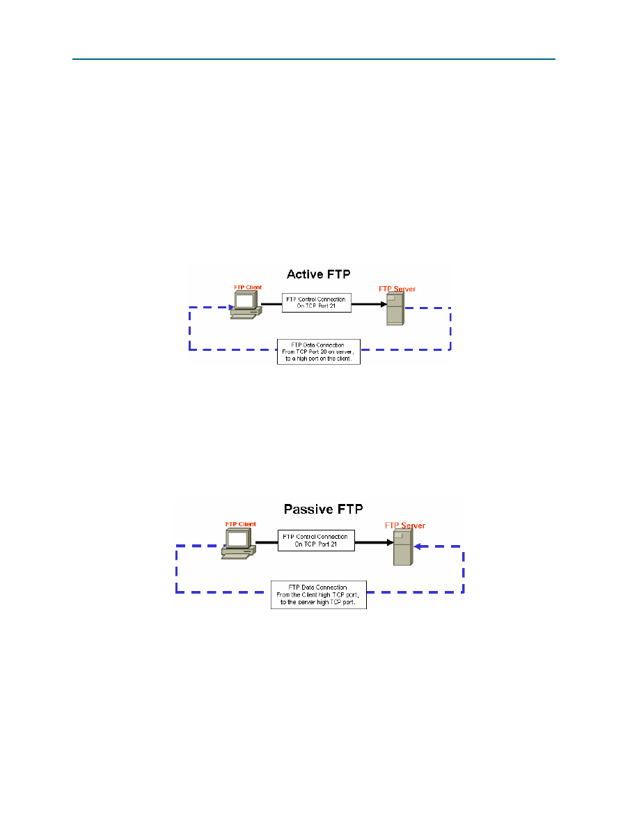
CCNA Exploration
Network Fundamentals: OSI Transport Layer
Lab 4.5.3: Application and Transport Layer Protocols Examination
All contents are Copyright © 1992–2007 Cisco Systems, Inc. All rights reserved. This document is Cisco Public Information. Page 10 of 11
What is the FTP-DATA port number used by the FTP server?
____________________________________________________________________________
4. Open the Wireshark capture FTP_Web_Browser_Client, and observe the FTP communication.
Although the clients are different, the commands are similar.
Step 5: FTP active and passive transfer modes
The implications between the two modes are very important from an information security perspective. The
transfer mode sets how the data port is configured.
In active transfer mode, a client initiates an FTP session with the server on well-known TCP port 21. For
data transfer, the server initiates a connection from well-known TCP port 20 to a client’s high port, a port
number above 1023. See Figure 9.
Figure 9.
Unless the FTP client firewall is configured to permit connections from the outside, data transfer may fail.
To establish connectivity for data transfer, the FTP client must permit either FTP-related connections
(implying stateful packet filtering), or disable blocking.
In passive transfer mode, a client initiates an FTP session with the server on well-known TCP port 21, the
same connection used in the active transfer mode. For data transfer, however, there are two significant
changes. First, the client initiates the data connection to the server. Second, high ports are used on both
ends of the connection. See Figure 10.
Figure 10.
Unless the FTP server is configured to permit a connection to a random high port, data transfer will fail.
Not all FTP client applications support changes to the transfer mode.
Task 4: Reflection
Both HTTP and FTP protocols rely on TCP to communicate. TCP manages the connection between client
and server to ensure datagram delivery.
A client application may be either a web browser or command line utility, but each must send and receive
messages that can be correctly interpreted. The communication protocol is normally defined in an RFC.

CCNA Exploration
Network Fundamentals: OSI Transport Layer
Lab 4.5.3: Application and Transport Layer Protocols Examination
All contents are Copyright © 1992–2007 Cisco Systems, Inc. All rights reserved. This document is Cisco Public Information. Page 11 of 11
The FTP client must authenticate to the FTP server, even if the authentication is open to the world. User
Anonymous normally has restricted access to the FTP server and cannot upload files.
An HTTP session begins when a request is made to the HTTP server and ends when the response has
been acknowledged by the HTTP client. An FTP session, however, lasts until the client signals that it is
leaving with the quit command.
HTTP uses a single protocol to communicate with the HTTP server. The server listens on port 80 for
client connections. FTP, however, uses two protocols. The FTP server listens on TCP port 21, as the
command line. Depending on the transfer mode, the server or client may initiate the data connection.
Multiple Application layer protocols can be accessed through a simple web browser. While only HTTP
and FTP were examined, Telnet and Gopher may also be supported on the browser. The browser acts as
a client to the server, sending requests and processing replies.
Task 5: Challenge
Enabling Wireshark capture, use a web browser or command line Telnet client to connect to a Cisco
device such as S1-Central or R2-Central. Observe the Telnet protocol behavior. Issue a GET request and
observe the results.
How is the Application layer protocol Telnet similar to HTTP and FTP? How is TELNET different?
____________________________________________________________________________
____________________________________________________________________________
Task 6: Clean Up
If Wireshark was installed on the pod host computer for this lab, the instructor may want the application
removed. To remove Wireshark, click Start > Control Panel > Add or Remove Programs. Scroll to the
bottom of the list, right-click on Wireshark, and click Remove.
If downloaded files need to be removed from the host pod computer, delete all files retrieved from the
FTP server.
Unless directed otherwise by the instructor, turn off power to the host computers. Remove anything that
was brought into the lab, and leave the room ready for the next class.
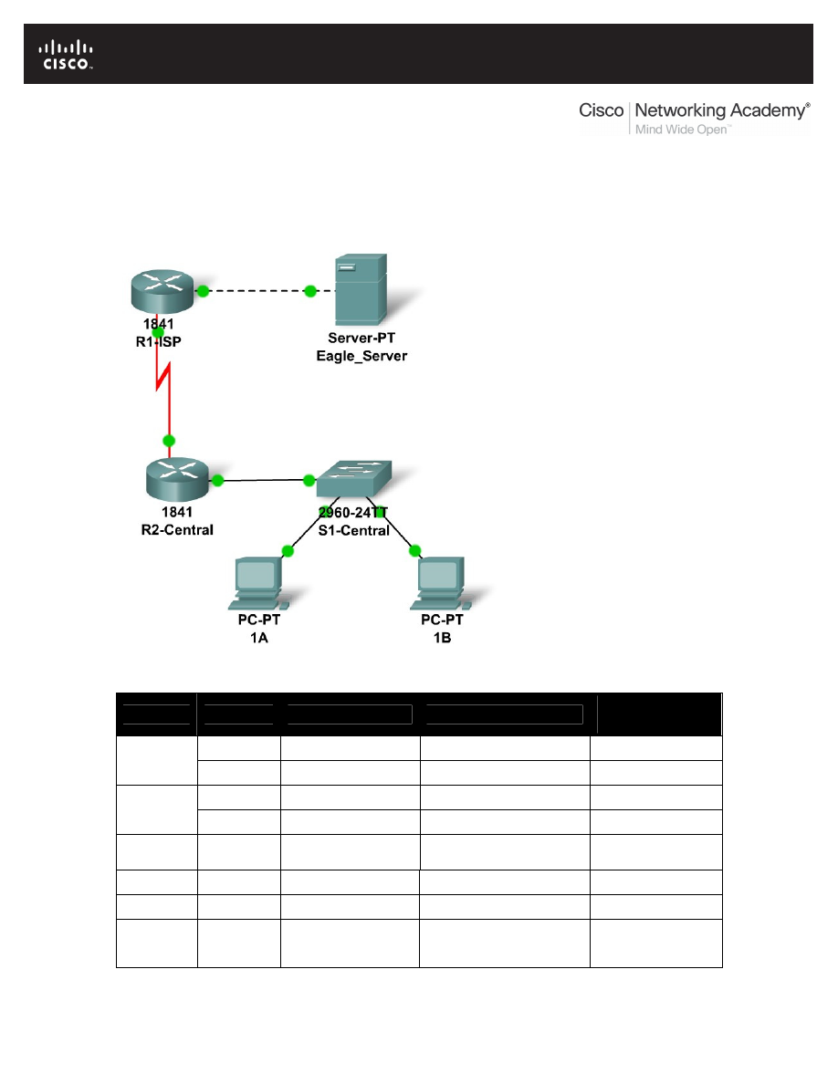
All contents are Copyright © 1992–2007 Cisco Systems, Inc. All rights reserved. This document is Cisco Public Information.
Page 1 of 3
4.6.1: Skills Integration Challenge-Analyzing the Application and
Transport Layers
Topology Diagram
Addressing Table
Device
Interface
IP Address
Subnet Mask
Default
Gateway
Fa0/0
192.168.254.253
255.255.255.0
N/A
R1-ISP
S0/0/0
10.10.10.6
255.255.255.252
N/A
Fa0/0
172.16.255.254
255.255.0.0
10.10.10.6
R2-
Central
S0/0/0
10.10.10.5
255.255.255.252
10.10.10.6
S1-
Central
VLAN 1
172.16.254.1
255.255.0.0
172.16.255.254
PC 1A
NIC
172.16.1.1
255.255.0.0
172.16.255.254
PC 1B
NIC
172.16.1.2
255.255.0.0
172.16.255.254
Eagle
Server
NIC
192.168.254.254
255.255.255.0
192.168.254.253

CCNA Exploration
Network Fundamentals:
OSI Transport Layer
4.6.1: Skills Integration Challenge-Analyzing the Application and Transport Layers
All contents are Copyright © 1992–2007 Cisco Systems, Inc. All rights reserved. This document is Cisco Public Information.
Page 2 of 3
Learning Objectives
•
Configure Hosts and Services
•
Connect and configure hosts and services on the model of the lab network
•
Explore How DNS, UDP, HTTP, and UDP Work Together
•
Use simulation mode to visualize the operation of DNS, UDP, HTTP, and TCP on the
model of the lab network.
Background
Throughout the course you will be using a standard lab setup created from actual PCs, servers,
routers, and switches to learn networking concepts. At the end of each chapter, you will build
increasingly larger parts of this topology in Packet Tracer, and analyze increasingly more
complex protocol interactions.
Task 1: Repair and Test the Topology.
The server has been replaced. It must be powered on. Then configure it with the following
settings: IP Address 192.168.254.254, Subnet Mask 255.255.255.0, Default Gateway
192.168.254.253, DNS enabled, with the association of eagle-server.example.com with the
server's IP address, HTTP enabled. Connect the Eagle Server to the Fa0/0 port on the R1-ISP
router using a crossover cable.
PC 1A has lost its IP address information. Configure it with the following settings: IP Address
172.16.1.1, Subnet Mask 255.255.0.0, Default Gateway 172.16.255.254, and DNS Server
192.168.254.254. Connect PC 1A to the Fa0/1 port of the S1-Central switch using a straight-
through cable.
Verify your work using feedback from the Check Results button and the Assessment Items tab.
Test connectivity, in realtime, by using ADD SIMPLE PDU to test connectivity between PC 1A
and the Eagle Server.
Note that when you add a simple PDU, it appears in the PDU List Window as part of "Scenario 0".
The first time you issue this one-shot ping message, it will show as Failed--this is because of the
ARP process which will be explained later. Double clicking the "Fire" button in the PDU List
Window, send this single test ping a second time. This time it will be successful. In Packet Tracer,
the term "scenario" means a specific configuration of one or more test packets. You can create
different test packet scenarios by using the New button--for example Scenario 0 might have one
test packet from PC 1A to Eagle Server; Scenario 1 might have test packets between PC 1B and
the routers; and so on. You can remove all test packets in a particular scenario by using the
Delete button. For example, if you use the Delete button for Scenario 0 the test packet you just
created between PC 1A and Eagle Server will be removed--please do this prior to the next task.
Task 2: Explore How DNS, UDP, HTTP, and TCP Work Together
Switch from Realtime to Simulation Mode. Make sure Event Filter is set to display DNS, UDP,
HTTP, TCP, and ICMP. Open a web browser from the desktop of 1A. Type in the URL eagle-
server.example.com, press Enter, and then use the Capture / Forward button in the Event List
to capture the interaction of DNS, UDP, HTTP and TCP.

CCNA Exploration
Network Fundamentals:
OSI Transport Layer
4.6.1: Skills Integration Challenge-Analyzing the Application and Transport Layers
All contents are Copyright © 1992–2007 Cisco Systems, Inc. All rights reserved. This document is Cisco Public Information.
Page 3 of 3
You can examine the packet in two ways: by clicking on the packet envelope as it is displayed in
the animation, or by clicking on the Info column for that packet instance as it is listed in the Event
List. Play this animation and examine the Packet contents (PDU Information Window, Inbound
PDU Details, Outbound PDU Details) for each event in the event list, especially when the
packets are at PC 1A or at the Eagle Server. If you receive a "Buffer Full" message, click the
View Previous Events button. While the processing of the packets at the switch and the routers
may not make sense to you yet, you should be able to see how DNS, UDP, HTTP, and TCP work
together by studying tracing the packets and using the PDU Information window to look "inside"
them.
Reflection
Can you make a diagram of the sequence of protocol events involved in requesting a web page
using a URL? Where might things go wrong? Compare and contrast DNS and HTTP, and UDP
and TCP.
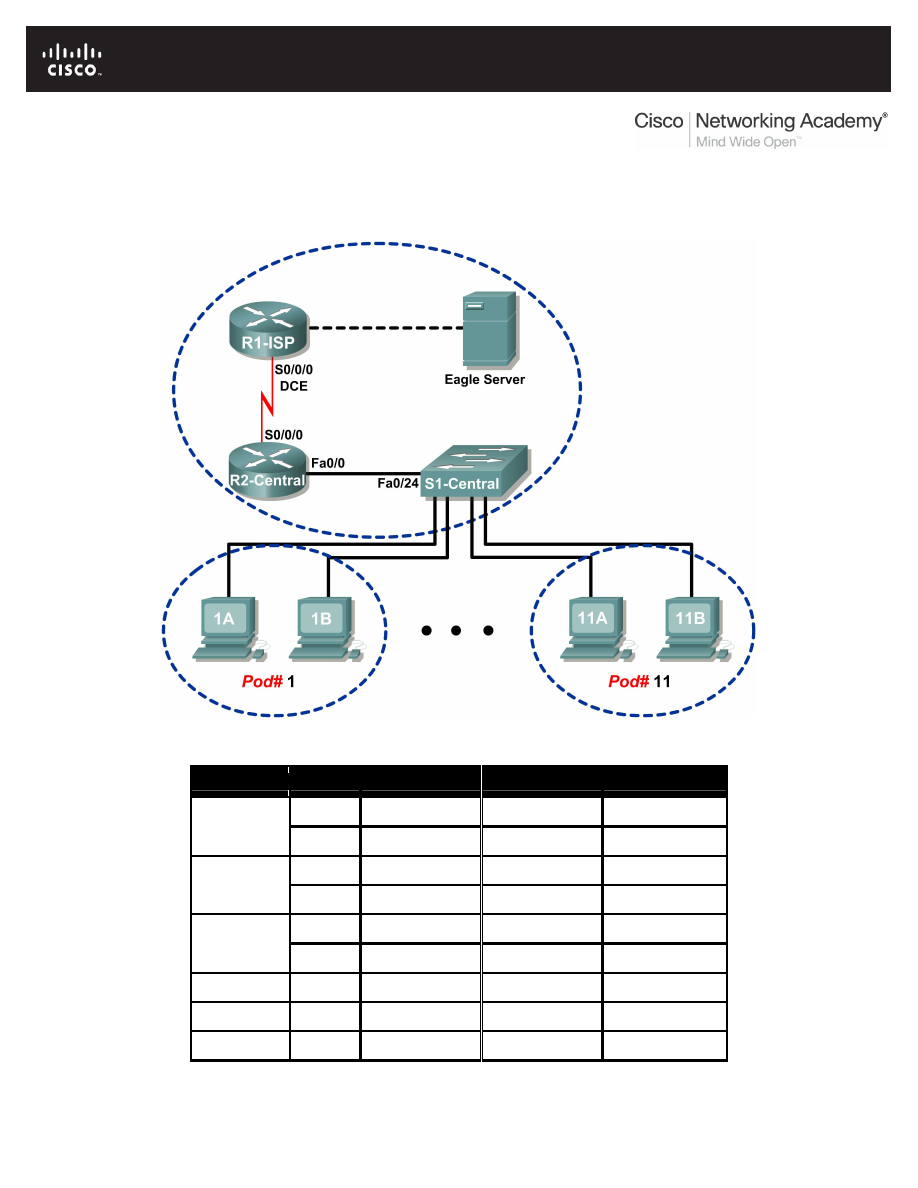
All contents are Copyright © 1992–2007 Cisco Systems, Inc. All rights reserved. This document is Cisco Public Information.
Page 1 of 8
Lab 5.5.1: Examining a Device’s Gateway
Topology Diagram
Addressing Table
Device
Interface IP Address
Subnet Mask
Default Gateway
S0/0/0
10.10.10.6
255.255.255.252 N/A
R1-ISP
Fa0/0
192.168.254.253 255.255.255.0
N/A
S0/0/0
10.10.10.5
255.255.255.252 10.10.10.6
R2-Central
Fa0/0
172.16.255.254 255.255.0.0
N/A
N/A
192.168.254.254 255.255.255.0
192.168.254.253
Eagle Server
N/A
172.31.24.254
255.255.255.0
N/A
hostPod#A
N/A
172.16.Pod#.1
255.255.0.0
172.16.255.254
hostPod#B
N/A
172.16.Pod#.2
255.255.0.0
172.16.255.254
S1-Central
N/A
172.16.254.1
255.255.0.0
172.16.255.254
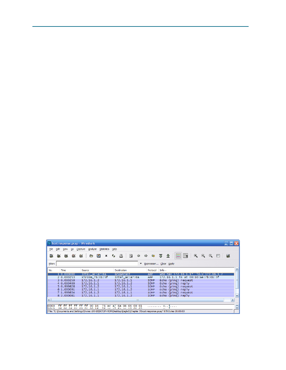
CCNA Exploration
Network Fundamentals: OSI Network Layer
Lab 5.5.1: Examining a Device’s Gateway
All contents are Copyright © 1992–2007 Cisco Systems, Inc. All rights reserved. This document is Cisco Public Information.
Page 2 of 8
Learning Objectives
Upon completion of this lab, you will be able to:
•
Understand and explain the purpose of a gateway address.
•
Understand how network information is configured on a Windows computer.
•
Troubleshoot a hidden gateway address problem.
Background
An IP address is composed of a network portion and a host portion. A computer that communicates with
another device must first know how to reach the device. For devices on the same local area network
(LAN), the host portion of the IP address is used as the identifier. The network portion of the destination
device is the same as the network portion of the host device.
However, devices on different networks have different source and destination network numbers. The
network portion of the IP address is used to identify when a packet must be sent to a gateway address,
which is assigned to a network device that forwards packets between distant networks.
A router is assigned the gateway address for all the devices on the LAN. One purpose of a router is to
serve as an entry point for packets coming into the network and exit point for packets leaving the network.
Gateway addresses are very important to users. Cisco estimates that 80 percent of network traffic will be
destined to devices on other networks, and only 20 percent of network traffic will go to local devices. This
is called the 80/20 rule. Therefore, if a gateway cannot be reached by the LAN devices, users will not be
able to perform their job.
Scenario
Pod host computers must communicate with Eagle Server, but Eagle Server is located on a different
network. If the pod host computer gateway address is not configured properly, connectivity with Eagle
Server will fail.
Using several common utilities, network configuration on a pod host computer will be verified.
Task 1: Understand and Explain the Purpose of a Gateway Address.
Figure 1. Communication Between LAN Devices
For local area network (LAN) traffic, the gateway address is the address of the Ethernet device. Figure 1
shows two devices on the same network communicating with the
ping command. Any device that has the
same network address—in this example, 172.16.0.0—is on the same LAN.

CCNA Exploration
Network Fundamentals: OSI Network Layer
Lab 5.5.1: Examining a Device’s Gateway
All contents are Copyright © 1992–2007 Cisco Systems, Inc. All rights reserved. This document is Cisco Public Information.
Page 3 of 8
Referring to Figure 1, what is the MAC address of the network device on IP address 172.16.1.1?
____________________________________________________________________________
There are several Windows commands that will display a network gateway address. One popular
command is netstat –r. In the following transcript, the netstat –r command is used to view the
gateway addresses for this computer. The top highlight shows what gateway address is used to forward
all network packets destined outside of the LAN. The ”quad-zero” Network Destination and Netmask
values, 0.0.0.0 and 0.0.0.0, refer to any network not specifically known. For any non-local network,
this computer will use 172.16.255.254 as the default gateway. The second yellow highlight displays
the information in human-readable form. More specific networks are reached through other gateway
addresses. A local interface, called the loopback interface, is automatically assigned to the 127.0.0.0
network. This interface is used to identify the local host to local network services. Refer to the gray
highlighted entry. Finally, any device on network 172.16.0.0 is accessed through gateway
172.16.1.2
, the IP address for this Ethernet interface. This entry is highlighted in green.
C:\>
netstat –r
Route Table
=======================================================================
Interface List
0x1 ......................... MS TCP Loopback interface
0x20005 ...00 16 76 ac a7 6a Intel(R) 82562V 10/100 Network Connection
=======================================================================
=======================================================================
Active Routes:
Network Destination Netmask Gateway Interface Metric
0.0.0.0 0.0.0.0 172.16.255.254 172.16.1.2 1
127.0.0.0 255.0.0.0 127.0.0.1 127.0.0.1 1
172.16.0.0 255.255.0.0 172.16.1.2 172.16.1.2 20
172.16.1.2 255.255.255.255 127.0.0.1 127.0.0.1 20
172.16.255.255 255.255.255.255 172.16.1.2 172.16.1.2 20
255.255.255.255 255.255.255.255 172.16.1.2 172.16.1.2 1
Default Gateway: 172.16.255.254
=======================================================================
Persistent Routes:
None
C:\>
Step 1: Open a terminal window on a pod host computer.
What is the default gateway address?
____________________________________________________________________________
Step 2: Use the ping command to verify connectivity with IP address 127.0.0.1.
Was the ping successful? __________
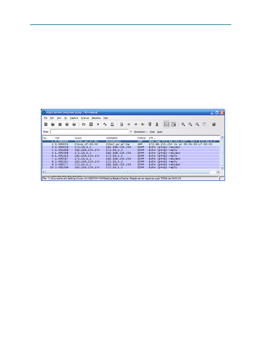
CCNA Exploration
Network Fundamentals: OSI Network Layer
Lab 5.5.1: Examining a Device’s Gateway
All contents are Copyright © 1992–2007 Cisco Systems, Inc. All rights reserved. This document is Cisco Public Information.
Page 4 of 8
Step 3: Use the ping command to ping different IP addresses on the 127.0.0.0 network,
127.10.1.1,
and 127.255.255.255.
Were responses successful? If not, why?
____________________________________________________________________________
____________________________________________________________________________
A default gateway address permits a network device to communicate with other devices on different
networks. In essence, it is the door to other networks. All traffic destined to different networks must go
through the network device that has the default gateway address.
Figure 2. Communication Between Devices on Different Networks
As shown in Figure 2, communication between devices on different networks is different than on a LAN.
Pod host computer #2, IP address 172.16.1.2, initiates a ping to IP address 192.168.254.254.
Because network 172.16.0.0 is different from 192.168.254.0, the pod host computer requests the
MAC address of the default gateway device. This gateway device, a router, responds with its MAC
address. The computer composes the Layer 2 header with the destination MAC address of the router and
places frames on the wire to the gateway device.
Referring to Figure 2, what is the MAC address of the gateway device?
____________________________________________________________________________
Referring to Figure 2, what is the MAC address of the network device with IP address 192.168.254.254?
____________________________________________________________________________
Task 2: Understand how Network Information is Configured on a Windows Computer.
Many times connectivity issues are attributed to wrong network settings. In troubleshooting connectivity
issues, several tools are available to quickly determine the network configuration for any Windows
computer.
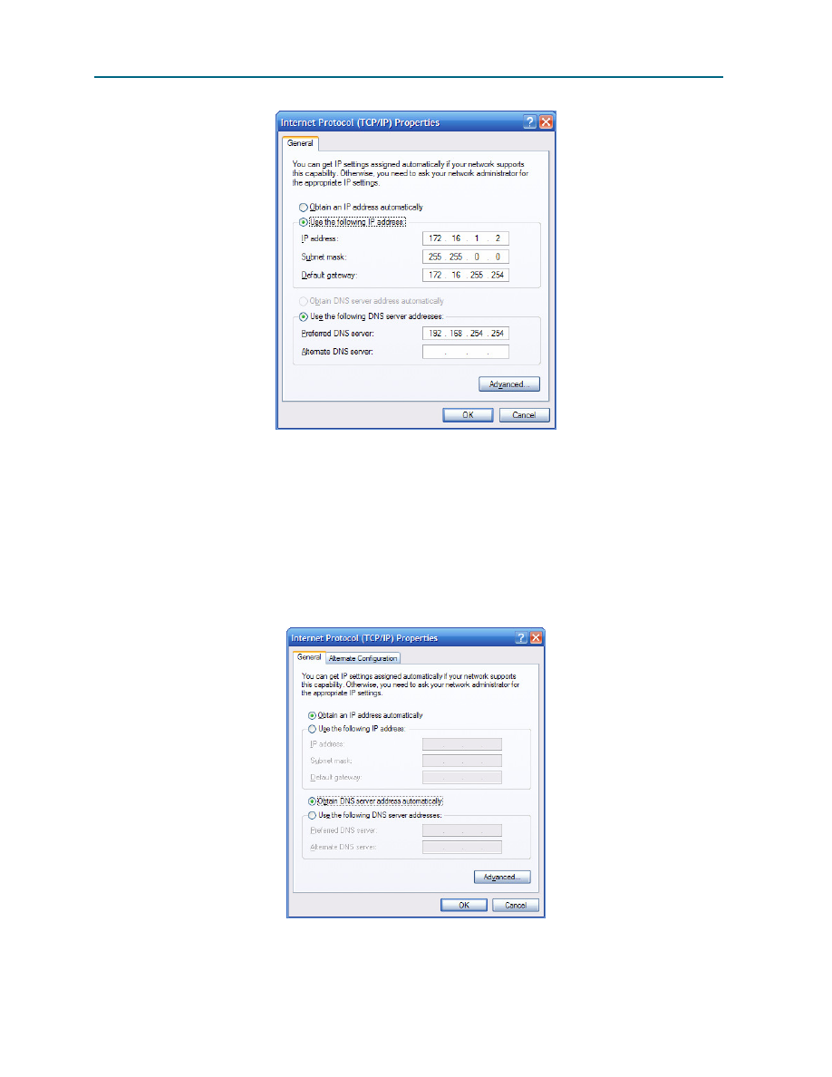
CCNA Exploration
Network Fundamentals: OSI Network Layer
Lab 5.5.1: Examining a Device’s Gateway
All contents are Copyright © 1992–2007 Cisco Systems, Inc. All rights reserved. This document is Cisco Public Information.
Page 5 of 8
Figure 3. Network Interface with Static IP Address
Step 1: Examine network properties settings.
One method that may be useful in determining the network interface IP properties is to examine the pod
host computer’s Network Properties settings. To access this window:
1. Click Start > Control Panel > Network Connections.
2. Right-click Local Area Connection, and choose Properties.
3. On the General tab, scroll down the list of items in the pane, select Internet Protocol (TCP/IP),
and click the Properties button. A window similar to the one in Figure 3 will be displayed.
Figure 4. Network Interface with Dynamic IP Address
However, a dynamic IP address may be configured, as shown in Figure 4. In this case, the Network
Properties settings window is not very useful for determining IP address information.
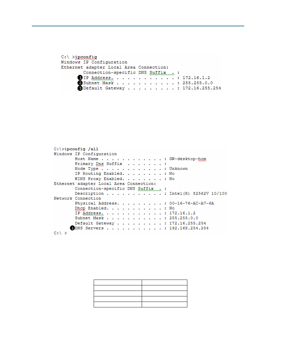
CCNA Exploration
Network Fundamentals: OSI Network Layer
Lab 5.5.1: Examining a Device’s Gateway
All contents are Copyright © 1992–2007 Cisco Systems, Inc. All rights reserved. This document is Cisco Public Information.
Page 6 of 8
A more consistently reliable method for determining network settings on a Windows computer is to use
the ipconfig command:
IP address for this pod host computer
Subnet mask
Default gateway address
There are several options available with the ipconfig command, accessible with the command
ipconfig /?
. To show the most information about the network connections, use the command
ipconfig /all
.
Domain name server IP address
Step 2: Using the command ipconfig /all, fill in the following table with information from your
pod host computer:
Description
Address
IP Address
Subnet Mask
Default Gateway
DNS Server
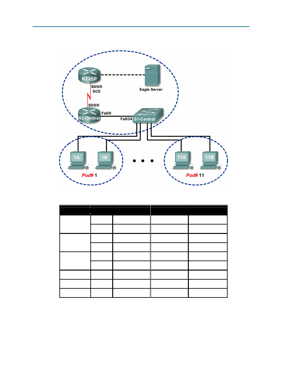
CCNA Exploration
Network Fundamentals: OSI Network Layer
Lab 5.5.1: Examining a Device’s Gateway
All contents are Copyright © 1992–2007 Cisco Systems, Inc. All rights reserved. This document is Cisco Public Information.
Page 7 of 8
Task 3: Troubleshoot a Hidden Gateway Address Problem.
Figure 5. Topology Diagram
Device
Interface IP Address
Subnet Mask
Default Gateway
S0/0/0
10.10.10.4
255.255.255.252 N/A
R1-ISP
Fa0/0
192.168.254.253 255.255.255.0
N/A
S0/0/0
10.10.10.3
255.255.255.252 10.10.10.4
R2-Central
Fa0/0
172.16.255.254 255.255.0.0
N/A
N/A
192.168.254.254 255.255.255.0
192.168.254.253
Eagle Server
N/A
172.31.24.254
255.255.255.0
N/A
hostPod#A
N/A
172.16.Pod#.1
255.255.0.0
172.16.255.254
hostPod#B
N/A
172.16.Pod#.2
255.255.0.0
172.16.255.254
S1-Central
N/A
172.16.254.1
255.255.0.0
172.16.255.254
Table 1. Logical Address Assignments
When troubleshooting network issues, a thorough understanding of the network can often assist in
identifying the real problem. Refer to the network topology in Figure 5 and the logical IP address
assignments in Table 1.

CCNA Exploration
Network Fundamentals: OSI Network Layer
Lab 5.5.1: Examining a Device’s Gateway
All contents are Copyright © 1992–2007 Cisco Systems, Inc. All rights reserved. This document is Cisco Public Information.
Page 8 of 8
As the 3rd shift help desk Cisco engineer, you are asked for assistance from the help desk technician.
The technician received a trouble ticket from a user on computer host-1A, complaining that computer
host-11B, host-11B.example.com, does not respond to pings. The technician verified the cables and
network settings on both computers, but nothing unusual was found. You check with the corporate
network engineer, who reports that R2-Central has been temporarily brought down for a hardware
upgrade.
Nodding your head in understanding, you ask the technician to ping the IP address for host-11B,
172.16.11.2
from host-1A. The pings are successful. Then, you ask the technician to ping the gateway
IP address, 172.16.254.254, and the pings fail.
What is wrong?
____________________________________________________________________________
____________________________________________________________________________
You instruct the help desk technician to tell the user to use the IP address for host-11B temporarily, and
the user is able to establish connectivity with the computer. Within the hour the gateway router is back on
line, and normal network operation resumes.
Task 4: Reflection
A gateway address is critical to network connectivity, and in some instances LAN devices require a
default gateway to communicate with other devices on the LAN.
Using Windows command line utilities such as netstat –r and ipconfig /all will report gateway
settings on host computers.
Task 5: Challenge
Use Wireshark to capture a ping between two pod host computers. It may be necessary to restart the
host computer to flush the DNS cache. First, use the hostname of the destination pod computer for DNS
to reply with the destination IP address. Observe the communication sequence between network devices,
especially the gateway. Next, capture a ping between network devices using only IP addresses. The
gateway address should not be needed.
Task 6: Clean Up
Unless directed otherwise by the instructor, turn off power to the host computers. Remove anything that
was brought into the lab, and leave the room ready for the next class.
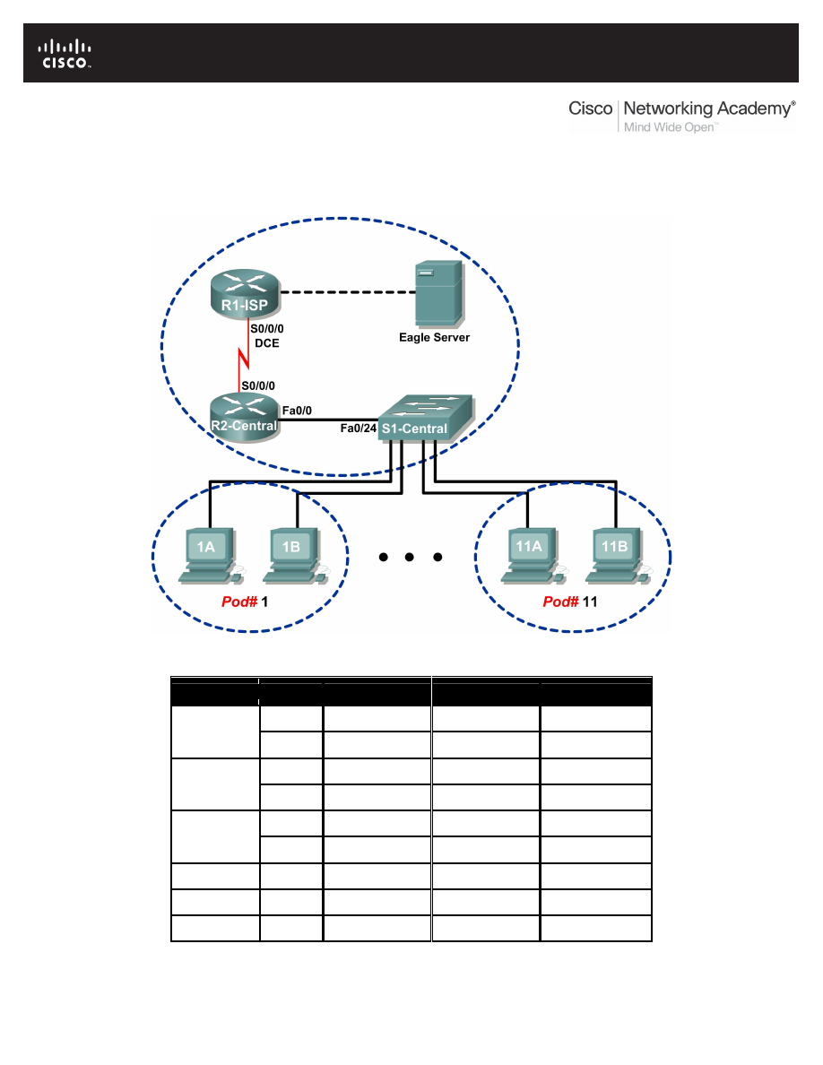
All contents are Copyright © 1992–2007 Cisco Systems, Inc. All rights reserved. This document is Cisco Public Information.
Page 1 of 7
Lab 5.5.2: Examining a Route
Topology Diagram
Addressing Table
Device
Interface IP Address
Subnet Mask
Default Gateway
S0/0/0
10.10.10.6
255.255.255.252 N/A
R1-ISP
Fa0/0
192.168.254.253 255.255.255.0
N/A
S0/0/0
10.10.10.5
255.255.255.252 10.10.10.6
R2-Central
Fa0/0
172.16.255.254 255.255.0.0
N/A
N/A
192.168.254.254 255.255.255.0
192.168.254.253
Eagle Server
N/A
172.31.24.254
255.255.255.0
N/A
hostPod#A
N/A
172.16.Pod#.1
255.255.0.0
172.16.255.254
hostPod#B
N/A
172.16.Pod#.2
255.255.0.0
172.16.255.254
S1-Central
N/A
172.16.254.1
255.255.0.0
172.16.255.254

CCNA Exploration
Network Fundamentals: OSI Network Layer
Lab 5.5.1: Examining a Route
All contents are Copyright © 1992–2007 Cisco Systems, Inc. All rights reserved. This document is Cisco Public Information.
Page 2 of 7
Learning Objectives
Upon completion of this lab, you will be able to:
•
Use the route command to modify a Windows computer routing table.
•
Use a Windows Telnet client command telnet to connect to a Cisco router.
•
Examine router routes using basic Cisco IOS commands.
Background
For packets to travel across a network, a device must know the route to the destination network. This lab
will compare how routes are used in Windows computers and the Cisco router.
Some routes are added to routing tables automatically, based upon configuration information on the
network interface. The device considers a network directly connected when it has an IP address and
network mask configured, and the network route is automatically entered into the routing table. For
networks that are not directly connected, a default gateway IP address is configured that will send traffic
to a device that should know about the network.
Scenario
Using a pod host computer, examine the routing table with the route command and identify the different
routes and gateway IP address for the route. Delete the default gateway route, test the connection, and
then add the default gateway route back to the host table.
Use a pod host computer to telnet into R2-Central, and examine the routing table.
Task 1: Use the route Command to Modify a Windows Computer Routing Table.
C:\>
netstat –r
Route Table
=======================================================================
Interface List
0x1 ......................... MS TCP Loopback interface
0x20005 ...00 16 76 ac a7 6a Intel(R) 82562V 10/100 Network Connection
=======================================================================
=======================================================================
Active Routes:
Network Destination Netmask Gateway Interface Metric
0.0.0.0 0.0.0.0 172.16.255.254 172.16.1.2 1
127.0.0.0 255.0.0.0 127.0.0.1 127.0.0.1 1
172.16.0.0 255.255.0.0 172.16.1.2 172.16.1.2 20
172.16.1.2 255.255.255.255 127.0.0.1 127.0.0.1 20
172.16.255.255 255.255.255.255 172.16.1.2 172.16.1.2 20
255.255.255.255 255.255.255.255 172.16.1.2 172.16.1.2 1
Default Gateway: 172.16.255.254
=======================================================================
Persistent Routes:
None
C:\>
Figure 1. Output of the netstat Command
Shown in Figure 1, output from the netstat –r command is useful to determine route and gateway
information.

CCNA Exploration
Network Fundamentals: OSI Network Layer
Lab 5.5.1: Examining a Route
All contents are Copyright © 1992–2007 Cisco Systems, Inc. All rights reserved. This document is Cisco Public Information.
Page 3 of 7
Step 1: Examine the active routes on a Windows computer.
A useful command to modify the routing table is the route command. Unlike the netstat –r
command, the route command can be used to view, add, delete, or change routing table entries. To
view detailed information about the route command, use the option route /?.
An abbreviated option list for the route command is shown below:
route PRINT
Prints active routes
route ADD
Adds a route:
route ADD network MASK mask gateway
route DELETE
Deletes a route:
route DELETE network
route CHANGE
Modifies an existing route
To view active routes, issue the command route PRINT:
C:\ >
route PRINT
=======================================================================
Interface List
0x1 ........................... MS TCP Loopback interface
0x70003 ...00 16 76 ac a7 6a .Intel(R) 82562V 10/100 Network Connection
=======================================================================
=======================================================================
Active Routes:
Network Destination Netmask Gateway Interface Metric
0.0.0.0 0.0.0.0 172.16.255.254 172.16.1.2 1
127.0.0.0 255.0.0.0 127.0.0.1 127.0.0.1 1
172.16.0.0 255.255.0.0 172.16.1.2 172.16.1.2 20
172.16.1.2 255.255.255.255 127.0.0.1 127.0.0.1 20
172.16.255.255 255.255.255.255 172.16.1.2 172.16.1.2 20
255.255.255.255 255.255.255.255 172.16.1.2 172.16.1.2 1
Default Gateway: 172.16.255.254
=======================================================================
Persistent Routes:
None
C:\>
Verify network connectivity to Eagle Server:
C:\>
ping eagle-server.example.com
Pinging eagle-server.example.com [192.168.254.254] with 32 bytes
of data:
Reply from 192.168.254.254: bytes=32 time<1ms TTL=63
Reply from 192.168.254.254: bytes=32 time<1ms TTL=63
Reply from 192.168.254.254: bytes=32 time<1ms TTL=63
Reply from 192.168.254.254: bytes=32 time<1ms TTL=63
Ping statistics for 192.168.254.254:
Packets: Sent = 4, Received = 4, Lost = 0 (0% loss),
Approximate round trip times in milli-seconds:
Minimum = 0ms, Maximum = 0ms, Average = 0ms
C:\>
What is the gateway address to eagle-server.example.com?
____________________________________________________________________________

CCNA Exploration
Network Fundamentals: OSI Network Layer
Lab 5.5.1: Examining a Route
All contents are Copyright © 1992–2007 Cisco Systems, Inc. All rights reserved. This document is Cisco Public Information.
Page 4 of 7
Step 2: Delete a route from the Windows computer routing table.
How important is the default gateway route? Delete the gateway route, and try to ping Eagle Server. The
syntax to remove the default gateway route is:
route DELETE network
C:/>
route DELETE 0.0.0.0
Examine the active routing table and verify that the default gateway route has been removed:
What is the default gateway IP address?
____________________________________________________________________________
Try to ping Eagle Server. What are the results?
____________________________________________________________________________
If the default gateway IP address is removed, how can the DNS server be reached to resolve eagle-
server.example.com
?
Can other LAN devices be reached, such as 172.16.255.254?
____________________________________________________________________________
Step 3: Insert a route into the Windows computer routing table.
In the following configuration, use the IP address assigned to your host pod interface. The syntax to add a
route to the Windows computer routing table is:
route ADD network MASK mask gateway-IP address
C:/>
route ADD 0.0.0.0 MASK 0.0.0.0 172.16.255.
254
Examine the active routing table, and verify that the default gateway route has been restored:
Has the default gateway route been restored? __________:
Try to ping Eagle Server. What are the results?
____________________________________________________________________________
Task 2: Use a Windows Telnet Client Command telnet to Connect to a Cisco Router.
In this task, uou will telnet into the R2-Central router and use common IOS commands to examine the
router routing table. Cisco devices have a Telnet server and, if properly configured, will permit remote
logins. Access to the router is restricted, however, and requires a username and password. The
password for all usernames is cisco. The username depends on the pod. Username ccna1 is for users
on pod 1 computer, ccna2 is for students on pod 2 computers, and so on.
Step 1: Using the Windows Telnet client, log in to a Cisco router.
Open a terminal window by clicking Start > Run. Type cmd, and click OK. A terminal window and prompt
should be available. The Telnet utility has several options and can be viewed with the telnet /?
command. A username and password will be required to log in to the router. For all usernames, the
corresponding password is cisco.

CCNA Exploration
Network Fundamentals: OSI Network Layer
Lab 5.5.1: Examining a Route
All contents are Copyright © 1992–2007 Cisco Systems, Inc. All rights reserved. This document is Cisco Public Information.
Page 5 of 7
Pod Number
Username
1
ccna1
2
ccna2
3
ccna3
4
ccna4
5
ccna5
6
ccna6
7
ccna7
8
ccna8
9
Ccna9
10
ccna10
11
ccna11
To start a Telnet session with router R2-central, type the command:
C:/> telnet 172.16.255.254 <ENTER>
A login window will prompt for a username, as shown below. Enter the applicable username, and press
<ENTER>
. Enter the password, cisco, and press <ENTER>. The router prompt should be visible after a
successful login.
*****************************************************************
This is Eagle 1 lab router R2-Central.
Authorized access only.
*****************************************************************
User Access Verification
Username:
ccna1
Password:
cisco
(hidden)
R2-Central#
At the prompt, R2-Central#, a successful Telnet login has been created. Only limited permissions for
ccnax
usernames are available; therefore, it is not possible to modify router settings or view the
configuration. The purpose of this task was to establish a Telnet session, which has been accomplished.
In the next task, the router routing table will be examined.
Task 3: Examine Router Routes using Basic Cisco IOS Commands.
As with any network device, gateway addresses instruct the device about how to reach other networks
when no other information is available. Similar to the host computer default gateway IP address, a router
may also employ a default gateway. Also similar to a host computer, a router is knowledgeable about
directly connected networks.
This task will not examine Cisco IOS commands in detail but will use a common IOS command to view
the routing table. The syntax to view the routing table is:
show ip route <ENTER>
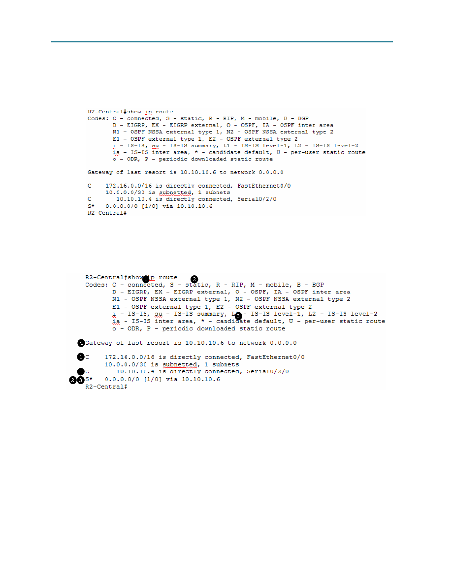
CCNA Exploration
Network Fundamentals: OSI Network Layer
Lab 5.5.1: Examining a Route
All contents are Copyright © 1992–2007 Cisco Systems, Inc. All rights reserved. This document is Cisco Public Information.
Page 6 of 7
Step 1: Enter the command to display the router routing table.
The route information displayed is much more detailed than the route information on a host computer.
This is to be expected, because the job of a router is to route traffic between networks. The information
required of this task, however, is not difficult to glean. Figure 2 shows the routing table for R2-Central.
Figure 2. Output of the Cisco IOS show ip route Command
The Codes section shown in Figure 3 provides an explanation for the symbols to the left of each route
entry.
Figure 3. Explanation of Codes
C
denotes directly connected networks and the interface that supports the connection.
S
denotes a static route, which is manually entered by the Cisco network engineer.
Because the route is ”quad-zero,” it is a candidate default route.
If there is no other route in the routing table, use this gateway of last resort IP
address to forward packets.
How is IP mask information displayed in a router routing table?
____________________________________________________________________________
____________________________________________________________________________

CCNA Exploration
Network Fundamentals: OSI Network Layer
Lab 5.5.1: Examining a Route
All contents are Copyright © 1992–2007 Cisco Systems, Inc. All rights reserved. This document is Cisco Public Information.
Page 7 of 7
What would the router do with packets destined to 192.168.254.254?
____________________________________________________________________________
____________________________________________________________________________
When finished examining the routing table, exit the router with the command exit <ENTER>. The
telnet client will also close the connection with the telnet escape sequence <CTRL> ] and quit. Close
the terminal window.
Task 4: Reflection
Two new Windows commands were used in this lab. The route command was used to view, delete, and
add route information on the pod host computer.
The Windows Telnet client, telnet, was used to connect to a lab router, R2-Central. This technique will
be used in other labs to connect to Cisco network devices.
The router routing table was examined with the Cisco IOS command show ip route. Routes for
directly connected networks, statically assigned routes, and gateway of last resort information are
displayed.
Task 5: Challenge
Other Cisco IOS commands can be used to view IP address information on a router. Similar to the
Windows ipconfig command, the Cisco IOS command show ip interface brief will display IP
address assignments.
R2-Central#show ip interface brief
Interface IP-Address OK? Method Status Protocol
FastEthernet0/0 172.16.255.254 YES manual up up
FastEthernet0/1 unassigned YES unset administratively down down
Serial0/2/0 10.10.10.5 YES manual up up
Serial0/2/1 unassigned YES unset administratively down down
R2-Central#
Using Windows commands and the Cisco IOS commands in this lab, compare network information
output. What was missing? What critical network information was similar?
____________________________________________________________________________
____________________________________________________________________________
Task 6: Clean Up
Unless directed otherwise by the instructor, turn off power to the host computers. Remove anything that
was brought into the lab, and leave the room ready for the next class.
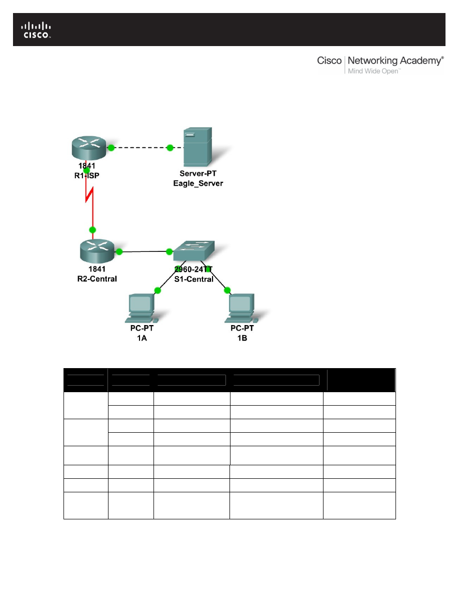
All contents are Copyright © 1992–2007 Cisco Systems, Inc. All rights reserved. This document is Cisco Public Information.
Page 1 of 3
5.6.1: Skills Integration Challenge-Routing IP Packets
Topology Diagram
Addressing Table
Device
Interface
IP Address
Subnet Mask
Default
Gateway
Fa0/0
192.168.254.253
255.255.255.0
N/A
R1-ISP
S0/0/0
10.10.10.6
255.255.255.252
N/A
Fa0/0
172.16.255.254
255.255.0.0
10.10.10.6
R2-
Central
S0/0/0
10.10.10.5
255.255.255.252
10.10.10.6
S1-
Central
VLAN 1
172.16.254.1
255.255.0.0
172.16.255.254
PC 1A
NIC
172.16.1.1
255.255.0.0
172.16.255.254
PC 1B
NIC
172.16.1.2
255.255.0.0
172.16.255.254
Eagle
Server
NIC
192.168.254.254
255.255.255.0
192.168.254.253

CCNA Exploration
Network Fundamentals:
OSI Network Layer
5.6.1: Skills Integration Challenge-Routing IP Packets
All contents are Copyright © 1992–2007 Cisco Systems, Inc. All rights reserved. This document is Cisco Public Information.
Page 2 of 3
Learning Objectives
•
Configure a router interface using a GUI.
•
Explore a routing table.
•
Configure a static route using a GUI.
•
Explore the routing of IP packets.
Background
Throughout the course you will be using a standard lab setup created from actual PCs, servers,
routers, and switches to learn networking concepts. At the end of each chapter, you will build
increasingly larger parts of this topology in Packet Tracer, and analyze increasingly more
complex protocol interactions. You have already studied a varieity of application protocols, such
as DNS, HTTP, TFTP, DHCP, and Telnet, and two transport layer protocols, TCP and UDP. You
may have noticed that regardless of what application and transport protocols were involved, in
Inbound and Outbound PDU Details view they were always encapsulated in IP Packets. In this
activity we will examine how the Internet Protocol, the dominant network layer protocol of the
Internet, works in the context of a simple example of IP routing.
Task 1: Configure a Router Interface.
There are problems on the local area network: PC 1A cannot reach the Eagle Server (verify this
in Realtime mode). It appears there is a problem with the router. Mouse over the R2-Central
router, and note the condition of the Fa0/0 interface (to which switch is connected. This interface
must have an IP address, subnet mask, and be turned on in order to act as the default gateway
for the LAN. Click on router R2-Central, and go to the Config tab. At the end of the course, you
will learn how to use the Cisco Internetwork Operating System (IOS) command line interface
(CLI) to perform this task. For now, the Config tab is easier and will allow you to focus on the
basic idea of IP routing. In the list shown, find INTERFACE, FastEthernet0/0. Add the IP address
172.16.255.254 with subnet mask of 255.255.0.0, and turn the port on. Close the router window.
Verify that the router interface (port) is now working by using the mouse over. Try reaching Eagle
Server. The request still fails. What are some possible reasons why?
Task 2: Examining Routes.
Use the Inspect Tool (magnifying glass) to examine the routing table of R2-Central. You will see
the router's directly connected networks, but there is no way to reach the Eagle Server network.
Task 3: Configure a Route Using a GUI.
Click on router R2-Central and go to the Config tab. In the list shown find ROUTING, Static.
Configure what is known as a default static route, using the address 0.0.0.0, mask 0.0.0.0, and
the next hop of 10.10.10.6 (the S0/0/0 interface on the R1-ISP router) and click the Add button.
This route is configured so that wherever packets from the 172.16.0.0 /16 LAN are destined, they
will go to the R1-ISP router. Under GLOBAL, Settings, click on the Save button to save the
interface and route configuration you have just done to NVRAM in case the router is power
cycled. Use the Inspect Tool (magnifying glass) to examine the routing table of R2-Central
again. You should now see the route you configured in the routing table.
Verify your work using feedback from the Check Results button and the Assessment Items tab.
Test connectivity, in Realtime, by using ADD SIMPLE PDU to test connectivity between PC 1A
and the Eagle Server. The PDU, a one-shot ping, will appear in the User Created PDU List for
future use as well.

CCNA Exploration
Network Fundamentals:
OSI Network Layer
5.6.1: Skills Integration Challenge-Routing IP Packets
All contents are Copyright © 1992–2007 Cisco Systems, Inc. All rights reserved. This document is Cisco Public Information.
Page 3 of 3
Task 4: Examine the Routing of the IP Packet.
Switch to Simulation mode. Using the PDU you created in Task 3, double click on Fire to send it
again. Trace the packet's journey from PC 1A to Eagle Server and back using the Capture /
Forward button and examining the packet's contents by either clicking on the envelope or
clicking on the colored square in the Info column of the Event List.
Reflection
What data can an IP Packet contain? What is meant by the phrase "the IP packet is routed"?
What is a route? Where might things go wrong?
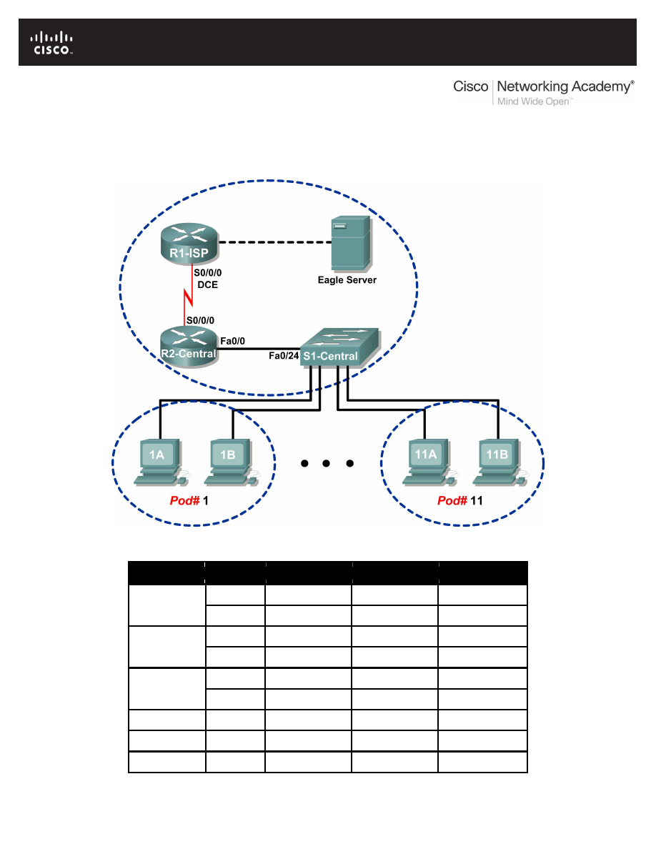
All contents are Copyright © 1992–2007 Cisco Systems, Inc. All rights reserved. This document is Cisco Public Information.
Page 1 of 8
Lab 6.7.1: Ping and Traceroute
Topology Diagram
Addressing Table
Device
Interface
IP Address
Subnet Mask
Default Gateway
S0/0/0
10.10.10.6
255.255.255.252 N/A
R1-ISP
Fa0/0
192.168.254.253 255.255.255.0
N/A
S0/0/0
10.10.10.5
255.255.255.252 10.10.10.6
R2-Central
Fa0/0
172.16.255.254 255.255.0.0
N/A
N/A
192.168.254.254 255.255.255.0
192.168.254.253
Eagle Server
N/A
172.31.24.254
255.255.255.0
N/A
hostPod#A
N/A
172.16.Pod#.1
255.255.0.0
172.16.255.254
hostPod#B
N/A
172.16.Pod#.2
255.255.0.0
172.16.255.254
S1-Central
N/A
172.16.254.1
255.255.0.0
172.16.255.254

CCNA Exploration
Network Fundamentals: Addressing the Network - IPV4
Lab 6.7.1: Ping and Traceroute
All contents are Copyright © 1992–2007 Cisco Systems, Inc. All rights reserved. This document is Cisco Public Information.
Page 2 of 8
Learning Objectives
Upon completion of this lab, you will be able to:
•
Use the ping command to verify simple TCP/IP network connectivity.
•
Use the tracert/traceroute command to verify TCP/IP connectivity.
Background
Two tools that are indispensable when testing TCP/IP network connectivity are ping and tracert. The
ping
utility is available on Windows, Linux, and Cisco IOS, and tests network connectivity. The tracert
utility is available on Windows, and a similar utility, traceroute, is available on Linux and Cisco IOS. In
addition to testing for connectivity, tracert can be used to check for network latency.
For example, when a web browser fails to connect to a web server, the problem can be anywhere
between client and the server. A network engineer may use the ping command to test for local network
connectivity or connections where there are few devices. In a complex network, the tracert command
would be used. Where to begin connectivity tests has been the subject of much debate; it usually
depends on the experience of the network engineer and familiarity with the network.
The Internet Control Message Protocol (ICMP) is used by both ping and tracert to send messages
between devices. ICMP is a TCP/IP Network layer protocol, first defined in RFC 792, September, 1981.
ICMP message types were later expanded in RFC 1700.
Scenario
In this lab, the ping and tracert commands will be examined, and command options will be used to
modify the command behavior. To familiarize the students with the use of the commands, devices in the
Cisco lab will be tested.
Measured delay time will probably be less than those on a production network. This is because there is
little network traffic in the Eagle 1 lab.
Task 1: Use the ping Command to Verify Simple TCP/IP Network Connectivity.
The ping command is used to verify TCP/IP Network layer connectivity on the local host computer or
another device in the network. The command can be used with a destination IP address or qualified
name, such as eagle-server.example.com, to test domain name services (DNS) functionality. For this lab,
only IP addresses will be used.
The ping operation is straightforward. The source computer sends an ICMP echo request to the
destination. The destination responds with an echo reply. If there is a break between the source and
destination, a router may respond with an ICMP message that the host is unknown or the destination
network is unknown.
Step 1: Verify TCP/IP Network layer connectivity on the local host computer.
C:\>
ipconfig
Windows IP Configuration
Ethernet adapter Local Area Connection:
Connection-specific DNS Suffix . :
IP Address. . . . . . . . . . . . : 172.16.1.2
Subnet Mask . . . . . . . . . . . : 255.255.0.0
Default Gateway . . . . . . . . . : 172.16.255.254
C:\>
Figure 1. Local TCP/IP Network Information
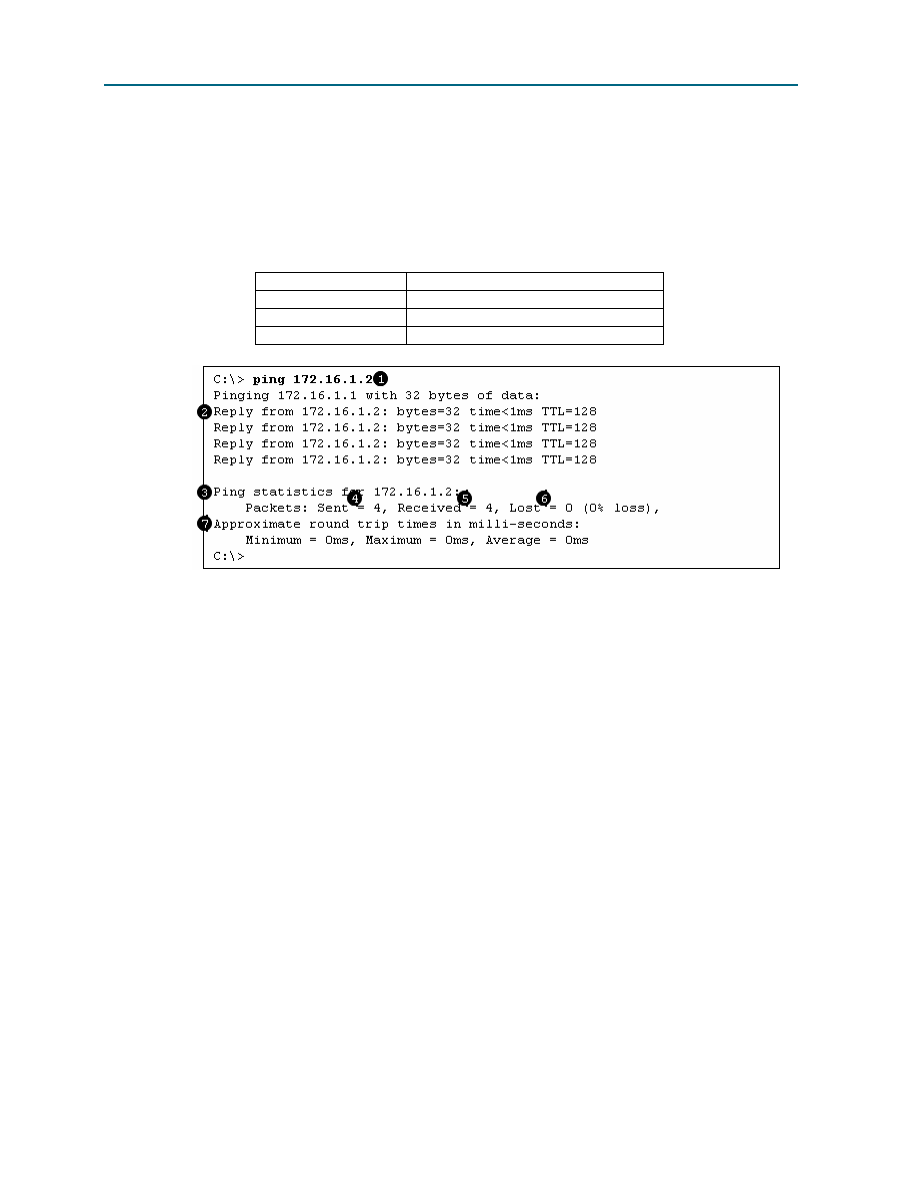
CCNA Exploration
Network Fundamentals: Addressing the Network - IPV4
Lab 6.7.1: Ping and Traceroute
All contents are Copyright © 1992–2007 Cisco Systems, Inc. All rights reserved. This document is Cisco Public Information.
Page 3 of 8
1. Open a Windows terminal and determine IP address of the pod host computer with the
ipconfig
command, as shown in Figure 1.
The output should look the same except for the IP address. Each pod host computer should have
the same network mask and default gateway address; only the IP address may differ. If the
information is missing or if the subnet mask and default gateway are different, reconfigure the
TCP/IP settings to match the settings for this pod host computer.
2. Record information about local TCP/IP network information:
TCP/IP Information
Value
IP Address
Subnet Mask
Default Gateway
Figure 2. Output of the ping Command on the Local TCP/IP Stack
3. Use the ping command to verify TCP/IP Network layer connectivity on the local host computer.
By default, four ping requests are sent to the destination and reply information is received. Output
should look similar to that shown in Figure 2.
Destination address, set to the IP address for the local computer.
Reply information:
bytes—size of the ICMP packet.
time—elapsed time between transmission and reply.
TTL—default TTL value of the DESTINATION device, minus the number of routers in the
path. The maximum TTL value is 255, and for newer Windows machines the default
value is 128.
Summary information about the replies:
Packets Sent—number of packets transmitted. By default, four packets are sent.
Packets Received—number of packets received.
Packets Lost —difference between number of packets sent and received.
Information about the delay in replies, measured in milliseconds. Lower round trip
times indicate faster links. A computer timer is set to 10 milliseconds. Values faster than
10 milliseconds will display 0.

CCNA Exploration
Network Fundamentals: Addressing the Network - IPV4
Lab 6.7.1: Ping and Traceroute
All contents are Copyright © 1992–2007 Cisco Systems, Inc. All rights reserved. This document is Cisco Public Information.
Page 4 of 8
4. Fill in the results of the ping command on your computer:
Field
Value
Size of packet
Number of packets sent
Number of replies
Number of lost packets
Minimum delay
Maximum delay
Average delay
Step 2: Verify TCP/IP Network layer connectivity on the LAN.
C:\>
ping 172.16.255.254
Pinging 172.16.255.254 with 32 bytes of data:
Reply from 172.16.255.254: bytes=32 time=1ms TTL=255
Reply from 172.16.255.254: bytes=32 time<1ms TTL=255
Reply from 172.16.255.254: bytes=32 time<1ms TTL=255
Reply from 172.16.255.254: bytes=32 time<1ms TTL=255
Ping statistics for 172.16.255.254:
Packets: Sent = 4, Received = 4, Lost = 0 (0% loss),
Approximate round trip times in milli-seconds:
Minimum = 0ms, Maximum = 1ms, Average = 0ms
C:\>
Figure 3. Output of the ping Command to the Default Gateway
1. Use the ping command to verify TCP/IP Network layer connectivity to the default gateway.
Results should be similar to those shown in Figure 3.
Cisco IOS default TTL value is set to 255. Because the router was not crossed, the TTL value
returned is 255.
2. Fill in the results of the ping command to the default Gateway:
Field
Value
Size of packet
Number of packets sent
Number of replies
Number of lost packets
Minimum delay
Maximum delay
Average delay
What would be the result of a loss of connectivity to the default gateway?
___________________________________________________________________________________

CCNA Exploration
Network Fundamentals: Addressing the Network - IPV4
Lab 6.7.1: Ping and Traceroute
All contents are Copyright © 1992–2007 Cisco Systems, Inc. All rights reserved. This document is Cisco Public Information.
Page 5 of 8
Step 3: Verify TCP/IP Network layer connectivity to a remote network.
C:\>
ping 192.168.254.254
Pinging 192.168.254.254 with 32 bytes of data:
Reply from 192.168.254.254: bytes=32 time<1ms TTL=62
Reply from 192.168.254.254: bytes=32 time<1ms TTL=62
Reply from 192.168.254.254: bytes=32 time<1ms TTL=62
Reply from 192.168.254.254: bytes=32 time<1ms TTL=62
Ping statistics for 192.168.254.254:
Packets: Sent = 4, Received = 4, Lost = 0 (0% loss),
Approximate round trip times in milli-seconds:
Minimum = 0ms, Maximum = 0ms, Average = 0ms
C:\>
Figure 4. Output of the ping Command to Eagle Server
1. Use the ping command to verify TCP/IP Network layer connectivity to a device on a remote
network. In this case, Eagle Server will be used. Results should be similar to those shown in
Figure 4.
Linux default TTL value is set to 64. Two routers were crossed to reach Eagle Server, therefore
the returned TTL value is 62.
2. Fill in the results of the ping command on your computer:
Field
Value
Size of packet
Number of packets sent
Number of replies
Number of lost packets
Minimum delay
Maximum delay
Average delay
C:\ >
ping 192.168.254.254
Pinging 192.168.254.254 with 32 bytes of data:
Request timed out.
Request timed out.
Request timed out.
Request timed out.
Ping statistics for 192.168.254.254:
Packets: Sent = 4, Received = 0, Lost = 4 (100% loss),
C:\>
Figure 5. Output of a ping Command with Lost Packets
The ping command is extremely useful when troubleshooting network connectivity. However, there are
limitations. In Figure 5, the output shows that a user cannot reach Eagle Server. Is the problem with
Eagle Server or a device in the path? The tracert command, examined next, can display network
latency and path information.

CCNA Exploration
Network Fundamentals: Addressing the Network - IPV4
Lab 6.7.1: Ping and Traceroute
All contents are Copyright © 1992–2007 Cisco Systems, Inc. All rights reserved. This document is Cisco Public Information.
Page 6 of 8
Task 2: Use the tracert Command to Verify TCP/IP Connectivity.
The tracert command is useful for learning about network latency and path information. Instead of
using the ping command to test connectivity of each device to the destination, one by one, the tracert
command can be used.
On Linux and Cisco IOS devices, the equivalent command is traceroute.
Step 1: Verify TCP/IP Network layer connectivity with the tracert command.
1. Open a Windows terminal and issue the following command:
C:\>
tracert 192.168.254.254
C:\>
tracert 192.168.254.254
Tracing route to 192.168.254.254 over a maximum of 30 hops
1 <1 ms <1 ms <1 ms 172.16.255.254
2 <1 ms <1 ms <1 ms 10.10.10.6
3 <1 ms <1 ms <1 ms 192.168.254.254
Trace complete.
C:\>
Figure 6. Output of the tracrt command to Eagle Server.
Output from the tracert command should be similar to that shown in Figure 6.
2. Record your result in the following table:
Field
Value
Maximum number of hops
First router IP address
Second router IP address
Destination reached?
Step 2: Observe tracert output to a host that lost network connectivity.
If there is a loss of connectivity to an end device such as Eagle Server, the tracert command can give
valuable clues as to the source of the problem. The ping command would show the failure but not any
other kind of information about the devices in the path. Referring to the Eagle 1 lab Topology Diagram,
both R2-Central and R1-ISP are used for connectivity between the pod host computers and Eagle Server.
C:\>
tracert -w 5 -h 4 192.168.254.254
Tracing route to 192.168.254.254 over a maximum of 4 hops
1 <1 ms <1 ms <1 ms 172.16.255.254
2 <1 ms <1 ms <1 ms 10.10.10.6
3 * * * Request timed out.
4 * * * Request timed out.
Trace complete.
C:\>
Figure 7. Output of the tracert Command
Refer to Figure 7. Options are used with the tracert command to reduce wait time (in milliseconds), -w
5
, and maximum hop count, -h 4. If Eagle Server was disconnected from the network, the default
gateway would respond correctly, as well as R1-ISP. The problem must be on the 192.168.254.0/24
network. In this example, Eagle Server has been turned off.

CCNA Exploration
Network Fundamentals: Addressing the Network - IPV4
Lab 6.7.1: Ping and Traceroute
All contents are Copyright © 1992–2007 Cisco Systems, Inc. All rights reserved. This document is Cisco Public Information.
Page 7 of 8
What would the tracert output be if R1-ISP failed?
___________________________________________________________________________________
What would the tracert output be if R2-Central failed?
___________________________________________________________________________________
Task 3: Challenge
The default values for the ping command normally work for most troubleshooting scenarios. There are
times, however, when fine tuning ping options may be useful. Issuing the ping command without any
destination address will display the options shown in Figure 8:
C:\>
ping
Usage: ping [-t] [-a] [-n count] [-l size] [-f] [-i TTL] [-v TOS]
[-r count] [-s count] [[-j host-list] | [-k host-list]]
[-w timeout] target_name
Options:
-t Ping the specified host until stopped.
To see statistics and continue - type Control-
Break;
To stop - type Control-C.
-a Resolve addresses to hostnames.
-n count Number of echo requests to send.
-l size Send buffer size.
-f Set Don't Fragment flag in packet.
-i TTL Time To Live.
-v TOS Type Of Service.
-r count Record route for count hops.
-s count Timestamp for count hops.
-j host-list Loose source route along host-list.
-k host-list Strict source route along host-list.
-w timeout Timeout in milliseconds to wait for each reply.
C:\>
Figure 8. Output of a ping Command with no Destination Address
The most useful options are highlighted in yellow. Some options do not work together, such as the –t and
–n
options. Other options can be used together. Experiment with the following options:

CCNA Exploration
Network Fundamentals: Addressing the Network - IPV4
Lab 6.7.1: Ping and Traceroute
All contents are Copyright © 1992–2007 Cisco Systems, Inc. All rights reserved. This document is Cisco Public Information.
Page 8 of 8
To ping the destination address until stopped, use the –t option. To stop, press <CTRL> C:
C:\> ping –t 192.168.254.254
Pinging 192.168.254.254 with 32 bytes of data:
Reply from 192.168.254.254: bytes=32 time<1ms TTL=63
Reply from 192.168.254.254: bytes=32 time<1ms TTL=63
Reply from 192.168.254.254: bytes=32 time<1ms TTL=63
Reply from 192.168.254.254: bytes=32 time<1ms TTL=63
Reply from 192.168.254.254: bytes=32 time<1ms TTL=63
Reply from 192.168.254.254: bytes=32 time<1ms TTL=63
Ping statistics for 192.168.254.254:
Packets: Sent = 6, Received = 6, Lost = 0 (0% loss),
Approximate round trip times in milli-seconds:
Minimum = 0ms, Maximum = 0ms, Average = 0ms
Control-C
^C
C:\>
Figure 9. Output of a ping Command using the –t Option
To ping the destination once, and record router hops, use the –n and –r options, as shown in Figure 10.
Note: Not all devices will honor the –r option.
C:\> ping -n 1 –r 9 192.168.254.254
Pinging 192.168.254.254 with 32 bytes of data:
Reply from 192.168.254.254: bytes=32 time=1ms TTL=63
Route: 10.10.10.5 ->
192.168.254.253 ->
192.168.254.254 ->
10.10.10.6 ->
172.16.255.254
Ping statistics for 192.168.254.254:
Packets: Sent = 1, Received = 1, Lost = 0 (0% loss),
Approximate round trip times in milli-seconds:
Minimum = 1ms, Maximum = 1ms, Average = 1ms
C:\>
Figure 10. Output of a ping Command using the –n and –r Options
Task 4: Reflection
Both ping and tracert are used by network engineers to test network connectivity. For basic network
connectivity, the ping command works best. To test latency and the network path, the tracert
command is preferred.
The ability to accurately and quickly diagnose network connectivity issues is a skill expected from a
network engineer. Knowledge about the TCP/IP protocols and practice with troubleshooting commands
will build that skill.
Task 5: Clean Up
Unless directed otherwise by the instructor, turn off power to the host computers. Remove anything that
was brought into the lab, and leave the room ready for the next class.
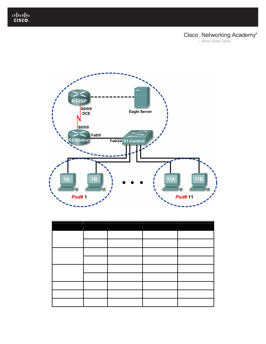
All contents are Copyright © 1992–2007 Cisco Systems, Inc. All rights reserved. This document is Cisco Public Information.
Page 1 of 8
Lab 6.7.2: Examining ICMP Packets
Topology Diagram
Addressing Table
Device
Interface
IP Address
Subnet Mask
Default Gateway
S0/0/0
10.10.10.6
255.255.255.252 N/A
R1-ISP
Fa0/0
192.168.254.253 255.255.255.0
N/A
S0/0/0
10.10.10.5
255.255.255.252 10.10.10.6
R2-Central
Fa0/0
172.16.255.254 255.255.0.0
N/A
N/A
192.168.254.254 255.255.255.0
192.168.254.253
Eagle Server
N/A
172.31.24.254
255.255.255.0
N/A
hostPod#A
N/A
172.16.Pod#.1
255.255.0.0
172.16.255.254
hostPod#B
N/A
172.16.Pod#.2
255.255.0.0
172.16.255.254
S1-Central
N/A
172.16.254.1
255.255.0.0
172.16.255.254

CCNA Exploration
Network Fundamentals: Addressing the Network - IPV4
Lab 6.7.2: Examining ICMP Packets
All contents are Copyright © 1992–2007 Cisco Systems, Inc. All rights reserved. This document is Cisco Public Information.
Page 2 of 8
Learning Objectives
Upon completion of this lab, you will be able to:
•
Understand the format of ICMP packets.
•
Use Wireshark to capture and examine ICMP messages.
Background
The Internet Control Message Protocol (ICMP) was first defined in RFC 792, September, 1981. ICMP
message types were later expanded in RFC 1700. ICMP operates at the TCP/IP Network layer and is
used to exchange information between devices.
ICMP packets serve many uses in today’s computer network. When a router cannot deliver a packet to a
destination network or host, an informational message is returned to the source. Also, the ping and
tracert
commands send ICMP messages to destinations, and destinations respond with ICMP
messages.
Scenario
Using the Eagle 1 Lab, Wireshark captures will be made of ICMP packets between network devices.
Task 1: Understand the Format of ICMP Packets.
Figure 1. ICMP Message Header
Refer to Figure 1, the ICMP header fields common to all ICMP message types. Each ICMP message
starts with an 8-bit Type field, an 8-bit Code field, and a computed 16-bit Checksum. The ICMP message
type describes the remaining ICMP fields. The table in Figure 2 shows ICMP message types from RFC
792:
Value
Meaning
0
Echo Reply
3
Destination Unreachable
4
Source Quench
5
Redirect
8
Echo
11
Time Exceeded
12
Parameter Problem
13
Timestamp
14
Timestamp Reply
15
Information Request
16
Information Reply
Figure 2. ICMP Message Types
Codes provide additional information to the Type field. For example, if the Type field is 3, destination
unreachable, additional information about the problem is returned in the Code field. The table in Figure 3
shows message codes for an ICMP Type 3 message, destination unreachable, from RFC 1700:
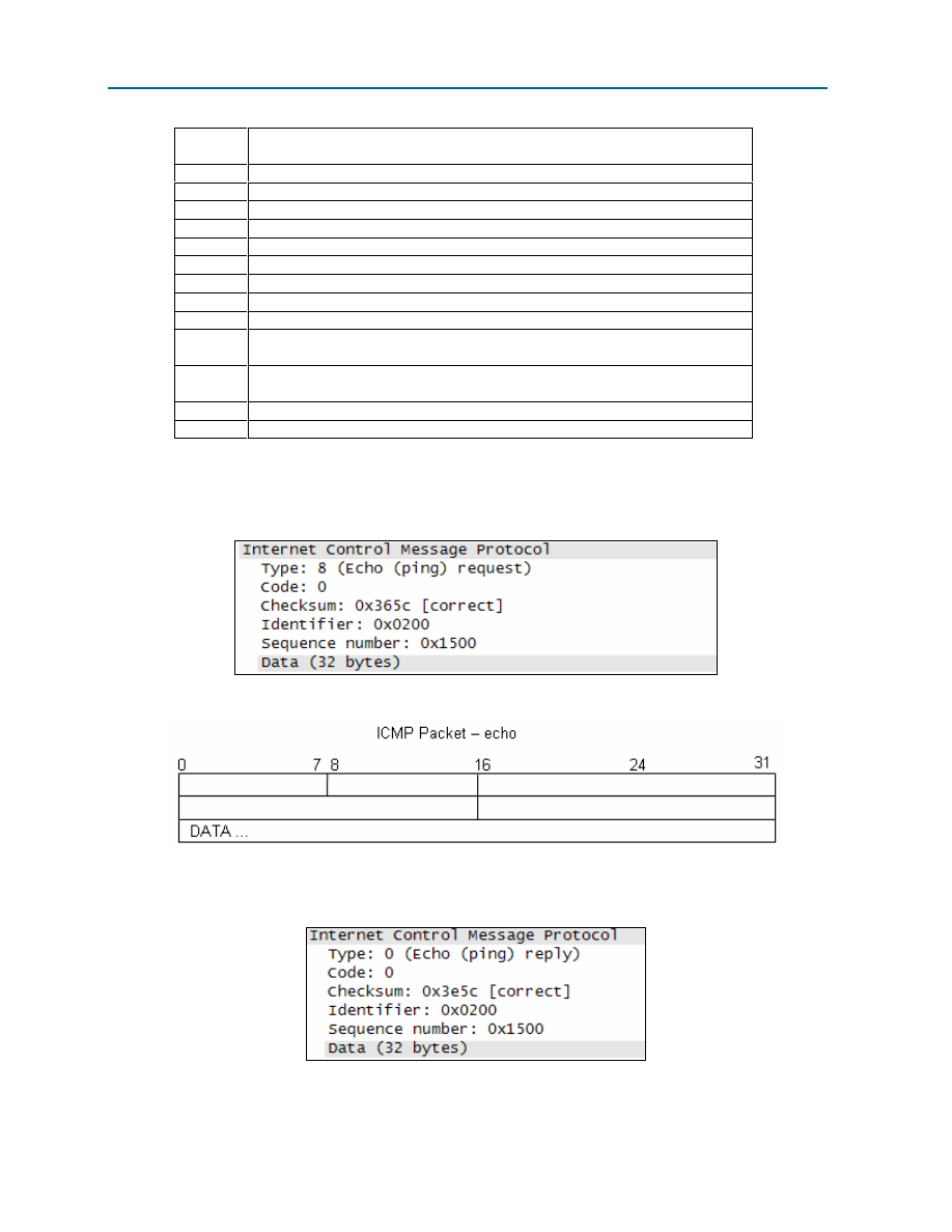
CCNA Exploration
Network Fundamentals: Addressing the Network - IPV4
Lab 6.7.2: Examining ICMP Packets
All contents are Copyright © 1992–2007 Cisco Systems, Inc. All rights reserved. This document is Cisco Public Information.
Page 3 of 8
Code
Value
Meaning
0
Net Unreachable
1
Host Unreachable
2
Protocol Unreachable
3
Port Unreachable
4
Fragmentation Needed and Don't Fragment was Set
5
Source Route Failed
6
Destination Network Unknown
7
Destination Host Unknown
8
Source Host Isolated
9
Communication with Destination Network is
Administratively Prohibited
10
Communication with Destination Host is
Administratively Prohibited
11
Destination Network Unreachable for Type of Service
12
Destination Host Unreachable for Type of Service
Figure 3. ICMP Type 3 Message Codes
Using ICMP message capture shown in Figure 4, fill in the fields for the ICMP packet echo request.
Values beginning with 0x are hexadecimal numbers:
Figure 4. ICMP Packet Echo Request
Using the ICMP message capture shown in Figure 5, fill in the fields for the ICMP packet echo reply:
Figure 5. ICMP Packet Echo Reply
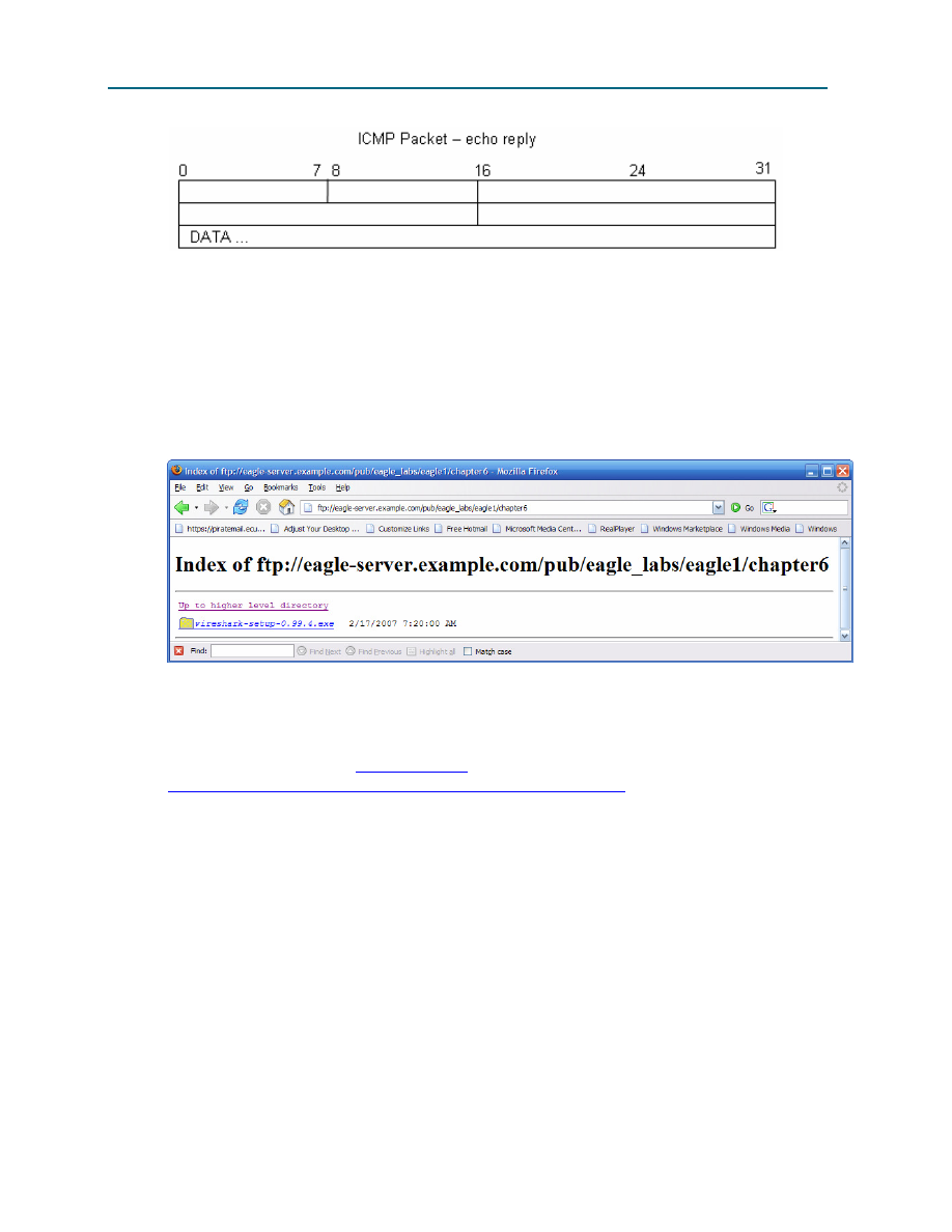
CCNA Exploration
Network Fundamentals: Addressing the Network - IPV4
Lab 6.7.2: Examining ICMP Packets
All contents are Copyright © 1992–2007 Cisco Systems, Inc. All rights reserved. This document is Cisco Public Information.
Page 4 of 8
At the TCP/IP Network layer, communication between devices is not guaranteed. However, ICMP does
provide minimal checks for a reply to match the request. From the information provided in the ICMP
messages above, how does the sender know that the reply is to a specific echo?
___________________________________________________________________________________
___________________________________________________________________________________
Task 2: Use Wireshark to Capture and Examine ICMP Messages.
Figure 6. Wireshark Download Site
If Wireshark has not been loaded on the pod host computer, it can be downloaded from Eagle Server.
1. Open a web browser, URL
FTP://eagle-
server.example.com/pub/eagle_labs/eagle1/chapter6
, as shown in Figure 6.
2. Right-click the Wireshark filename, click Save Link As, and save the file to the pod host
computer.
3. When the file has been downloaded, open and install Wireshark.
Step 1: Capture and evaluate ICMP echo messages to Eagle Server.
In this step, Wireshark will be used to examine ICMP echo messages.
1. Open a Windows terminal on the pod host computer.
2. When ready, start Wireshark capture.
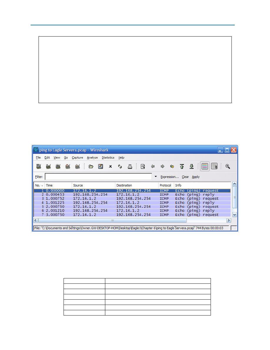
CCNA Exploration
Network Fundamentals: Addressing the Network - IPV4
Lab 6.7.2: Examining ICMP Packets
All contents are Copyright © 1992–2007 Cisco Systems, Inc. All rights reserved. This document is Cisco Public Information.
Page 5 of 8
C:\>
ping eagle-server.example.com
Pinging eagle-server.example.com [192.168.254.254] with 32 bytes of
data:
Reply from 192.168.254.254: bytes=32 time<1ms TTL=63
Reply from 192.168.254.254: bytes=32 time<1ms TTL=63
Reply from 192.168.254.254: bytes=32 time<1ms TTL=63
Reply from 192.168.254.254: bytes=32 time<1ms TTL=63
Ping statistics for 192.168.254.254:
Packets: Sent = 4, Received = 4, Lost = 0 (0% loss),
Approximate round trip times in milli-seconds:
Minimum = 0ms, Maximum = 0ms, Average = 0ms
C:\>
Figure 7. Successful ping Replies from Eagle Server
3. From the Windows terminal, ping Eagle Server. Four successful replies should be received from
Eagle Server, as shown in Figure 7.
4. Stop Wireshark capture. There should be a total of four ICMP echo requests and matching echo
replies, similar to those shown in Figure 8.
Figure 8. Wireshark Capture of ping Requests and Replies
Which network device responds to the ICMP echo request? __________________________________
5. Expand the middle window in Wireshark, and expand the Internet Control Message Protocol
record until all fields are visible. The bottom window will also be needed to examine the Data
field.
6. Record information from the first echo request packet to Eagle Server:
Field
Value
Type
Code
Checksum
Identifier
Sequence number
Data
CCNA Exploration
Network Fundamentals: Addressing the Network - IPV4
Lab 6.7.2: Examining ICMP Packets
All contents are Copyright © 1992–2007 Cisco Systems, Inc. All rights reserved. This document is Cisco Public Information.
Page 6 of 8
Are there 32 bytes of data? _____
7. Record information from the first echo reply packet from Eagle Server:
Field
Value
Type
Code
Checksum
Identifier
Sequence number
Data
Which fields, if any, changed from the echo request?
___________________________________________________________________________________
8. Continue to evaluate the remaining echo requests and replies. Fill in the following information
from each new ping:
Packet
Checksum Identifier
Sequence number
Request # 2
Reply # 2
Request # 3
Reply # 3
Request # 4
Reply # 4
Why did the Checksum values change with each new request?
___________________________________________________________________________________
Step 2: Capture and evaluate ICMP echo messages to 192.168.253.1.
In this step, pings will be sent to a fictitious network and host. The results from the Wireshark capture will
be evaluated—and may be surprising.
Try to ping IP address 192.168.253.1.
C:\>
ping 192.168.253.1
C:\>
ping 192.168.253.1
Pinging 192.168.253.1 with 32 bytes of data:
Reply from 172.16.255.254: Destination host unreachable.
Reply from 172.16.255.254: Destination host unreachable.
Reply from 172.16.255.254: Destination host unreachable.
Reply from 172.16.255.254: Destination host unreachable.
Ping statistics for 192.168.253.1:
Packets: Sent = 4, Received = 4, Lost = 0 (0% loss),
Approximate round trip times in milli-seconds:
Minimum = 0ms, Maximum = 0ms, Average = 0ms
C:\>
Figure 9. Ping Results from a Fictitious Destination
See Figure 9. Instead of a request timeout, there is an echo response.
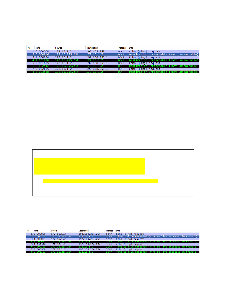
CCNA Exploration
Network Fundamentals: Addressing the Network - IPV4
Lab 6.7.2: Examining ICMP Packets
All contents are Copyright © 1992–2007 Cisco Systems, Inc. All rights reserved. This document is Cisco Public Information.
Page 7 of 8
What network device responds to pings to a fictitious destination?
___________________________________________________________________________________
Figure 10. Wireshark Capture from a Fictitious Destination
Wireshark captures to a fictitious destination are shown in Figure 10. Expand the middle Wireshark
window and the Internet Control Message Protocol record.
Which ICMP message type is used to return information to the sender?
___________________________________________________________________________________
What is the code associated with the message type?
___________________________________________________________________________________
Step 3: Capture and evaluate ICMP echo messages that exceed the TTL value.
In this step, pings will be sent with a low TTL value, simulating a destination that is unreachable. Ping
Eagle Server, and set the TTL value to 1:
C:\>
ping -i 1 192.168.254.254
C:\>
ping -i 1 192.168.254.254
Pinging 192.168.254.254 with 32 bytes of data:
Reply from 172.16.255.254: TTL expired in transit.
Reply from 172.16.255.254: TTL expired in transit.
Reply from 172.16.255.254: TTL expired in transit.
Reply from 172.16.255.254: TTL expired in transit.
Ping statistics for 192.168.254.254:
Packets: Sent = 4, Received = 4, Lost = 0 (0% loss),
Approximate round trip times in milli-seconds:
Minimum = 0ms, Maximum = 0ms, Average = 0ms
C:\>
Figure 11. Ping Results for an Exceeded TTL
See Figure 11, which shows ping replies when the TTL value has been exceeded.
What network device responds to pings that exceed the TTL value?
___________________________________________________________________________________
Figure 12. Wireshark Capture of TTL Value Exceeded

CCNA Exploration
Network Fundamentals: Addressing the Network - IPV4
Lab 6.7.2: Examining ICMP Packets
All contents are Copyright © 1992–2007 Cisco Systems, Inc. All rights reserved. This document is Cisco Public Information.
Page 8 of 8
Wireshark captures to a fictitious destination are shown in Figure 12. Expand the middle Wireshark
window and the Internet Control Message Protocol record.
Which ICMP message type is used to return information to the sender?
___________________________________________________________________________________
What is the code associated with the message type?
___________________________________________________________________________________
Which network device is responsible for decrementing the TTL value?
___________________________________________________________________________________
Task 3: Challenge
Use Wireshark to capture a tracert session to Eagle Server and then to 192.168.254.251. Examine the
ICMP TTL exceeded message. This will demonstrate how the tracert command traces the network
path to the destination.
Task 4: Reflection
The ICMP protocol is very useful when troubleshooting network connectivity issues. Without ICMP
messages, a sender has no way to tell why a destination connection failed. Using the ping command,
different ICMP message type values were captured and evaluated.
Task 5: Clean Up
Wireshark may have been loaded on the pod host computer. If the program must be removed, click Start
> Control Panel > Add or Remove Programs, and scroll down to Wireshark. Click the filename, click
Remove, and follow uninstall instructions.
Remove any Wireshark pcap files that were created on the pod host computer.
Unless directed otherwise by the instructor, turn off power to the host computers. Remove anything that
was brought into the lab, and leave the room ready for the next class.

All contents are Copyright © 1992–2007 Cisco Systems, Inc. All rights reserved. This document is Cisco Public Information.
Page 1 of 4
Activity 6.7.3: IPv4 Address Subnetting Part 1
Learning Objectives
Upon completion of this activity, you will be able to determine network information for a given IP address
and network mask.
Background
This activity is designed to teach how to compute network IP address information from a given IP
address.
Scenario
When given an IP address and network mask, you will be able to determine other information about the
IP address such as:
•
Network address
•
Network broadcast address
•
Total number of host bits
•
Number of hosts
Task 1: For a given IP address, Determine Network Information.
Given:
Host IP Address 172.25.114.250
Network Mask
255.255.0.0 (/16)
Find:
Network Address
Network Broadcast Address
Total Number of Host Bits
Number of Hosts
Step 1: Translate Host IP address and network mask into binary notation.
Convert the host IP address and network mask to binary:
172
25
114
250
IP Address
10101100 11001000 01110010
11111010
Network Mask
11111111 11111111 00000000
00000000
255
255
0
0
Step 2: Determine the network address.
1. Draw a line under the mask.
2. Perform a bit-wise AND operation on the IP address and the subnet mask.

CCNA Exploration
Network Fundamentals:
Addressing the Network - IPv4
Activity 6.7.3: IPv4 Address Subnetting Part 1
All contents are Copyright © 1992–2007 Cisco Systems, Inc. All rights reserved. This document is Cisco Public Information.
Page 2 of 4
Note: 1 AND 1 results in a 1; 0 AND anything results in a 0.
3. Express the result in dotted decimal notation.
4. The result is the network address for this host IP address, which is 172.25.0.0.
172
25
114
250
IP Address
10101100 11001000 01110010 11111010
Subnet Mask
11111111 11111111 00000000 00000000
Network Address
10101100 11001000 00000000 00000000
172
25
0
0
Step 3: Determine the broadcast address for the network address
The network mask separates the network portion of the address from the host portion. The network
address has all 0s in the host portion of the address and the broadcast address has all 1s in the host
portion of the address.
172
25
0
0
Network Add. 10101100 11001000 00000000 00000000
Mask
11111111 11111111 00000000 00000000
Broadcast.
10101100 11001000 11111111 11111111
172
25
255
255
By counting the number of host bits, we can determine the total number of usable hosts for this network.
Host bits: 16
Total number of hosts:
2
16
= 65,536
65,536 – 2 = 65,534 (addresses that cannot use the all 0s address, network address, or the all 1s
address, broadcast address.)
Add this information to the table:
Host IP Address
172.25.114.250
Network Mask
255.255.0.0 (/16)
Network Address
Network Broadcast Address
Total Number of Host Bits
Number of Hosts

CCNA Exploration
Network Fundamentals:
Addressing the Network - IPv4
Activity 6.7.3: IPv4 Address Subnetting Part 1
All contents are Copyright © 1992–2007 Cisco Systems, Inc. All rights reserved. This document is Cisco Public Information.
Page 3 of 4
Task 2: Challenge
For all problems:
Create a Subnetting Worksheet to show and record all work for each problem.
Problem 1
Host IP Address
172.30.1.33
Network Mask
255.255.0.0
Network Address
Network Broadcast Address
Total Number of Host Bits
Number of Hosts
Problem 2
Host IP Address
172.30.1.33
Network Mask
255.255.255.0
Network Address
Network Broadcast Address
Total Number of Host Bits
Number of Hosts
Problem 3
Host IP Address
192.168.10.234
Network Mask
255.255.255.0
Network Address
Network Broadcast Address
Total Number of Host Bits
Number of Hosts
Problem 4
Host IP Address
172.17.99.71
Network Mask
255.255.0.0
Network Address
Network Broadcast Address
Total Number of Host Bits
Number of Hosts

CCNA Exploration
Network Fundamentals:
Addressing the Network - IPv4
Activity 6.7.3: IPv4 Address Subnetting Part 1
All contents are Copyright © 1992–2007 Cisco Systems, Inc. All rights reserved. This document is Cisco Public Information.
Page 4 of 4
Problem 5
Host IP Address
192.168.3.219
Network Mask
255.255.0.0
Network Address
Network Broadcast Address
Total Number of Host Bits
Number of Hosts
Problem 6
Host IP Address
192.168.3.219
Network Mask
255.255.255.224
Network Address
Network Broadcast Address
Total Number of Host Bits
Number of Hosts
Task 3: Clean Up
Remove anything that was brought into the lab, and leave the room ready for the next class.

All contents are Copyright © 1992–2007 Cisco Systems, Inc. All rights reserved. This document is Cisco Public Information.
Page 1 of 8
Activity 6.7.4: IPv4 Address Subnetting Part 2
Learning Objectives
Upon completion of this activity, you will be able to determine subnet information for a given IP address
and subnetwork mask.
Background
Borrowing Bits
How many bits must be borrowed to create a certain number of subnets or a certain number of hosts per
subnet?
Using this chart, it is easy to determine the number of bits that must be borrowed.
Things to remember:
•
Subtract 2 for the usable number of hosts per subnet, one for the subnet address and one for the
broadcast address of the subnet.
2
10
2
9
2
8
2
7
2
6
2
5
2
4
2
3
2
2
2
1
2
0
1,024 512
256 128
64 32 16 8
4 2
1
Number of bits borrowed:
10
9
8
7
6 5
4
3
2 1
1
1,024 512
256 128
64 32 16 8
4 2
1
Hosts or Subnets
Possible Subnet Mask Values
Because subnet masks must be contiguous 1’s followed by contiguous 0’s, the converted dotted decimal
notation can contain one of a certain number of values:
Dec.
Binary
255 11111111
254 11111110
252 11111100
248 11111000
240 11110000
224 11100000
192 11000000
128 10000000
0
00000000

CCNA Exploration
Network Fundamentals:
Addressing the Network - IPv4
Activity 6.7.4: IPv4 Address Subnetting Part 2
All contents are Copyright © 1992–2007 Cisco Systems, Inc. All rights reserved. This document is Cisco Public Information.
Page 2 of 8
Scenario
When given an IP address, network mask, and subnetwork mask, you will be able to determine other
information about the IP address such as:
•
The subnet address of this subnet
•
The broadcast address of this subnet
•
The range of host addresses for this subnet
•
The maximum number of subnets for this subnet mask
•
The number of hosts for each subnet
•
The number of subnet bits
•
The number of this subnet
Task 1: For a Given IP Address and Subnet Mask, Determine Subnet Information.
Given:
Host IP Address 172.25.114.250
Network Mask
255.255.0.0 (/16)
Subnet Mask
255.255.255.192 (/26)
Find:
Number of Subnet Bits
Number of Subnets
Number of Host Bits per Subnet
Number of Usable Hosts per Subnet
Subnet Address for this IP Address
IP Address of First Host on this Subnet
IP Address of Last Host on this Subnet
Broadcast Address for this Subnet
Step 1: Translate host IP address and subnet mask into binary notation.
172
25
114
250
IP Address
10101100 11001000 01110010 11111010
11111111 11111111 11111111 11000000
Subnet Mask
255
255
255
192
Step 2: Determine the network (or subnet) where this host address belongs.
1. Draw a line under the mask.
2. Perform a bit-wise AND operation on the IP Address and the Subnet Mask.
Note: 1 AND 1 results in a 1’ 0 AND anything results in a 0.
3. Express the result in dotted decimal notation.
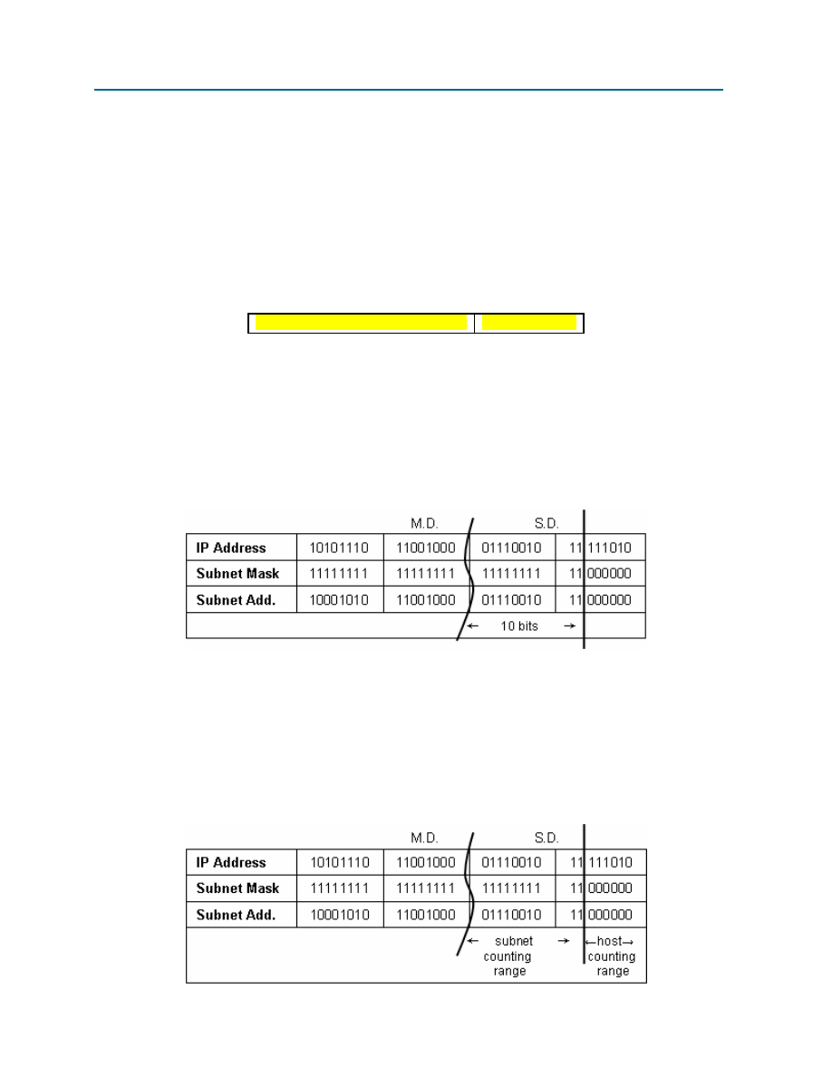
CCNA Exploration
Network Fundamentals:
Addressing the Network - IPv4
Activity 6.7.4: IPv4 Address Subnetting Part 2
All contents are Copyright © 1992–2007 Cisco Systems, Inc. All rights reserved. This document is Cisco Public Information.
Page 3 of 8
4. The result is the Subnet Address of this Subnet, which is 172.25.114.192
172
25
114
250
IP Address
10101100 11001000 01110010 11111010
Subnet Mask
11111111 11111111 11111111 11000000
Subnet Address
10101100 11001000 01110010 11000000
172
25
114
192
Add this information to the table:
Subnet Address for this IP Address 172.25.114.192
Step 3: Determine which bits in the address contain network information and which contain host
information.
1. Draw the Major Divide (M.D.) as a wavy line where the 1s in the major network mask end (also
the mask if there was no subnetting). In our example, the major network mask is 255.255.0.0, or
the first 16 left-most bits.
2. Draw the Subnet Divide (S.D.) as a straight line where the 1s in the given subnet mask end. The
network information ends where the 1s in the mask end.
3. The result is the Number of Subnet Bits, which can be determined by simply counting the number
of bits between the M.D. and S.D., which in this case is 10 bits.
Step 4: Determine the bit ranges for subnets and hosts.
1. Label the subnet counting range between the M.D. and the S.D. This range contains the bits that
are being incremented to create the subnet numbers or addresses.
2. Label the host counting range between the S.D. and the last bits at the end on the right. This
range contains the bits that are being incremented to create the host numbers or addresses.
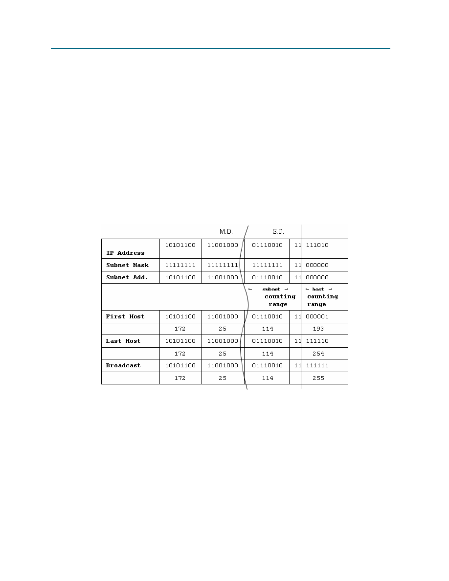
CCNA Exploration
Network Fundamentals:
Addressing the Network - IPv4
Activity 6.7.4: IPv4 Address Subnetting Part 2
All contents are Copyright © 1992–2007 Cisco Systems, Inc. All rights reserved. This document is Cisco Public Information.
Page 4 of 8
Step 5: Determine the range of host addresses available on this subnet and the broadcast address
on this subnet.
1. Copy down all of the network/subnet bits of the network address (that is, all bits before the S.D.).
2. In the host portion (to the right of the S.D.), make the host bits all 0s except for the right-most bit
(or least significant bit), which you make a 1. This gives us the first host IP address on this
subnet, which is the first part of the result for Range of Host Addresses for This Subnet, which in
the example is 172.25.114.193.
3. Next, in the host portion (to the right of the S.D.), make the host bits all 1s except for the right-
most bit (or least significant bit), which you make a 0. This gives us the last host IP address on
this subnet, which is the last part of the result for Range of Host Addresses for This Subnet,
which in the example is 172.25.114.254.
4. In the host portion (to the right of the S.D.), make the host bits all 1s. This gives us the broadcast
IP address on this subnet. This is the result for Broadcast Address of This Subnet, which in the
example is 172.25.114.255.

CCNA Exploration
Network Fundamentals:
Addressing the Network - IPv4
Activity 6.7.4: IPv4 Address Subnetting Part 2
All contents are Copyright © 1992–2007 Cisco Systems, Inc. All rights reserved. This document is Cisco Public Information.
Page 5 of 8
Let’s add some of this information to our table:
Host IP Address
172.25.114.250
Major Network Mask
255.255.0.0 (/16)
Major (Base) Network Address
172.25.0.0
Major Network Broadcast Address
172.25.255.255
Total Number of Host Bits
Number of Hosts
16 bits or 2
16
or 65,536 total hosts
65,536 – 2 = 65,534 usable hosts
Subnet Mask
255.255.255.192 (/26)
Number of Subnet Bits
Number of Subnets
Number of Host Bits per Subnet
Number of Usable Hosts per Subnet
Subnet Address for this IP Address
IP Address of First Host on this Subnet
IP Address of Last Host on this Subnet
Broadcast Address for this Subnet
Step 6: Determine the number of subnets.
The number of subnets is determined by how many bits are in the subnet counting range (in this example,
10 bits).
Use the formula 2
n
, where n is the number of bits in the subnet counting range.
1. 2
10
= 1024
Number of Subnet Bits
Number of Subnets
(all 0s used, all 1s not used)
10 bits
2
10
= 1024 subnets
Step 7: Determine the number usable hosts per subnet.
The number of hosts per subnet is determined by the number of host bits (in this example, 6 bits) minus 2
(1 for the subnet address and 1 for the broadcast address of the subnet).
2
6
– 2 = 64 – 2 = 62 hosts per subnet
Number of Host Bits per Subnet
Number of Usable Hosts per Subnet
6 bits
2
6
– 2 = 64
–
2 = 62 hosts per subnet

CCNA Exploration
Network Fundamentals:
Addressing the Network - IPv4
Activity 6.7.4: IPv4 Address Subnetting Part 2
All contents are Copyright © 1992–2007 Cisco Systems, Inc. All rights reserved. This document is Cisco Public Information.
Page 6 of 8
Step 8: Final Answers
Host IP Address
172.25.114.250
Subnet Mask
255.255.255.192 (/26)
Number of Subnet Bits
Number of Subnets
26 bits
2
10
= 1024 subnets
Number of Host Bits per Subnet
Number of Usable Hosts per Subnet
6 bits
2
6
– 2 = 64
–
2 = 62 hosts per subnet
Subnet Address for this IP Address
172.25.114.192
IP Address of First Host on this Subnet
172.25.114.193
IP Address of Last Host on this Subnet
172.25.114.254
Broadcast Address for this Subnet
172.25.114.255
Task 2: Challenge.
For all problems:
Create a Subnetting Worksheet to show and record all work for each problem.
Problem 1
Host IP Address
172.30.1.33
Subnet Mask
255.255.255.0
Number of Subnet Bits
Number of Subnets
Number of Host Bits per Subnet
Number of Usable Hosts per Subnet
Subnet Address for this IP Address
IP Address of First Host on this Subnet
IP Address of Last Host on this Subnet
Broadcast Address for this Subnet
Problem 2
Host IP Address
172.30.1.33
Subnet Mask
255.255.255.252
Number of Subnet Bits
Number of Subnets
Number of Host Bits per Subnet
Number of Usable Hosts per Subnet
Subnet Address for this IP Address
IP Address of First Host on this Subnet
IP Address of Last Host on this Subnet
Broadcast Address for this Subnet

CCNA Exploration
Network Fundamentals:
Addressing the Network - IPv4
Activity 6.7.4: IPv4 Address Subnetting Part 2
All contents are Copyright © 1992–2007 Cisco Systems, Inc. All rights reserved. This document is Cisco Public Information.
Page 7 of 8
Problem 3
Host IP Address
192.192.10.234
Subnet Mask
255.255.255.0
Number of Subnet Bits
Number of Subnets
Number of Host Bits per Subnet
Number of Usable Hosts per Subnet
Subnet Address for this IP Address
IP Address of First Host on this Subnet
IP Address of Last Host on this Subnet
Broadcast Address for this Subnet
Problem 4
Host IP Address
172.17.99.71
Subnet Mask
255.255.0.0
Number of Subnet Bits
Number of Subnets
Number of Host Bits per Subnet
Number of Usable Hosts per Subnet
Subnet Address for this IP Address
IP Address of First Host on this Subnet
IP Address of Last Host on this Subnet
Broadcast Address for this Subnet
Problem 5
Host IP Address
192.168.3.219
Subnet Mask
255.255.255.0
Number of Subnet Bits
Number of Subnets
Number of Host Bits per Subnet
Number of Usable Hosts per Subnet
Subnet Address for this IP Address
IP Address of First Host on this Subnet
IP Address of Last Host on this Subnet
Broadcast Address for this Subnet

CCNA Exploration
Network Fundamentals:
Addressing the Network - IPv4
Activity 6.7.4: IPv4 Address Subnetting Part 2
All contents are Copyright © 1992–2007 Cisco Systems, Inc. All rights reserved. This document is Cisco Public Information.
Page 8 of 8
Problem 6
Host IP Address
192.168.3.219
Subnet Mask
255.255.255.252
Number of Subnet Bits
Number of Subnets
Number of Host Bits per Subnet
Number of Usable Hosts per Subnet
Subnet Address for this IP Address
IP Address of First Host on this Subnet
IP Address of Last Host on this Subnet
Broadcast Address for this Subnet
Task 3: Clean Up
Remove anything that was brought into the lab, and leave the room ready for the next class.
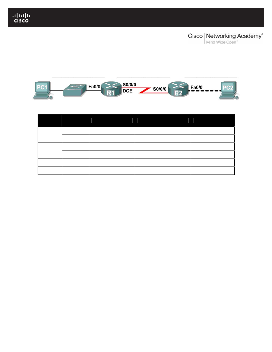
Lab 6.7.5: Subnet and Router Configuration
Topology Diagram
Addressing Table
Device
Interface
IP Address
Subnet Mask
Default Gateway
Fa0/0
N/A
R1
S0/0/0
N/A
Fa0/0
N/A
R2
S0/0/0
N/A
PC1 NIC
PC2 NIC
Learning Objectives
Upon completion of this lab, you will be able to:
• Subnet an address space given requirements.
• Assign appropriate addresses to interfaces and document.
• Configure and activate Serial and FastEthernet interfaces.
• Test and verify configurations.
• Reflect upon and document the network implementation.
Scenario
In this lab activity, you will design and apply an IP addressing scheme for the topology shown in the
Topology Diagram. You will be given one address block that you must subnet to provide a logical
addressing scheme for the network. The routers will then be ready for interface address configuration
according to your IP addressing scheme. When the configuration is complete, verify that the network is
working properly.
All contents are Copyright © 1992–2007 Cisco Systems, Inc. All rights reserved. This document is Cisco Public Information.
Page 1 of 3

CCNA Exploration
Network Fundamentals: Addressing the Network - IPV4
Lab 6.7.1: Subnet and Router Configuration
Task 1: Subnet the Address Space.
Step 1: Examine the network requirements.
You have been given the 192.168.1.0/24 address space to use in your network design. The network
consists of the following segments:
• The network connected to router R1 will require enough IP addresses to support 15 hosts.
• The network connected to router R2 will require enough IP addresses to support 30 hosts.
• The link between router R1 and router R2 will require IP addresses at each end of the link.
Step 2: Consider the following questions when creating your network design.
How many subnets are needed for this network? ____________________
What is the subnet mask for this network in dotted decimal format? ____________________
What is the subnet mask for the network in slash format? ____________________
How many usable hosts are there per subnet? ____________________
Step 3: Assign subnetwork addresses to the Topology Diagram.
1. Assign subnet 1 to the network attached to R1.
2. Assign subnet 2 to the link between R1 and R2.
3. Assign subnet 3 to the network attached to R2.
Task 2: Determine Interface Addresses.
Step 1: Assign appropriate addresses to the device interfaces.
1. Assign the first valid host address in subnet 1 to the LAN interface on R1.
2. Assign the last valid host address in subnet 1 to PC1.
3. Assign the first valid host address in subnet 2 to the WAN interface on R1.
4. Assign the last valid host address in subnet 2 to the WAN interface on R2.
5. Assign the first valid host address in subnet 3 to the LAN interface of R2.
6. Assign the last valid host address in subnet 3 to PC2.
Step 2: Document the addresses to be used in the table provide under the Topology Diagram.
Task 3: Configure the Serial and FastEthernet Addresses.
Step 1: Configure the router interfaces.
Configure the interfaces on the R1 and R2 routers with the IP addresses from your network design.
Please note, to complete the activity in Packet Tracer you will be using the Config Tab. When you have
finished, be sure to save the running configuration to the NVRAM of the router.
Step 2: Configure the PC interfaces.
Configure the Ethernet interfaces of PC1 and PC2 with the IP addresses and default gateways from your
network design.
All contents are Copyright © 1992–2007 Cisco Systems, Inc. All rights reserved. This document is Cisco Public Information.
Page 2 of 3

CCNA Exploration
Network Fundamentals: Addressing the Network - IPV4
Lab 6.7.1: Subnet and Router Configuration
Task 4: Verify the Configurations.
Answer the following questions to verify that the network is operating as expected.
From the host attached to R1, is it possible to ping the default gateway? __________
From the host attached to R2, is it possible to ping the default gateway? __________
From the router R1, is it possible to ping the Serial 0/0/0 interface of R2? __________
From the router R2, is it possible to ping the Serial 0/0/0 interface of R1? __________
Task 5: Reflection
Are there any devices on the network that cannot ping each other?
__________________________________________________________________________
__________________________________________________________________________
What is missing from the network that is preventing communication between these devices?
__________________________________________________________________________
__________________________________________________________________________
All contents are Copyright © 1992–2007 Cisco Systems, Inc. All rights reserved. This document is Cisco Public Information.
Page 3 of 3
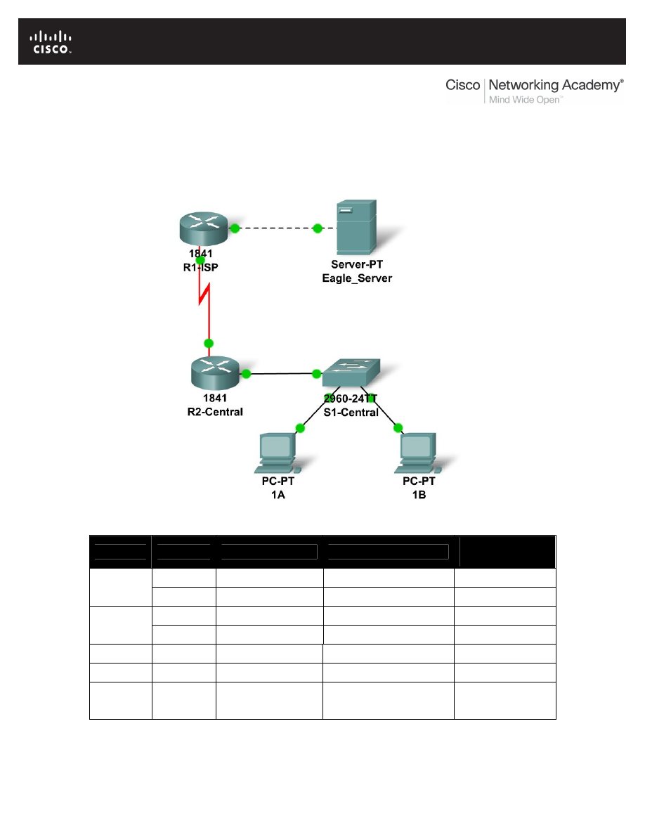
All contents are Copyright © 1992–2007 Cisco Systems, Inc. All rights reserved. This document is Cisco Public Information.
Page 1 of 3
6.8.1: Skills Integration Challenge-Planning Subnets and
Configuring IP Addresses
Topology Diagram
Addressing Table
Device
Interface
IP Address
Subnet Mask
Default
Gateway
Fa0/0
N/A
R1-ISP
S0/0/0
N/A
Fa0/0
R2-
Central
S0/0/0
PC 1A
NIC
PC 1B
NIC
Eagle
Server
NIC

CCNA Exploration
Network Fundamentals:
Addressing the Network - IPv4
6.8.1: Skills Integration Challenge-Planning Subnets and Configuring IP Addresses
All contents are Copyright © 1992–2007 Cisco Systems, Inc. All rights reserved. This document is Cisco Public Information.
Page 2 of 3
Learning Objectives
•
IP Subnet Planning
o
Practice your subnetting skills.
•
Build the Network.
o
Connect devices with Ethernet and serial cables.
•
Configure the network.
o
Apply your subnetting scheme to server, PCs, and router interfaces; configure
services and static routing.
•
Test the network.
o
Using ping, trace, web traffic, Inspect tool
Background
You have been asked to implement the standard lab topology, but with a new IP addressing
scheme. You will use many of the skills you have learned to this point in the course.
Task 1: IP Subnet Planning
You have been given an IP address block of 192.168.23.0 /24. You must provide for existing
networks as well as future growth.
Subnet assignments are:
•
1st subnet, existing student LAN (off of router R2-Central), up to 60 hosts;
•
2nd subnet, future student LAN, up to 28 hosts;
•
3rd subnet, existing ISP LAN, up to 12 hosts;
•
4th subnet, future ISP LAN, up to 8 hosts;
•
5th subnet, existing WAN, point-to-point link;
•
6th subnet, future WAN, point-to-point link;
•
7th subnet, future WAN, point-to-point link.
Interface IP addresses:
•
For the server, configure the second highest usable IP address on the existing ISP LAN
subnet.
•
For R1-ISP's Fa0/0 interface, configure the highest usable IP address on the existing ISP
LAN subnet.
•
For R1-ISP's S0/0/0 interface, configure the highest usable address on the existing WAN
subnet.
•
For R2-Central's S0/0/0 interface, use the lowest usable address on the existing WAN
subnet.
•
For R2-Central's Fa0/0 interface, use the highest usable address on the existing student
LAN subnet.
•
For hosts 1A and 1B, use the first 2 IP addresses (two lowest usable addresses) on the
existing student LAN subnet.

CCNA Exploration
Network Fundamentals:
Addressing the Network - IPv4
6.8.1: Skills Integration Challenge-Planning Subnets and Configuring IP Addresses
All contents are Copyright © 1992–2007 Cisco Systems, Inc. All rights reserved. This document is Cisco Public Information.
Page 3 of 3
Additional configurations:
•
For PCs 1A and 1B, in addition to IP configuration, configure them to use DNS services.
•
For the server, enable DNS services, use the domain name eagle-server.example.com,
and enable HTTP services.
•
For R1-ISP router serial interface, you will need to set the clock rate (a timing mechanism
required on the DCE end of serial links) to 64000.
•
No clock rate is needed on the DTE side, in this case R2-Central's serial interface.
Task 2: Finish Building the Network in Packet Tracer.
Add cables where missing.
•
Connect a serial DCE cable to R1-ISP S0/0/0, with the other end to R2-Central S0/0/0.
•
Connect PC 1A to the first FastEthernet port on switch S1-Central.
•
Connect PC 1B to the second FastEthernet port on switch S1-Central.
•
Connect interface Fa0/0 on router R2-Central to the highest FastEthernet port on switch
S1-Central.
•
For all devices, make sure the power is on to the device and the interfaces.
Task 3: Configure the Network.
You will need to configure the server, both routers, and the two PCs. You will not need to
configure the switch nor do you need the IOS CLI to configure the routers. Part of the router
configuration has already been done for you: all you must do is configure the static routes and the
interfaces via the GUI. The static route on R1-ISP should point to the existing student LAN subnet
via R2-Central's serial interface IP address; the static route on R2-Central should be a default
static route which points via R1-ISP's serial interface IP address. These procedures were
explained in the Chapter 5 Skills Integration Challenge.
Task 4: Test the Network.
Use ping, trace, web traffic, and the Inspect tool. Trace packet flow in simulation mode, with
HTTP, DNS, TCP, UDP, and ICMP viewable, to test your understanding of how the network is
operating.
Reflection
Reflect upon how much you have learned so far! Practicing IP subnetting skills and networking
building, configuration and testing skills will serve you well throughout your networking courses.
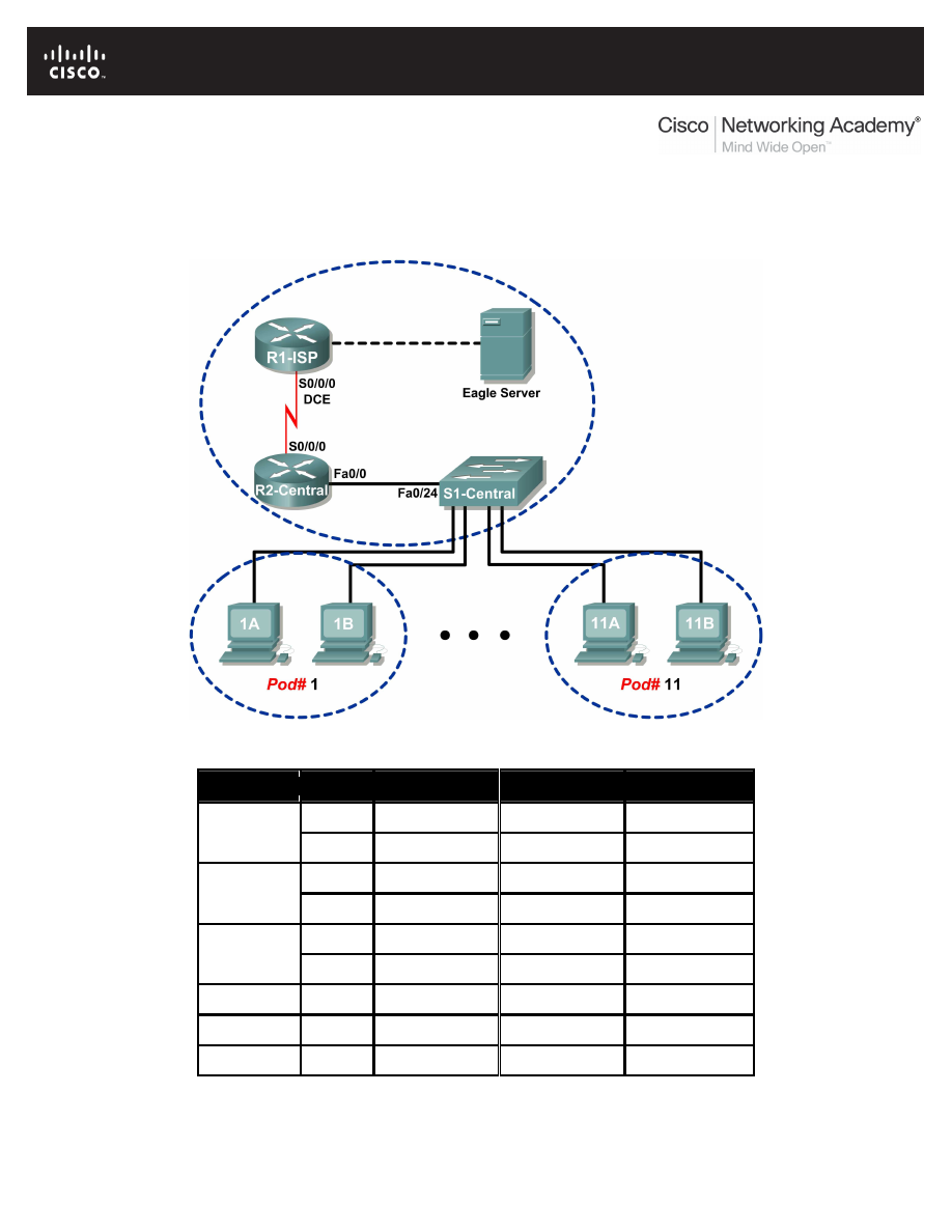
All contents are Copyright © 1992–2007 Cisco Systems, Inc. All rights reserved. This document is Cisco Public Information.
Page 1 of 7
Lab 7.5.2: Frame Examination
Topology Diagram
Addressing Table
Device
Interface IP Address
Subnet Mask
Default Gateway
S0/0/0
10.10.10.6
255.255.255.252 N/A
R1-ISP
Fa0/0
192.168.254.253 255.255.255.0
N/A
S0/0/0
10.10.10.5
255.255.255.252 10.10.10.6
R2-Central
Fa0/0
172.16.255.254 255.255.0.0
N/A
N/A
192.168.254.254 255.255.255.0
192.168.254.253
Eagle Server
N/A
172.31.24.254
255.255.255.0
N/A
hostPod#A
N/A
172.16.Pod#.1
255.255.0.0
172.16.255.254
hostPod#B
N/A
172.16.Pod#.2
255.255.0.0
172.16.255.254
S1-Central
N/A
172.16.254.1
255.255.0.0
172.16.255.254

CCNA Exploration
Network Fundamentals: Data Link Layer
Lab 7.5.2 Frame Examination
All contents are Copyright © 1992–2007 Cisco Systems, Inc. All rights reserved. This document is Cisco Public Information.
Page 2 of 7
Learning Objectives
Upon completion of this lab, you will be able to:
•
Explain the header fields in an Ethernet II frame.
•
Use Wireshark to capture and analyze Ethernet II frames.
Background
When upper layer protocols communicate with each other, data flows down the OSI layers and is
encapsulated into a Layer 2 frame. The frame composition is dependent on the media access type. For
example, if the upper layer protocol is TCP/IP and the media access is Ethernet, then the Layer 2 frame
encapsulation will be Ethernet II.
When learning about Layer 2 concepts, it is helpful to analyze frame header information. The Ethernet II
frame header will be examined in this lab. Ethernet II frames can support various upper layer protocols,
such as TCP/IP.
Scenario
Wireshark will be used to capture and analyze Ethernet II frame header fields. If Wireshark has not been
loaded on the host pod computer, it can be downloaded from URL
ftp://eagle-
server.example.com/pub/eagle_labs/eagle1/chapter7/
, file wireshark-setup-
0.99.4.exe
.
The Windows ping command will be used to generate network traffic for Wireshark to capture.
Task 1: Explain the Header Fields in an Ethernet II Frame.
The format for an Ethernet II frame is shown in Figure 1.
Figure 1. Ethernet II Frame Format
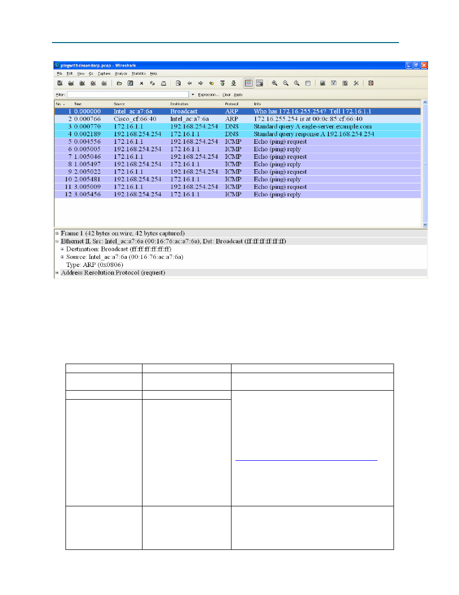
CCNA Exploration
Network Fundamentals: Data Link Layer
Lab 7.5.2 Frame Examination
All contents are Copyright © 1992–2007 Cisco Systems, Inc. All rights reserved. This document is Cisco Public Information.
Page 3 of 7
Figure 2. Wireshark Capture of the ping Command
In Figure 2, the Panel List window shows a Wireshark capture of the ping command between a pod host
computer and Eagle Server. The session begins with the ARP protocol querying for the MAC address of
the Gateway router, followed by a DNS query. Finally, the ping command issues echo requests.
In Figure 2, the Packet Details window shows Frame 1 detail information. Using this window, the following
Ethernet II frame information can be obtained:
Field
Value
Description
Preamble
Not shown in capture.
This field contains synchronizing bits,
processed by the NIC hardware.
Destination Address
ff:ff:ff:ff:ff:ff
Source Address
00:16:76:ac:a7:6a
Layer 2 addresses for the frame. Each
address is 48 bits long, or 6 bytes, expressed
as 12 hexadecimal digits, 0-9,A-F.
A common format is 12:34:56:78:9A:BC.
The first six hex numbers indicate the
manufacturer of the network interface card
(NIC). Refer to
http://www.neotechcc.org/forum/macid.htm
for
a list of vendor codes. The last six hex digits,
ac:a7:6a
, are the serial number of the NIC.
The destination address may be a broadcast
which contains all 1s or unicast. The source
address is always unicast.
Frame Type
0x0806
For Ethernet II frames, this field contains a
hexadecimal value that is used to indicate the
type of upper layer protocol in the data field.
There are numerous upper layer protocols
supported by Ethernet II. Two common frame

CCNA Exploration
Network Fundamentals: Data Link Layer
Lab 7.5.2 Frame Examination
All contents are Copyright © 1992–2007 Cisco Systems, Inc. All rights reserved. This document is Cisco Public Information.
Page 4 of 7
Field
Value
Description
types are:
Value Description
0x0800
IPv4 Protocol
0x0806
Address resolution
protocol (ARP)
Data
ARP
Contains the encapsulated upper level
protocol. The data field is between 46 – 1500
bytes.
FCS
Not shown in capture.
Frame Check Sequence, used by the NIC to
identify errors during transmission. The value
is computed by the sending machine,
encompassing frame addresses, type, and
data field. It is verified by the receiver.
What is the significance of all 1s in the destination address field?
______________________________________________________________________________
______________________________________________________________________________
From the information contained in the Packet List window for the first frame, answer the following
questions about the destination and source MAC address:
Destination Address:
MAC address:
____________________
NIC manufacturer: ____________________
NIC serial number: ____________________
Source Address:
MAC address:
____________________
NIC manufacturer: ____________________
NIC serial number: ____________________
From the information contained in the Packet List window for the second frame, answer the following
questions about the destination and source MAC address:
Destination Address:
MAC address:
____________________
NIC manufacturer: ____________________
NIC serial number: ____________________
Source Address:
MAC address:
____________________
NIC manufacturer: ____________________
NIC serial number: ____________________

CCNA Exploration
Network Fundamentals: Data Link Layer
Lab 7.5.2 Frame Examination
All contents are Copyright © 1992–2007 Cisco Systems, Inc. All rights reserved. This document is Cisco Public Information.
Page 5 of 7
Figure 3. Frame 3 Fields
Figure 3 contains an exploded view of the Frame 3 Wireshark capture. Use the information to complete
the following table:
Field
Value
Preamble
Destination Address
Source Address
Frame Type
Data
FCS
In the following task, Wireshark will be used to capture and analyze packets captured on the pod host
computer.
Task 2: Use Wireshark to Capture and Analyze Ethernet II Frames.
Step 1: Configure Wireshark for packet captures.
Prepare Wireshark for captures. Click Capture > Interfaces, and then click the start button that
corresponds to the 172.16.x.y interface IP address. This will begin the packet capture.
Step 2: Start a ping to Eagle Server and capture the session.
Open a Windows terminal window. Click Start > Run, type cmd, and click OK.
Microsoft Windows XP [Version 5.1.2600]
(C) Copyright 1985-2001 Microsoft Corp.
C:\> ping eagle-server.example.com
Pinging eagle-server.example.com [192.168.254.254] with 32 bytes of
data:
Reply from 192.168.254.254: bytes=32 time<1ms TTL=62
Reply from 192.168.254.254: bytes=32 time<1ms TTL=62
Reply from 192.168.254.254: bytes=32 time<1ms TTL=62
Reply from 192.168.254.254: bytes=32 time<1ms TTL=62
Ping statistics for 192.168.254.254:
Packets: Sent = 4, Received = 4, Lost = 0 (0% loss),
Approximate round trip times in milli-seconds:
Minimum = 0ms, Maximum = 0ms, Average = 0ms
C:\>
Figure 4. Ping to eagle-server.example.com

CCNA Exploration
Network Fundamentals: Data Link Layer
Lab 7.5.2 Frame Examination
All contents are Copyright © 1992–2007 Cisco Systems, Inc. All rights reserved. This document is Cisco Public Information.
Page 6 of 7
Ping eagle-server.example.com, as shown in Figure 4. When the command has finished execution, stop
Wireshark captures.
Step 3: Analyze the Wireshark capture.
The Wireshark Packet List window should start with an ARP request and reply for the MAC address of the
Gateway. Next, a DNS request is made for the IP address of eagle-server.example.com. Finally, the
ping
command is executed. Your capture should look similar to the one shown in Figure 2.
Use your Wireshark capture of the ping command to answer the following questions:
Pod computer MAC address information:
MAC address:
____________________
NIC manufacturer: ____________________
NIC serial number: ____________________
R2-Central MAC address information:
MAC address:
____________________
NIC manufacturer: ____________________
NIC serial number: ____________________
A student from another school would like to know the MAC address for Eagle Server. What would
you tell the student?
What is the Ethernet II frame type value for an ARP Request? ____________________
What is the Ethernet II frame type value for an ARP Reply? ____________________
What is the Ethernet II frame type value for a DNS query? ____________________
What is the Ethernet II frame type value for a DNS query response? ____________________
What is the Ethernet II frame type value for an ICMP echo? ____________________
What is the Ethernet II frame type value for an ICMP echo reply? ____________________
Task 3: Challenge
Use Wireshark to capture sessions from other TCP/IP protocols, such as FTP and HTTP. Analyze the
captured packets, and verify that the Ethernet II frame type remains 0x0800.
Task 4: Reflection
In this lab, Ethernet II frame header information was examined. A preamble field contains seven bytes of
alternating 0101 sequences, and one byte that signals the beginning of the frame, 01010110.
Destination and source MAC addresses each contain 12 hex digits. The first six hex digits contain the
manufacturer of the NIC, and the last six hex digits contain the NIC serial number. If the frame is a
broadcast, the destination MAC address contains all 1s. A 4-byte frame type field contains a value that
indicates the protocol in the data field. For IPv4, the value is 0x0800. The data field is variable and
contains the encapsulated upper layer protocol. At the end of a frame, a 4-byte FCS value is used to
verify that there were no errors during transmission.

CCNA Exploration
Network Fundamentals: Data Link Layer
Lab 7.5.2 Frame Examination
All contents are Copyright © 1992–2007 Cisco Systems, Inc. All rights reserved. This document is Cisco Public Information.
Page 7 of 7
Task 5: Clean Up
Wireshark was installed on the pod host computer. If Wireshark needs to be uninstalled, click Start >
Control Panel. Open Add or Remove Programs. Highlight Wireshark, and click Remove.
Remove any files created on the pod host computer during the lab.
Unless directed otherwise by the instructor, turn off power to the host computers. Remove anything that
was brought into the lab, and leave the room ready for the next class.
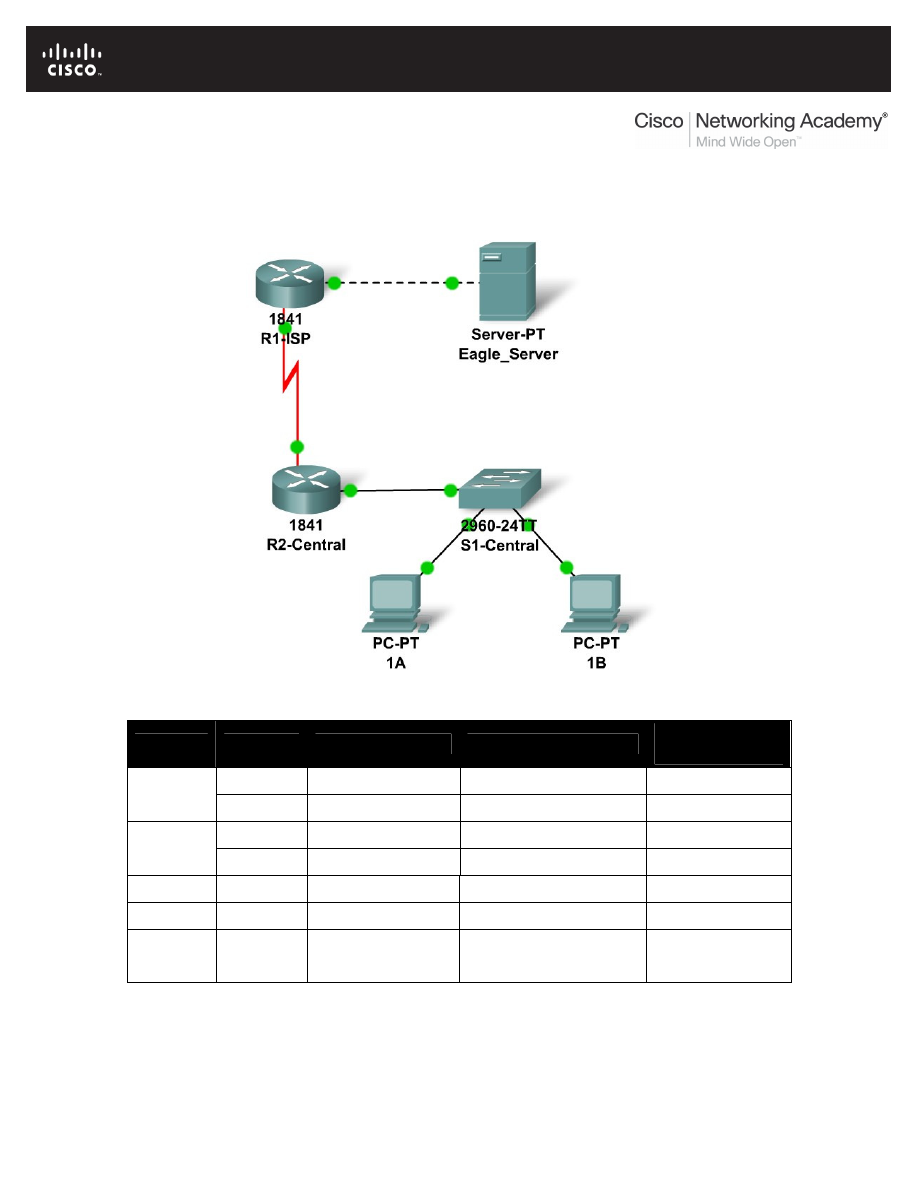
All contents are Copyright © 1992–2007 Cisco Systems, Inc. All rights reserved. This document is Cisco Public Information.
Page 1 of 3
7.6.1: Skills Integration Challenge-Data Link Layer Issues
Topology Diagram
Addressing Table
Device
Interface
IP Address
Subnet Mask
Default
Gateway
Fa0/0
N/A
R1-ISP
S0/0/0
N/A
Fa0/0
R2-
Central
S0/0/0
PC 1A
NIC
PC 1B
NIC
Eagle
Server
NIC

CCNA Exploration
Network Fundamentals:
Data Link Layer
7.6.1: Skills Integration Challenge-Data Link Layer Issues
All contents are Copyright © 1992–2007 Cisco Systems, Inc. All rights reserved. This document is Cisco Public Information.
Page 2 of 3
Learning Objectives
•
IP subnet planning
o
Practice your subnetting skills.
•
Build the network.
o
Connect devices with Ethernet and serial cables.
•
Configure the network.
o
Apply your subnetting scheme to server, PCs, and router interfaces; configure
services and static routing.
•
Test the network
o
Using ping, trace, web traffic, Inspect tool.
Background
Network Interface Cards (NICs) are sometimes thought of as Layer 2 and Layer 1 devices (or as
Layer 2 and Layer 1 components of devices that function at all 7 layers). Sometimes the network
interface card for a serial connection, typically used in WAN connections, is called a WAN
interface card or WIC. In this challenge you must add a WIC to a device to complete the network.
In addition, you have been asked to implement a new IP addressing scheme to the Exploration
lab topology.
Task 1: IP Subnet Planning.
You have been given an IP address block of 172.16.0.0 /22. You must provide for existing
networks as well as future growth.
Subnet assignments are:
•
1st subnet, existing student LAN, up to 400 hosts; (Fa0/0 on R2-Central)
•
2nd subnet, future student LAN, up to 180 hosts; (not yet implemented)
•
3rd subnet, existing ISP LAN, up to 40 hosts; (Fa0/0 on R1-ISP)
•
4th subnet, future ISP LAN, up to 18 hosts; (not yet implemented)
•
5th subnet, existing WAN, point-to-point link; (S0/0/0 on R1-ISP and R2-Central)
•
6th subnet, future WAN, point-to-point link; (not yet implemented)
•
7th subnet, future WAN, point-to-point link. (not yet implemented)
Interface IP addresses:
•
For the server, configure the second highest usable IP address on the ISP LAN subnet.
•
For R1-ISP's Fa0/0 interface, configure the highest usable IP address on the ISP LAN
subnet.
•
For R1-ISP's S0/0/0 interface, configure the highest usable address on the existing WAN
subnet.
•
For R2-Central's S0/0/0 interface, use the lowest usable address on the existing WAN
subnet.
•
For R2-Central's Fa0/0 interface, use the highest usable address on the existing student
LAN subnet.
•
For PCs 1A and 1B, use the first 2 IP addresses (two lowest usable addresses) on the
existing student LAN subnet.
Additional configurations:

CCNA Exploration
Network Fundamentals:
Data Link Layer
7.6.1: Skills Integration Challenge-Data Link Layer Issues
All contents are Copyright © 1992–2007 Cisco Systems, Inc. All rights reserved. This document is Cisco Public Information.
Page 3 of 3
•
For PCs 1A and 1B, in addition to IP configuration, configure them to use DNS services.
•
For the server, enable DNS services, use the domain name eagle-server.example.com,
and enable HTTP services.
Task 2: Finish Building the Network in Packet Tracer, Attending to Some
Layer 2 Issues.
On the R2-Central router, a network interface card is missing for the serial connection to R1-ISP:
add a WIC-2T in the right hand slot. Also, on R2-Central, the Fa0/0 is shutdown; turn it on.
Connect a serial DCE cable to R1-ISP S0/0/0, with the other end to R2-Central S0/0/0. For all
devices, make sure the power is on to all device and interfaces.
Task 3: Configure the Network.
You will need to configure the server, both routers, and the two PCs. You will not need to
configure the switch nor do you need the IOS CLI to configure the routers. Part of the router
configuration has already been done for you: all you must do is configure the static routes and the
interfaces via the GUI. The static route on R1-ISP should point to the existing student LAN subnet
via R2-Central's serial interface IP address; the static route on R2-Central should be a default
static route which points via R1-ISP's serial interface IP address. These procedures were
explained in the Chapter 5 Skills Integration Challenge and practiced in the Chapter 6 Skills
Integration Challenge.
Task 4: Test the Network.
Use ping, trace, web traffic, and the Inspect tool. Trace packet flow in simulation mode, with
HTTP, DNS, TCP, UDP, and ICMP viewable, to test your understanding of how the network is
operating. Note in particular what Layer 2 encapsulation is used in each step of a packet's
journey, and how the headers on the Layer 2 PDUs change.
Reflection
Consider an ICMP echo request packet sent from PC 1A to Eagle Server and the ICMP echo
reply packet that results. What addresses stay the same in this situation, and what addresses
change?
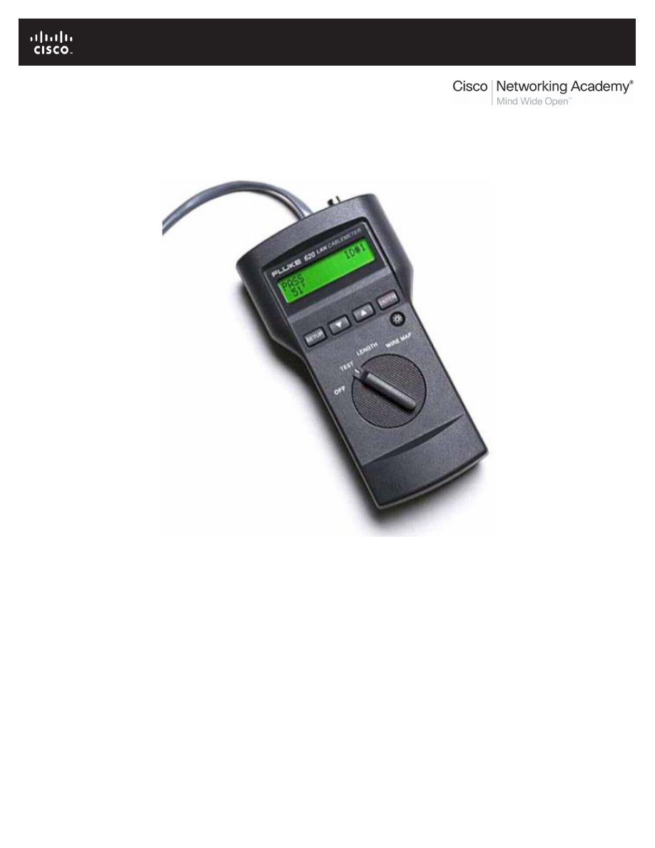
All contents are Copyright © 1992–2007 Cisco Systems, Inc. All rights reserved. This document is Cisco Public Information.
Page 1 of 7
Lab 8.4.1: Media Connectors Lab Activity
Fluke 620 LAN CableMeter
Learning Objectives
Upon completion of this lab, you will be able to:
•
Test cables using a Fluke620 LAN CableMeter and a Fluke LinkRunner
•
Become familiar with the most common functions of a cable tester.
•
Test different cables for type and wiring problems.
Background
Category (CAT 5) unshielded twisted-pair (UTP) cables are wired according to function. End devices,
such as routers and host computers, connect to switches with CAT 5 straight-through cables. When
connected together, however, a CAT 5 crossover cable must be used. This is also true of switches. When
connecting one switch to another, a CAT 5 crossover cable is used again.
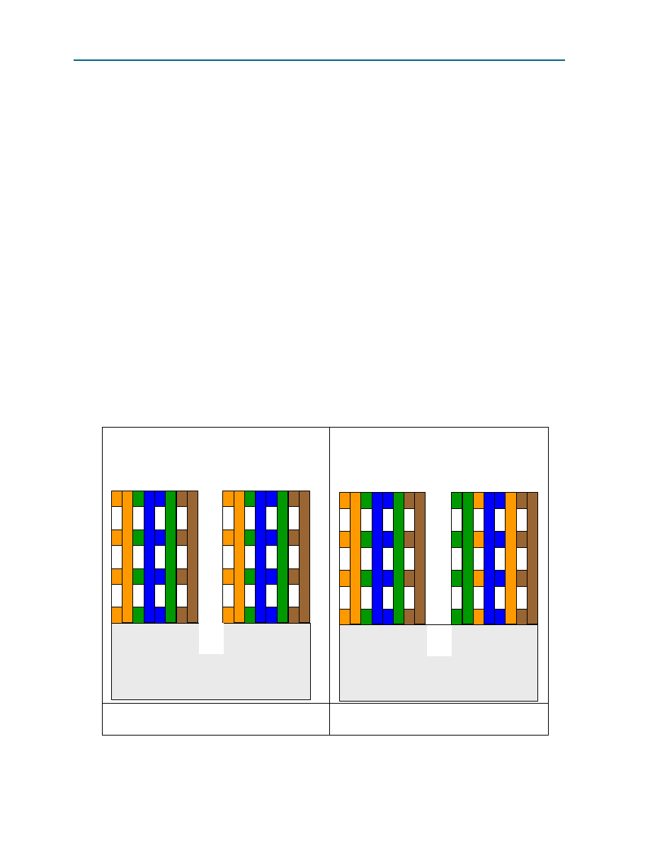
CCNA Exploration
Network Fundamentals: OSI Physical Layer
Lab 8.4.1: Media Connectors Lab Activity
All contents are Copyright © 1992–2007 Cisco Systems, Inc. All rights reserved. This document is Cisco Public Information.
Page 2 of 7
Problems related to cables are one of the most common causes of network failure. Basic cable tests can
be very helpful in troubleshooting cabling problems with UTP. The quality of cabling components used,
the routing and installation of the cable, and quality of the connector terminations will be the main factors
in determining how trouble-free the cabling will be.
The following resources are required:
•
Good CAT 5 straight-through and crossover wired cables of different colors.
•
Category 5 straight-through and crossover wired cables with open wire connections in the middle
or one or more conductors shorted at one end that are different colors and different lengths.
•
Fluke 620 LAN CableMeter or equivalent.
•
Fluke LinkRunner
TIA/EIA 568B is different from TIA/EIA 568A wiring. TIA/EIA 568A straight-through cables can be
identified by the color coding. Similar to Figure 2, below, the right wiring diagram, starting with the green-
white cable, will be identical on both ends.
Scenario
First, you will visually determine whether the CAT 5 cable type is crossover or straight-through. Next, you
will use the cable tester to verify the cable type, as well as common features available with the tester.
Finally, you will use the cable tester to test for bad cables that cannot be determined with a visual
inspection.
Task 1: Become Familiar with the Most Common Functions of a Cable Tester.
TIA/EIA 568B CAT 5 UTP
TIA/EIA 568B CAT 5 UTP
1 2 3 4 5 6 7 8
1 2 3 4 5 6 7 8
1 2 3 4 5 6 7 8
1 2 3 4 5 6 7 8
Straight Through
Straight Through
Crossover
Crossover
TIA/EIA 568B CAT 5 UTP
TIA/EIA 568B CAT 5 UTP
1 2 3 4 5 6 7 8
1 2 3 4 5 6 7 8
1 2 3 4 5 6 7 8
1 2 3 4 5 6 7 8
Figure 1. Straight-through Wire Location
Figure 2. Crossover Wire Location
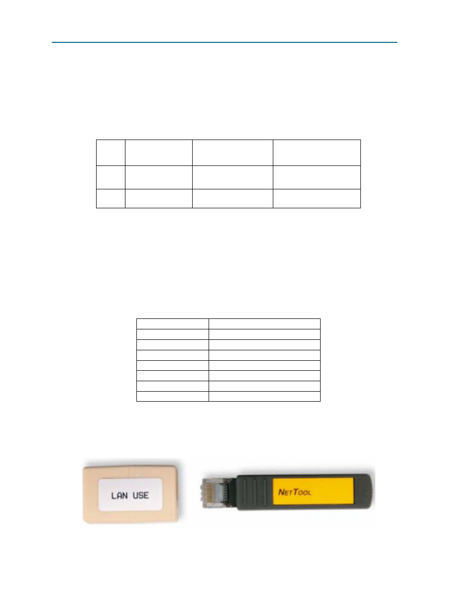
CCNA Exploration
Network Fundamentals: OSI Physical Layer
Lab 8.4.1: Media Connectors Lab Activity
All contents are Copyright © 1992–2007 Cisco Systems, Inc. All rights reserved. This document is Cisco Public Information.
Page 3 of 7
Figures 1 and 2 show the TIA/EIA 568B CAT 5 UTP wire positioning for a straight-through and crossover
cable, respectively. When CAT 5 connectors are held together, wire color is a quick way to determine the
cable type.
Step 1: Visually determine cable types.
There should be two numbered cables available. Perform a visual inspection of the cables and then fill
out the chart below with the cable color, cable type, and use:
Cable
No.
Cable
Color
Cable Type
(straight-through or
crossover)
Cable Use
(Circle correct device)
1
Switch to: host / switch
2
Switch to: host / switch
It is now time to verify the cable type and learn about the common features of the cable tester.
Step 2: Perform initial configuration of the Fluke 620 LAN CableMeter.
Turn the rotary switch selector on the tester to the WIRE MAP position. The wire map function displays
which pins on one end of the cable are connected to which pins on the other end.
Press the SETUP button to enter the setup mode, and observe the LCD screen on the tester. The first
option should be CABLE. Press the UP or DOWN arrow buttons until the desired cable type of UTP is
selected. Press ENTER to accept that setting and go to the next one. Continue pressing the UP/DOWN
arrows and pressing ENTER until the tester is set to the following cabling settings:
Tester Option
Desired Setting – UTP
CABLE:
UTP
WIRING:
10BASE-T or EIA/TIA 4PR
CATEGORY:
CATEGORY 5
WIRE SIZE
AWG 24
CAL to CABLE?
NO
BEEPING:
ON or OFF
LCD CONTRAST
From 1 through 10 (brightest)
When satisfied with the correct settings, press the SETUP button to exit setup mode.
Step 3: Verify cable wire map.
Figure 3. Cable Coupler and Cable Identifier

CCNA Exploration
Network Fundamentals: OSI Physical Layer
Lab 8.4.1: Media Connectors Lab Activity
All contents are Copyright © 1992–2007 Cisco Systems, Inc. All rights reserved. This document is Cisco Public Information.
Page 4 of 7
Use the following procedure to test each cable with the LAN cable coupler and cable identifier, shown in
Figure 3. The coupler and the cable identifier are accessories that come with the Fluke 620 LAN
CableMeter.
Place the near end of the cable into the RJ-45 jack labeled UTP/FTP on the tester. Place the RJ-45-RJ-
45 female coupler on the far end of the cable, and then insert the cable identifier into the other side of the
coupler.
The wiring of both the near and far end of the cable will be displayed. The top set of numbers displayed
on the LCD screen refers to the near end, and the bottom set of numbers refers to the far end.
Perform a Wire Map test on each of the cables provided, and fill in the following table based on the
results. For each cable, write down the number and color, and whether the cable is straight-through or
crossover.
Cable
No.
Cable
Color
Cable
Type (straight-through or crossover)
1
2
Note any problems encountered during this test:
Step 4: Verify cable length.
Move the rotary switch selector on the tester to the LENGTH position. If power was cycled, repeat the
setup steps described in Step 2. The tester LENGTH function displays the length of the cable.
Perform a basic cable test on each of the cables, and complete the following table based on the results.
For each cable, write down the number and color, the cable length, the tester screen test results, and
what the problem is, if there is a problem.
Cable
No.
Cable
Color
Cable
Length
1
2
Note any problems encountered during this test:
Repeat these steps until you are comfortable with the use of the cable tester. In the next task, unknown
cables will be tested.
Task 2: Test Different Cables for Type and Wiring Problems.
Obtain at least 5 different cables from your instructor. Move the rotary switch selector on the tester to the
WIRE MAP position. If power was cycled, repeat the setup steps described in Task 1, Step 2.
Using the cable tester WIRE MAP function, perform a Wire Map test on each of the cables provided. Then
fill in the following table based on the result for each Category 5 cable tested. For each cable, write down
the number and color, whether the cable is straight-through or crossover, the tester screen test results,
and any problem.
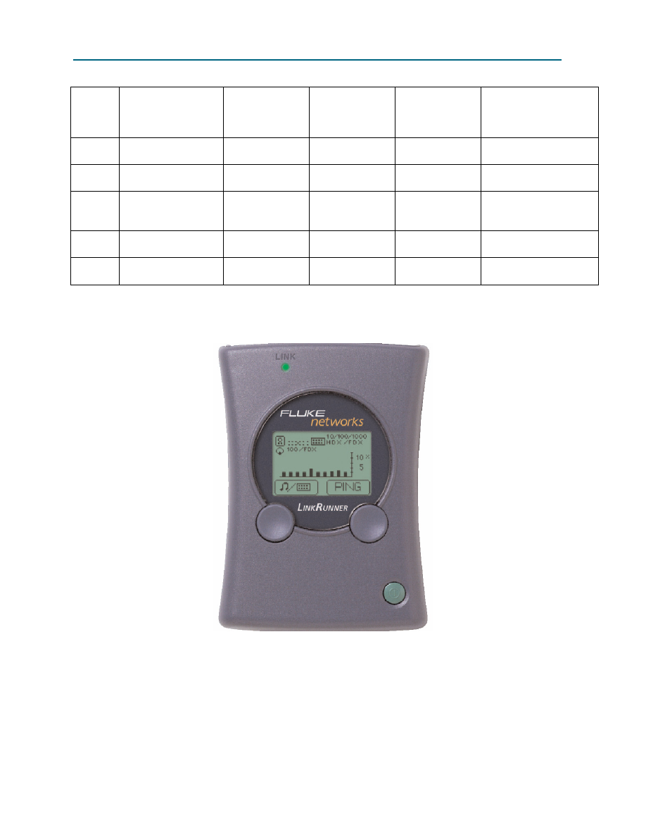
CCNA Exploration
Network Fundamentals: OSI Physical Layer
Lab 8.4.1: Media Connectors Lab Activity
All contents are Copyright © 1992–2007 Cisco Systems, Inc. All rights reserved. This document is Cisco Public Information.
Page 5 of 7
Cable
No.
Cable Type
(Visual inspection)
Cable Color
Cable type
(straight-
through or
crossover)
* Test Results Problem Description
1
2
3
4
5
* Refer to the Fluke manual for detailed description of test results for wire map.
Task 3: Perform initial configuration of the Fluke LinkRunner
Fluke LinkRunner
Step 1: Turn the Fluke LinkRunner on by pressing the green button on the lower right along with the blue
button on the right.
Step 2: Press the green button on the lower right to turn it back off.
Step 3: Place both ends of the cable into the LAN and MAP ports located on top of the LinkRunner and
press the green botton on the lower right along with the blue button to the left.
If it is a correct straight-through cable then two parallel lines (as shown below) will appear on the upper
left corner on the screen.
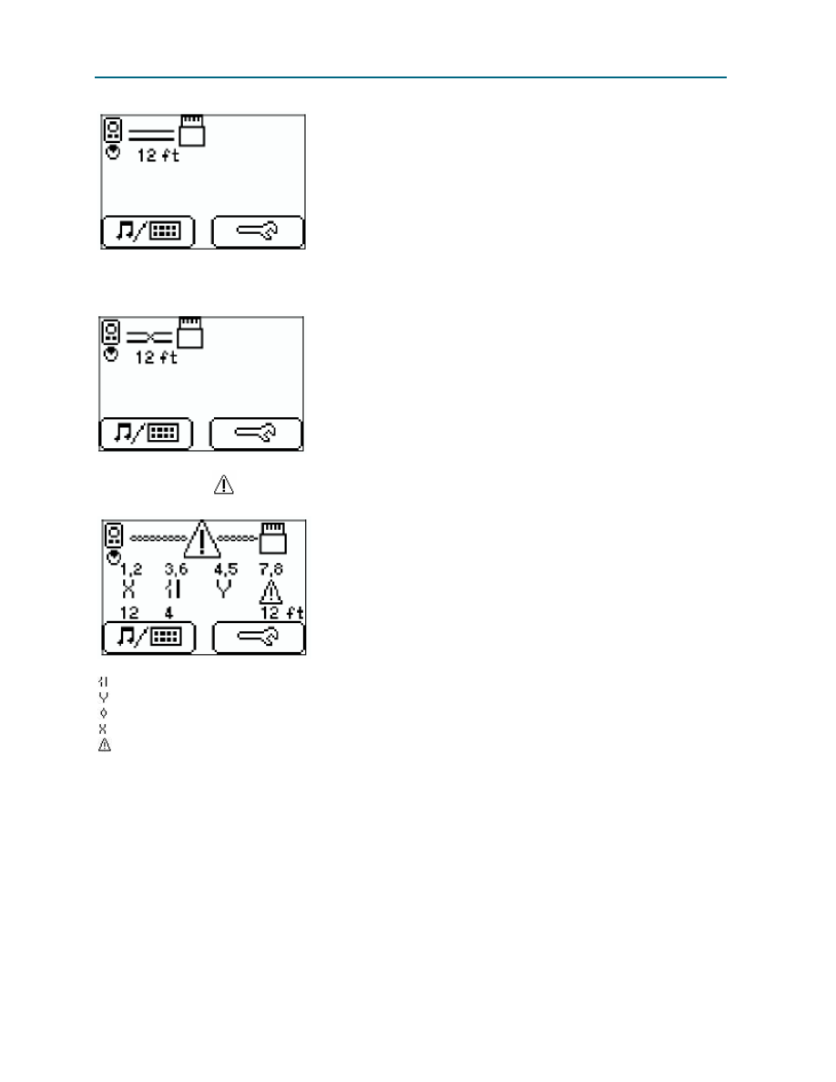
CCNA Exploration
Network Fundamentals: OSI Physical Layer
Lab 8.4.1: Media Connectors Lab Activity
All contents are Copyright © 1992–2007 Cisco Systems, Inc. All rights reserved. This document is Cisco Public Information.
Page 6 of 7
If it is a correct crossover cable then two intersecting lines (as shown below) will appear on the upper left
corner on the screen.
If it is a bad cable,
will appear and details will be displayed below.
Open
Short
Split
Reversal
Unknown
Task 4: Verify Cable Length
Note: The instructions to test a cable are the same as determining cable length.
Step 1: Turn the Fluke LinkRunner on by pressing the green button on the lower right along with the blue
button on the right.
Step 2: Press the green button on the lower right to turn it back off.
Step 3: Place both ends of the cable into the LAN and MAP ports located on top of the LinkRunner and
press the green botton on the lower right along with the blue button to the left.
Step 4: Locate the length of the cable below the icon indicating the type of cable (as shown below).

CCNA Exploration
Network Fundamentals: OSI Physical Layer
Lab 8.4.1: Media Connectors Lab Activity
All contents are Copyright © 1992–2007 Cisco Systems, Inc. All rights reserved. This document is Cisco Public Information.
Page 7 of 7
Task 5: Reflection
Problems related to cables are one of the most common causes of network failure. Network technicians
should be able to determine when to use CAT 5 UTP straight-through and crossover cables.
A cable tester is used to determine cable type, length, and wire map. In a lab environment, cables are
constantly moved and reconnected. A properly functioning cable today may be broken tomorrow. This
isn’t unusual, and is part of the learning process.
Task 6: Challenge
Look for opportunities to test other cables with the Fluke 620 LAN CableMeter. Skills learned in this lab
will enable you to quickly troubleshoot wrong cable types and broken cables.
Task 7: Clean Up
The cable tester is very expensive and should never be left unattended. Return the cable tester to the
instructor when finished.
Ask the instructor where to return used cables. Store the cables neatly for the next class.
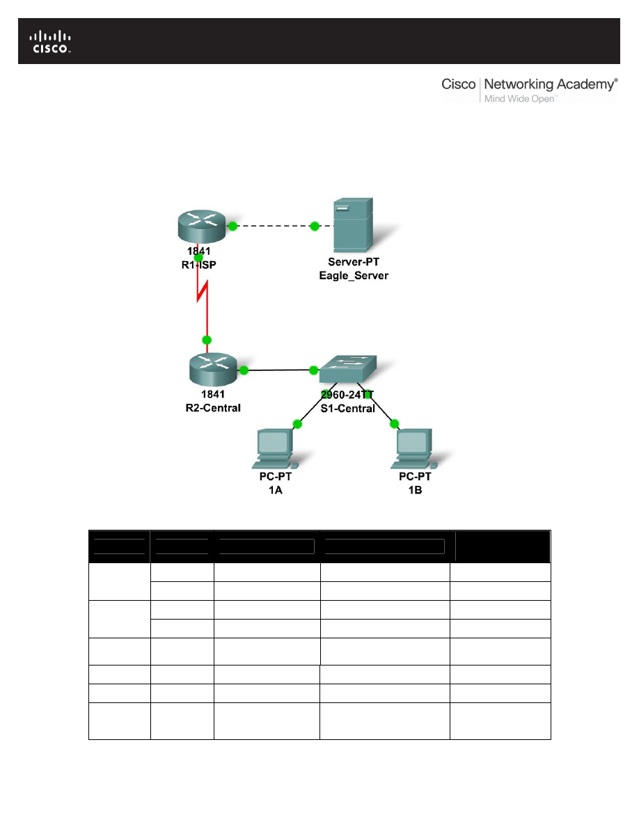
All contents are Copyright © 1992–2007 Cisco Systems, Inc. All rights reserved. This document is Cisco Public Information.
Page 1 of 3
8.5.1: Skills Integration Challenge-Connecting Devices and
Exploring the Physical View
Topology Diagram:
Addressing Table
Device
Interface
IP Address
Subnet Mask
Default
Gateway
Fa0/0
192.168.254.253
255.255.255.0
N/A
R1-ISP
S0/0/0
10.10.10.6
255.255.255.252
N/A
Fa0/0
172.16.255.254
255.255.0.0
10.10.10.6
R2-
Central
S0/0/0
10.10.10.5
255.255.255.252
10.10.10.6
S1-
Central
VLAN 1
172.16.254.1
255.255.0.0
172.16.255.254
PC 1A
NIC
172.16.1.1
255.255.0.0
172.16.255.254
PC 1B
NIC
172.16.1.2
255.255.0.0
172.16.255.254
Eagle
Server
NIC
192.168.254.254
255.255.255.0
192.168.254.253

CCNA Exploration
Network Fundamentals:
OSI Physical Layer
8.5.1: Skills Integration Challenge-Connecting Devices and Exploring the Physical View
All contents are Copyright © 1992–2007 Cisco Systems, Inc. All rights reserved. This document is Cisco Public Information.
Page 2 of 3
Learning Objectives
•
Connect the devices in the standard lab setup
o
Connect the devices
o
Verify connectivity
•
View the standard lab setup in the Physical Workspace
o
Enter and view the Physical Workspace
o
View the standard lab setup at the various levels of the Physical Workspace
Introduction
When working in Packet Tracer, in a lab environment, or in a corporate setting it is important to
know how to select the proper cable and how to properly connect devices. This activity will
examine device configurations in Packet Tracer, select the proper cable based on the
configuration, and connect the devices. This activity will also explore the physical view of the
network in Packet Tracer.
Task 1: Connect the Devices in the Standard Lab Setup.
Step 1: Connect the devices.
Connect PC 1A to the first port on switch S1-Central and PC 1B to the second port on switch S1-
Central using the proper cable.
Click on router R2-Central and examine the configuration using the Config tab. Connect the
proper interface on the router to Interface FastEthernet0/24 on switch S1-Central using the proper
cable.
Click on both routers and examine the configuration using the Config tab. Connect the routers
together using the proper interfaces and the proper cable
Click on router R1-ISP and examine the configuration using the Config tab. Connect the proper
interface on the router to the proper interface on Eagle Server using the proper cable.
Step 2: Verify connectivity.
From the Command Prompt on the Desktop of both PCs issue the command ping
192.168.254.254, the IP address of Eagle Server. If the pings fail, check your connections and
troubleshoot until the pings succeeds. Check your configuration by clicking the Check Results
button.
Task 2: View the Standard Lab Setup in the Physical Workspace.
Step 1: Enter and view the Physical Workspace.
Most of our work in Packet Tracer has been done in the Logical Workspace. In an internetwork,
routers maybe in different sites from across the street to across the globe. The serial link between
the routers represents a dedicated leased line between two locations consisting of a DTE (Data
Terminal Equipment), such as a router, connected to a DCE (Data Communication Equipment),
such as a CSU/DSU or modem. The DCE connects to a service provider's local loop and the
connections are repeated at the other end of the link. The Physical Workspace allows us to see
these relationships more clearly.

CCNA Exploration
Network Fundamentals:
OSI Physical Layer
8.5.1: Skills Integration Challenge-Connecting Devices and Exploring the Physical View
All contents are Copyright © 1992–2007 Cisco Systems, Inc. All rights reserved. This document is Cisco Public Information.
Page 3 of 3
Enter the Physical Workspace by clicking the tab in the upper left hand corner of the Workspace.
It shows the connection between Central City and ISP City.
Step 2: View the standard lab setup at the various levels of the Physical Workspace.
Click on the Central City, it shows the city and the location of the Central Office building. Click on
the Central Office building, it shows the floor plan of the building and the loaction of the Wiring
Closet. Click on the Wiring Closet, it shows a physical representation of the equipment installed in
the wiring closet and the cabling that connects the equipment. Examine this view of the topology.
Click on Intercity on the Navigation bar. Repeat the steps to view the equipment installed in ISP
City.
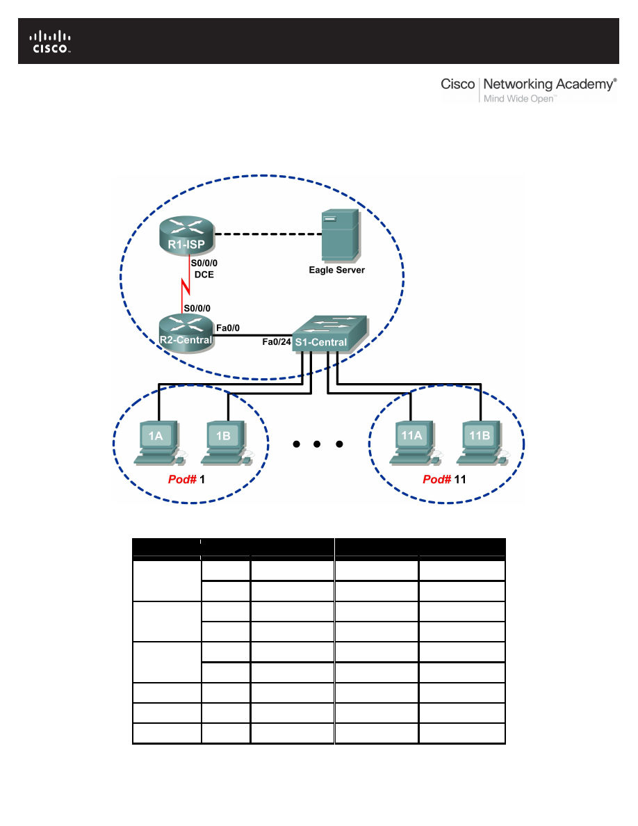
All contents are Copyright © 1992–2007 Cisco Systems, Inc. All rights reserved. This document is Cisco Public Information.
Page 1 of 8
Lab 9.8.1: Address Resolution Protocol (ARP)
Topology Diagram
Addressing Table
Device
Interface IP Address
Subnet Mask
Default Gateway
S0/0/0
10.10.10.6
255.255.255.252 N/A
R1-ISP
Fa0/0
192.168.254.253 255.255.255.0
N/A
S0/0/0
10.10.10.5
255.255.255.252 10.10.10.6
R2-Central
Fa0/0
172.16.255.254 255.255.0.0
N/A
N/A
192.168.254.254 255.255.255.0
192.168.254.253
Eagle Server
N/A
172.31.24.254
255.255.255.0
N/A
hostPod#A
N/A
172.16.Pod#.1
255.255.0.0
172.16.255.254
hostPod#B
N/A
172.16.Pod#.2
255.255.0.0
172.16.255.254
S1-Central
N/A
172.16.254.1
255.255.0.0
172.16.255.254

CCNA Exploration
Network Fundamentals: Ethernet
Lab 9.8.1: Address Resolution Protocol (ARP)
All contents are Copyright © 1992–2007 Cisco Systems, Inc. All rights reserved. This document is Cisco Public Information.
Page 2 of 8
Learning Objectives
Upon completion of this lab, you will be able to:
•
Use Windows arp command.
•
Use Wireshark to examine ARP exchanges.
Background
Address Resolution Protocol (ARP) is used by TCP/IP to map a Layer 3 IP address to a Layer 2 MAC
address. When a frame is placed on the network, it must have a destination MAC address. To
dynamically discover the MAC address to the destination device, an ARP request is broadcast on the
LAN. The device that contains the destination IP address responds, and the MAC address is recorded in
ARP cache. Every device on the LAN keeps its own ARP cache, or small area in RAM that holds ARP
results. An ARP cache timer removes ARP entries that have not been used for a certain period of time.
Depending on the device, times differ. For example, some Windows operating systems store ARP cache
entries for 2 minutes. If the entry is used again during that time, the ARP timer for that entry is extended
to 10 minutes.
ARP is an excellent example in performance tradeoff. With no cache, ARP must continually request
address translations each time a frame is placed on the network. This adds latency to the communication
and could congest the LAN. Conversely, unlimited hold times could cause errors with devices that leave
the network or change the Layer 3 address.
A network engineer needs to be aware of ARP but may not interact with the protocol on a regular basis.
ARP is a protocol that enables network devices to communicate with the TCP/IP protocol. Without ARP,
there is no efficient method to build the datagram Layer 2 destination address. Also, ARP is a potential
security risk. ARP spoofing, or ARP poisoning, is a technique used by an attacker to inject the wrong
MAC address association in a network. An attacker forges the MAC address of a device, and frames are
sent to the wrong destination. Manually configuring static ARP associations is one way to prevent ARP
spoofing. Finally, an authorized MAC address list may be configured Cisco devices to restrict network
access to only approved devices.
Scenario
With a pod host computer, use the Windows arp utility command to examine and change ARP cache
entries.
In Task 2, Wireshark will be used to capture and analyze ARP exchanges between network devices. If
Wireshark has not been loaded on the host pod computer, it can be downloaded from URL
ftp://eagle-server.example.com/pub/eagle_labs/eagle1/chapter9/
, file wireshark-
setup-0.99.4.exe
.

CCNA Exploration
Network Fundamentals: Ethernet
Lab 9.8.1: Address Resolution Protocol (ARP)
All contents are Copyright © 1992–2007 Cisco Systems, Inc. All rights reserved. This document is Cisco Public Information.
Page 3 of 8
Task 1: Use the Windows arp Command.
Step 1: Access the Windows terminal.
C:\> arp
Displays and modifies the IP-to-Physical address translation tables
used by address resolution protocol (ARP).
ARP -s inet_addr eth_addr [if_addr]
ARP -d inet_addr [if_addr]
ARP -a [inet_addr] [-N if_addr]
-a
Displays current ARP entries by interrogating the current
protocol data. If inet_addr is specified, the IP and
Physical addresses for only the specified computer are
displayed. If more than one network interface uses ARP,
entries for each ARP table are displayed.
-g
Same as -a.
inet_addr
Specifies an internet address.
-N if_addr
Displays the ARP entries for the network interface
specified by if_addr.
-d
Deletes the host specified by inet_addr. inet_addr may be
wildcarded with * to delete all hosts.
-s
Adds the host and associates the Internet address inet_addr
with the Physical address eth_addr. The Physical address
is given as 6 hexadecimal bytes separated by hyphens. The
entry is permanent.
eth_addr
Specifies a physical address.
if_addr
If present, this specifies the Internet address of the
interface whose address translation table should be
modified. If not present, the first applicable interface
will be used.
Example:
> arp -s 157.55.85.212 00-aa-00-62-c6-09 .... Adds a static entry.
> arp -a .... Displays the arp table.
C:\>
Figure 1. arp Command Syntax
1. Open a Windows terminal by clicking Start > Run. Type cmd, and click OK.
With no options, the arp command will display useful help information. See Figure 1.
2. Issue the arp command on the pod host computer, and examine the output.
3. Answer the following questions about the arp command:
What command would be used to display all entries in ARP cache?
________________________________________
What command would be used to delete all ARP cache entries (flush ARP cache)?
________________________________________
What command would be used to delete the ARP cache entry for 172.16.255.254?
________________________________________

CCNA Exploration
Network Fundamentals: Ethernet
Lab 9.8.1: Address Resolution Protocol (ARP)
All contents are Copyright © 1992–2007 Cisco Systems, Inc. All rights reserved. This document is Cisco Public Information.
Page 4 of 8
Step 2: Use the arp command to examine local ARP cache.
C:\> arp -a
No ARP Entries Found
C:\>
Figure 2. Empty ARP Cache
Without any network communication, the ARP cache should be empty. This is shown in Figure 2.
Issue the command that displays ARP entries. What are the results?
____________________________________________________________________________________
____________________________________________________________________________________
Step 3: Use the ping command to dynamically add entries in the ARP cache.
The ping command can be used to test network connectivity. By accessing other devices, ARP
associations are dynamically added to ARP cache.
C:\> ping 172.16.1.2
Pinging 172.16.1.2 with 32 bytes of data:
Reply from 172.16.1.2: bytes=32 time<1ms TTL=128
Reply from 172.16.1.2: bytes=32 time<1ms TTL=128
Reply from 172.16.1.2: bytes=32 time<1ms TTL=128
Reply from 172.16.1.2: bytes=32 time<1ms TTL=128
Ping statistics for 172.16.1.2:
Packets: Sent = 4, Received = 4, Lost = 0 (0% loss),
Approximate round trip times in milli-seconds:
Minimum = 0ms, Maximum = 0ms, Average = 0ms
C:\>
Figure 3. ping Command to a Pod Host Computer
1. Use the command ipconfig /all to verify the pod host computer’s Layer 2 and Layer 3
information.
2. Issue the ping command to another pod host computer, shown in Figure 3. Figure 4 shows the
new ARP cache entry.
C:\> arp -a
Interface: 172.16.1.1 --- 0x60004
Internet Address Physical Address Type
172.16.1.2 00-10-a4-7b-01-5f dynamic
C:\>
Figure 4. Display of ARP Cache
How was the ARP entry added to the ARP cache? Hint: review the Type column.
________________________________________
What is the physical address of the destination pod host computer?
________________________________________
.
What is the physical address of the destination pod host computer?
IP Address
Physical Address
How Discovered?

CCNA Exploration
Network Fundamentals: Ethernet
Lab 9.8.1: Address Resolution Protocol (ARP)
All contents are Copyright © 1992–2007 Cisco Systems, Inc. All rights reserved. This document is Cisco Public Information.
Page 5 of 8
3. Do not send any traffic to the computer accessed previously. Wait between 2 and 3 minutes, and
check ARP cache again. Was the ARP cache entry cleared? __________
4. Issue the ping command to the Gateway, R2-Central. Examine ARP cache entry. What is the
physical address of the Gateway? ________________________________________
IP Address
Physical Address
How Discovered?
5. Issue the ping command to Eagle Server, eagle-server.example.com. Examine ARP cache
entry. What is the physical address of Eagle Server? ___________________________________
_____________________________________________________________________________
_____________________________________________________________________________
Step 4: Manually adjust entries in the ARP cache.
To delete entries in ARP cache, issue the command arp –d {inet-addr | *}. Addresses can be
deleted individually by specifying the IP address, or all entries can be deleted with the wildcard *.
Verify that the ARP cache contains two entries: one for the Gateway and one to the destination pod host
computer. It may be easier to ping both devices more than once, which will retain the cache entry for
approximately 10 minutes.
C:\> arp –a
Interface: 172.16.1.1 --- 0x60004
Internet Address Physical Address Type
172.16.1.2 00-10-a4-7b-01-5f dynamic
172.16.255.254 00-0c-85-cf-66-40 dynamic
C:\>
C:\>arp -d 172.16.255.254
C:\> arp -a
Interface: 172.16.1.1 --- 0x60004
Internet Address Physical Address Type
172.16.1.2 00-10-a4-7b-01-5f dynamic
C:\>
Figure 5. Manually Removing an ARP Cache Entry
See Figure 5, which shows how to manually delete an ARP cache entry.
1. On your computer, first verify that the two entries are present. If not, ping the missing entry.
2. Next, delete the entry for the pod host computer.
3. Finally, verify your change.
4. Record the two ARP cache entries:
Device
IP Address
Physical Address
How Discovered?
5. Write the command that will delete the entry for the pod host computer:
________________________________________

CCNA Exploration
Network Fundamentals: Ethernet
Lab 9.8.1: Address Resolution Protocol (ARP)
All contents are Copyright © 1992–2007 Cisco Systems, Inc. All rights reserved. This document is Cisco Public Information.
Page 6 of 8
6. Issue the command on your pod host computer. Record the remaining ARP cache entry:
Device
IP Address
Physical Address
How Discovered?
7. Simulate removing all entries. Write the command that will delete all entries in ARP cache:
________________________________________
8. Issue the command on your pod host computer, and examine the ARP cache with the command
arp -a
. All entries should be removed. ________________________________________
9. Consider a secure environment where the Gateway controls access to a web server that contains
Top Secret information. What is one layer of security that can be applied to ARP cache entries
that could aid in countering ARP spoofing? ________________________________________
10. Write the command that will add a static ARP entry for the Gateway to ARP cache:
________________________________________
11. Examine the ARP cache again, and fill in the following table:
IP Address
Physical Address
Type
For the next task, Wireshark will be used to capture and examine an ARP exchange. Do not close the
Windows terminal—it will be used to view the ARP cache.
Task 2: Use Wireshark to Examine ARP Exchanges .
Step 1: Configure Wireshark for packet captures.
Prepare Wireshark for captures.
1. Click Capture > Options.
2. Select the Interface that corresponds to the LAN.
3. Check the box to Update list of packets in real time.
4. Click Start.
This will begin the packet capture.
Step 2: Prepare the pod host computer for ARP captures.
1. If not already completed, open a Windows terminal window by clicking Start > Run. Type cmd,
and click OK.
2. Flush the ARP cache, which will require ARP to rediscover address maps. Write the command
that you used: ________________________________________
Step 3: Capture and evaluate ARP communication.
In this step, one ping request will be sent to the Gateway, and one ping request will be sent to Eagle
Server. Afterward, Wireshark capture will be stopped and the ARP communication evaluated.
1. Send one ping request to the Gateway, using the command ping –n 1 172.16.255.254.
2. Send one ping request to Eagle Server, using the command ping –n 1 192.168.254.254.
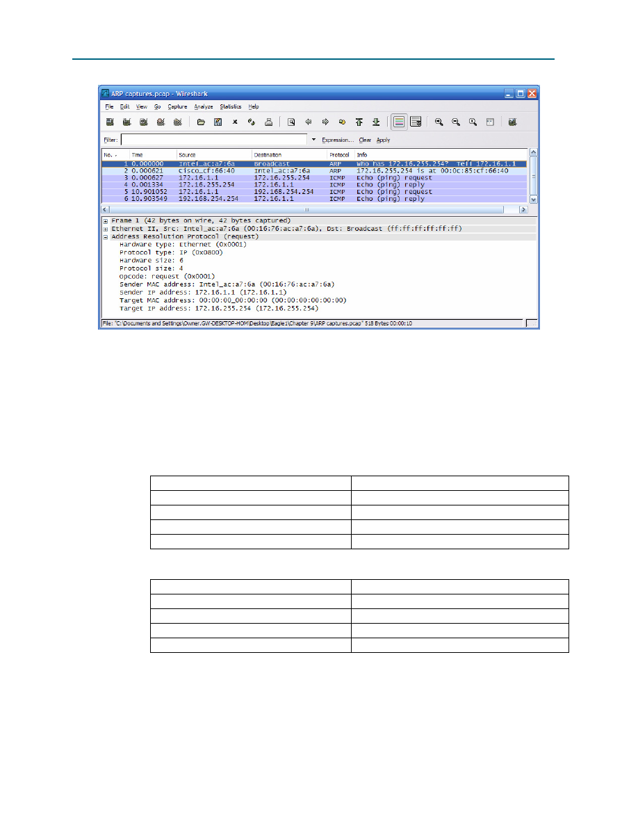
CCNA Exploration
Network Fundamentals: Ethernet
Lab 9.8.1: Address Resolution Protocol (ARP)
All contents are Copyright © 1992–2007 Cisco Systems, Inc. All rights reserved. This document is Cisco Public Information.
Page 7 of 8
Figure 6. Wireshark Capture of ARP Communication
3. Stop Wireshark and evaluate the communication. You should see a Wireshark screen similar to
the screen shown in Figure 6. The Wireshark Packet list window displays the number of packets
captured. The Packet Details Window shows ARP protocol contents.
4. Using your Wireshark capture, answer the following questions:
What was the first ARP packet? ________________________________________
What was the second ARP packet? ________________________________________
Fill in the following table with information about the first ARP packet:
Field
Value
Sender MAC address
Sender IP address
Target MAC address
Target IP address
Fill in the following table with information about the second ARP packet:
Field
Value
Sender MAC address
Sender IP address
Target MAC address
Target IP address
If the Ethernet II frame for an ARP request is a broadcast, why does the Target MAC address
contain all 0s? _________________________________________________________________
Why was there no ARP request for the ping to Eagle Server? ____________________________
_____________________________________________________________________________
_____________________________________________________________________________

CCNA Exploration
Network Fundamentals: Ethernet
Lab 9.8.1: Address Resolution Protocol (ARP)
All contents are Copyright © 1992–2007 Cisco Systems, Inc. All rights reserved. This document is Cisco Public Information.
Page 8 of 8
How long should the Gateway mapping be stored in ARP cache on the pod host computer? Why?
_____________________________________________________________________________
_____________________________________________________________________________
Task 3: Reflection
The ARP protocol maps Layer 3 IP addresses to Layer 2 MAC addresses. If a packet must move across
networks, the Layer 2 MAC address changes with each hop across a router, but the Layer 3 address
never changes.
ARP cache stores ARP address mappings. If the entry was learned dynamically, it will eventually be
deleted from cache. If the entry was manually inserted in ARP cache, it is a static entry and will remain
until the computer is turned off or the ARP cache is manually flushed.
Task 4: Challenge
Using outside resources, perform a search on ARP spoofing. Discuss several techniques used to counter
this type of attack.
Most wireless routers support wireless network access. Using this technique, MAC addresses that are
permitted access to the wireless network are manually added to the wireless router. Using outside
resources, discuss the advantages of configuring wireless network access. Discuss ways that attackers
can circumvent this security.
Task 5: Clean Up
Wireshark was installed on the pod host computer. If Wireshark needs to be uninstalled, click Start >
Control Panel. Open Add or Remove Programs. Highlight Wireshark, and click Remove.
Remove any files created on the pod host computer during the lab.
Unless directed otherwise by the instructor, turn off power to the host computers. Remove anything that
was brought into the lab, and leave the room ready for the next class.
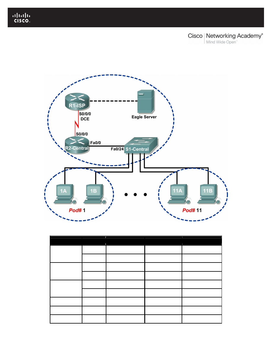
All contents are Copyright © 1992–2007 Cisco Systems, Inc. All rights reserved. This document is Cisco Public Information.
Page 1 of 4
Lab 9.8.2: Cisco Switch MAC Table Examination
Topology Diagram
Addressing Table
Device
Interface
IP Address
Subnet Mask
Default Gateway
S0/0/0
10.10.10.6
255.255.255.252 N/A
R1-ISP
Fa0/0
192.168.254.253 255.255.255.0
N/A
S0/0/0
10.10.10.5
255.255.255.252 10.10.10.6
R2-Central
Fa0/0
172.16.255.254
255.255.0.0
N/A
N/A
192.168.254.254 255.255.255.0
192.168.254.253
Eagle Server
N/A
172.31.24.254
255.255.255.0
N/A
hostPod#A
N/A
172.16.Pod#.1
255.255.0.0
172.16.255.254
hostPod#B
N/A
172.16.Pod#.2
255.255.0.0
172.16.255.254
S1-Central
N/A
172.16.254.1
255.255.0.0
172.16.255.254

CCNA Exploration
Network Fundamentals: Ethernet
Lab 9.8.2: Cisco Switch MAC Table Examination
All contents are Copyright © 1992–2007 Cisco Systems, Inc. All rights reserved. This document is Cisco Public Information.
Page 2 of 4
Learning Objectives
Upon completion of this lab, you will be able to:
•
Use the Telnet protocol to log into a Cisco Switch.
•
Use the Cisco IOS show mac-address-table command to examine MAC address and port
associations.
Background
Switches maintain a table of MAC addresses and associated switch port. When a switch receives a
frame, the destination MAC address is checked against the table, and the corresponding port is used to
route the frame out of the switch. If a switch does not know which port to route the frame, or the frame is
a broadcast, then the frame is routed out all ports except the port where it originated.
Access to Cisco devices can be accomplished through several means. A console port can be used if the
Cisco router or switch is within the same physical proximity of a computer. Using Windows hyperterm
utility, a serial connection can be established. For devices physically distant from the network engineer,
network connectivity can be established through two means. If the network is not secure, a modem
configured on the AUX port enables telephone access. For secure networks, the Cisco device can be
configured for a Telnet session. In this lab, the student will connect to the switch via a Telnet session.
Lab
•
Telnet to S1-Central.
•
Log in with student account.
•
Use show mac-address-table command to examine the mac addresses and association to
ports.
Scenario
Use the Cisco IOS show mac-address-table command to examine the switch MAC address table
and other address-related information.
Telnet is a network service that uses a client-server model. Cisco IOS devices provide a default Telnet
server, and operating systems such as Windows have built-in Telnet clients. Using Telnet, network
engineers can log into network devices from anywhere across a secure network. The Cisco device must
be configured for Telnet access, otherwise it is denied. In Eagle 1, limited privileges have been configured
for student use.
Task 1: Use the Telnet Protocol to Log in to a Cisco Switch.
Step 1: Access the Windows terminal.
Open a Windows terminal by clicking Start > Run. Type cmd, and click OK.
Step 2: Use the Windows Telnet client to access S1-Central.
S1-Central has been configured with 11 student accounts, ccna1 through ccna11. To provide access to
each student, use the userid corresponding to your pod. For example, for host computers on pod 1, use
userid ccna1. Unless directed otherwise by your instructor, the password is cisco.
1. From the Windows terminal, issue the Telnet command, telnet destination-ip-address:
C:/> telnet 172.16.254.1
An access prompt will be displayed, similar to the one shown in Figure 1.

CCNA Exploration
Network Fundamentals: Ethernet
Lab 9.8.2: Cisco Switch MAC Table Examination
All contents are Copyright © 1992–2007 Cisco Systems, Inc. All rights reserved. This document is Cisco Public Information.
Page 3 of 4
*******************************************************************
This is Lab switch S1-Central.
Authorized access only.
*******************************************************************
User Access Verification
Username: ccna1
Password: cisco (*hidden*)
S1-Central#
Figure 1. Telnet Client
2. Enter the applicable user name. When the password prompt appears, type cisco <ENTER>.
The S1-Central# prompt should appear.
Task 2: Use the Cisco IOS show mac-address-table Command to Examine MAC
Addresses and Port Associations.
Step 1: Examine the switch MAC address table.
1. Issue the command show mac-address-table ? <ENTER>. This will output all options for
the command.
2. Use the following table to fill in the command options:
Option
Description
Step 2: Examine dynamic MAC address table entries.
1. Issue the command show mac-address-table.
This command will display static (CPU) and dynamic, or learned, entries.

CCNA Exploration
Network Fundamentals: Ethernet
Lab 9.8.2: Cisco Switch MAC Table Examination
All contents are Copyright © 1992–2007 Cisco Systems, Inc. All rights reserved. This document is Cisco Public Information.
Page 4 of 4
2. List the MAC addresses and corresponding switch ports:
MAC Address
Switch Port
Suppose there was a hub with five active hosts connected to switch port gi0/0. How many MAC
addresses would be listed for switch port gi0/0? __________
Step 3: Examine MAC address table aging time.
1. Issue the command show mac-address-table aging-time.
This command will display the default time, in seconds, that MAC address entries are stored.
2. What is the default aging time for VLAN 1? __________
Task 3: Challenge
What would be the result if the MAC address table was flushed of dynamic entries?
___________________________________________________________________________________
___________________________________________________________________________________
Task 4: Reflection
Using the Telnet protocol, network engineers can access Cisco devices remotely across secure LANs.
This has the benefit of permitting access to remote devices for troubleshooting and monitoring purposes.
A switch contains a MAC address table that lists the MAC address connected to each switch port. When
a frame enters the switch, the switch performs a lookup of the frame destination MAC address. If there is
a match in the MAC address table, the frame is routed out the corresponding port. Without a MAC
address table, the switch would have to flood the frame out each port.
Task 5: Clean Up
Unless directed otherwise by the instructor, turn off power to the host computers. Remove anything that
was brought into the lab, and leave the room ready for the next class.
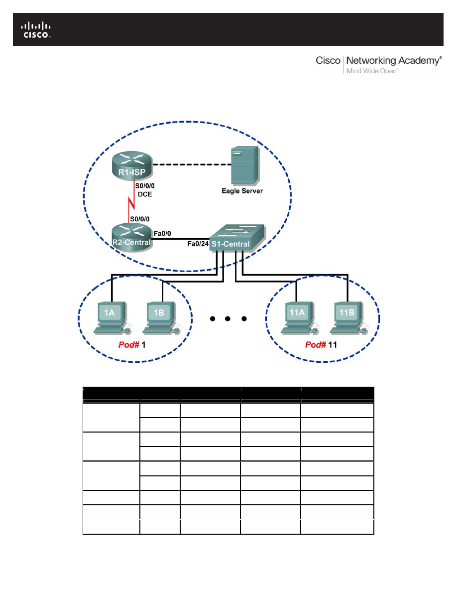
Lab 9.8.3: Intermediary Device as an End Device
Topology Diagram
Addressing Table
Device
Interface
IP Address
Subnet Mask
Default Gateway
S0/0/0 10.10.10.6 255.255.255.252 N/A
R1-ISP
Fa0/0 192.168.254.253 255.255.255.0
N/A
S0/0/0 10.10.10.5 255.255.255.252 10.10.10.6
R2-Central
Fa0/0 172.16.255.254
255.255.0.0 N/A
N/A
192.168.254.254 255.255.255.0 192.168.254.253
Eagle Server
N/A
172.31.24.254 255.255.255.0 N/A
hostPod#A
N/A
172.16.Pod#.1 255.255.0.0
172.16.255.254
hostPod#B
N/A
172.16.Pod#.2 255.255.0.0
172.16.255.254
S1-Central
N/A
172.16.254.1 255.255.0.0 172.16.255.254
All contents are Copyright © 1992–2007 Cisco Systems, Inc. All rights reserved. This document is Cisco Public Information.
Page 1 of 5

CCNA Exploration
Network Fundamentals: Ethernet
Lab 9.8.3: Intermediary Device as an End Device
Learning Objectives
Upon completion of this lab, you will be able to:
• Use Wireshark to capture and analyze frames originating from network nodes.
• Examine the origination of frames in a small network.
Background
A switch is used to route frames between network devices. A switch does not normally originate the frame
to node devices. Rather, a switch efficiently passes the frame from one device to another in the LAN.
Scenario
Wireshark will be used to capture and analyze Ethernet frames. If Wireshark has not been loaded on the
host pod computer, it can be downloaded from URL
server.example.com/pub/eagle_labs/eagle1/chapter9/
, file wireshark-setup-
0.99.4.exe
.
In this lab you will ping a neighbor’s pod host computer.
Write down the IP address and port connection on S1-Central for the neighbor’s pod host computer:
IP Address: ______________________________________ S1-Central port number: ___________
Task 1: Use Wireshark to Capture and Analyze Frames Originating From Network Nodes.
Step 1: Configure Wireshark for packet captures.
Prepare Wireshark for captures.
1. Click
Capture > Options.
2. Select the Interface that corresponds to the LAN.
3. Check the box to Update list of packets in real time.
4. Click
Start.
This will begin the packet capture. During this capture there will probably be more than 200 captures,
making analysis a bit tedious. The critical Telnet conversation between the pod host computer and S1-
Central will be easy to filter.
Step 2: Use the Windows Telnet client to access S1-Central.
S1-Central has been configured with 11 student accounts, ccna1 through ccna11. To provide access to
each student, use the userid corresponding to your pod. For example, for host computers on pod 1, use
userid ccna1. Unless directed otherwise by your instructor, the password is cisco.
1. From the Windows terminal, issue the Telnet command, telnet destination-ip-address:
C:/> telnet 172.16.254.1
2. Enter the appropriate user name and password, cisco.
The S1-Central prompt should be returned, S1-Central#.
All contents are Copyright © 1992–2007 Cisco Systems, Inc. All rights reserved. This document is Cisco Public Information.
Page 2 of 5

CCNA Exploration
Network Fundamentals: Ethernet
Lab 9.8.3: Intermediary Device as an End Device
Step 3: Clear the MAC address table.
1. Examine the switch MAC address table with the command show mac-address-table. In
addition to several static CPU entries, there should be numerous dynamic address table entries.
2. To clear dynamic MAC address table entries, use the clear mac-address-table dynamic
command.
3. List the dynamic MAC address entries:
MAC Address
Switch Port
4. Open a second terminal window. Ping your neighbor’s IP address, which was recorded earlier:
C:>\ ping –n 1 ip-address
5. The MAC address for this computer should be dynamically added in the S1-Central MAC address
table.
6. Again list the dynamic MAC address entries:
MAC Address
Switch Port
What conclusion can be made about how a switch learns MAC addresses connected to switch
interfaces?
____________________________________________________________________________
____________________________________________________________________________
.
7. Close Wireshark capture.
The capture will be analyzed in the next task.
Task 2: Examine the Origination of Frames in a Small Network.
Step 1: Examine a Telnet session to S1-Central.
1. Highlight one of the Telnet session packets. On Wireshark menu, click Analyze | Follow TCP
Stream. A stream content window will open, default display ASCII. If the username and
passwords are not visible, switch to HEX Dump.
2. Verify the username and password that you entered:
Username: ___________________________
Password: __________
3. Close the stream content window.
Step 2: Examine output of the show mac-address-table command.
1. Open Notepad. Captured data will be transferred to Notepad for analysis. There may be
numerous packets that were captured.
2. In the top Wireshark Packet List pane, scroll down to the captured ICMP request. If the bottom
Wireshark Packet Byte window is not visible, click View > Packet bytes.
All contents are Copyright © 1992–2007 Cisco Systems, Inc. All rights reserved. This document is Cisco Public Information.
Page 3 of 5
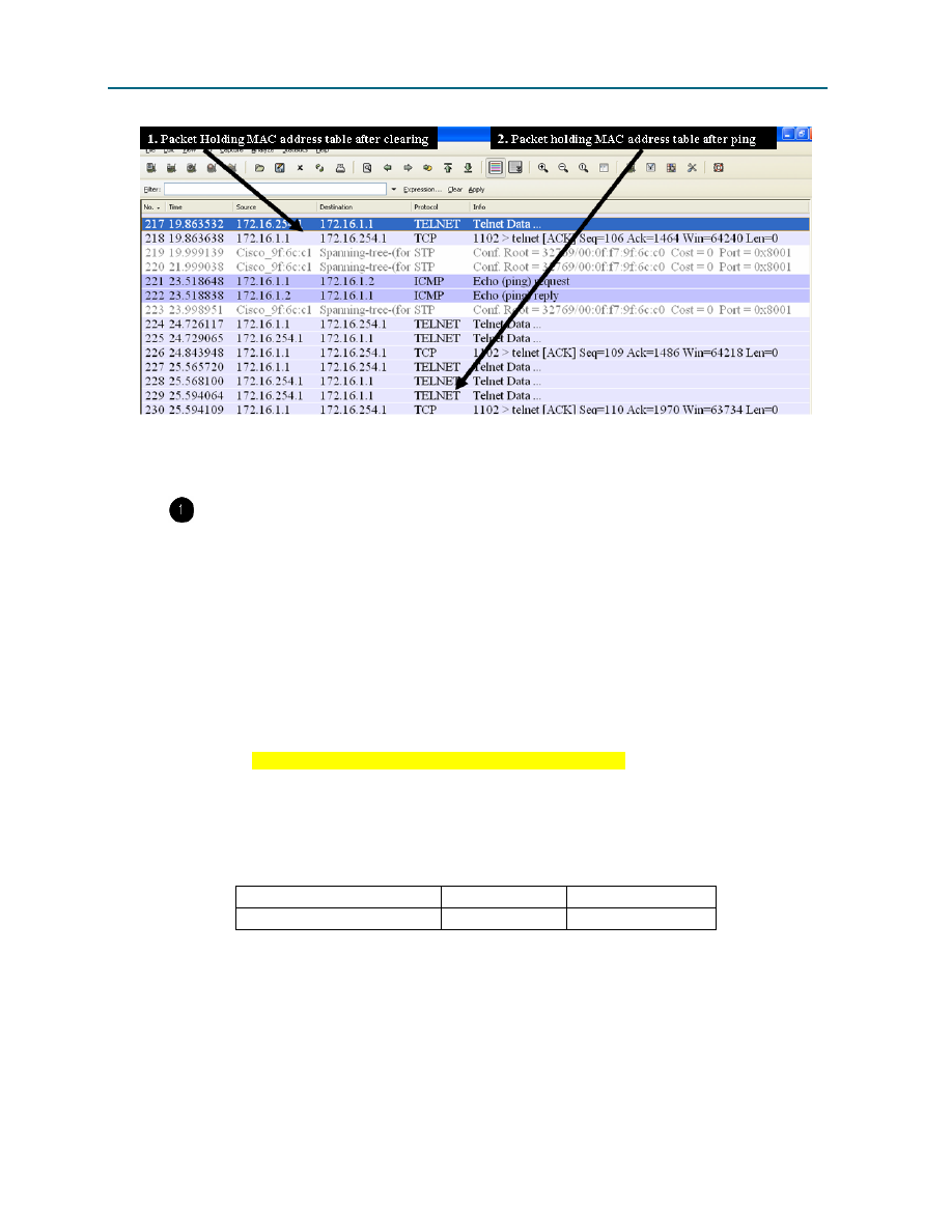
CCNA Exploration
Network Fundamentals: Ethernet
Lab 9.8.3: Intermediary Device as an End Device
Figure 1. Wireshark Capture of Telnet
See Figure 1, a partial output of the Wireshark capture:
Select the last Telnet data packet from S1-Central before the ping command. Next, select
the corresponding Packet byte. Right-click the Packet byte and click Copy > Text only. In
Notepad, click Edit > Paste. Dynamic mappings should be similar to the following output:
{_lEMaNL;RPC Mac Address Table
-------------------------------------------
Vlan Mac Address Type Ports
---- ----------- -------- -----
All 000f.f79f.6cc0 STATIC CPU
All 0100.0ccc.cccc STATIC CPU
All 0100.0ccc.cccd STATIC CPU
All 0100.0cdd.dddd STATIC CPU
1 0010.a47b.015f DYNAMIC Fa0/1
Total Mac Addresses for this criterion: 5
S1-Central#
3. Write down the MAC address and Port number displayed in the output. Does the switch port
correspond to your pod host computer? __________
MAC Address
Type
Port
Why is your pod host computer mapping still in the MAC address table, despite having been
cleared? _____________________________________________________________________
_____________________________________________________________________________
All contents are Copyright © 1992–2007 Cisco Systems, Inc. All rights reserved. This document is Cisco Public Information.
Page 4 of 5

CCNA Exploration
Network Fundamentals: Ethernet
Lab 9.8.3: Intermediary Device as an End Device
Select the last Telnet data packet immediately after the ping reply. Next, select the
corresponding Packet byte. Right-click the Packet byte and click Copy > Text only. In Notepad,
click Edit > Paste. Text should be similar to the following Paste action:
{_lEPaNM;VP Mac Address Table
-------------------------------------------
Vlan Mac Address Type Ports
---- ----------- -------- -----
All 000f.f79f.6cc0 STATIC CPU
All 0100.0ccc.cccc STATIC CPU
All 0100.0ccc.cccd STATIC CPU
All 0100.0cdd.dddd STATIC CPU
1 0010.a47b.015f DYNAMIC Fa0/1
1 0016.76ac.a76a DYNAMIC Fa0/2
Total Mac Addresses for this criterion: 6
S1-Central#
4. Write down the MAC address and Port number for the second dynamic displayed in the output.
Does the switch port correspond to your neighbor’s pod host computer? __________
MAC Address
Type
Port
Task 3: Reflection
The Wireshark capture of a Telnet session between a pod host computer and S1-Central was analyzed to
show how a switch dynamically learns about nodes directly connected to it.
Task 4: Challenge
Use Wireshark to capture and analyze a Telnet session between the pod host computer and the Cisco
switch. Use the Wireshark menu option Analyze > Follow TCP Stream to view the login user ID and
password. How secure is the Telnet protocol? What can be done to make communication with Cisco
devices more secure?
___________________________________________________________________________________
___________________________________________________________________________________
___________________________________________________________________________________
___________________________________________________________________________________
___________________________________________________________________________________
Task 5: Clean Up
Wireshark was installed on the pod host computer. If Wireshark needs to be uninstalled, click Start >
Control Panel. Open Add or Remove Programs. Select Wireshark, and click Remove.
Remove any files created on the pod host computer during the lab.
Unless directed otherwise by the instructor, turn off power to the host computers. Remove anything that
was brought into the lab, and leave the room ready for the next class.
All contents are Copyright © 1992–2007 Cisco Systems, Inc. All rights reserved. This document is Cisco Public Information.
Page 5 of 5
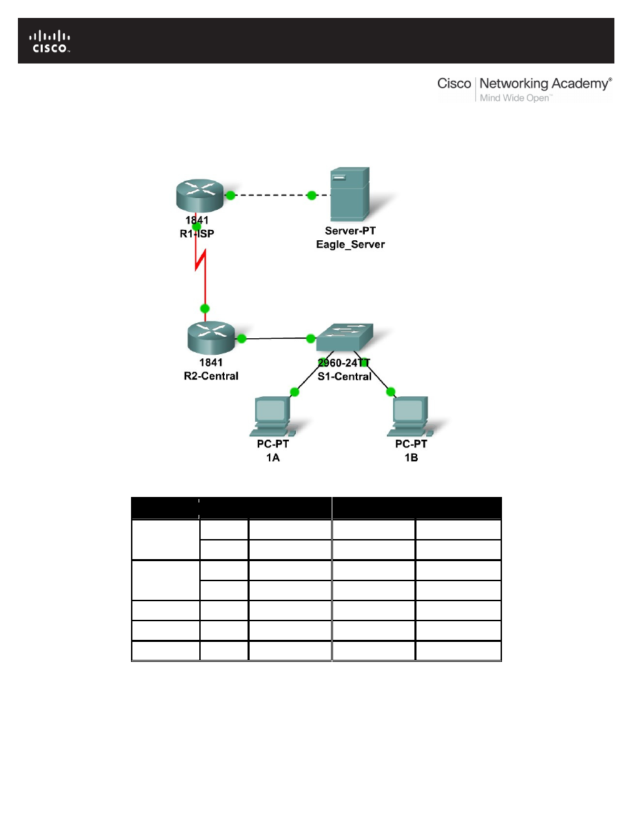
All contents are Copyright © 1992–2007 Cisco Systems, Inc. All rights reserved. This document is Cisco Public Information.
Page 1 of 3
9.9.1: Skills Integration Challenge-Switched Ethernet
Topology Diagram
Addressing Table
Device
Interface IP Address
Subnet Mask
Default Gateway
Fa0/0
192.168.111.134 255.255.255.248 N/A
R1-ISP
S0/0/0 192.168.111.138 255.255.255.252 N/A
Fa0/0
192.168.111.138
R2-Central
S0/0/0 192.168.111.137 255.255.255.252 192.168.111.138
PC 1A
NIC
PC 1B
NIC
Eagle Server
NIC
192.168.111.133 255.255.255.248 192.168.111.134

CCNA Exploration
Network Fundamentals: Ethernet
9.9.1: Skills Integration Challenge-Switched Ethernet
All contents are Copyright © 1992–2007 Cisco Systems, Inc. All rights reserved. This document is Cisco Public Information.
Page 2 of 3
Learning Objectives
Upon completion of this lab, you will be able to:
•
Determine IP subnet planning
•
Repair Ethernet-related network issues.
•
Test the network
Background
You have been asked to repair some problems in the network model related to the Ethernet LAN
connected to R2-Central.
Task 1: IP Subnet Planning.
You have been given an IP address block of 192.168.111.0 /24. You must provide for the three
existing networks.
Subnet assignments are:
•
1st subnet, existing student LAN, up to 100 hosts; (Fa0/0 on R2-Central)
•
2rd subnet, existing ISP LAN, up to 5 hosts; (already configured)
•
3rd subnet, existing WAN, point-to-point link; (already configured)
Interface IP addresses:
•
The server, R1-ISP, and R2-Central's serial interface have already been configured.
•
For R2-Central's Fa0/0 interface, use the highest usable address on the existing student
LAN subnet.
•
For hosts 1A and 1B, use the first 2 IP addresses (two lowest usable addresses) on the
existing student LAN subnet.
•
For Hosts 1A and 1B, the DNS server is 192.168.111.133 /29.
•
The next hop router (to which the default route should point), R1-ISP, has an IP address
of 192.168.111.138 /30
.
Task 2: Repair Problems with the Ethernet Switched LAN.
•
PC 1B has a wireless card and cannot be connected to the switch; add the Fast Ethernet
Interface card PT-HOST-NM-1CFE to PC 1B.
•
Connect this newly installed Fast Ethernet NIC to the Fa0/2 interface on the switch.
•
Connect PC 1A to the Fa0/1 interface on the switch.
•
Connect the Fa0/24 interface on the switch to the R2-Central Fa0/0 interface.
Apparently the Ethernet speed and duplex settings for the R2-Central Fa0/0 interface, the S1-
Central switch interfaces (Fa0/1, Fa0/2, and Fa0/24), and the PC 1A interfaces are incorrect. Set
all Ethernet interfaces to auto negotiate speed and duplex (which will achieve Full Duplex, 100
Mbps operation, if both ends of the link can support it). For all devices, make sure the power is on
to the device and to the interfaces (make sure the Ethernet interfaces are not shut down). Add IP
addresses to the router Fa0/0 interface and to the two PCs-- highest usable subnet address
assigned to the gateway; two lowest usable addresses to the PCs. The static route on the R2-
Central should be a default static route which points via R1-ISP's serial interface IP address.
These procedures were explained in the Chapter 5 and 6 Skills Integration Challenges.

CCNA Exploration
Network Fundamentals: Ethernet
9.9.1: Skills Integration Challenge-Switched Ethernet
All contents are Copyright © 1992–2007 Cisco Systems, Inc. All rights reserved. This document is Cisco Public Information.
Page 3 of 3
Task 3: Test the Network.
Use ping, trace, web traffic, and the Inspect tool to trace packet flow in simulation mode, with
HTTP, DNS, TCP, UDP, ICMP, and ARP viewable, to test your understanding of how the network
is operating.
Reflection
The two Layer 2 (and Layer 1 technologies) in this model are a serial connection (between the
routers) and the Ethernet LANs (for the ISP server and with S1-Central switch). Compare and
contrast the serial connection with Ethernet. In a future course you will learn much more about
switched Ethernet technologies.
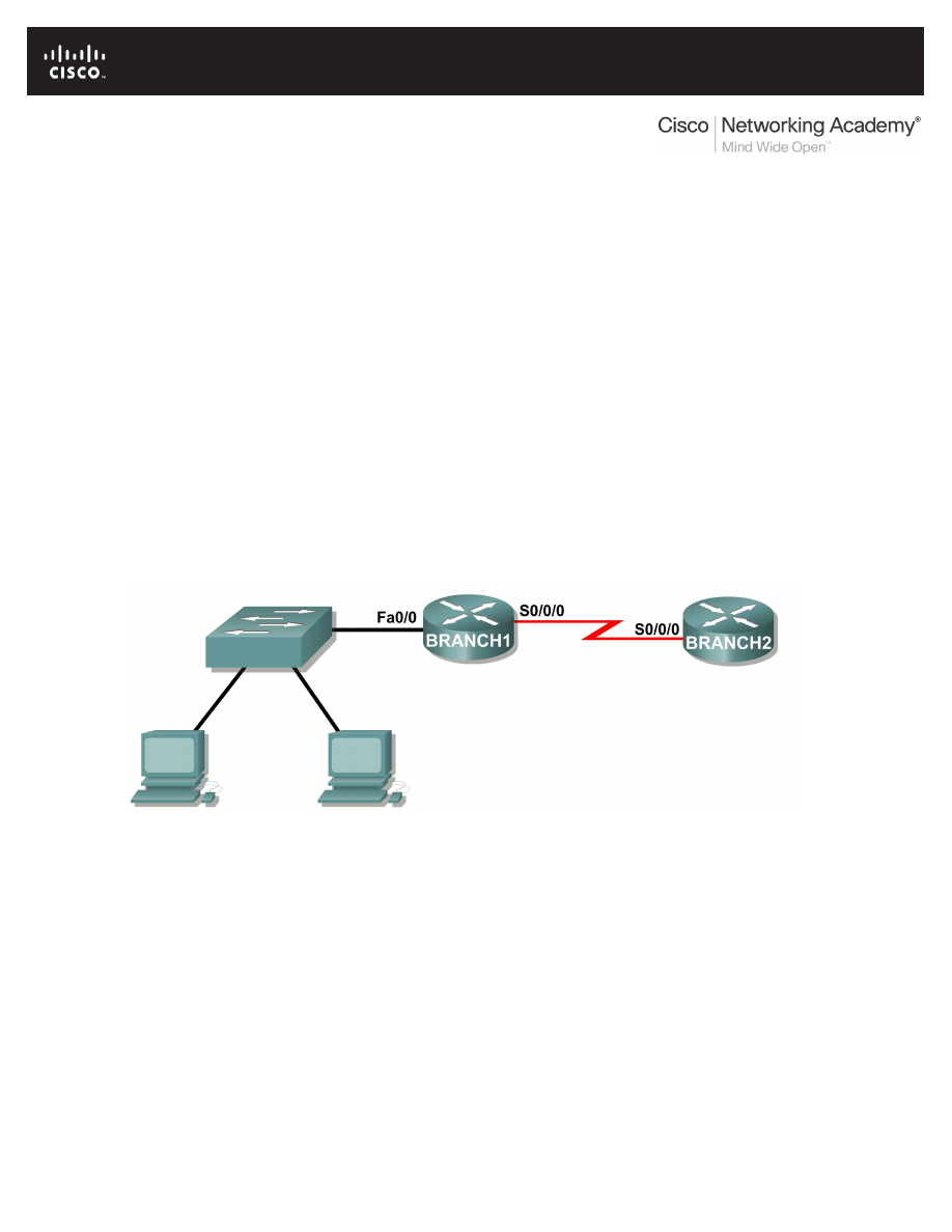
All contents are Copyright © 1992–2007 Cisco Systems, Inc. All rights reserved. This document is Cisco Public Information.
Page 1 of 6
Lab 10.3.2: How Many Networks?
Learning Objectives
Upon completion of this lab, you will be able to:
•
Determine the number of subnets.
•
Design an appropriate addressing scheme.
•
Assign addresses and subnet mask pairs to device interfaces.
•
Examine the use of the available network address space.
Scenario
In this lab, you have been given the network address 192.168.26.0/24 to subnet and provide the
IP addressing for the networks shown in the Topology Diagrams. You must determine the number
of networks needed then design an appropriate addressing scheme. Place the correct address
and mask in the Addressing Table. In this example, the number of hosts is not important. You are
only required to determine the number of subnets per topology example.
Topology Diagram A
Task 1: Determine the Number of Subnets in the Topology Diagram.
Step 1: How many networks are there? ____
Step 2: How many bits should you borrow to create the required number of subnets? ____
Step 3: How many usable host addresses and usable subnets did this give you? ____
Step 4: What is the new subnet mask in decimal form? _____________________________
Step 5: How many subnets are available for future use? ____
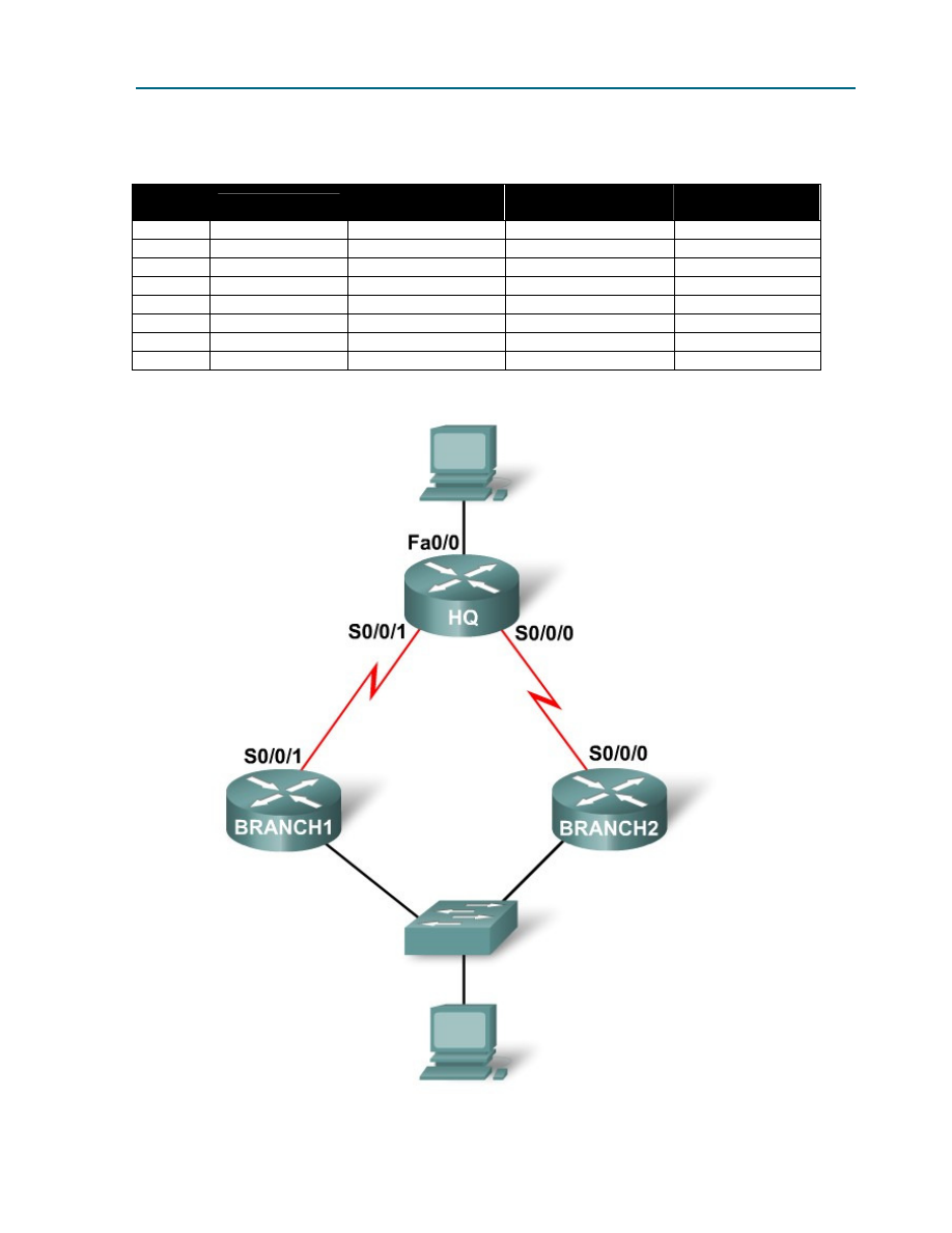
CCNA Exploration
Network Fundamentals: Planning and Cabling Networks
Lab 10.3.2 How Many Networks?
All contents are Copyright © 1992–2007 Cisco Systems, Inc. All rights reserved. This document is Cisco Public Information.
Page 2 of 6
Task 2: Record Subnet Information.
Step 1: Fill in the following chart with the subnet information.
Subnet
Number
Subnet Address
First Usable
Host Address
Last Usable
Host Address
Broadcast
Address
0
1
2
3
4
5
6
7
Topology Diagram B
Fa0/0
Fa0/0
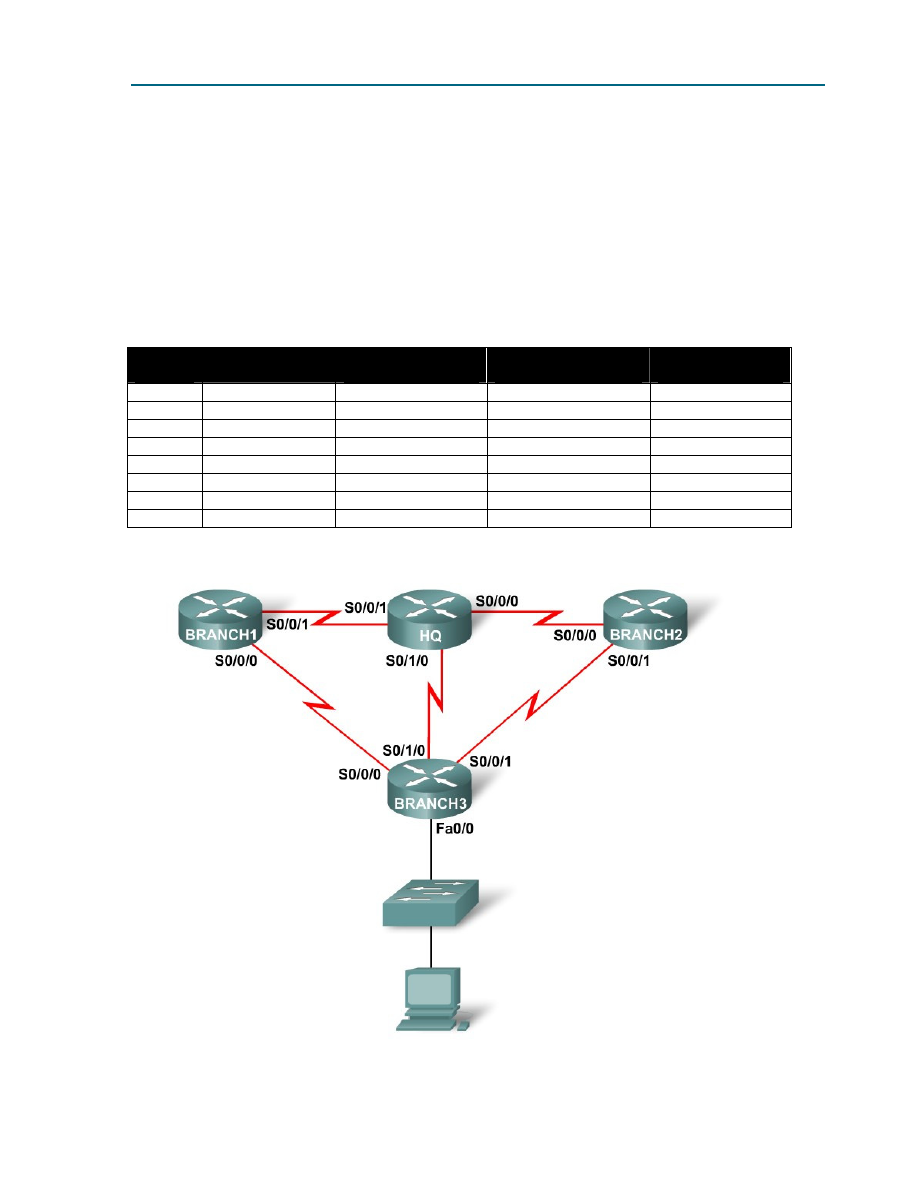
CCNA Exploration
Network Fundamentals: Planning and Cabling Networks
Lab 10.3.2 How Many Networks?
All contents are Copyright © 1992–2007 Cisco Systems, Inc. All rights reserved. This document is Cisco Public Information.
Page 3 of 6
Task 1: Determine the Number of Subnets in the Topology Diagram.
Step 1: How many networks are there? ____
Step 2: How many bits should you borrow to create the required number of subnets? ____
Step 3: How many usable host addresses and usable subnets did this give you? ____
Step 4: What is the new subnet mask in decimal form? _____________________________
Step 5: How many subnets are available for future use? ____
Task 2: Record Subnet Information.
Step 1: Fill in the following chart with the subnet information.
Subnet
Number
Subnet Address
First Usable
Host Address
Last Usable
Host Address
Broadcast
Address
0
1
2
3
4
5
6
7
Topology Diagram C

CCNA Exploration
Network Fundamentals: Planning and Cabling Networks
Lab 10.3.2 How Many Networks?
All contents are Copyright © 1992–2007 Cisco Systems, Inc. All rights reserved. This document is Cisco Public Information.
Page 4 of 6
Task 1: Determine the Number of Subnets in the Topology Diagram.
Step 1: How many networks are there? ____
Step 2: How many bits should you borrow to create the required number of subnets? ____
Step 3: How many usable host addresses and usable subnets did this give you? ____
Step 4: What is the new subnet mask in decimal form? _____________________________
Step 5: How many subnets are available for future use? ____
Task 2: Record Subnet Information.
Step 1: Fill in the following chart with the subnet information.
Subnet
Number
Subnet Address
First Usable
Host Address
Last Usable
Host Address
Broadcast
Address
0
1
2
3
4
5
6
7
8
9
10
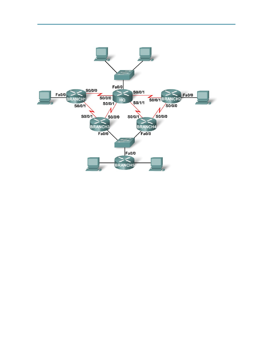
CCNA Exploration
Network Fundamentals: Planning and Cabling Networks
Lab 10.3.2 How Many Networks?
All contents are Copyright © 1992–2007 Cisco Systems, Inc. All rights reserved. This document is Cisco Public Information.
Page 5 of 6
Topology Diagram D
Task 1: Determine the Number of Subnets in the Topology Diagram.
Step 1: How many networks are there? ____
Step 2: How many bits should you borrow to create the required number of subnets? ____
Step 3: How many usable host addresses and usable subnets did this give you? ____
Step 4: What is the new subnet mask in decimal form? _____________________________
Step 5: How many subnets are available for future use? ____
Fa1/0

CCNA Exploration
Network Fundamentals: Planning and Cabling Networks
Lab 10.3.2 How Many Networks?
All contents are Copyright © 1992–2007 Cisco Systems, Inc. All rights reserved. This document is Cisco Public Information.
Page 6 of 6
Task 2: Record Subnet Information.
Step 1: Fill in the following chart with the subnet information.
Subnet
Number
Subnet Address
First Usable
Host Address
Last Usable
Host Address
Broadcast
Address
0
1
2
3
4
5
6
7
8
9
10
11
12
13
14
15
16
Reflection
What information is needed when determining an appropriate addressing scheme for a network?
_____________________________________________________________________________
_____________________________________________________________________________
_____________________________________________________________________________
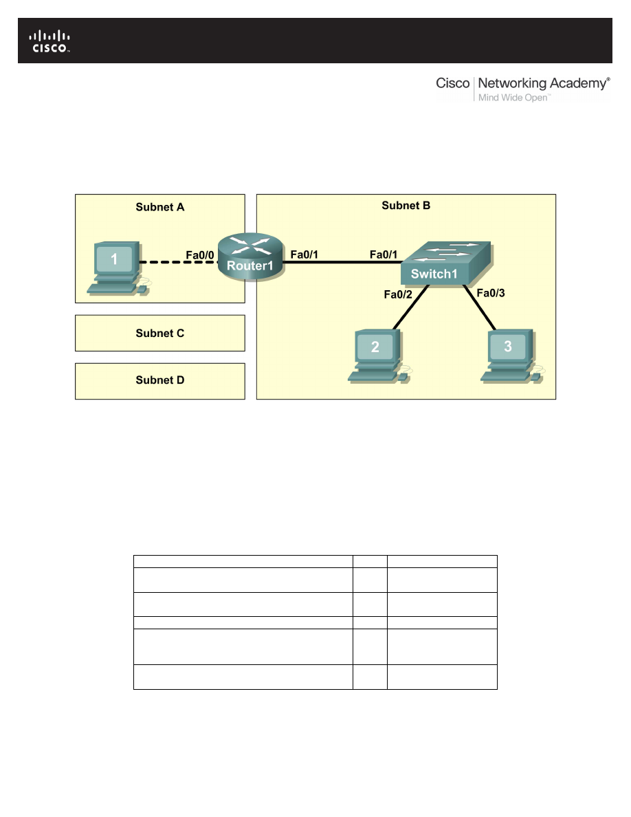
CCNA Exploration
Network Fundamentals: Planning and Cabling Networks
Lab 10.6.1 Creating a Small Lab Topology
All contents are Copyright © 1992–2007 Cisco Systems, Inc. All rights reserved. This document is Cisco Public Information.
Page 1 of 8
Lab 10.6.1: Creating a Small Lab Topology
Topology Diagram
Learning Objectives
Upon completion of this lab, you will be able to:
•
Design the logical network.
•
Configure the physical lab topology.
•
Configure the logical LAN topology.
•
Verify LAN connectivity.
Background
Hardware
Qty
Description
Cisco Router
1
Part of CCNA Lab
bundle
Cisco Switch
1
Part of CCNA Lab
bundle
*Computer (host)
3
Lab computer
Cat-5 or better straight-through UTP cables
3
Connects Router1
and computers Host1
and Host2 to Switch1
Cat-5 crossover UTP cable
1
Connects computer
Host1 to Router1
Table 1. Equipment and Hardware for Lab
Gather the necessary equipment and cables. To configure the lab, refer to the equipment and hardware
listed in Table 1.

CCNA Exploration
Network Fundamentals: Planning and Cabling Networks
Lab 10.6.1 Creating a Small Lab Topology
All contents are Copyright © 1992–2007 Cisco Systems, Inc. All rights reserved. This document is Cisco Public Information.
Page 2 of 8
Scenario
In this lab you will create a small network that requires connecting network devices and configuring host
computers for basic network connectivity. SubnetA and SubnetB are subnets that are currently needed.
SubnetC and SubnetD are anticipated subnets, not yet connected to the network. The 0
th
subnet will be
used.
Note: Appendix 1 contains a subnet chart for the last IP address octet.
Task 1: Design the Logical Network.
Given an IP address and mask of 172.20.0.0 / 24 (address / mask), design an IP addressing
scheme that satisfies the following requirements:
Subnet
Number of Hosts
SubnetA
2 maximum
SubnetB
6 maximum
SubnetC
47 maximum
SubnetD
125 maximum
Host computers from each subnet will use the first available IP address in the address block. Router
interfaces will use the last available IP address in the address block.
Step 1: Design SubnetD address block.
Begin the logical network design by satisfying the requirement of SubnetD, which requires the largest
block of IP addresses. Refer to the subnet chart, and pick the first address block that will support
SubnetD.
Fill in the following table with IP address information for SubnetD:
Network
Address
Mask
First Host
Address
Last Host
Address
Broadcast
What is the bit mask? __________________________________________________
Step 2: Design SubnetC address block.
Satisfy the requirement of SubnetC, the next largest IP address block. Refer to the subnet chart, and pick
the next available address block that will support SubnetC.
Fill in the following table with IP address information for SubnetC:
Network
Address
Mask
First Host
Address
Last Host
Address
Broadcast
What is the bit mask? __________________________________________________
Step 3: Design SubnetB address block.
Satisfy the requirement of SubnetB, the next largest IP address block. Refer to the subnet chart, and pick
the next available address block that will support SubnetB.
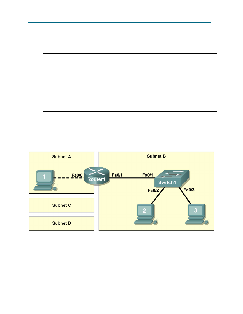
CCNA Exploration
Network Fundamentals: Planning and Cabling Networks
Lab 10.6.1 Creating a Small Lab Topology
All contents are Copyright © 1992–2007 Cisco Systems, Inc. All rights reserved. This document is Cisco Public Information.
Page 3 of 8
Fill in the following table with IP address information for SubnetB:
Network
Address
Mask
First Host
Address
Last Host
Address
Broadcast
What is the bit mask? ________________________________________________________
Step 4: Design SubnetA address block.
Satisfy the requirement of SubnetA. Refer to the subnet chart, and pick the next available address block
that will support SubnetA.
Fill in the following table with IP address information for SubnetA:
Network
Address
Mask
First Host
Address
Last Host
Address
Broadcast
What is the bit mask? ________________________________________________________
Task 2: Configure the Physical Lab Topology.
Step 1: Physically connect devices.
Figure 1. Cabling the Network
Cable the network devices as shown in Figure 1.
What cable type is needed to connect Host1 to Router1, and why? _____________________________
__________________________________________________________________________________
What cable type is needed to connect Host1, Host2, and Router1 to Switch1, and why? ____________
__________________________________________________________________________________
__________________________________________________________________________________
If not already enabled, turn power on to all devices.

CCNA Exploration
Network Fundamentals: Planning and Cabling Networks
Lab 10.6.1 Creating a Small Lab Topology
All contents are Copyright © 1992–2007 Cisco Systems, Inc. All rights reserved. This document is Cisco Public Information.
Page 4 of 8
Step 2: Visually inspect network connections
After cabling the network devices, take a moment to verify the connections. Attention to detail now will
minimize the time required to troubleshoot network connectivity issues later. Ensure that all switch
connections show green. Any switch connection that does not transition from amber to green should be
investigated. Is the power applied to the connected device? Is the correct cable used? Is the correct cable
good?
What type of cable connects Router1 interface Fa0/0 to Host1? ________________________________
What type of cable connects Router1 interface Fa0/1 to Switch1? ______________________________
What type of cable connects Host2 to Switch1? _____________________________________________
What type of cable connects Host3 to Switch1? _____________________________________________
Is all equipment turned on? __________
Task 3: Configure the Logical Topology.
Step 1: Document logical network settings.
The host computer Gateway IP address is used to send IP packets to other networks. Therefore, the
Gateway address is the IP address assigned to the router interface for that subnet.
From the IP address information recorded in Task 1, write down the IP address information for each
computer:
Host1
IP Address
IP Mask
Gateway Address
Host2
IP Address
IP Mask
Gateway Address
Host3
IP Address
IP Mask
Gateway Address
Step 2: Configure Host1 computer.
On Host1, click Start > Control Panel > Network Connections. Right-click the Local Area Connection
device icon and choose Properties.
On the General tab, select Internet Protocol (TCP/IP), and then click the Properties button.
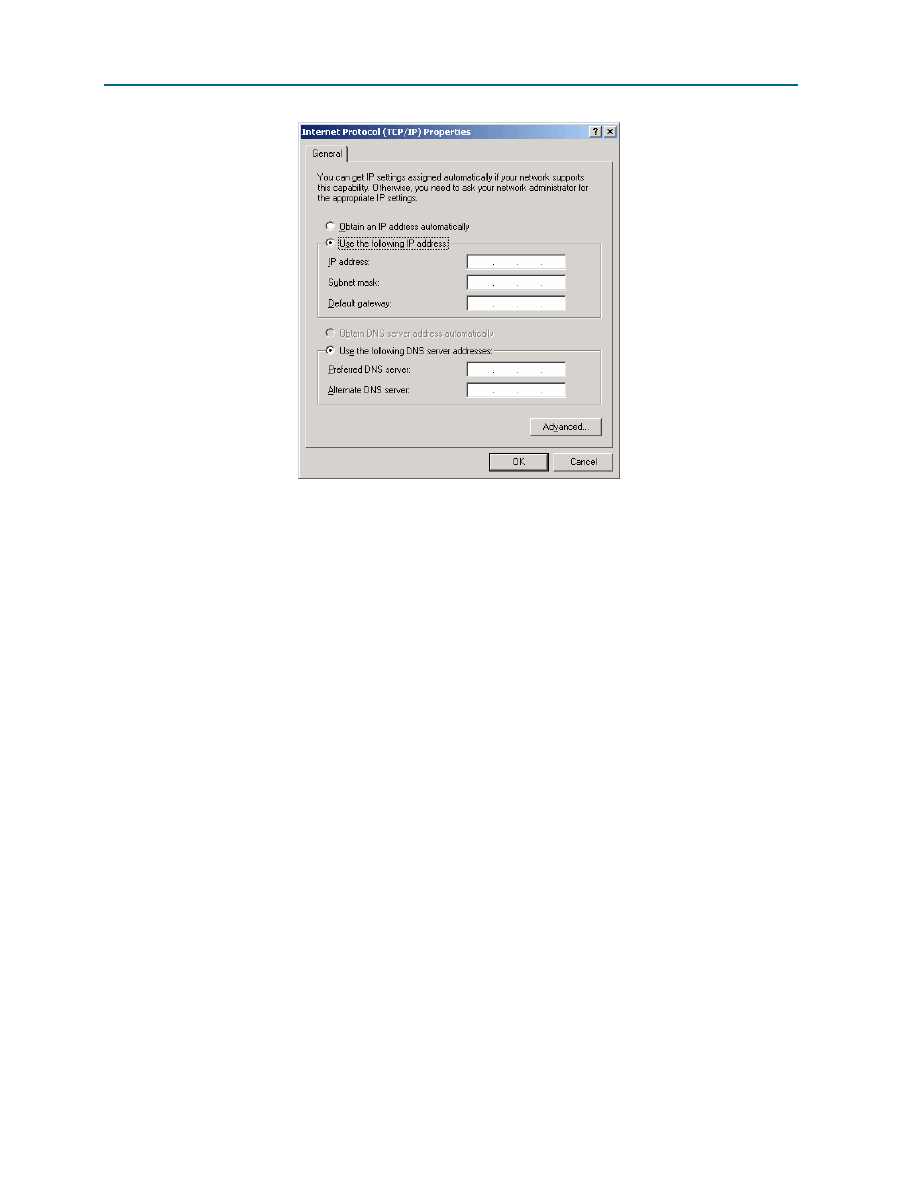
CCNA Exploration
Network Fundamentals: Planning and Cabling Networks
Lab 10.6.1 Creating a Small Lab Topology
All contents are Copyright © 1992–2007 Cisco Systems, Inc. All rights reserved. This document is Cisco Public Information.
Page 5 of 8
Figure 2. Host1 IP Address and Gateway Settings
Refer to Figure 2 for Host1 IP address and gateway settings. Manually enter the following information,
recorded in Step 1, above:
IP address: Host1 IP address
Subnet mask: Host1 subnet mask
Default gateway: Gateway IP address
When finished, close the Internet Protocols (TCP/IP) Properties window by clicking OK. Close the Local
Area Connection window. Depending on the Windows operating system, the computer may require a
reboot for changes to be effective.
Step 3: Configure Host2 and Host3 computers.
Repeat Step 2 for computers Host2 and Host3, using the IP address information for those computers.
Task 4: Verify Network Connectivity.
Verify with your instructor that Router1 has been configured. Otherwise, connectivity will be broken
between LANs. Switch1 should have a default configuration.
Network connectivity can be verified with the Windows ping command. Open a windows terminal by
clicking Start > Run. Type cmd, and press Enter.

CCNA Exploration
Network Fundamentals: Planning and Cabling Networks
Lab 10.6.1 Creating a Small Lab Topology
All contents are Copyright © 1992–2007 Cisco Systems, Inc. All rights reserved. This document is Cisco Public Information.
Page 6 of 8
Use the following table to methodically verify and record connectivity with each network device. Take
corrective action to establish connectivity if a test fails:
From
To
IP Address
Ping Results
Host1
Gateway (Router1, Fa0/0)
Host1
Router1, Fa0/1
Host1
Host2
Host1
Host3
Host2
Host3
Host2
Gateway (Router1, Fa0/1)
Host2
Router1, Fa0/0
Host2
Host1
Host3
Host2
Host3
Gateway (Router1, Fa0/1)
Host3
Router1, Fa0/0
Host3
Host1
Note any break in connectivity. When troubleshooting connectivity issues, the topology diagram can be
extremely helpful.
In the above scenario, how can a malfunctioning Gateway be detected?
___________________________________________________________________________________
___________________________________________________________________________________
Task 5: Reflection
Review any physical or logical configuration problems encountered during this lab. Be sure that you have
a thorough understanding of the procedures used to verify network connectivity.
This is a particularly important lab. In addition to practicing IP subnetting, you configured host computers
with network addresses and tested them for connectivity.
It is best to practice host computer configuration and verification several times. This will reinforce the skills
you learned in this lab and make you a better network technician.
Task 6: Challenge
Ask your instructor or another student to introduce one or two problems in your network when you aren’t
looking or are out of the lab room. Problems can be either physical (wrong UTP cable) or logical (wrong
IP address or gateway). To fix the problems:
1. Perform a good visual inspection. Look for green link lights on Switch1.

CCNA Exploration
Network Fundamentals: Planning and Cabling Networks
Lab 10.6.1 Creating a Small Lab Topology
All contents are Copyright © 1992–2007 Cisco Systems, Inc. All rights reserved. This document is Cisco Public Information.
Page 7 of 8
2. Use the table provided in Task 3 to identify failed connectivity. List the problems:
_____________________________________________________________________________
_____________________________________________________________________________
_____________________________________________________________________________
_____________________________________________________________________________
_____________________________________________________________________________
3. Write down your proposed solution(s):
_____________________________________________________________________________
_____________________________________________________________________________
_____________________________________________________________________________
_____________________________________________________________________________
_____________________________________________________________________________
4. Test your solution. If the solution fixed the problem, document the solution. If the solution did not
fix the problem, continue troubleshooting.
_____________________________________________________________________________
_____________________________________________________________________________
_____________________________________________________________________________
_____________________________________________________________________________
_____________________________________________________________________________
_____________________________________________________________________________
_____________________________________________________________________________
_____________________________________________________________________________
Task 7: Clean Up
Unless directed otherwise by the instructor, restore host computer network connectivity, and then turn off
power to the host computers.
Carefully remove cables and return them neatly to their storage. Reconnect cables that were
disconnected for this lab.
Remove anything that was brought into the lab, and leave the room ready for the next class.
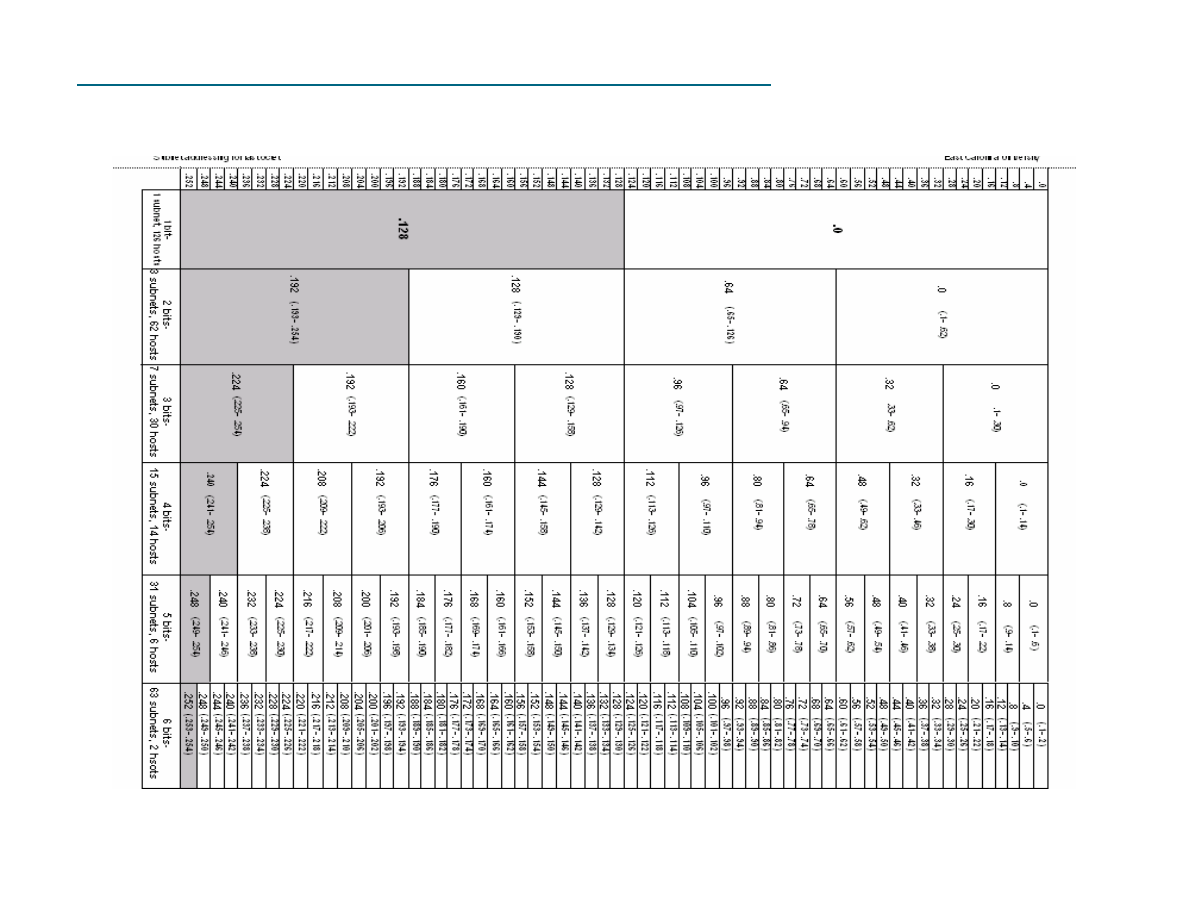
CCNA Exploration
Network Fundamentals: Planning and Cabling Networks
Lab 10.6.1 Creating a Small Lab Topology
All contents are Copyright © 1992–2007 Cisco Systems, Inc. All rights reserved. This document is Cisco Public Information.
Page 8 of 8
Appendix 1
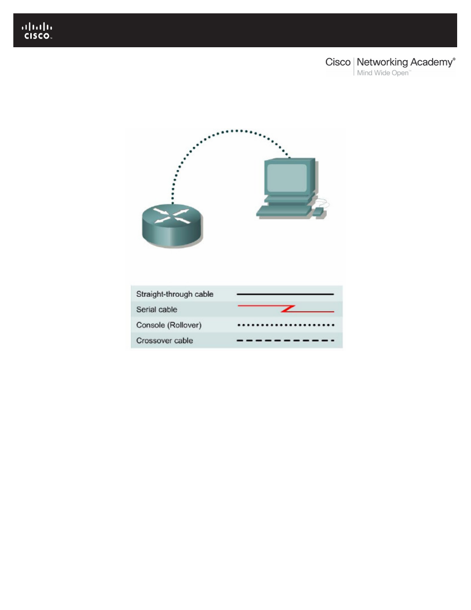
All contents are Copyright © 1992–2007 Cisco Systems, Inc. All rights reserved. This document is Cisco Public Information.
Page 1 of 8
Lab 10.6.2: Establishing a Console Session with HyperTerminal
Topology Diagram
Learning Objectives
Upon completion of this lab, you will be able to:
•
Connect a router and computer using a console cable.
•
Configure HyperTerminal to establish a console session with a Cisco IOS router.
•
Configure HyperTerminal to establish a console session with a Cisco IOS switch.
Background
HyperTerminal is a simple Windows-based terminal emulation program for serial communication that can
be used to connect to the console port on Cisco IOS devices. A serial interface on a computer is
connected to the Cisco device via a rollover cable. Using HyperTerminal is the most basic way to access
a router for checking or changing its configuration. Another popular serial communication utility is
TeraTerm Web. Instructions for TeraTerm Web use are contained in Appendix A.
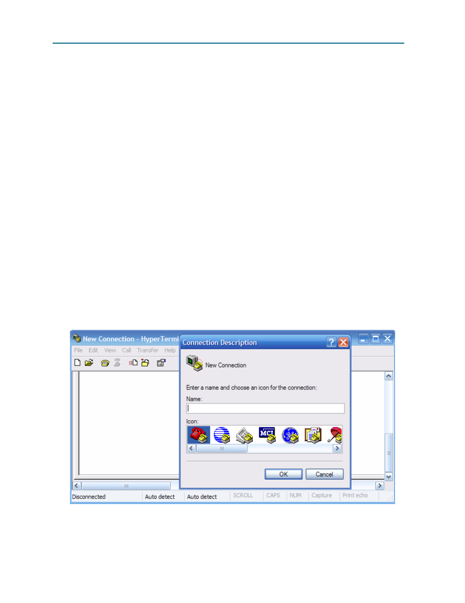
CCNA Exploration
Network Fundamentals: Planning and Cabling Networks
Lab 10.6.2 Establishing a Console Session with HyperTerminal
All contents are Copyright © 1992–2007 Cisco Systems, Inc. All rights reserved. This document is Cisco Public Information.
Page 2 of 8
Scenario
Set up a network similar to the one in the Topology Diagram. Any router that meets the interface
requirements may be used. Possible routers include 800, 1600, 1700, 2500, 2600 routers, or a
combination. The following resources will be required:
•
Computer with a serial interface and HyperTerminal loaded
•
Cisco router
•
Console (rollover) cable for connecting the workstation to the router
Task 1: Connect a Router and Computer with a Console Cable.
Step 1: Set up basic physical connection.
Connect the console (rollover) cable to the console port on the router. Connect the other cable end to the
host computer with a DB-9 or DB-25 adapter to the COM 1 port.
Step 2: Power on devices.
If not already powered on, enable power to the computer and router.
Task 2: Configure HyperTerminal to Establish a Console Session with a Cisco IOS Router.
Step 1: Start HyperTerminal application.
From the Windows taskbar, start the HyperTerminal program by clicking Start > Programs >
Accessories > Communications > HyperTerminal.
Step 2: Configure HyperTerminal.
Figure 1. HyperTerminal Name Configuration Window
Refer to Figure 1 for a description of the opening HyperTerminal configuration window. At the Connection
Description window, enter a session name in the Name field. Select an appropriate icon, or leave the
default. Click OK.
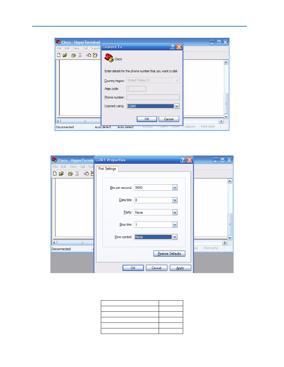
CCNA Exploration
Network Fundamentals: Planning and Cabling Networks
Lab 10.6.2 Establishing a Console Session with HyperTerminal
All contents are Copyright © 1992–2007 Cisco Systems, Inc. All rights reserved. This document is Cisco Public Information.
Page 3 of 8
Figure 2. HyperTerminal Connection Type
Refer to Figure 2. Enter the appropriate connection type, COM 1, in the Connect using field. Click OK.
Figure 3. HyperTerminal COM1 Port Settings
Refer to Figure 3. Change port settings to the following values:
Setting
Value
Bits per second
9600
Data bits
8
Parity
None
Stop bits
1
Flow control
None
CCNA Exploration
Network Fundamentals: Planning and Cabling Networks
Lab 10.6.2 Establishing a Console Session with HyperTerminal
All contents are Copyright © 1992–2007 Cisco Systems, Inc. All rights reserved. This document is Cisco Public Information.
Page 4 of 8
Click OK.
When the HyperTerminal session window comes up, press the Enter key. There should be a response
from the router. This indicates that connection has been successfully completed. If there is no connection,
troubleshoot as necessary. For example, verify that the router has power. Check the connection to the
correct COM 1 port on the PC and the console port on the router. If there is still no connection, ask the
instructor for assistance.
Step 3: Close HyperTerminal.
When finished, close the HyperTerminal session. Click File > Exit. When asked whether to save the
session, click Yes. Enter a name for the session.
Step 4: Reconnect the HyperTerminal session.
Reopen the HyperTerminal session as described in Task 2, Step 1. This time, when the Connection
Description window opens (see Figure 1), click Cancel.
Click File > Open. Select the saved session and then click Open. Use this technique to reconnect the
HyperTerminal session to a Cisco device without reconfiguring a new session.
When finished, exit TeraTerm.
Task 3: Configure HyperTerminal to Establish a Console Session with a Cisco IOS Switch.
Serial connections between Cisco IOS routers and switches are very similar. In this task, you will make a
serial connection between the host computer and a Cisco IOS switch.
Figure 4. Serial Connection Between a Host Computer and Cisco Switch
Step 1: Set up basic physical connection.
Refer to Figure 4. Connect the console (rollover) cable to the console port on the router. Connect the
other cable end to the host computer with a DB-9 or DB-25 adapter to the COM 1 port.
Step 2: Power on devices.
If not already powered on, enable power to the computer and switch.
Step 3: Start HyperTerminal application.
From the Windows taskbar, start the HyperTerminal program by clicking Start > Programs >
Accessories > Communications > Hyper Terminal.

CCNA Exploration
Network Fundamentals: Planning and Cabling Networks
Lab 10.6.2 Establishing a Console Session with HyperTerminal
All contents are Copyright © 1992–2007 Cisco Systems, Inc. All rights reserved. This document is Cisco Public Information.
Page 5 of 8
Step 4: Configure HyperTerminal.
Use the procedure described in Task 2, Step 2, to configure HyperTerminal.
Refer to Figure 1 of the opening HyperTerminal configuration window. At the Connection Description
window, enter a session name in the Name field. Select an appropriate icon, or leave the default. Click
OK.
Refer to Figure 2. Enter the appropriate connection type, COM 1, in the Connect using field. Click OK.
Refer to Figure 3. Change port settings to the following values:
Setting
Value
Bits per second
9600
Data bits
8
Parity
None
Stop bits
1
Flow control
None
Click OK.
When the HyperTerminal session window comes up, press the Enter key. There should be a response
from the switch. This indicates that connection has been successfully completed. If there is no
connection, troubleshoot as necessary. For example, verify that the switch has power. Check the
connection to the correct COM 1 port on the PC and the console port on the switch. If there is still no
connection, ask the instructor for assistance.
Step 5: Close HyperTerminal.
When finished, close the HyperTerminal session. Click File > Exit. When asked whether to save the
session, click No.
Task 3: Reflection
This lab provided information for establishing a console connection to a Cisco IOS router and switch.
Task 4: Challenge
Draw the pin connections for the rollover cable and straight-through cable. Compare the differences, and
be able to identify the different cable types.
Task 5: Clean Up
Unless directed otherwise by the instructor, turn off power to the host computer and router. Remove the
rollover cable.
Remove anything that was brought into the lab, and leave the room ready for the next class.
CCNA Exploration
Network Fundamentals: Planning and Cabling Networks
Lab 10.6.2 Establishing a Console Session with HyperTerminal
All contents are Copyright © 1992–2007 Cisco Systems, Inc. All rights reserved. This document is Cisco Public Information.
Page 6 of 8
Appendix A
Establishing a Console Session with TeraTerm
Topology Diagram
Learning Objectives
Upon completion of this lab, you will be able to:
•
Connect a router and computer using a console cable.
•
Configure TeraTerm to establish a console session with the router.
Background
TeraTerm Web is another simple Windows-based terminal emulation program for serial communication
that can be used to connect to the console port on Cisco IOS devices.
Scenario
Cable a network similar to the Topology Diagram. Any router that meets the interface requirements may
be used. Possible routers include 800, 1600, 1700, 2500, 2600 routers, or a combination. The following
resources will be required:
•
Computer with a serial interface and TeraTerm Pro loaded
•
Cisco router
•
Console (rollover) cable for connecting the workstation to the router
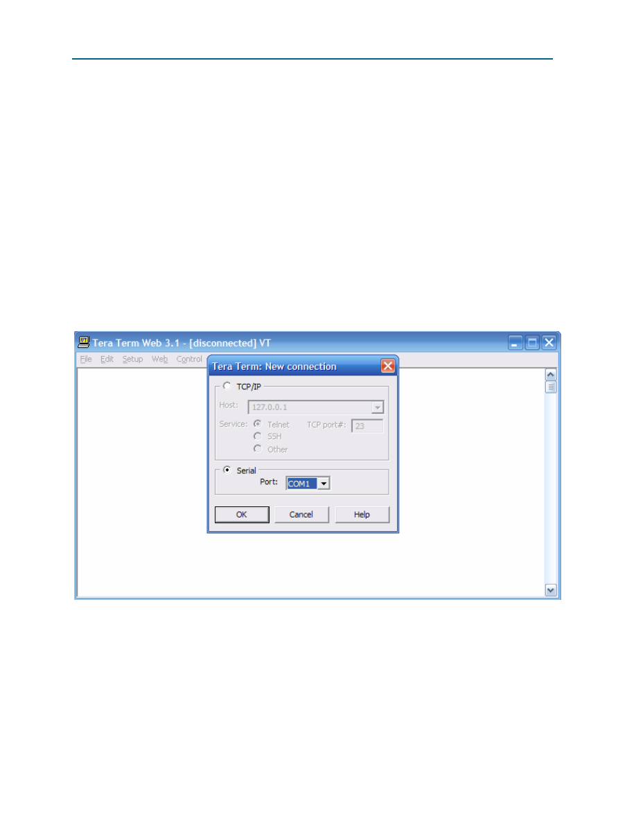
CCNA Exploration
Network Fundamentals: Planning and Cabling Networks
Lab 10.6.2 Establishing a Console Session with HyperTerminal
All contents are Copyright © 1992–2007 Cisco Systems, Inc. All rights reserved. This document is Cisco Public Information.
Page 7 of 8
Task 1: Connect a Router and Computer with a Console Cable.
Step 1: Set up basic physical connection.
Ensure that power is turned off on the computer and Cisco router. Connect the console (rollover) cable to
the console port on the router. Connect the other cable end to the PC with a DB-9 or DB-25 adapter to
the COM 1 port.
Step 2: Power on devices.
Enable power to the computer and router.
Task 2: Configure TeraTerm Web to Establish a Console Session with the Router.
Step 1: Start TeraTerm Web application.
From the Windows taskbar, start the TeraTerm Web program by opening the TeraTerm Web folder, and
starting the TeraTerm Web application, ttermpro.
Step 2: Configure TeraTerm Web.
Figure 1. TeraTerm Web Connection Configuration Window
Click File > New Connection. Refer to Figure 1. Select the appropriate serial COM port. Click OK.
When the TeraTerm Web session window comes up, press the Enter key. There should be a response
from the router. The connection has been successfully completed. If there is no connection, troubleshoot
as necessary. For example, verify that the router has power. Check the connection to the COM 1 port on
the PC and the console port on the router. If there is still no connection, ask the instructor for assistance.
Step 3: Close TeraTerm Web.
When finished, close the TeraTerm Web session. Click File | Exit. When asked whether to save the
session, click Yes. Enter a name for the session.

CCNA Exploration
Network Fundamentals: Planning and Cabling Networks
Lab 10.6.2 Establishing a Console Session with HyperTerminal
All contents are Copyright © 1992–2007 Cisco Systems, Inc. All rights reserved. This document is Cisco Public Information.
Page 8 of 8
Step 4: Reconnect the TeraTerm Web session.
Reopen the TeraTerm Web session as described in Task 2, Step 1. This time, when the New Description
window opens (see Figure 1), click Cancel.
Click File > Open. Select the saved session and then click Open. Use this technique to reconnect the
TeraTerm Web session to a Cisco device without reconfiguring a new session.
Task 3: Reflection
This lab provided information for establishing a console connection to a Cisco router. Cisco switches are
accessed in the same way.
Task 4: Challenge
Draw the pin connections for the rollover cable and straight-through cable. Compare the differences, and
be able to identify the different cable types.
Task 5: Clean Up
Unless directed otherwise by the instructor, turn off power to the host computer and router. Remove the
rollover cable.
Remove anything that was brought into the lab, and leave the room ready for the next class.
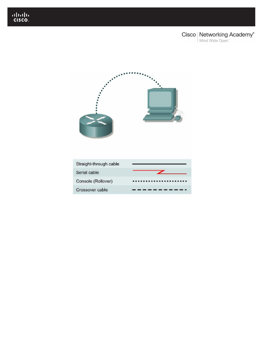
All contents are Copyright © 1992–2007 Cisco Systems, Inc. All rights reserved. This document is Cisco Public Information.
Page 1 of 4
Lab 10.6.3: Establishing a Console Session with Minicom
Topology Diagram
Learning Objectives
Upon completion of this lab, you will be able to:
•
Connect a router and computer using a console cable.
•
Configure Minicom to establish a console session with the router.
•
Perform basic commands.
Background
Minicom is a text-based UNIX terminal emulation program, similar to the Windows HyperTerminal
program. Minicom can be used for many purposes, such as controlling a modem or accessing a Cisco
router through the serial console connection. The Linux or UNIX operating system is required.
Scenario
Set up a network similar to the one in the Topology Diagram. Any router that meets the interface
requirements may be used. Possible routers include 800, 1600, 1700, 2500, 2600 routers, or a
combination. The following resources will be required:
•
Linux/UNIX computer with a serial interface and Minicom loaded
•
Cisco router
•
Console (rollover) cable for connecting the workstation to the router
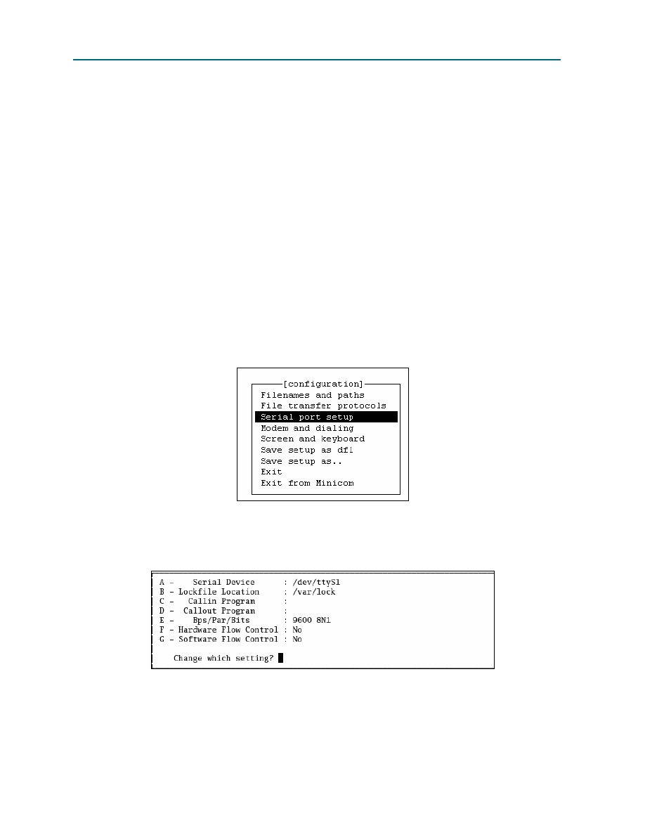
CCNA Exploration
Network Fundamentals: Planning and Cabling Networks
Lab 10.6.3 Establishing a Console Session with Minicom
All contents are Copyright © 1992–2007 Cisco Systems, Inc. All rights reserved. This document is Cisco Public Information.
Page 2 of 4
Task 1: Connect a Router and Computer with a Console Cable.
Step 1: Set up basic physical connection.
Ensure that power is turned off on the computer and Cisco router. Connect the console (rollover) cable to
the console port on the router. Connect the other cable end to the PC with a DB-9 or DB-25 adapter to
the COM 1 port.
Step 2: Power on devices.
Enable power to the computer and router.
Task 2: Configure Minicom to Establish a Console Session with the Router.
Step 1: Start Minicom application in configuration mode.
Note: To configure Minicom, root access is required. From the Linux command prompt, start minicom
with the –s option. This starts Minicom in the configuration mode:
[root]# minicom –s <ENTER>
Step 2: Configure Minicom for serial communications.
Figure 1. Main Configuration Window
Refer to Figure 1. To configure the serial port, scroll down the configuration list and select Serial port
setup
. Press Enter.
Figure 2. Serial Port Configuration Window
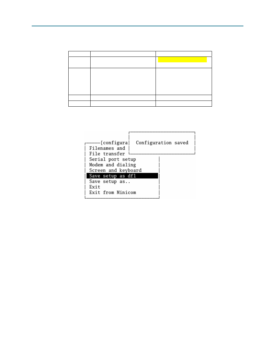
CCNA Exploration
Network Fundamentals: Planning and Cabling Networks
Lab 10.6.3 Establishing a Console Session with Minicom
All contents are Copyright © 1992–2007 Cisco Systems, Inc. All rights reserved. This document is Cisco Public Information.
Page 3 of 4
Refer to Figure 2. Use the letter by the field to change a setting. Refer to Table 1 for the correct values.
Option
Field
Value
A
Serial Device
/dev/ttyS0
for COM1
/dev/ttyS1
for COM2
E
Bps/Par/Bits
Bps- 9600
Par- None
Bits- 8
Stop bits- 1
(or, select option ‘Q’)
F
Hardware Flow Control
Toggle- No
G
Software Flow Control
Toggle- No
Table 1. Serial Port Settings
Return to the Configuration menu by pressing Enter or Esc.
Figure 3. Serial Port Configuration Window
Refer to Figure 3. Select Save setup as dfl (default file). When Minicom is restarted, the default
values will be reloaded.
Step 3: Close Minicom.
When finished, close the Minicom session. Select Exit from Minicom.
Step 4: Restart the Minicom session.
[root]# minicom <ENTER>
When the session window starts, press the Enter key. There should be a response from the router. This
indicates that connection has been successfully completed. If there is no connection, troubleshoot as
necessary. For example, verify that the router has power. Check the connection to the correct COM1 port
on the PC and the console port on the router. If there is still no connection, ask the instructor for
assistance.
Task 3: Perform Basic Commands.
Minicom is a text-based, menu-driven, serial communication utility. Basic commands are not intuitive. For
example, users communicate with remote devices within the terminal window. However, to control the
utility, use <CTRL> A. To get help, press <CTRL> A, followed by Z.
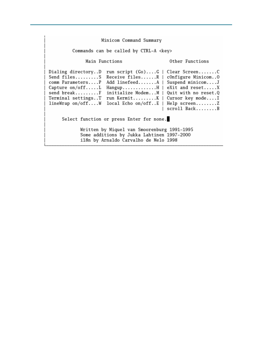
CCNA Exploration
Network Fundamentals: Planning and Cabling Networks
Lab 10.6.3 Establishing a Console Session with Minicom
All contents are Copyright © 1992–2007 Cisco Systems, Inc. All rights reserved. This document is Cisco Public Information.
Page 4 of 4
Figure 4. Minicom Command Summary Screen
Refer to Figure 4 for a list of functions and corresponding keys. To quit Minicom, press <CTRL> A,
followed by either Q or X.
Task 4: Reflection
This lab provided information for establishing a console connection to a Cisco router using Minicom.
Cisco switches are accessed in the same fashion.
Task 5: Clean Up
Unless directed otherwise by the instructor, turn off power to the host computer and router. Remove the
rollover cable.
Remove anything that was brought into the lab, and leave the room ready for the next class.
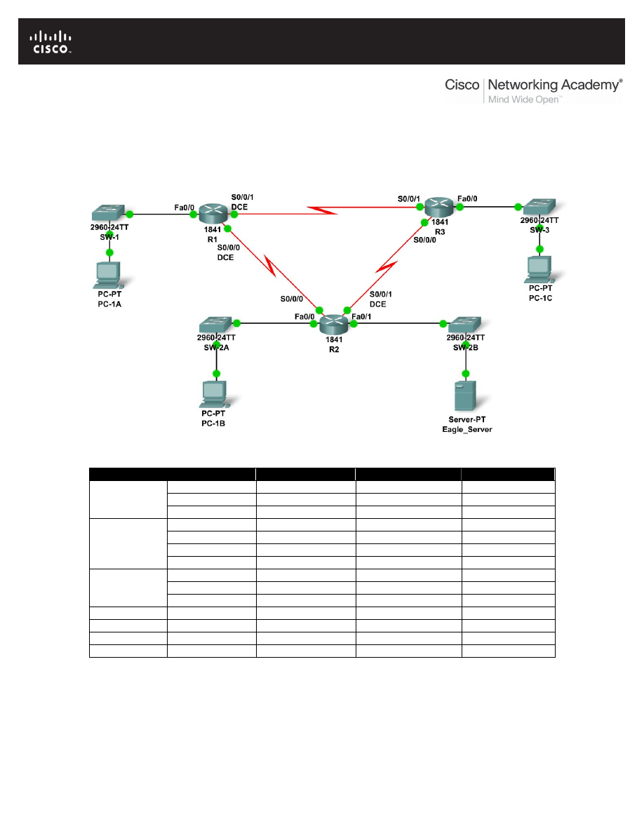
All contents are Copyright © 1992–2007 Cisco Systems, Inc. All rights reserved. This document is Cisco Public Information.
Page 1 of 3
10.7.1: Skills Integration Challenge: Network Planning and
Interface Configuration
Topology Diagram
Addressing Table
Device
Interface
IP Address
Subnet Mask
Default Gateway
Fa0/0
N/A
S0/0/0
N/A
R1
S0/0/1
N/A
Fa0/0
N/A
Fa0/1
N/A
S0/0/0
N/A
R2
S0/0/1
N/A
Fa0/0
N/A
S0/0/0
N/A
R3
S0/0/1
N/A
PC-1A
NIC
PC-2A
NIC
PC-3A
NIC
Eagle_Server
NIC

CCNA Exploration
Network Fundamentals:
Planning and Cabling Networks 10.7.1: Skills Integration Challenge: Network Planning and Interface Configuration
All contents are Copyright © 1992–2007 Cisco Systems, Inc. All rights reserved. This document is Cisco Public Information.
Page 2 of 3
Learning Objectives
Upon completion of this lab, you will be able to:
•
Build the network topology.
•
Plan the IP addresses.
•
Configure router and PC interfaces.
•
Test the network.
Background
Practice your network building, planning, and configuration skills. Device names and routing have
already been configured.
Task 1: Build the Network Topology.
Use the following charts, and the devices in the Device Pool, to create the topology.
Routers:
Hostname
Interface
Connects To
Interface
R1
Fa0/0
SW-1
Fa0/1
R1
S0/0/0 (DCE)
R2
S0/0/0
R1
S0/0/1 (DCE)
R3
S0/0/1
R2
Fa0/0
SW-2A
Fa0/1
R2
S0/0/1 (DCE)
R3
S0/0/0
R2
Fa0/1
SW-2B
Fa0/1
R3
Fa0/0
SW-3
Fa0/1
Switches:
Hostname
Interface
Connects To
Interface
SW-1
Fa0/2
PC-1A
FastEthernet
SW-2A
Fa0/2
PC-1B
FastEthernet
SW-2B
Fa0/2
Eagle_Server
FastEthernet
SW-3
Fa0/2
PC-1C
FastEthernet
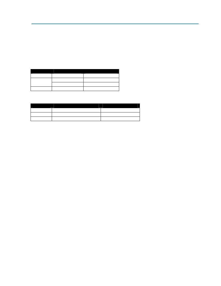
CCNA Exploration
Network Fundamentals:
Planning and Cabling Networks 10.7.1: Skills Integration Challenge: Network Planning and Interface Configuration
All contents are Copyright © 1992–2007 Cisco Systems, Inc. All rights reserved. This document is Cisco Public Information.
Page 3 of 3
Task 2: Create and Assign an Addressing Scheme.
You are asked to use the 192.168.1.0 /24 address space. Seven total networks are required;
assign the networks in decreasing order of number of hosts required for efficient use of address
space. Use the following charts to create an effective addressing scheme:
LAN:
Hostname
Interface
Number of Hosts
R1
Fa0/0
60
Fa0/0
10
R2
Fa0/1
30
R3
Fa0/0
7
WAN:
Hostname
Address to be Assigned
Number of Hosts
R1-R2
R1-First host address
2
R1-R3
R1-First host address
2
R2-R3
R2-First host address
2
Use the following rules to assign the IP addresses.
•
PCs will use the first host address in the subnet; the server will use the second to last
host address in its subnet.
•
All FastEthernet ports on a router will use the last host address of the assigned subnet.
•
The R1-R2 link will use the first WAN subnet, the R1-R3 link will use the second WAN
subnet, and the R2-R3 link will use the third WAN subnet. R1 and R2 DCE interfaces
should have clock rates of 56000.
Task 3: Interface Configuration
Perform interface configuration of the R1, R2, and R3 routers, the PCs, and the server according
to the addressing scheme above.
Task 4: Testing Connectivity
Make sure all PCs can ping their gateways, other PCs, and the server.
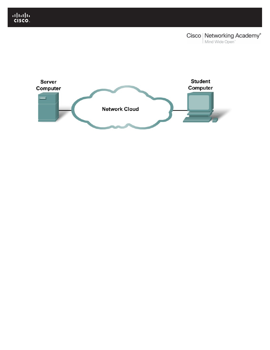
All contents are Copyright © 1992–2007 Cisco Systems, Inc. All rights reserved. This document is Cisco Public Information.
Page 1 of 9
11.4.3.3: Network Latency Documentation with Ping
Topology Diagram
Learning Objectives
•
Use the ping command to document network latency.
•
Compute various statistics on the output of a ping capture.
•
Measure delay effects from larger datagrams.
Background
To obtain realistic network latency statistics, this activity must be performed on a live network. Be sure to
check with your instructor for any local security restrictions against using the ping command on the
network.
The destination Server Computer must return ECHO replies, otherwise delay cannot be computed. Some
computers have this feature disabled through a firewall, and some private networks block transit ECHO
datagrams. For this experiment to be interesting, a sufficiently distant destination should be chosen. For
example, destinations on the same LAN or within a few hops may return an unrepresentative low latency.
With patience, a suitable destination will be found.
The purpose of this lab is to measure and evaluate network latency over time, and during different
periods of the day to capture a representative sample of typical network activity. This will be
accomplished by analyzing the return delay from a distant computer with the ping command.
Statistical analysis of throughput delay will be performed with the assistance of a spreadsheet application
such as Microsoft Excel. Return delay times, measured in milliseconds, will be summarized with through
computation of the average latency (mean), noting the latency value at the center of the ordered range of
latency points (median), and identification of the most frequently occurring delay (mode). The Appendix
contains a chart that can be submitted to the instructor when finished.
Delay will also be measured when the ICMP datagram size is increased.

CCNA Exploration
Network Fundamentals:
Configuring and Testing Your Network
11.4.3.3: Network Latency Documentation with Ping
All contents are Copyright © 1992–2007 Cisco Systems, Inc. All rights reserved. This document is Cisco Public Information.
Page 2 of 9
Scenario
In the topology graphic above, the network cloud represents all of the network devices and cabling
between the student computer and the destination Server Computer. It is normally these devices that
introduce network latency. Network engineers routinely rely on networks outside of local administration for
connectivity to external networks. Monitoring path latency does provide some measure of administrative
diligence, which may be used in decision-making when evaluating suitable applications for wide area
network (WAN) deployment.
This activity will require five days of testing. On each day, three tests will be performed. Preferably, one
test will be made in the early morning, one around mid-day, and one in the evening. The idea is to note
and document latency differences that occur during the different periods of the day. When finished there
will be a total of 15 sets of this data.
To understand the delay effects from larger datagrams, ICMP datagrams will be sent with increasingly
larger datagrams and analyzed.
Task 1: Use the ping Command to Document Network Latency.
Step 1: Verify connectivity between Student Computer and destination Server Computer.
To verify connectivity between the Student Computer and destination Server Computer, open a terminal
window by clicking on start | run. Enter cmd, and then select OK. Attempt to ping a suitably distant
destination, such as www.yahoo.com:
C:\>
ping -n 1 www.yahoo.com
Pinging www.yahoo-ht3.akadns.net [209.191.93.52] with 32 bytes of data:
Reply from 209.191.93.52: bytes=32 time=304ms TTL=52
Ping statistics for 209.191.93.5:
Packets: Sent = 1, Received = 1, Lost = 0 (0% loss)
Approximate round trip times in milli-seconds:
Minimum = 304ms, Maximum = 304ms , Average = 304 ms
Use the ping /? command to answer the following questions:
What is the purpose of the –n option and argument 1?
____________________________________________________________________________________
____________________________________________________________________________________
What option and argument would change the default size to 100 bytes? _______________
Decide on a destination Server Computer, and write down the name: _____________
Use the ping command to verify connectivity with the destination, and write down the results:
Packets sent
Packets Received
Packets Lost
If there are lost packets, use another destination and retest.
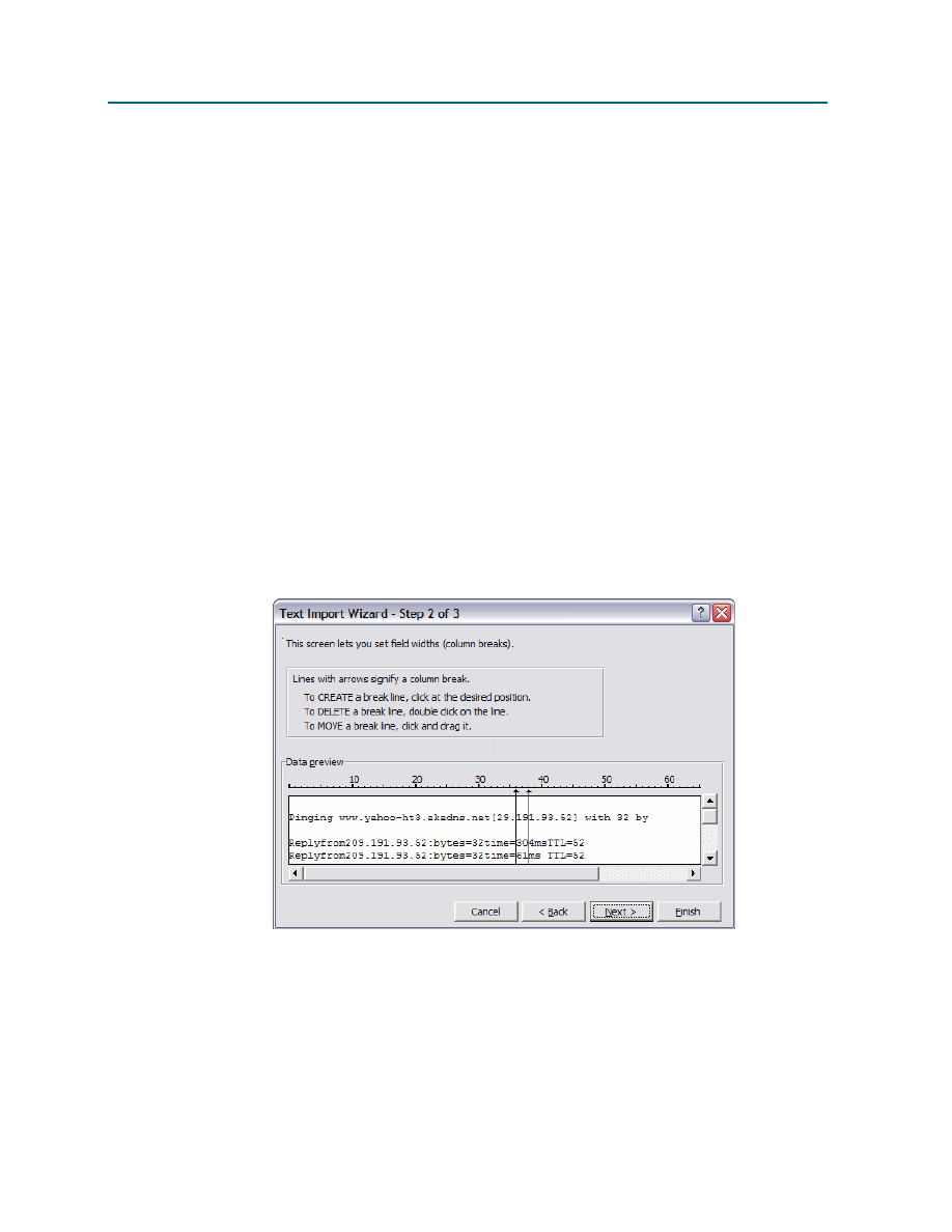
CCNA Exploration
Network Fundamentals:
Configuring and Testing Your Network
11.4.3.3: Network Latency Documentation with Ping
All contents are Copyright © 1992–2007 Cisco Systems, Inc. All rights reserved. This document is Cisco Public Information.
Page 3 of 9
Step 2: Perform a delay test.
Write down the command that will send 100 ECHO requests to the destination:
____________________________________________________________________________________
Use the ping command to send 100 ECHO requests to your destination. When finished, copy the replies
into Notepad. Notepad can be opened by clicking on Start | Programs | Accessories, and select Notepad.
Save the file using the name format day-sample#.txt, where: day = the day the test was performed
(1-5), and sample# = the sample period (1-3).
Alternately, output can be redirected to a file by appending > day-sample#.txt to the end of the ping
command. NOTE: the terminal will remain blank until the command has finished.
Task 2: Compute Various Statistics on the Output of a ping Capture.
Step 1: Bring the text file into the Excel Spreadsheet Application.
If not already opened, start Microsoft Excel. Select menu options File | Open. Use Browse to move to the
directory that holds the text file. Highlight the filename and select Open. To format a text file for use within
Excel, insure all numeric values are separated from text characters. In the Text Import Wizard, Step 1,
select Fixed Width. In Step 2, follow instructions in the window to separate numeric values from text
values. Refer to Figure 1.
Figure 1. Excel Text Import Wizard.
Step 2. Compute mean, median and mode delay values.
When input formatting is satisfactory, select Finish. If the spreadsheet has numbers in different fields,
manually fix the numbers. After the spreadsheet has been opened, format the columns so they are more
readable. When complete, you should have a spreadsheet that looks similar to Figure 2.
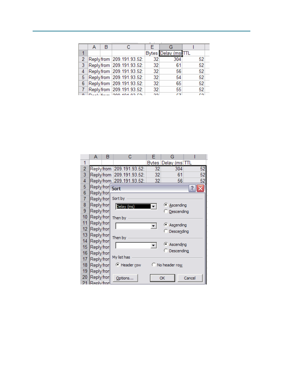
CCNA Exploration
Network Fundamentals:
Configuring and Testing Your Network
11.4.3.3: Network Latency Documentation with Ping
All contents are Copyright © 1992–2007 Cisco Systems, Inc. All rights reserved. This document is Cisco Public Information.
Page 4 of 9
Figure 2. Partial spreadsheet correctly formatted.
Record the number of dropped packets in your chart, column Dropped Packets. Dropped packets will
have a consistently large delay value.
Finally, the delay values must be ordered (sorted) when computing the median and mode values. This is
accomplished with the Data | Sort menu options. Highlight all of the data fields. Figure 3 shows a partial
spreadsheet highlighted and the Data | Sort menu opened. If a header row was highlighted, click on the
Header row radio button. Select the column that contains the Delay values, in Figure 3 it is Column G.
When finished click OK.
Figure 3. Ordering on the Delay column.
The formula used to compute the mean, or average, delay is the sum of the delays, divided by number of
measurements. Using the example above, this would equate to the formula in cell G102:
=average(G2:G101)
. Perform a visual ‘sanity check’ to verify your mean value is approximately the
value shown. Record this number in your chart, under column Mean.
The formula used to compute the median delay, or the delay value in the center of the ordered range, is
similar to the average formula, above. For the median value, the formula in cell G103 would be

CCNA Exploration
Network Fundamentals:
Configuring and Testing Your Network
11.4.3.3: Network Latency Documentation with Ping
All contents are Copyright © 1992–2007 Cisco Systems, Inc. All rights reserved. This document is Cisco Public Information.
Page 5 of 9
=median(G2:G101)
. Perform a visual ‘sanity check’ to verify your median value is similar to what is
shown midway in the data range. Record this number in your chart, under column Median.
The formula used to compute the modal delay, or the delay value that is the most frequently occurring, is
also similar. For the mode value, the formula in cell G104 would be =mode(G2:G101). Perform a visual
‘sanity check’ to verify your mode value is the most frequently occurring value in the data range. Record
this number in your chart, under column Mode.
The new spreadsheet file may be saved or discarded as desired, but the data text file should be retained.
Task 3: Measure Delay Effects from Larger Datagrams.
To determine if larger datagrams affect delay, increasingly larger ECHO requests will be sent to the
destination. In this analysis, 20 datagrams will be incremented by 100 bytes per ping request. A
spreadsheet will be created with the reply results, and a chart that plots size vs. delay will be produced.
Step 1: Perform a variable sized delay test.
The easiest way to accomplish this task is to use the Windows built-in FOR loop command. The syntax is:
FOR /L %variable IN (start,step,end) DO command [command-parameters]
The set is a sequence of numbers from start to end, by step amount. So
(1,1,5) would generate the sequence 1 2 3 4 5 and (5,-1,1) would generate the
sequence (5 4 3 2 1)
In the following command, destination is the destination. Issue the command:
FOR /L %i IN (100,100,2000) DO ping -n 1 -l %i destination
Copy the output into Notepad, and save the file using the name variablesizedelay.txt.
To redirect output to a file, use the redirect append operator, >>, as shown below. The normal redirect
operator, >, will clobber the file each time the ping command is executed and only the last reply will be
saved. NOTE: the terminal will remain blank until the command has finished:
FOR /L %i IN (100,100,2000) DO ping -n 1 -l %i destination >>
variablesizedelay.txt
The output of one line is shown below. All 20 replies are arranged similarly:
C:\>
FOR /L %i IN (100,100,2000) DO ping –n 1 –l %i
www.yahoo.com
C:\> ping -n 1 -l 100 www.yahoo.com
Pinging www.yahoo-ht3.akadns.net [209.191.93.52] with 100 bytes of data:
Reply from 209.191.93.52: bytes=100 time=383ms TTL=52
Ping statistics for 209.191.93.52:
Packets: Sent = 1, Received = 1, Lost = 0 (0% loss),
Approximate round trip times in milli-seconds:
Minimum = 383ms, Maximum = 383ms, Average = 383ms
Step 2: Bring the text file into the Excel Spreadsheet Application.
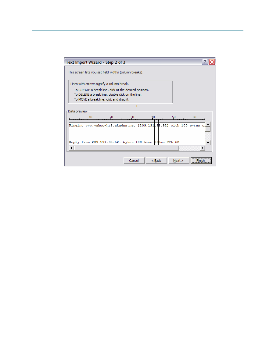
CCNA Exploration
Network Fundamentals:
Configuring and Testing Your Network
11.4.3.3: Network Latency Documentation with Ping
All contents are Copyright © 1992–2007 Cisco Systems, Inc. All rights reserved. This document is Cisco Public Information.
Page 6 of 9
Open the new text file in Excel. Refer to Figure 4.
Figure 4. Excel Text Import Wizard.
The difference between this file and the previous file is that the variable size file has much more
information than is really needed.
Step 3: Format the spreadsheet.
Clean and organize the spreadsheet data into two columns, Bytes and Delay. When finished, the
spreadsheet should look similar to Figure 5.
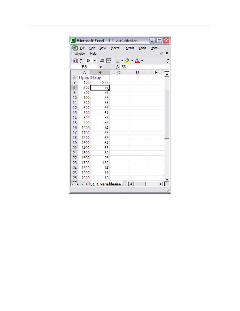
CCNA Exploration
Network Fundamentals:
Configuring and Testing Your Network
11.4.3.3: Network Latency Documentation with Ping
All contents are Copyright © 1992–2007 Cisco Systems, Inc. All rights reserved. This document is Cisco Public Information.
Page 7 of 9
Figure 5. Formatted Spreadsheet.
Step 3: Create a chart of the data.
Highlight the Delay column data. Select menu options Insert | Chart. There are a number of charts that
can be used to display delay data, some better than others. While a chart should be clear, there is room
for individual creativity. The chart is Figure 6 is a Stacked Line chart.
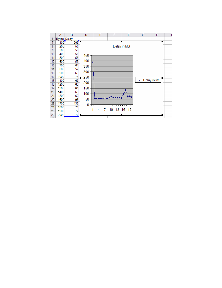
CCNA Exploration
Network Fundamentals:
Configuring and Testing Your Network
11.4.3.3: Network Latency Documentation with Ping
All contents are Copyright © 1992–2007 Cisco Systems, Inc. All rights reserved. This document is Cisco Public Information.
Page 8 of 9
Figure 6. Plot of Delay vs. datagram size.
When finished, save your spreadsheet and chart and submit it to your instructor with the final delay
analysis.
Are there any assumptions that can be made regarding delay when larger datagrams are sent across a
network?
____________________________________________________________________________________
____________________________________________________________________________________
Task 4: Reflection
The ping command can provide important network latency information. Careful delay analysis over
successive days and during different periods of the day can alert the network engineer to changes in
network performance. For example, network devices may become overwhelmed during certain periods of
the day, and network delay will spike. In this case, routine data transfers should be scheduled during off-
peak times when delay is less. Also, many users subscribe to peer-to-peer applications such as KaZaA
and Napster. When these file-sharing applications are active, valuable bandwidth will be diverted from
critical business applications. If delays are caused by events within the organization, network analysis
tools can be used to determine the source and corrective action taken. When the source originates from
external networks, not under the control of the organization, subscribing with a different or additional
Internet service provider (ISP) may prove beneficial.
Task 5: Challenge
If permitted, download a large file and perform a separate delay test while the file is downloading. Write a
one or two paragraph analysis that compares these delay results against a measurement made without
the download.

CCNA Exploration
Network Fundamentals:
Configuring and Testing Your Network
11.4.3.3: Network Latency Documentation with Ping
All contents are Copyright © 1992–2007 Cisco Systems, Inc. All rights reserved. This document is Cisco Public Information.
Page 9 of 9
Appendix
NAME: ________________________ Network Delay Documentation
Source IP Address: ______________ Destination IP Address:_____________ TTL: ______
Statistical Analysis of Network Latency with 32 byte datagrams
Day
(1-5)
Date
(mm/dd/yyyy)
Time
(hh:mm)
MEAN
MEDIAN
MODE
Dropped
Packets
1
2
3
4
5
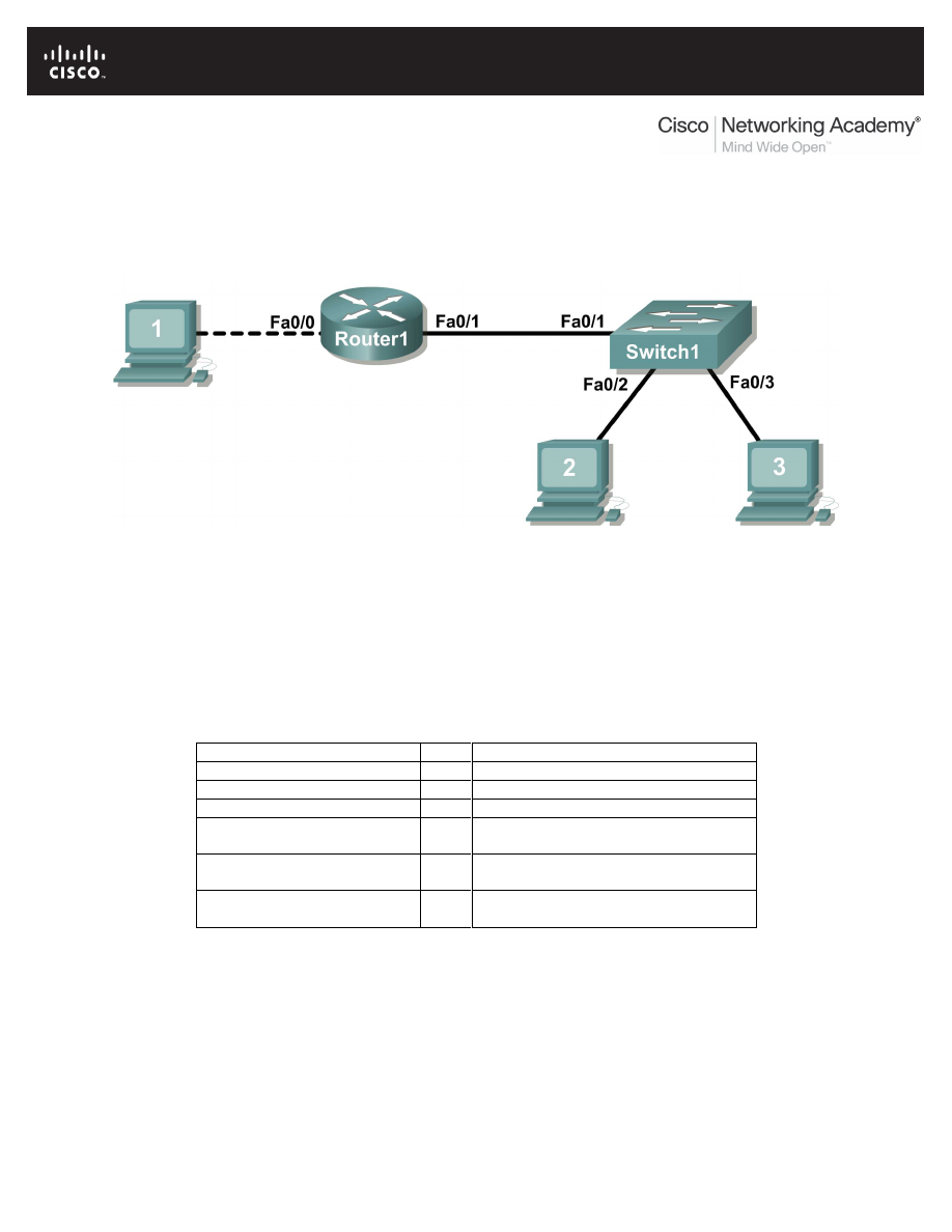
All contents are Copyright © 1992–2007 Cisco Systems, Inc. All rights reserved. This document is Cisco Public Information.
Page 1 of 20
Lab 11.5.1: Basic Cisco Device Configuration
Topology Diagram
Learning Objectives
•
Configure Cisco router global configuration settings.
•
Configure Cisco router password access.
•
Configure Cisco router interfaces.
•
Save the router configuration file.
•
Configure a Cisco switch.
Background
Hardware
Qty
Description
Cisco Router
1
Part of CCNA Lab bundle.
Cisco Switch
1
Part of CCNA Lab bundle.
*Computer (host)
1
Lab computer.
Console (rollover) cable
1
Connects computer host 1 to Router
console port.
UTP Cat 5 crossover cable
1
Connects computer host 1 to Router
LAN interface Fa0/0
Straight Through Cable
3
Connects computer hosts to Switch
and switch to router
Table 1. Equipment and hardware required for this lab.
Gather the necessary equipment and cables. To configure the lab, make sure the equipment listed in
Table 1 is available.
Common configuration tasks include setting the hostname, access passwords, and MOTD banner.
Interface configuration is extremely important. In addition to assigning a Layer 3 IP address, enter a
description that describes the destination connection speeds troubleshooting time.

CCNA Exploration
Network Fundamentals:
Configuring and Testing Your Network
Lab 11.5.1 Basic Cisco Device Configuration
All contents are Copyright © 1992–2007 Cisco Systems, Inc. All rights reserved. This document is Cisco Public Information.
Page 2 of 20
Configuration changes are effective immediately.
Configuration changes must be saved in NVRAM to be persistent across reboot.
Configuration changes may also be saved off-line in a text file for auditing or device replacement.
Cisco IOS switch configuration is similar to Cisco IOS router configuration.
Scenario
In this lab students will configure common settings on a Cisco Router and Cisco Switch.
Given an IP address of
198.133.219.0/24
, with 4 bits borrowed for subnets, fill in the following
information in the table below.
(Hint: fill in the subnet number, then the host address. Address information will be easy to compute with
the subnet number filled in first)
Maximum number of usable subnets (including the 0
th
subnet): _______________
Number of usable hosts per subnet: ___________________
IP Address:
Subnet mask:
#
Subnet
First host address Last host
address
Broadcast
0
Before proceeding, verify your addresses with the instructor. The instructor will assign subnetworks.
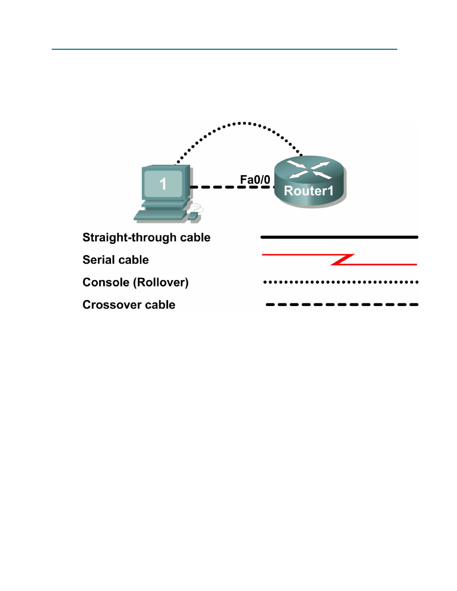
CCNA Exploration
Network Fundamentals:
Configuring and Testing Your Network
Lab 11.5.1 Basic Cisco Device Configuration
All contents are Copyright © 1992–2007 Cisco Systems, Inc. All rights reserved. This document is Cisco Public Information.
Page 3 of 20
Task 1: Configure Cisco Router Global Configuration Settings.
Figure 1. Lab cabling.
Step 1: Physically connect devices.
Refer to Figure 1. Connect the console or rollover cable to the console port on the router. Connect the
other end of the cable to the host computer using a DB-9 or DB-25 adapter to the COM 1 port. Connect
the crossover cable between the host computer’s network interface card (NIC) and Router interface
Fa0/0. Connect a straight-through cable between the Router interface Fa0/1 and any of the switch’s
interfaces (1-24).
Ensure that power has been applied to the host computer, switch and router.
Step 2: Connect host computer to router through HyperTerminal.
From the Widows taskbar, start the HyperTerminal program by clicking on Start | Programs | Accessories
| Communications | HyperTerminal.
Configure HyperTerminal with the proper settings:
Connection Description
Name: Lab 11_2_11
Icon: Personal choice
Connect to
Connect Using:
COM1 (or appropriate COM port)

CCNA Exploration
Network Fundamentals:
Configuring and Testing Your Network
Lab 11.5.1 Basic Cisco Device Configuration
All contents are Copyright © 1992–2007 Cisco Systems, Inc. All rights reserved. This document is Cisco Public Information.
Page 4 of 20
COM1 Properties
Bits per second:
9600
Data bits:
8
Parity:
None
Stop bits:
1
Flow Control:
None
When the HyperTerminal session window comes up, press the Enter key until there is a response from
the router.
If the router terminal is in the configuration mode, exit by typing NO.
Would you like to enter the initial configuration dialog? [yes/no]:
no
Press RETURN to get started!
Router>
When in privileged exec command mode, any misspelled or unrecognized commands will attempt to be
translated by the router as a domain name. Since there is no domain server configured, there will be a
delay while the request times out. This can take between several seconds to several minutes. To
terminate the wait, simultaneously hold down the <CTRL><SHIFT>6 keys then release and press x:
Router>enabel
Translating "enabel"...domain server (255.255.255.255) %
Briefly hold down the keys <CTRL><SHIFT>6, release and press x
Name lookup aborted
Router>
From the user exec mode, enter privileged exec mode:
Router>
enable
Router#
Verify a clean configuration file with the privileged exec command show running-config. If a
configuration file was previously saved, it will have to be removed. Appendix 1 shows a typical default
router’s configuration. Depending on router’s model and IOS version, your configuration may look slightly
different. However, there should be no configured passwords or IP addresses. If your router does not
have a default configuration, ask the instructor to remove the configuration.
Step 3: Configure global configuration hostname setting.
What two commands may be used to leave the privileged exec mode? ___________________
What shortcut command can be used to enter the privileged exec mode? _________________

CCNA Exploration
Network Fundamentals:
Configuring and Testing Your Network
Lab 11.5.1 Basic Cisco Device Configuration
All contents are Copyright © 1992–2007 Cisco Systems, Inc. All rights reserved. This document is Cisco Public Information.
Page 5 of 20
Examine the different configuration modes that can be entered with the command configure? Write
down the list of configuration modes and description:
___________________________________________________________________________________
___________________________________________________________________________________
___________________________________________________________________________________
___________________________________________________________________________________
___________________________________________________________________________________
___________________________________________________________________________________
From the privileged exec mode, enter global configuration mode:
Router#
configuration terminal
Router(config)#
What three commands may be used to leave the global configuration mode and return to the privileged
exec mode?
___________________________________________________________________________________
___________________________________________________________________________________
What shortcut command can be used to enter the global configuration mode? ______________________
Set the device hostname to Router1:
router(config)#
hostname Router1
Router1(config)#
How can the hostname be removed?
___________________________________________________________________________________
___________________________________________________________________________________
Step 5: Configure the MOTD banner.
In production networks, banner content may have a significant legal impact on the organization. For
example, a friendly “Welcome” message may be interpreted by a court that an attacker has been granted
permission to hack into the router. A banner should include information about authorization, penalties for
unauthorized access, connection logging, and applicable local laws. The corporate security policy should
provide policy on all banner messages.

CCNA Exploration
Network Fundamentals:
Configuring and Testing Your Network
Lab 11.5.1 Basic Cisco Device Configuration
All contents are Copyright © 1992–2007 Cisco Systems, Inc. All rights reserved. This document is Cisco Public Information.
Page 6 of 20
Create a suitable MOTD banner. Only system administrators of the ABC Company are authorized access,
unauthorized access will be prosecuted, and all connection information will be logged.
___________________________________________________________________________________
___________________________________________________________________________________
___________________________________________________________________________________
___________________________________________________________________________________
___________________________________________________________________________________
___________________________________________________________________________________
Examine the different banner modes that can be entered. Write down the list of banner modes and
description.
Router1(config)# banner ?
___________________________________________________________________________________
___________________________________________________________________________________
___________________________________________________________________________________
___________________________________________________________________________________
___________________________________________________________________________________
___________________________________________________________________________________
Choose a terminating character that will not be used in the message text.__________________
Configure the MOTD banner. The MOTD banner is displayed on all connections before the login prompt.
Use the terminating character on a blank line to end the MOTD entry:
Router1(config)#
banner motd %
Enter TEXT message. End with the character '%'
***You are connected to an ABC network device. Access is granted to only
current ABC company system administrators with prior written approval. ***
*** Unauthorized access is prohibited, and will be prosecuted. ***
*** All connections are continuously logged. ***
%
Router1(config)#
What is the global configuration command to remove the MOTD banner?
___________________________________________________________________________________

CCNA Exploration
Network Fundamentals:
Configuring and Testing Your Network
Lab 11.5.1 Basic Cisco Device Configuration
All contents are Copyright © 1992–2007 Cisco Systems, Inc. All rights reserved. This document is Cisco Public Information.
Page 7 of 20
Task 2: Configure Cisco router password access.
Access passwords are set for the privileged exec mode and user entry point such as console, aux, and
virtual lines. The privileged exec mode password is the most critical password, since it controls access to
the configuration mode.
Step 1: Configure the privileged exec password.
Cisco IOS supports two commands that set access to the privileged exec mode. One command, enable
password
, contains weak cryptography and should never be used if the enable secret command is
available. The enable secret command uses a very secure MD5 cryptographic hash algorithm. Cisco
says “As far as anyone at Cisco knows, it is impossible to recover an enable secret based on the contents
of a configuration file (other than by obvious dictionary attacks).” Password security relies on the
password algorithm, and the password. . In production environments, strong passwords should be used
at all times. A strong password consists of at least nine characters of upper and lower case letters,
numbers, and symbols. In a lab environment, we will use weak passwords.
Set the privileged exec password to cisco.
Router1(config)#
enable secret cisco
Router1(config)#
Step 2: Configure the console password.
Set the console access password to class. The console password controls console access to the router.
Router1(config)#
line console 0
Router1(config-line)#
password class
Router1(config-line)#
login
What is the command to remove the console password? _____________________________
Step 3: Configure the virtual line password.
Set the virtual line access password to class. The virtual line password controls Telnet access to the
router. In early Cisco IOS versions, only five virtual lines could be set, 0 through 4. In newer Cisco IOS
versions, the number has been expanded. Unless a telnet password is set, access on that virtual line is
blocked.
Router1(config-line)#
line vty 0 4
Router1(config-line)#
password class
Router1(config-line)#
login
There are three commands that may be used to exit the line configuration mode:
Command
Effect
Return to the global configuration mode.
Exit configuration and return to the privileged exec mode.
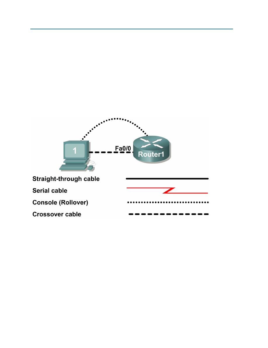
CCNA Exploration
Network Fundamentals:
Configuring and Testing Your Network
Lab 11.5.1 Basic Cisco Device Configuration
All contents are Copyright © 1992–2007 Cisco Systems, Inc. All rights reserved. This document is Cisco Public Information.
Page 8 of 20
Issue the command exit. What is the router prompt? What is the mode?
Router1(config-line)#
exit
___________________________________________________________________________________
___________________________________________________________________________________
Issue the command end. What is the router prompt? What is the mode?
___________________________________________________________________________________
___________________________________________________________________________________
Task 3: Configure Cisco Router Interfaces.
All cabled interfaces should contain documentation about the connection. On newer Cisco IOS versions,
the maximum description is 240 characters.
Figure 2. Physical lab topology.
Figure 2 shows a network topology where a host computer is connected to Router1, interface Fa0/0.
Write down your subnet number and mask: ________________________________________________
The first IP address will be used to configure the host computer LAN. Write down the first IP Address:
___________________________________________________________________________________
The last IP address will be used to configure the router fa0/0 interface. Write down the last IP Address:
___________________________________________________________________________________
Step 1: Configure the router fa0/0 interface.
Write a short description for the connections on Router1:
Fa0/0 ->
___________________________________________________________________________________

CCNA Exploration
Network Fundamentals:
Configuring and Testing Your Network
Lab 11.5.1 Basic Cisco Device Configuration
All contents are Copyright © 1992–2007 Cisco Systems, Inc. All rights reserved. This document is Cisco Public Information.
Page 9 of 20
Apply the description on the router interface with the interface configuration command, description:
Router1(config)#
interface fa0/0
Router1(config-if)#
description Connection to Host1 with crossover cable
Router1(config-if)#
ip address address mask
Router1(config-if)#
no shutdown
Router1(config-if)#
end
Router1#
Look for the interface to become active:
*Mar 24 19:58:59.602: %LINEPROTO-5-UPDOWN: Line protocol on Interface
FastEthernet0/0, changed state to up
Step 2: Configure the router Fa0/1 interface.
Write a short description for the connections on Router1:
Fa0/1 ->
___________________________________________________________________________________
Apply the description on the router interface with the interface configuration command, description:
Router1(config)#
interface fa0/1
Router1(config-if)#
description Connection to switch with straight-through
cable
Router1(config-if)#
ip address address mask
Router1(config-if)#
no shutdown
Router1(config-if)#
end
Router1#
Look for the interface to become active:
*Mar 24 19:58:59.602: %LINEPROTO-5-UPDOWN: Line protocol on Interface
FastEthernet0/1, changed state to up
Step 3: Configure the host computer.
Configure the host computer for LAN connectivity. Recall that the LAN configuration window is accessed
through Start | Control Panel | Network Connections. Right-click on the LAN icon, and select Properties.
Highlight the Internet Protocol field, and select Properties. Fill in the following fields:
IP Address: The first host address __________________________
Subnet Mask: The subnet mask ____________________________
Default Gateway: Router’s IP Address _______________________
Click OK, and then Close. Open a terminal window, and verify network settings with the ipconfig
command.
Step 4: Verify network connectivity.
Use the ping command to verify network connectivity with the router. If ping replies are not successful
troubleshoot the connection:
What Cisco IOS command can be used to verify the interface status? __________________________
What Windows command can be used to verify host computer configuration? _____________________

CCNA Exploration
Network Fundamentals:
Configuring and Testing Your Network
Lab 11.5.1 Basic Cisco Device Configuration
All contents are Copyright © 1992–2007 Cisco Systems, Inc. All rights reserved. This document is Cisco Public Information. Page 10 of 20
What is the correct LAN cable between host1 and Router1? _______________________________
Task 4: Save the Router Configuration File.
Cisco IOS refers to RAM configuration storage as running-configuration, and NVRAM configuration
storage as startup-configuration. For configurations to survive rebooting or power restarts, the RAM
configuration must be copied into non-volatile RAM (NVRAM). This does not occur automatically, NVRAM
must be manually updated after any changes are made.
Step 1: Compare router RAM and NVRAM configurations.
Use the Cisco IOS show command to view RAM and NVRAM configurations. The configuration is
displayed one screen at a time. A line containing “ -- more -- “ indicates that there is additional
information to display. The following list describes acceptable key responses:
Key
Description
<SPACE>
Display the next page.
<RETURN>
Display the next line.
Q
Quit
<CTRL> c
Quit
Write down one possible shortcut command that will display the contents of NVRAM.
Display the contents of NVRAM. If the output of NVRAM is missing, it is because there is no saved
configuration.:
Router1#
show startup-config
startup-config is not present
Router1#
Display the contents of RAM.
Router1#show running-config
Use the output to answer the following questions:
How large is the configuration file? ____________________
What is the enable secret password? ________________________
Does your MOTD banner contain the information you entered earlier? __________________________
Do your interface descriptions contain the information you entered earlier? ____________________
Write down one possible shortcut command that will display the contents of RAM. _________________
Step 2: Save RAM configuration to NVRAM.
For a configuration to be used the next time the router is powered on or reloaded, it must be manually
saved in NVRAM. Save the RAM configuration to NVRAM:
Router1#
copy running-config startup-config
Destination filename [startup-config]? <ENTER>
Building configuration...
[OK]

CCNA Exploration
Network Fundamentals:
Configuring and Testing Your Network
Lab 11.5.1 Basic Cisco Device Configuration
All contents are Copyright © 1992–2007 Cisco Systems, Inc. All rights reserved. This document is Cisco Public Information. Page 11 of 20
Router1#
Write down one possible shortcut command that will copy the RAM configuration to NVRAM.
____________________________
Review the contents of NVRAM, and verify that the configuration is the same as the configuration in RAM.
Task 5: Configure a Cisco Switch.
Cisco IOS switch configuration is (thankfully) similar to configuring a Cisco IOS router. The benefit of
learning IOS commands is that they are similar to many different devices and IOS versions.
Step 1: Connect the host to the switch.
Move the console, or rollover, cable to the console port on the switch. Ensure power has been applied to
the switch. In Hyperterminal, press Enter until the switch responds.
Step 2. Configure global configuration hostname setting.
Appendix 2 shows a typical default switch configuration. Depending on router model and IOS version,
your configuration may look slightly different. However, there should be no configured passwords. If your
router does not have a default configuration, ask the instructor to remove the configuration.
From the user exec mode, enter global configuration mode:
Switch>
en
Switch#
config t
Switch(config)#
Set the device hostname to Switch1.
Switch(config)#
hostname Switch1
Switch1(config)#
Step 3: Configure the MOTD banner.
Create a suitable MOTD banner. Only system administrators of the ABC company are authorized access,
unauthorized access will be prosecuted, and all connection information will be logged.
Configure the MOTD banner. The MOTD banner is displayed on all connections before the login prompt.
Use the terminating character on a blank line to end the MOTD entry. For assistance, review the similar
step for configuring a router MOTD banner.
Switch1(config)#
banner motd %
Step 4: Configure the privileged exec password.
Set the privileged exec password to cisco.
Switch1(config)#
enable secret cisco
Switch1(config)#
Step 5: Configure the console password.
Set the console access password to class.
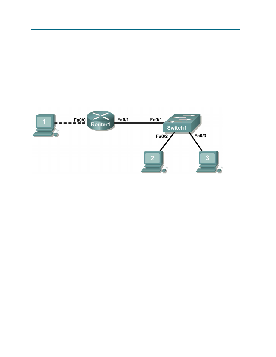
CCNA Exploration
Network Fundamentals:
Configuring and Testing Your Network
Lab 11.5.1 Basic Cisco Device Configuration
All contents are Copyright © 1992–2007 Cisco Systems, Inc. All rights reserved. This document is Cisco Public Information. Page 12 of 20
Switch1(config)#
line console 0
Switch1(config-line)#
password class
Switch1(config-line)#
login
Step 6: Configure the virtual line password.
Set the virtual line access password to class. There are 16 virtual lines that can be configured on a
Cisco IOS switch, 0 through 15.
Switch1(config-line)#
line vty 0 15
Switch1(config-line)#
password class
Switch1(config-line)#
login
Figure 3. Network topology.
Step 7: Configure the interface description.
Figure 3 shows a network topology where Router1 is connected to Switch1, interface Fa0/1. Switch1
interface Fa0/2 is connected to host computer 2, and interface Fa0/3 is connected to host computer 3.

CCNA Exploration
Network Fundamentals:
Configuring and Testing Your Network
Lab 11.5.1 Basic Cisco Device Configuration
All contents are Copyright © 1992–2007 Cisco Systems, Inc. All rights reserved. This document is Cisco Public Information. Page 13 of 20
Write a short description for the connections on Switch1:
Router1 Interface
Description
Fa0/1
Fa0/2
Fa0/3
Apply the descriptions on the switch interface with the interface configuration command, description:
Switch1(config)#
interface fa0/1
Switch1(config-if)#
description Connection to Router1
Switch1(config)#
interface fa0/2
Switch1(config-if)#
description Connection to host computer 2
Switch1(config)#
interface fa0/3
Switch1(config-if)#
description Connection to host computer 3
Switch1(config-if)#
end
Switch1#
Step 7: Save RAM configuration to NVRAM.
For a configuration to be used the next time the switch is powered on or reloaded, it must be manually
saved in NVRAM. Save the RAM configuration to NVRAM:
Switch1#
copy run start
Destination filename [startup-config]? <ENTER>
Building configuration...
[OK]
Switch1#
Review the contents of NVRAM, and verify that the configuration is the same as the configuration in RAM.
Task 6: Reflection
The more you practice the commands, the faster you will become in configuring a Cisco IOS router and
switch. It is perfectly acceptable to use notes at first to help configure a device, but a professional network
engineer does not need a ‘cheat sheet’ to perform common configuration tasks. The following table lists
commands covered in this lab:
Purpose
Command
Enter the global configuration mode. configure terminal
Example:
Router>
enable
Router# configure terminal
Router(config)#
Specify the name for the router.
hostname name
Example:
Router(config)#
hostname Router1
Router(config)#
Specify an encrypted password to
prevent unauthorized access to the
privileged exec mode.
enable secret password
Example:
Router(config)#
enable secret cisco
Router(config)#
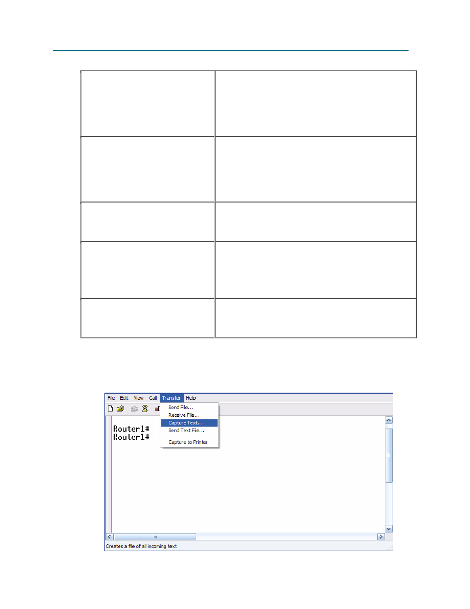
CCNA Exploration
Network Fundamentals:
Configuring and Testing Your Network
Lab 11.5.1 Basic Cisco Device Configuration
All contents are Copyright © 1992–2007 Cisco Systems, Inc. All rights reserved. This document is Cisco Public Information. Page 14 of 20
Specify a password to prevent
unauthorized access to the console.
password password
login
Example:
Router(config)#
line con 0
Router(config-line)#
password class
Router(config-line)#
login
Router(config)#
Specify a password to prevent
unauthorized telnet access.
Router vty lines: 0 4
Switch vty lines: 0 15
password password
login
Example:
Router(config)#
line vty 0 4
Router(config-line)#
password class
Router(config-line)#
login
Router(config-line)#
Configure the MOTD banner.
Banner motd %
Example:
Router(config)#
banner motd %
Router(config)#
Configure an interface.
Router- interface is OFF by default
Switch- interface is ON by default
Example:
Router(config)#
interface fa0/0
Router(config-if)#
description description
Router(config-if)#
ip address address mask
Router(config-if)#
no shutdown
Router(config-if)#
Save the configuration to NVRAM.
copy running-config startup-config
Example:
Router#
copy running-config startup-config
Router#
Task 7: Challenge
It is often necessary, and always handy, to save the configuration file to an off-line text file. One way to
save the configuration file is to use HyperTerminal Transfer menu option Capture.

CCNA Exploration
Network Fundamentals:
Configuring and Testing Your Network
Lab 11.5.1 Basic Cisco Device Configuration
All contents are Copyright © 1992–2007 Cisco Systems, Inc. All rights reserved. This document is Cisco Public Information. Page 15 of 20
Figure 2. Hyperterminal Capture menu.
Refer to Figure 2. All communication between the host computer and router are saved to a file. The file
can be edited, and saved. The file can also be edited, copied, and pasted into a router:
To start a capture, select Hyperterminal menu option Transfer | Capture Text. Enter a path and file name,
and select Start.
Issue the privileged exec command show running-config, and press the <SPACE> key until all of
the configuration has been displayed.
Stop the capture. Select menu option Transfer | Capture Text | Stop.
Open the text file and review the contents. Remove any lines that are not configuration commands, such
as the more prompt. Manually correct any lines that were scrambled or occupy the same line. After
checking the configuration file, highlight the lines and select Notepad menu Edit | Copy. This places the
configuration in host computer memory.
To load the configuration file, it is ALWAYS best practice to begin with a clean RAM configuration.
Otherwise, stale configuration commands may survive a paste action and have unintended
consequences (also known as the Law of Unintended Consequences):
Erase the NVRAM configuration file:
Router1#
erase start
Erasing the nvram filesystem will remove all configuration files! Continue?
[confirm]
<ENTER>
[OK]
Erase of nvram: complete
Reload the router:
Router1#
reload
Proceed with reload? [confirm]
<ENTER>
When the router reboots, enter the global configuration mode:
Router>
en
Router#
config t
Router(config)#
Using the mouse, right-click inside the Hyperterminal window and select Paste To Host. The configuration
will be loaded, very quickly, to the router. Watch closely for error messages, each message must be
investigated and corrected.
Verify the configuration, and save to NVRAM.

CCNA Exploration
Network Fundamentals:
Configuring and Testing Your Network
Lab 11.5.1 Basic Cisco Device Configuration
All contents are Copyright © 1992–2007 Cisco Systems, Inc. All rights reserved. This document is Cisco Public Information. Page 16 of 20
Task 6: Cleanup
Before turning off power to the router and switch, remove the NVRAM configuration file from each device
with the privileged exec command erase startup-config.
Delete any configuration files saved on the host computers.
Unless directed otherwise by the instructor, restore host computer network connectivity, then turn off
power to the host computers. Remove anything that was brought into the lab, and leave the room ready
for the next class.

CCNA Exploration
Network Fundamentals:
Configuring and Testing Your Network
Lab 11.5.1 Basic Cisco Device Configuration
All contents are Copyright © 1992–2007 Cisco Systems, Inc. All rights reserved. This document is Cisco Public Information. Page 17 of 20
Appendix 1- default Cisco IOS router configuration
Current configuration : 824 bytes
!
version 12.4
service timestamps debug datetime msec
service timestamps log datetime msec
no service password-encryption
!
hostname Router
!
boot-start-marker
boot-end-marker
!
no aaa new-model
ip cef
!
interface FastEthernet0/0
no ip address
shutdown
duplex auto
speed auto
!
interface FastEthernet0/1
no ip address
shutdown
duplex auto
speed auto
!
interface Serial0/1/0
no ip address
shutdown
no fair-queue
!
interface Serial0/1/1
no ip address
shutdown
clock rate 2000000
!
interface Vlan1
no ip address
!
ip http server
no ip http secure-server
!
control-plane
!
line con 0
line aux 0
line vty 0 4
login
!
scheduler allocate 20000 1000
end

CCNA Exploration
Network Fundamentals:
Configuring and Testing Your Network
Lab 11.5.1 Basic Cisco Device Configuration
All contents are Copyright © 1992–2007 Cisco Systems, Inc. All rights reserved. This document is Cisco Public Information. Page 18 of 20
Appendix 2- default Cisco IOS switch configuration
Current configuration : 1519 bytes
!
version 12.1
no service pad
service timestamps debug uptime
service timestamps log uptime
no service password-encryption
!
hostname Switch
!
!
ip subnet-zero
!
!
spanning-tree mode pvst
no spanning-tree optimize bpdu transmission
spanning-tree extend system-id
!
!
interface FastEthernet0/1
no ip address
!
interface FastEthernet0/2
no ip address
!
interface FastEthernet0/3
no ip address
!
interface FastEthernet0/4
no ip address
!
interface FastEthernet0/5
no ip address
!
interface FastEthernet0/6
no ip address
!
interface FastEthernet0/7
no ip address
!
interface FastEthernet0/8
no ip address
!
interface FastEthernet0/9
no ip address
!
interface FastEthernet0/10
no ip address
!
interface FastEthernet0/11
no ip address
!
interface FastEthernet0/12

CCNA Exploration
Network Fundamentals:
Configuring and Testing Your Network
Lab 11.5.1 Basic Cisco Device Configuration
All contents are Copyright © 1992–2007 Cisco Systems, Inc. All rights reserved. This document is Cisco Public Information. Page 19 of 20
no ip address
!
interface FastEthernet0/13
no ip address
!
interface FastEthernet0/14
no ip address
!
interface FastEthernet0/15
no ip address
!
interface FastEthernet0/16
no ip address
!
interface FastEthernet0/17
no ip address
!
interface FastEthernet0/18
no ip address
!
interface FastEthernet0/19
no ip address
!
interface FastEthernet0/20
no ip address
!
interface FastEthernet0/21
no ip address
!
interface FastEthernet0/22
no ip address
!
interface FastEthernet0/23
no ip address
!
interface FastEthernet0/24
no ip address
!
interface GigabitEthernet0/1
no ip address
!
interface GigabitEthernet0/2
no ip address
!
interface Vlan1
no ip address
no ip route-cache
shutdown
!
ip http server
!
!
line con 0
line vty 5 15
!

CCNA Exploration
Network Fundamentals:
Configuring and Testing Your Network
Lab 11.5.1 Basic Cisco Device Configuration
All contents are Copyright © 1992–2007 Cisco Systems, Inc. All rights reserved. This document is Cisco Public Information. Page 20 of 20
end
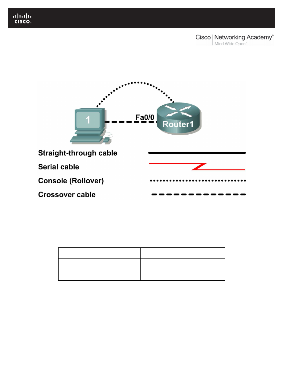
All contents are Copyright © 1992–2007 Cisco Systems, Inc. All rights reserved. This document is Cisco Public Information.
Page 1 of 9
Lab 11.5.2: Managing Device Configuration
Topology Diagram
Learning Objectives
•
Configure network connectivity.
•
Use TFTP to save and restore a Cisco IOS configuration.
Background
Hardware
Qty
Description
Cisco Router
1
Part of CCNA Lab bundle.
Computer (host)
1
Lab computer.
Console (rollover) cable
1
Connects computer host 1 to Router
console port.
Crossover cable
1
Connects host1 NIC to Router1 Fa0/1
Table 1. Equipment and hardware required for this lab.
Gather the necessary equipment and cables. To configure the lab, make sure the equipment listed in
Table 1 is available.
The host computer will be used as a TFTP server. This lab requires the use of SolarWinds TFTP server
software. SolarWinds is a free TFTP application for Windows.

CCNA Exploration
Network Fundamentals:
Configuring and Testing Your Network
Lab 11.5.2 Managing Device Configuration
All contents are Copyright © 1992–2007 Cisco Systems, Inc. All rights reserved. This document is Cisco Public Information.
Page 2 of 9
Scenario
In this lab, students will configure common settings on a Cisco Router, save the configuration to a TFTP
server, then restore the configuration from a TFTP server.
Given an IP address of 10.250.250.0/24, and 6 bits used for subnets. Use the LAST valid subnet.
Host1 should use the FIRST valid host address, and Router1 should use the LAST valid host address:
IP Address: 10.250.250.0
Subnet mask:
Subnet
First host address Last host address Broadcast
Task 1: Configure Network Connectivity.
Step 1: Physically connect devices.
Refer to the Topology Diagram. Connect the console, or rollover, cable to the console port on the router
and the other cable end to the host computer with a DB-9 or DB-25 adapter to the COM 1 port. Ensure
power has been applied to both the host computer and router.
Step 2: Logically connect devices.
Using the IP address information from the scenario, configure the host1 computer.
Step 3: Connect host computer to router through HyperTerminal.
From the Widows taskbar, start the HyperTerminal program by clicking on Start | Programs | Accessories
| Communications | Hyper Terminal.
When the HyperTerminal session window opens, press the Enter key until there is a response from the
router.
Step 4: Configure Router1.
Configure Router1. Configuration tasks for Router1 include the following:
Task- refer to Appendix 1 for help with commands
Specify Router name- Router1
Specify an encrypted privileged exec password- cisco
Specify a console access password- class
Specify a telnet access password- class
Configure the MOTD banner.
Configure Router1 interface Fa0/0- set the description
set the Layer 3 address
issue no shutdown
NOTE **DO NOT SAVE THE CONFIGURATION IN NVRAM.
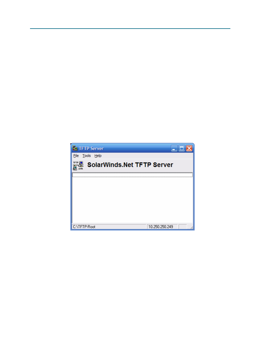
CCNA Exploration
Network Fundamentals:
Configuring and Testing Your Network
Lab 11.5.2 Managing Device Configuration
All contents are Copyright © 1992–2007 Cisco Systems, Inc. All rights reserved. This document is Cisco Public Information.
Page 3 of 9
Step 5: Verify connectivity.
Verify connectivity between host1 and Router1:
Router1#
ping 10.250.250.249
Type escape sequence to abort.
Sending 5, 100-byte ICMP Echos to 10.250.250.249, timeout is 2 seconds:
.!!!!
Success rate is 80 percent (4/5), round-trip min/avg/max = 1/1/1 ms
Router1#
Task 2: Use TFTP to Save and Restore a Cisco IOS Configuration.
Step 1: Install SolarWinds TFTP application.
Double click on the SolarWinds TFTP application to begin installation. Select Next. Agree to the license
agreement, and accept default settings. After SolarWinds has finished installation, click on Finish.
Step 2: Start TFTP server.
Figure 2. TFTP Server window.
Start the TFTP server by selecting Start | Programs | SolarWinds Free Tools | TFTP Server. Figure 2
shows an active TFTP Server window.
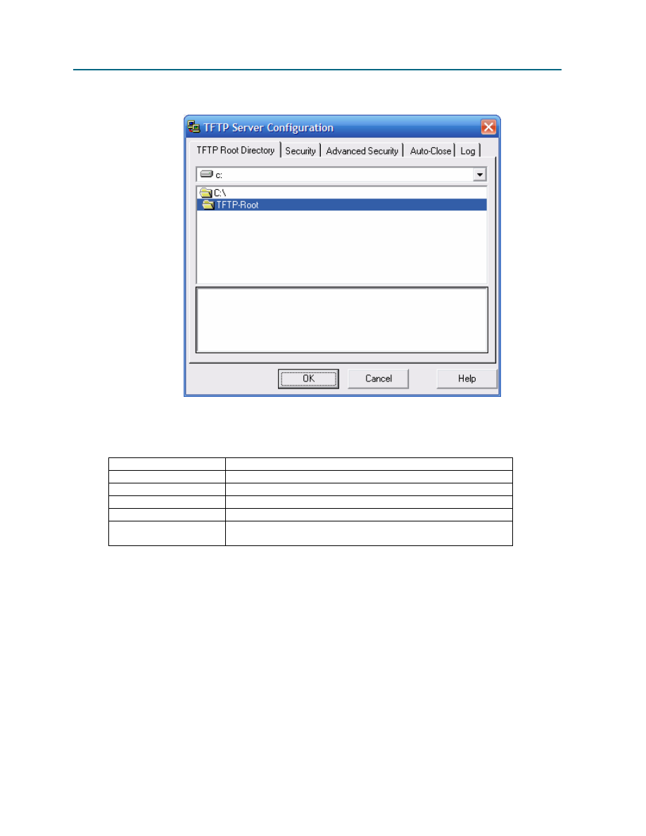
CCNA Exploration
Network Fundamentals:
Configuring and Testing Your Network
Lab 11.5.2 Managing Device Configuration
All contents are Copyright © 1992–2007 Cisco Systems, Inc. All rights reserved. This document is Cisco Public Information.
Page 4 of 9
Step 3: Configure the TFTP server.
Figure 3. TFTP Server window.
To configure TFTP server, select menu option File | configure. Refer to Figure 3. Verify the following
settings:
Setting
Value
TFTP Root Directory:
TFTP-Root
Security
Transmit and Receive Files
Advanced Security
10.250.250.250 To 10.250.250.250
Auto-Close
Never
Log
Enable Log Requests to the Following File. Leave the
default file.
When finished, select OK.
Step 4. Save Router1 configuration to TFTP server.
From HyperTerminal, begin a TFTP upload to the TFTP server:
Router1#
copy running-config tftp:
Address or name of remote host []?
10.250.250.249
Destination filename [router1-confg]?
<ENTER>
!!
1081 bytes copied in 2.008 secs (538 bytes/sec)
Router1#

CCNA Exploration
Network Fundamentals:
Configuring and Testing Your Network
Lab 11.5.2 Managing Device Configuration
All contents are Copyright © 1992–2007 Cisco Systems, Inc. All rights reserved. This document is Cisco Public Information.
Page 5 of 9
Verify a successful upload transfer. Open Log file c:\Program Files\SolarWinds\Free Tools\TFTP-
Server.txt. Contents should be similar to the following:
3/25/2007 12:29 :Receiving router1-confg from (10.250.250.250)
3/25/2007 12:29 :Received router1-confg from (10.250.250.250), 1081 bytes
Verify the transferred file. Use Microsoft Word or Wordpad to examine the contents of file c:\TFTP-
Root\router1-confg. Contents should be similar to the following configuration:
!
version 12.4
service timestamps debug datetime msec
service timestamps log datetime msec
no service password-encryption
!
hostname Router1
!
boot-start-marker
boot-end-marker
!
enable secret 5 $1$D02B$AuX05n0HPT239yYRoQ0oE.
!
no aaa new-model
ip cef
!
interface FastEthernet0/0
description connection to host1
ip address 10.250.250.250 255.255.255.252
duplex auto
speed auto
!
interface FastEthernet0/1
no ip address
shutdown
duplex auto
speed auto
!
interface Serial0/1/0
no ip address
shutdown
no fair-queue
!
interface Serial0/1/1
no ip address
shutdown
clock rate 2000000
!
ip http server
no ip http secure-server
!
control-plane
!
banner motd
*** ABC COMPANY NETWORK DEVICE ****
*** Authorized access only *****

CCNA Exploration
Network Fundamentals:
Configuring and Testing Your Network
Lab 11.5.2 Managing Device Configuration
All contents are Copyright © 1992–2007 Cisco Systems, Inc. All rights reserved. This document is Cisco Public Information.
Page 6 of 9
*** Logging is enabled ****
!
line con 0
password class
login
line aux 0
line vty 0 4
password class
login
!
scheduler allocate 20000 1000
End
Step 5: Restore Router1 configuration from TFTP server.
Verify that NVRAM is clear, then reboot Router1:
Router1#
show startup-config
startup-config is not present
Router1#
reload
Proceed with reload? [confirm]
<ENTER>
Connectivity must be established with the TFTP server. Router1 fa0/0 must be configured with an IP
address, and the interface enabled:
Router>
enable
Router#
conf t
Enter configuration commands, one per line. End with CNTL/Z.
Router(config)#
interface fa0/0
Router(config-if)#
ip address 10.250.250.250 255.255.255.252
Router(config-if)#
no shutdown
Router(config-if)#
exit
*Mar 25 16:43:03.095: %SYS-5-CONFIG_I: Configured from console by console
*Mar 25 16:43:04.967: %LINEPROTO-5-UPDOWN: Line protocol on Interface
FastEthernet0/0, changed state to up
Configure the hostname of the router to TEST
Router(config-if)#
exit
Router(config)#
hostname TEST
Router(config-if)#end
TEST#
Verify connectivity with the ping command:
Router#
ping 10.250.250.249
Type escape sequence to abort.
Sending 5, 100-byte ICMP Echos to 10.250.250.249, timeout is 2 seconds:
.!!!!
Success rate is 80 percent(4/5), round-trip min/avg/max = 1/1/1ms
Router#

CCNA Exploration
Network Fundamentals:
Configuring and Testing Your Network
Lab 11.5.2 Managing Device Configuration
All contents are Copyright © 1992–2007 Cisco Systems, Inc. All rights reserved. This document is Cisco Public Information.
Page 7 of 9
Download Router1 configuration file from the TFTP server:
Router#
copy tftp startup-config
Address or name of remote host []?
10.250.250.249
Source filename []?
router1-confg
Destination filename [startup-config]?
<ENTER>
Accessing tftp://10.250.250.249/router1-confg...
Loading router1-confg from 10.250.250.249 (via FastEthernet0/0): !
[OK - 1081 bytes]
1081 bytes copied in 9.364 secs (115 bytes/sec)
Router1#
*Mar 25 16:55:26.375: %SYS-5-CONFIG_I: Configured from
tftp://10.250.250.249/router1-confg by console
Router1#
View the configuration in NVRAM to verify an accurate transfer. The configuration should be the same as
what was configured in Task 1, Step 4.
Reload the router select no at the prompt that says “Configuration has been modified”.
The previous the configuration should be restored and the router’s hostname should now be Router1.
Task 3: Reflection
TFTP is a fast, efficient way to save and load Cisco IOS configuration files.
Task 4: Challenge
Similar to uploading a configuration file, the IOS can also be stored off-line for future use. To discover the
IOS filename, issue the Cisco IOS command show version. The filename is highlighted, below:
Router1#
show version
Cisco IOS Software, 1841 Software (C1841-ADVIPSERVICESK9-M), Version
12.4(10b),
RELEASE SOFTWARE (fc3)
Technical Support: http://www.cisco.com/techsupport
Copyright (c) 1986-2007 by Cisco Systems, Inc.
Compiled Fri 19-Jan-07 15:15 by prod_rel_team
ROM: System Bootstrap, Version 12.4(13r)T, RELEASE SOFTWARE (fc1)
Router1 uptime is 17 minutes
System returned to ROM by reload at 16:47:54 UTC Sun Mar 25 2007
System image file is "flash:c1841-advipservicesk9-mz.124-10b.bin"
This product contains cryptographic features and is subject to United States
and local country laws governing import, export, transfer and use. Delivery
of Cisco cryptographic products does not imply third-party authority to
import, export, distribute or use encryption. Importers, exporters,
distributors and users are responsible for compliance with U.S. and local
country laws. By using this product you agree to comply with applicable laws
and regulations. If you are unable to comply with U.S. and local laws, return
this product immediately.

CCNA Exploration
Network Fundamentals:
Configuring and Testing Your Network
Lab 11.5.2 Managing Device Configuration
All contents are Copyright © 1992–2007 Cisco Systems, Inc. All rights reserved. This document is Cisco Public Information.
Page 8 of 9
A summary of U.S. laws governing Cisco cryptographic products may be found
at:
http://www.cisco.com/wwl/export/crypto/tool/stqrg.html
If you require further assistance please contact us by sending email to
export@cisco.com.
Cisco 1841 (revision 6.0) with 174080K/22528K bytes of memory.
Processor board ID FHK110918KJ
2 Serial(sync/async) interfaces
DRAM configuration is 64 bits wide with parity disabled.
191K bytes of NVRAM.
62720K bytes of ATA CompactFlash (Read/Write)
Configuration register is 0x2102
Router1#
The commands to upload the IOS are similar to uploading the configuration file:
Router1#
copy flash tftp
Source filename []? c1841-advipservicesk9-mz.124-10b.bin
Address or name of remote host []? 10.250.250.249
Destination filename [c1841-advipservicesk9-mz.124-10b.bin]?
!!!!!!!!!!!!!!!!!!!!!!!!!!!!!!!!!!!!!!!!!!!!!!!!!!!!!!!!!!!!!!!!!!!!!!!!!!!!!
!!!!!!!!!!!
22063220 bytes copied in 59.564 secs (370412 bytes/sec)
Router1#
Task 5: Cleanup
Before turning off power to the router, remove the NVRAM configuration file if it was loaded. Use the
privileged exec command erase startup-config.
Remove SolarWinds TFTP server from the host computer. Select Start | Control Panel. Open Add or
Remove Applications. Select SolarWinds, then Remove. Accept defaults.
Delete any configuration files saved on the host computers.
Unless directed otherwise by the instructor, restore host computer network connectivity, then turn off
power to the host computers. Remove anything that was brought into the lab, and leave the room ready
for the next class.

CCNA Exploration
Network Fundamentals:
Configuring and Testing Your Network
Lab 11.5.2 Managing Device Configuration
All contents are Copyright © 1992–2007 Cisco Systems, Inc. All rights reserved. This document is Cisco Public Information.
Page 9 of 9
Appendix 1
Purpose
Command
Enter the global configuration mode. configure terminal
Example:
Router>
enable
Router# configure terminal
Router(config)#
Specify the name for the router.
hostname name
Example:
Router(config)#
hostname Router1
Router(config)#
Specify an encrypted password to
prevent unauthorized access to the
privileged exec mode.
enable secret password
Example:
Router(config)#
enable secret cisco
Router(config)#
Specify a password to prevent
unauthorized access to the console.
password password
login
Example:
Router(config)#
line con 0
Router(config-line)#
password class
Router(config-line)#
login
Router(config)#
Specify a password to prevent
unauthorized telnet access.
Router vty lines: 0 4
Switch vty lines: 0 15
password password
login
Example:
Router(config)#
line vty 0 4
Router(config-line)#
password class
Router(config-line)#
login
Router(config-line)#
Configure the MOTD banner.
Banner motd %
Example:
Router(config)#
banner motd %
Router(config)#
Configure an interface.
Router- interface is OFF by default
Switch- interface is ON by default
Example:
Router(config)#
interface fa0/0
Router(config-if)#
description description
Router(config-if)#
ip address address mask
Router(config-if)#
no shutdown
Router(config-if)#
Save the configuration to NVRAM.
copy running-config startup-config
Example:
Router#
copy running-config startup-config
Router#
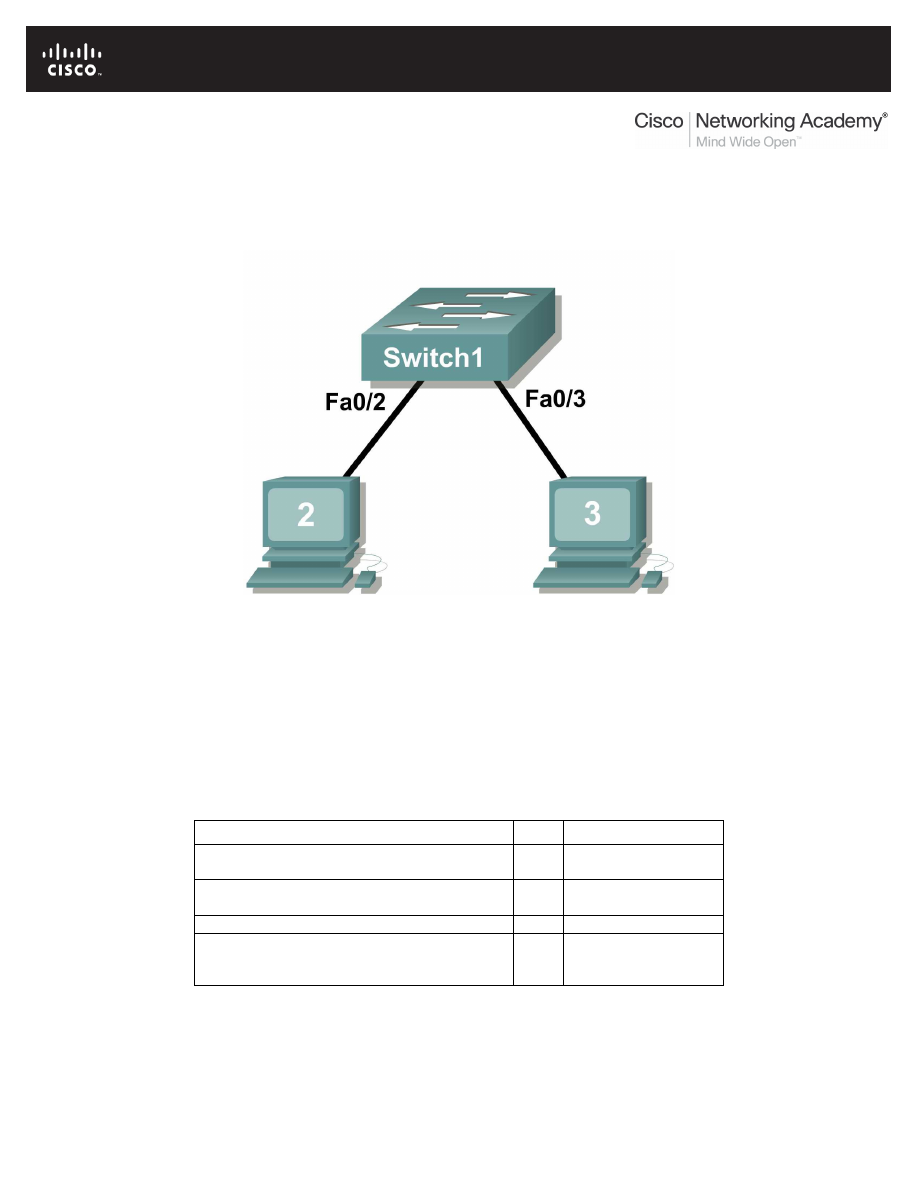
All contents are Copyright © 1992–2007 Cisco Systems, Inc. All rights reserved. This document is Cisco Public Information.
Page 1 of 8
Lab 11.5.3: Configure Host Computers for IP Networking
Topology Diagram
Learning Objectives
Upon completion of this lab, you will be able to:
•
Design the logical lab topology.
•
Configure the physical lab topology.
•
Configure the logical LAN topology.
•
Verify LAN connectivity.
Background
Hardware
Qty
Description
Cisco Router
1
Part of CCNA Lab
bundle
Cisco Switch
1
Part of CCNA Lab
bundle
*Computer (Host)
3
Lab computer
CAT-5 or better straight-through UTP cables
3
Connects Router1
and computers Host1
and Host2 to switch1
Table 1. Equipment and Hardware for this Lab
Gather the necessary equipment and cables. To configure the lab, make sure the equipment listed in
Table 1 is available.

CCNA Exploration
Network Fundamentals:
Configuring and Testing Your Network
Lab 11.5.3 Configure Host Computers for IP Networking
All contents are Copyright © 1992–2007 Cisco Systems, Inc. All rights reserved. This document is Cisco Public Information.
Page 2 of 8
Scenario
In this lab students will create a small network that requires connecting network devices and configuring
host computers for basic network connectivity. The Appendix is a reference for configuring the logical
network.
Task 1: Design the Logical Lab Topology.
1. Given an IP address of 192.168.254.0/24, and 5 bits used for subnets, fill in the following
information:
Maximum number of usable subnets (including the 0
th
subnet): __________
Number of usable Hosts per subnet: __________
IP Address: 192.168.254.0
Subnet mask:
#
Subnet
First Host address
Last Host address
Broadcast
0
1
2
3
4
5
6
7
8
9
10
11
12
13
14
15
16
17
18
19
20
21
22
23
24
25
26
27
28
29
30
2. Before proceeding, verify your addresses with the instructor. The instructor will assign one
subnetwork per student or team.
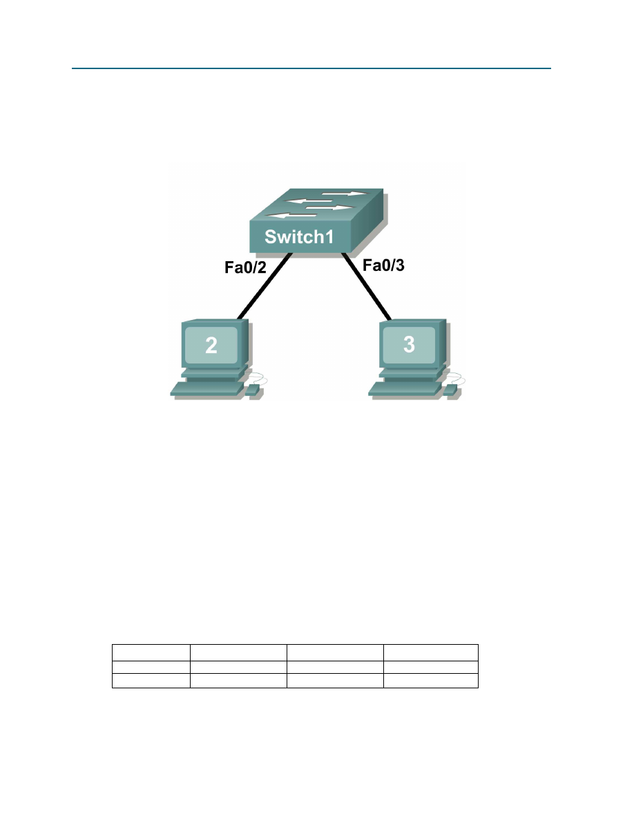
CCNA Exploration
Network Fundamentals:
Configuring and Testing Your Network
Lab 11.5.3 Configure Host Computers for IP Networking
All contents are Copyright © 1992–2007 Cisco Systems, Inc. All rights reserved. This document is Cisco Public Information.
Page 3 of 8
Task 2: Configure the Physical Lab Topology.
Step 1: Physically connect devices.
1. Cable the network devices as shown in Figure 1.
Figure 1. Cabling the Network
Is a crossover cable needed to connect Host computers to the switch? Why or why not?
_____________________________________________________________________________
_____________________________________________________________________________
If not already enabled, turn power on to all devices.
Step 2: Visually inspect network connections.
After cabling the network devices, take a moment to verify the connections. Attention to detail now will
minimize the time required to troubleshoot network connectivity issues later.
Task 3: Configure the Logical Topology.
Step 1: Document logical network settings.
1. Host computers will use the first two IP addresses in the subnetwork. Write down the IP address
information for each device:
Device
Subnetwork
IP address
Mask
Host1
Host2
Figure 2. Logical Topology
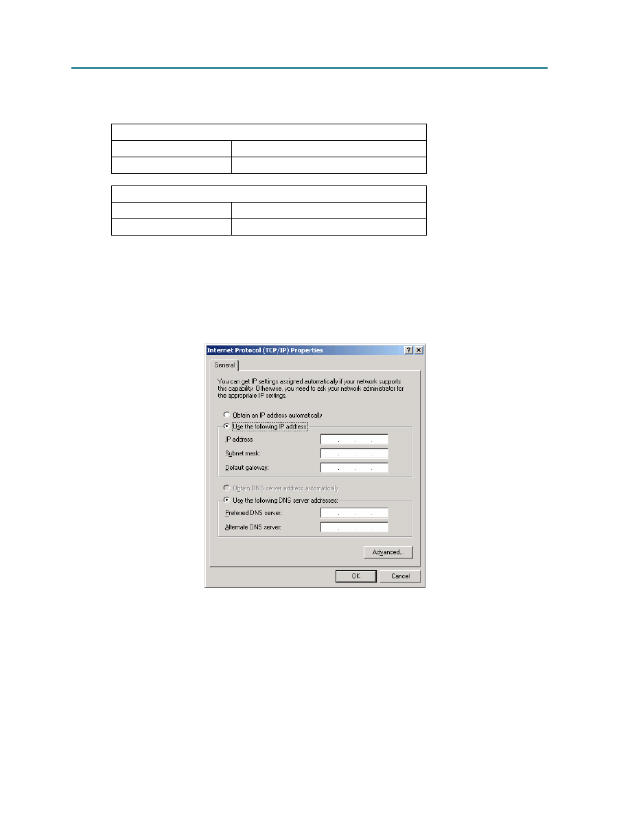
CCNA Exploration
Network Fundamentals:
Configuring and Testing Your Network
Lab 11.5.3 Configure Host Computers for IP Networking
All contents are Copyright © 1992–2007 Cisco Systems, Inc. All rights reserved. This document is Cisco Public Information.
Page 4 of 8
2. From the information given in Figure 2, write down the IP network addressing for each computer:
Host 1
IP Address
IP Mask
Host 2
IP Address
IP Mask
Step 2: Configure Host1 computer.
1. On Computer1, click Start > Control Panel > Network Connections. Right-click the LAN icon,
and choose Properties. On the General tab, select Internet Protocol (TCP/IP), and then click
the Properties button.
Figure 3. Host1 IP Address and Gateway Settings
2. Refer to Figure 3 for Host1 IP address and gateway settings.
3. When finished, click OK, then click Close. The computer may require a reboot for changes to be
effective.
4. Verify proper configuration of Host1 with the ipconfig /all command.

CCNA Exploration
Network Fundamentals:
Configuring and Testing Your Network
Lab 11.5.3 Configure Host Computers for IP Networking
All contents are Copyright © 1992–2007 Cisco Systems, Inc. All rights reserved. This document is Cisco Public Information.
Page 5 of 8
5. Record the output below:
Setting
Value
Ethernet device
Physical Address
IP Address
Subnet Mask
Default Gateway
Step 3: Configure Host2.
1. Repeat Step 2 for Host2, using IP address information from the table filled out in Step 1.
2. Verify proper configuration of Host1 with the ipconfig /all command.
3. Record the output below:
Setting
Value
Ethernet device
Physical Address
IP Address
Subnet Mask
Default Gateway
Task 4: Verify Network Connectivity.
Network connectivity can be verified with the Windows ping command.
1. Use the following table to methodically verify connectivity with each network device:
From
To
IP Address
Ping results
Host1
Host2
Host2
Host1
2. Take corrective action to establish connectivity if a test fails.
Note: If pings to host computers fail, temporarily disable the computer firewall and retest. To
disable a Windows firewall, click Start > Control Panel > Windows Firewall, choose Off, and
then click OK.
Task 5: Reflection
Review any physical or logical configuration problems encountered during this lab. Make sure you have a
thorough understanding of the procedures used to configure a Windows host computer.
Task 6: Challenge
Ask your instructor or another student to introduce one or two problems in your network when you aren’t
looking or are out of the lab room. Problems can be either physical (wrong UTP cable) or logical (wrong
IP address). To fix the problems:

CCNA Exploration
Network Fundamentals:
Configuring and Testing Your Network
Lab 11.5.3 Configure Host Computers for IP Networking
All contents are Copyright © 1992–2007 Cisco Systems, Inc. All rights reserved. This document is Cisco Public Information.
Page 6 of 8
1. Perform a good visual inspection. Look for green link lights on Switch1.
2. Use the table provided in Task 3, above, to identify failed connectivity. List the problems:
___________________________________________________________________________
___________________________________________________________________________
___________________________________________________________________________
___________________________________________________________________________
___________________________________________________________________________
3. Write down your proposed solution(s):
___________________________________________________________________________
___________________________________________________________________________
___________________________________________________________________________
___________________________________________________________________________
___________________________________________________________________________
4. Test your solution. If the solution fixed the problem, document the solution. If the solution did not
fix the problem, continue troubleshooting.
___________________________________________________________________________
___________________________________________________________________________
___________________________________________________________________________
___________________________________________________________________________
___________________________________________________________________________
Task 7: Clean Up
Unless directed otherwise by the instructor, restore host computer network connectivity, and then turn off
power to the host computers. Remove anything that was brought into the lab, and leave the room ready
for the next class.

CCNA Exploration
Network Fundamentals:
Configuring and Testing Your Network
Lab 11.5.3 Configure Host Computers for IP Networking
All contents are Copyright © 1992–2007 Cisco Systems, Inc. All rights reserved. This document is Cisco Public Information.
Page 7 of 8
Appendix
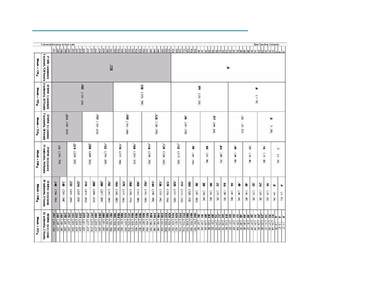
CCNA Exploration
Network Fundamentals:
Configuring and Testing Your Network
Lab 11.5.3 Configure Host Computers for IP Networking
All contents are Copyright © 1992–2007 Cisco Systems, Inc. All rights reserved. This document is Cisco Public Information.
Page 8 of 8
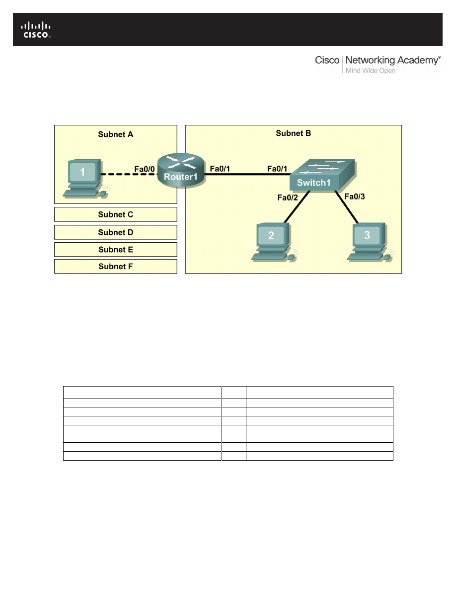
All contents are Copyright © 1992–2007 Cisco Systems, Inc. All rights reserved. This document is Cisco Public Information.
Page 1 of 11
Lab 11.5.4: Network Testing
Topology Diagram
Learning Objectives
Upon completion of this lab, you will be able to:
•
Design the logical lab topology.
•
Configure the physical lab topology.
•
Configure the logical LAN topology.
•
Verify LAN connectivity.
Background
Hardware
Qty
Description
Cisco Router
1
Part of CCNA Lab bundle
Cisco Switch
1
Part of CCNA Lab bundle
*Computer (Host)
3
Lab computer
CAT-5 or better straight-through UTP cables
3
Connects Router1, Host1, and Host2 to
switch1
CAT-5 crossover UTP cable
1
Connects Host 1 to Router1
Console (rollover) cable
1
Connects Host1 to Router1 console
Table 1. Equipment and Hardware for this Lab
Gather the necessary equipment and cables. To configure the lab, make sure the equipment listed in
Table 1 is available.
The Appendix contains Cisco IOS configuration syntax for this lab.

CCNA Exploration
Network Fundamentals:
Configuring and Testing Your Network
Lab 11.5.4 Network Testing
All contents are Copyright © 1992–2007 Cisco Systems, Inc. All rights reserved. This document is Cisco Public Information.
Page 2 of 11
Scenario
In this lab, you will create a small network that requires connecting network devices and configuring host
computers for basic network connectivity. SubnetA and SubnetB are subnets that are currently needed.
SubnetC, SubnetD, SubnetE, and SubnetF are anticipated subnets, not yet connected to the network.
The 0
th
subnet will be used.
Task 1: Design the Logical Lab Topology.
Given an IP address and mask of 172.20.0.0 / 24 (address / mask), design an IP addressing
scheme that satisfies the following requirements:
Subnet
Number of Hosts
SubnetA
As shown in topology diagram
SubnetB
Between 80 – 100
SubnetC
Between 40 – 52
SubnetD
Between 20 – 29
SubnetE
12
SubnetF
5
Note: Always start with the subnet with the largest number of hosts and work your way down.
Therefore, you should start with SubnetB and finish with SubnetA.
Step 1: Design SubnetB address block.
Begin the logical network design by satisfying the requirement of SubnetB, which requires the largest
block of IP addresses. Using binary numbers to create your subnet chart, pick the first address block that
will support SubnetB.
1. Fill in the following table with IP address information for SubnetB:
Network
Address
Mask
First Host
Address
Last Host
Address
Broadcast
2. What is the bit mask? _________________________________________________________
Step 2: Design SubnetC address block.
Satisfy the requirement of SubnetC, the next largest IP address block. Using binary numbers to create
your subnet chart, pick the next available address block that will support SubnetC.
1. Fill in the following table with IP address information for SubnetC:
Network
Address
Mask
First Host
Address
Last Host
Address
Broadcast
2. What is the bit mask? _________________________________________________________
Step 3: Design SubnetD address block.
Satisfy the requirement of SubnetD, the next largest IP address block. Using binary numbers to create
your subnet chart, pick the next available address block that will support SubnetD.

CCNA Exploration
Network Fundamentals:
Configuring and Testing Your Network
Lab 11.5.4 Network Testing
All contents are Copyright © 1992–2007 Cisco Systems, Inc. All rights reserved. This document is Cisco Public Information.
Page 3 of 11
1. Fill in the following table with IP address information for SubnetD:
Network
Address
Mask
First Host
Address
Last Host
Address
Broadcast
2. What is the bit mask? _________________________________________________________
Step 4: Design SubnetE address block.
Satisfy the requirement of SubnetE, the next largest IP address block. Using binary numbers to create
your subnet chart, pick the next available address block that will support SubnetE.
1. Fill in the following table with IP address information for SubnetE:
Network
Address
Mask
First Host
Address
Last Host
Address
Broadcast
2. What is the bit mask? _________________________________________________________
Step 5: Design SubnetF address block.
Satisfy the requirement of SubnetF, the next largest IP address block. Using binary numbers to create
your subnet chart, pick the next available address block that will support SubnetF.
1. Fill in the following table with IP address information for SubnetF:
Network
Address
Mask
First Host
Address
Last Host
Address
Broadcast
2. What is the bit mask? _________________________________________________________
Step 6: Design SubnetA address block.
Satisfy the requirement of SubnetA, the smallest IP address block. Using binary numbers to create your
subnet chart, pick the next available address block that will support SubnetA.
1. Fill in the following table with IP address information for SubnetA:
Network
Address
Mask
First Host
Address
Last Host
Address
Broadcast
2. What is the bit mask? _________________________________________________________
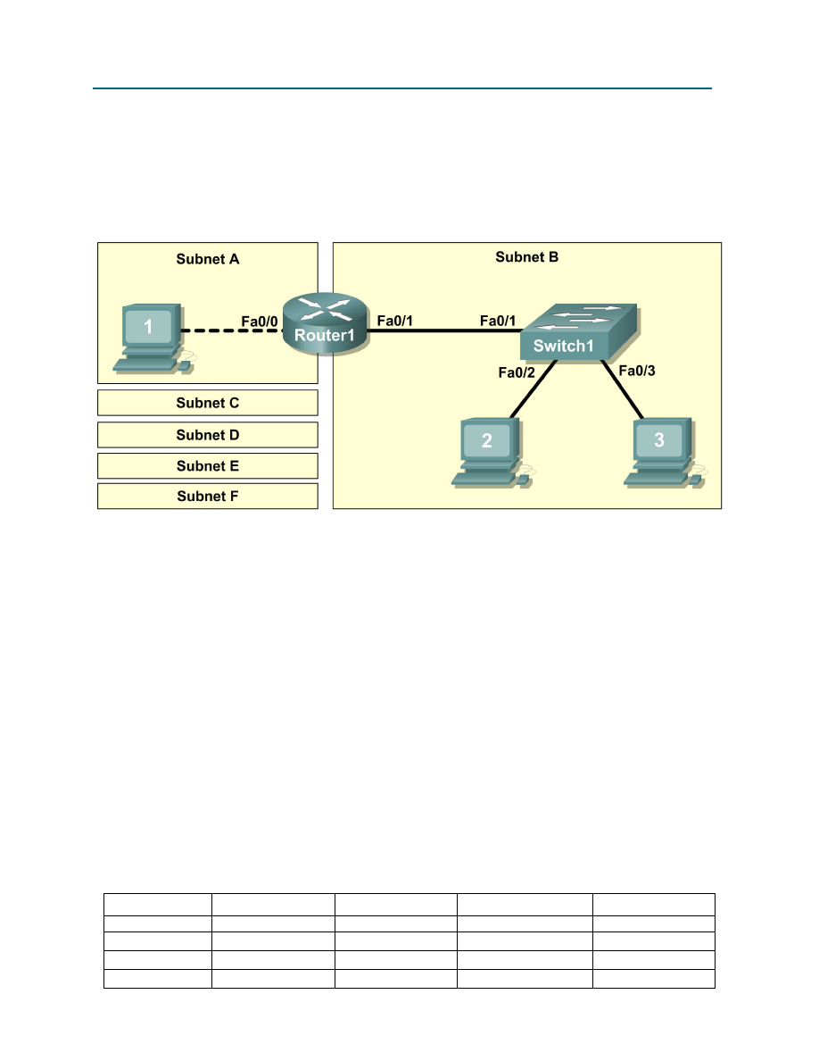
CCNA Exploration
Network Fundamentals:
Configuring and Testing Your Network
Lab 11.5.4 Network Testing
All contents are Copyright © 1992–2007 Cisco Systems, Inc. All rights reserved. This document is Cisco Public Information.
Page 4 of 11
Task 2: Configure the Physical Lab Topology.
Step 1: Physically connect lab devices.
1. Cable the network devices as shown in Figure 1. Pay special attention to the crossover cable
required between Host1 and Router1.
Figure 1. Cabling the Network
2. If not already enabled, turn power on to all devices.
Step 2: Visually inspect network connections.
After cabling the network devices, take a moment to verify the connections. Attention to detail now will
minimize the time required to troubleshoot Layer 1 connectivity issues later.
Task 3: Configure the Logical Topology.
Step 1: Document logical network settings.
On SubnetA, Host1 will use the first IP address in the subnet. Router1, interface Fa0/0, will use the last
host address. On SubnetB, host computers will use the first and second IP addresses in the subnet,
respectively. Router1, interface Fa0/1, will use the last network host address.
To properly route Layer 2 frames between LAN devices, Switch1 does not require Layer 3 configuration.
The IP address assigned to Switch 1, interface VLAN 1, is used to establish Layer 3 connectivity between
external devices and the switch. Without an IP address, upper-layer protocols such as TELNET and
HTTP will not work. The default gateway address permits the switch to respond to protocol requests from
devices on distant networks. For example, the IP gateway address extends Layer 3 connectivity beyond
Subnet B. Switch1 will use the next-to-last host address.
Write down the IP address information for each device:
Device
Subnet
IP Address
Mask
Gateway
Host1
Router1-Fa0/0
Host2
Host3

CCNA Exploration
Network Fundamentals:
Configuring and Testing Your Network
Lab 11.5.4 Network Testing
All contents are Copyright © 1992–2007 Cisco Systems, Inc. All rights reserved. This document is Cisco Public Information.
Page 5 of 11
Switch1
Router1-Fa0/1
Step 2: Configure host computers.
1. On each computer, in turn, click Start > Control Panel > Network Connections. Right-click the
LAN icon, and choose Properties. On the General tab, select Internet Protocol (TCP/IP), and
then click the, Properties button.
2. Verify that the Host1 Layer 3 IP address is on a different subnet than Host2 and Host3. Configure
each host computer using the IP address information recorded in Step 1.
3. Verify proper configuration of each host computer with the ipconfig command and fill in the
following table:
Device
IP Address
Mask
Default Gateway
Host1
Host2
Host3
Step 3: Configure Router1.
1. From the Windows taskbar, start the HyperTerminal program by clicking Start > Programs >
Accessories > Communications > HyperTerminal. Configure HyperTerminal for access to
Router1. Configuration for Router1 includes the following tasks:
Tasks
(Refer to the Appendix for help with commands)
Specify Router name: Router1
Specify an encrypted privileged EXEC password: cisco
Specify a console access password: class
Specify a telnet access password: class
Configure the MOTD banner
Configure Router1 interface Fa0/0:
•
Set the description
•
Set the Layer 3 address
•
Issue no shutdown
Configure Router1 interface Fa0/1:
•
Set the description
•
Set the Layer 3 address
•
Issue no shutdown
2. Save the configuration in NVRAM.
3. Display the contents of RAM:
4. Write the configuration specifications below:
Hostname: ________________________
Enable secret password: ________________________

CCNA Exploration
Network Fundamentals:
Configuring and Testing Your Network
Lab 11.5.4 Network Testing
All contents are Copyright © 1992–2007 Cisco Systems, Inc. All rights reserved. This document is Cisco Public Information.
Page 6 of 11
Console access password: ________________________
Telnet access password: ________________________
MOTD banner: ________________________
5. Display configuration information for interface Fa0/0: show interface Fa0/0
FastEthernet 0/0 status (up / down): ________________________
Line protocol: ________________________
MAC Address:
________________________
6. Display configuration information for interface Fa0/1: show interface Fa0/1
FastEthernet 0/0 status (up / down): ________________________
Line protocol: ________________________
MAC Address:
________________________
7. Display brief IP address information about each interface: show ip interface brief
Interface IP-Address OK? Method Status Protocol
FastEthernet0/0
FastEthernet0/1
8. Take corrective action with any problems, and retest.
Step 4: Configure Switch1.
1. Move the console cable from Router1 to Switch1.
2. Press Enter until a response is received.
3. Configuration for Switch1 includes the following tasks:
Tasks
(Refer to the Appendix for help with commands)
Specify Switch name- Switch1
Specify an encrypted privileged exec password- cisco
Specify a console access password- class
Specify a telnet access password- class
Configure the MOTD banner
Configure Switch1 interface Fa0/1: Set the description
Configure Switch1 interface Fa0/2: Set the description
Configure Switch1 interface Fa0/3: Set the description
Configure management VLAN 1 IP address:
•
Set the description
•
Set the Layer 3 address
•
Issue no shutdown
Configure default IP gateway address
4. Display the contents of RAM:

CCNA Exploration
Network Fundamentals:
Configuring and Testing Your Network
Lab 11.5.4 Network Testing
All contents are Copyright © 1992–2007 Cisco Systems, Inc. All rights reserved. This document is Cisco Public Information.
Page 7 of 11
5. Write the configuration specifications below:
Hostname: ________________________
Enable secret password: ________________________
Console access password: ________________________
Telnet access password: ________________________
MOTD banner: ________________________
Interface VLAN 1: ________________________
Default IP gateway address: ________________________
6. Display configuration information for interface VLAN 1: show interface vlan1
VLAN 1 status (up / down): ________________________
Line protocol: ________________________
Task 4: Verify Network Connectivity.
Step 1: Use the ping command to verify network connectivity.
Network connectivity can be verified with the ping command. It is very important that connectivity exists
throughout the network. Corrective action must be taken if there is a failure.
1. Use the following table to methodically verify connectivity with each network device:
From
To
IP Address
Ping results
Host1
LocalHost (127.0.0.1)
Host1
NIC IP address
Host1
Gateway (Router1, Fa0/0)
Host1
Router1, Fa0/1
Host1
Switch1
Host1
Host2
Host1
Host3
Host2
LocalHost (127.0.0.1)
Host2
NIC IP address
Host2
Host3
Host2
Switch1
Host2
Gateway (Router1, Fa0/1)
Host2
Router1, Fa0/0
Host2
Host1
Host3
LocalHost (127.0.0.1)
Host3
NIC IP address
Host3
Host2

CCNA Exploration
Network Fundamentals:
Configuring and Testing Your Network
Lab 11.5.4 Network Testing
All contents are Copyright © 1992–2007 Cisco Systems, Inc. All rights reserved. This document is Cisco Public Information.
Page 8 of 11
From
To
IP Address
Ping results
Host3
Switch1
Host3
Gateway (Router1, Fa0/1)
Host3
Router1, Fa0/0
Host3
Host1
2. Take corrective action to establish connectivity if a test fails.
Note: If pings to host computers fail, temporarily disable the computer firewall and retest. To
disable a Windows firewall, click Start > Control Panel > Windows Firewall, choose Off, and
then click OK.
Step 2: Use the tracert command to verify local connectivity.
1. From Host1, issue the tracert command to Host2 and Host3.
2. Record the results:
From Host1 to Host2: ________________________
From Host1 to Host3: ________________________
Step 3: Verify Layer 2 connectivity.
1. If not already connected, move the console cable from Router1 to Switch1.
2. Press the Enter key until there is a response from Switch1.
3. Issue the command show mac-address-table. This command will display static (CPU) and
dynamic, or learned, entries.
4. List the dynamic MAC addresses and corresponding switch ports:
MAC Address
Switch Port
5. Verify that there are three dynamically learned MAC addresses, one each from Fa0/1, Fa0/2, and
Fa0/3.
Task 5: Reflection
Review any physical or logical configuration problems encountered during this lab. Make sure you have a
thorough understanding of the procedures used to verify network connectivity.
Task 6: Challenge
Ask your instructor or another student to introduce one or two problems in your network when you aren’t
looking or are out of the lab room. Problems can be either physical (wrong UTP cable) or logical (wrong
IP address or gateway). To fix the problems:
1. Perform a good visual inspection. Look for green link lights on Switch1.
2. Use the table provided in Task 3, above, to identify failed connectivity. List the problems:
___________________________________________________________________________
___________________________________________________________________________

CCNA Exploration
Network Fundamentals:
Configuring and Testing Your Network
Lab 11.5.4 Network Testing
All contents are Copyright © 1992–2007 Cisco Systems, Inc. All rights reserved. This document is Cisco Public Information.
Page 9 of 11
___________________________________________________________________________
___________________________________________________________________________
___________________________________________________________________________
3. Write down your proposed solution(s):
___________________________________________________________________________
___________________________________________________________________________
___________________________________________________________________________
___________________________________________________________________________
___________________________________________________________________________
4. Test your solution. If the solution fixed the problem, document the solution. If the solution did not
fix the problem, continue troubleshooting.
___________________________________________________________________________
___________________________________________________________________________
___________________________________________________________________________
___________________________________________________________________________
___________________________________________________________________________
Task 7: Clean Up
Unless directed otherwise by the instructor, restore host computer network connectivity, and then turn off
power to the host computers.
Before turning off power to the router and switch, remove the NVRAM configuration file from each device
with the privileged exec command erase startup-config.
Carefully remove cables and return them neatly to their storage. Reconnect cables that were
disconnected for this lab.
Remove anything that was brought into the lab, and leave the room ready for the next class.

CCNA Exploration
Network Fundamentals:
Configuring and Testing Your Network
Lab 11.5.4 Network Testing
All contents are Copyright © 1992–2007 Cisco Systems, Inc. All rights reserved. This document is Cisco Public Information. Page 10 of 11
Appendix—List of Cisco IOS commands used in this lab
Purpose
Command
Enter the global configuration mode. configure terminal
Example:
Router>
enable
Router#
configure terminal
Router(config)#
Specify the name for the Cisco
device.
hostname name
Example:
Router(config)#
hostname Router1
Router(config)#
Specify an encrypted password to
prevent unauthorized access to the
privileged EXEC mode.
Enable secret password
Example:
Router(config)#
enable secret cisco
Router(config)#
Specify a password to prevent
unauthorized access to the console.
password password
login
Example:
Router(config)#
line con 0
Router(config-line)#
password class
Router(config-line)#
login
Router(config)#
Specify a password to prevent
unauthorized Telnet access.
Router vty lines: 0 4
Switch vty lines: 0 15
password password
login
Example:
Router(config)#
line vty 0 4
Router(config-line)#
password class
Router(config-line)#
login
Router(config-line)#
Configure the MOTD banner.
Banner motd %
Example:
Router(config)#
banner motd %
Router(config)#
Configure a Router interface.
Router interface is OFF by default
Example:
Router(config)#
interface Fa0/0
Router(config-if)#
description description
Router(config-if)#
ip address address mask
Router(config-if)#
no shutdown
Router(config-if)#
Switch interface is ON by default
(VLAN interface is OFF by default)
Example:
Switch(config)#
interface Fa0/0
Switch(config-if)#
description description
Switch(config)#
interface vlan1
Switch(config-if)#
ip address address mask
Switch(config-if)#
no shutdown
Switch(config-if)#
Switch- create a default IP gateway
Switch(config)#
ip default-gateway address
Save the configuration to NVRAM.
copy running-config startup-config
Example:

CCNA Exploration
Network Fundamentals:
Configuring and Testing Your Network
Lab 11.5.4 Network Testing
All contents are Copyright © 1992–2007 Cisco Systems, Inc. All rights reserved. This document is Cisco Public Information. Page 11 of 11
Router#
copy running-config startup-config
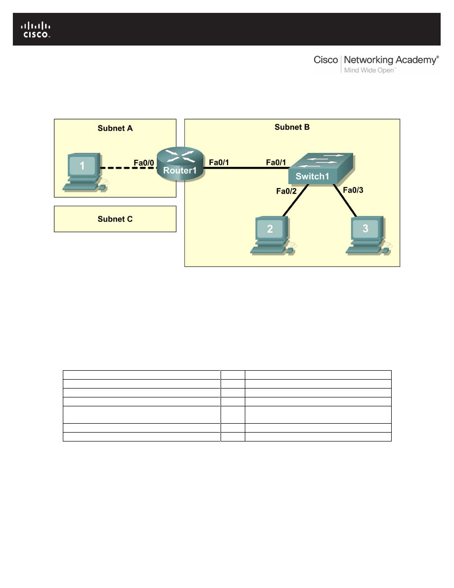
All contents are Copyright © 1992–2007 Cisco Systems, Inc. All rights reserved. This document is Cisco Public Information.
Page 1 of 12
Lab 11.5.5: Network Documentation with Utility Commands
Topology Diagram
Learning Objectives
•
Design the logical lab topology.
•
Configure the physical lab topology.
•
Design and configure the logical LAN topology.
•
Verify LAN connectivity.
•
Document the network.
Background
Hardware
Qty
Description
Cisco Router
1
Part of CCNA Lab bundle.
Cisco Switch
1
Part of CCNA Lab bundle.
*Computer (host)
3
Lab computer.
CAT-5 or better straight-through UTP cables
3
Connects Router1, Host1, and Host2 to
switch1.
CAT-5 crossover UTP cable
1
Connects host 1 to Router1
Console (rollover) cable
1
Connects Host1 to Router1 console
Table 1. Equipment and hardware for Eagle 1 lab.
Gather the necessary equipment and cables. To configure the lab, make sure the equipment listed in
Table 1 is available.
In this lab router and host output will be copied from the devices and into Notepad for use in network
documentation. Appendix1 contains tables that can be used to copy output into, or create your own
tables.

CCNA Exploration
Network Fundamentals:
Configuring and Testing Your Network
Lab 11.5.5 Network Documentation with Utility Commands
All contents are Copyright © 1992–2007 Cisco Systems, Inc. All rights reserved. This document is Cisco Public Information.
Page 2 of 12
Scenario
Network documentation is a very important tool for the organization. A well-documented network enables
network engineers to save significant time in troubleshooting and planning future growth.
In this lab students will create a small network that requires connecting network devices and configuring
Host computers for basic network connectivity. Subnet A and Subnet B are subnets that are currently
needed. Subnet C is an anticipated subnet, not yet connected to the network. The 0
th
subnet will be used.
Task 1: Configure the logical lab topology.
Given an IP address of 209.165.200.224 / 27 (address / mask), design an IP addressing
scheme that satisfies the following requirements:
Subnet
Number of Hosts
Subnet A
2
Subnet B
Between 2 - 6
Subnet C
Between 10 – 12
Step 1: Design Subnet C address block.
Begin the logical network design by satisfying the requirement for Subnet C, the largest IP address block.
Using binary numbers to create your subnet chart, pick the next available address block that will support
Subnet C.
Fill in the following table with IP address information for Subnet C:
Network Address
Mask
First Host address
Last Host address
Broadcast
What is the bit mask? ______________________
Step 2: Design Subnet B address block.
Satisfy the requirement of Subnet B, the next largest block of IP addresses. Using binary numbers to
create your subnet chart, pick the first address block that will support Subnet B.
Fill in the following table with IP address information for Subnet B:
Network Address
Mask
First Host address
Last Host address
Broadcast
What is the bit mask? _______________________
Step 3: Design Subnet A address block.
Satisfy the requirement of Subnet A, the smallest IP address block. Using binary numbers to create your
subnet chart, pick the next available address block that will support Subnet A.
Fill in the following table with IP address information for Subnet A:
Network Address
Mask
First Host address
Last Host address
Broadcast
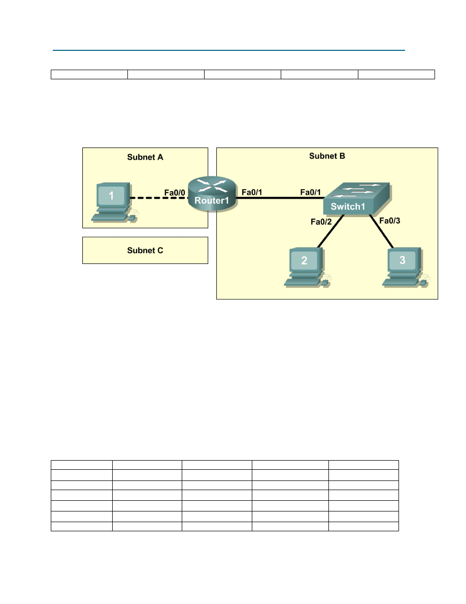
CCNA Exploration
Network Fundamentals:
Configuring and Testing Your Network
Lab 11.5.5 Network Documentation with Utility Commands
All contents are Copyright © 1992–2007 Cisco Systems, Inc. All rights reserved. This document is Cisco Public Information.
Page 3 of 12
What is the bit mask? __________________________
Task 2: Configure the Physical Lab Topology.
Step 1: Physically connect lab devices.
Figure 1. Cabling the network.
Cable the network devices as shown in Figure 1. Pay special attention to the crossover cable required
between Host1 and Router1.
If not already enabled, turn power on to all devices.
Step 2: Visually inspect network connections.
After cabling the network devices, take a moment to verify the connections. Attention to detail now will
minimize the time required to troubleshoot network connectivity issues later.
Task 3: Configure the Logical Topology.
Step 1: Document logical network settings.
Host computers will use the first two IP addresses in the subnetwork. The network router will use the
LAST network host address. Write down the IP address information for each device:
Device
Subnet
IP address
Mask
Gateway
Router1-Fa0/0
Host1
Router1-Fa0/1
Host2
Host3
Switch1
N/A
N/A
N/A
N/A

CCNA Exploration
Network Fundamentals:
Configuring and Testing Your Network
Lab 11.5.5 Network Documentation with Utility Commands
All contents are Copyright © 1992–2007 Cisco Systems, Inc. All rights reserved. This document is Cisco Public Information.
Page 4 of 12
Step 2: Configure host computers.
On each computer in turn, select start | Control Panel | Network Connections. Identify the Local Area
Connection device icon. Use the mouse pointer to highlight the icon, right-click, and select properties.
Highlight Internet Protocol (TCP/IP), and select Properties.
Verify that the Host1 Layer 3 IP address is on a different subnetwork than Host2 and Host3. Configure
each host computer using the IP address information recorded in Step 1.
Verify proper configuration of each host computer with the ipconfig /all command. Record your
information in Appendix1, Network Documentation:
Step 3: Configure Router1.
From the Widows taskbar, start the HyperTerminal program by clicking on Start | Programs | Accessories
| Communications | HyperTerminal. Configure HyperTerminal for access to Router1. Configuration tasks
for Router1 include the following:
Task
Specify Router name- Router1
Specify an encrypted privileged exec password- cisco
Specify a console access password- class
Specify a telnet access password- class
Configure the MOTD banner.
Configure Router1 interface Fa0/0- set the description
set the Layer 3 address
issue no shutdown
Configure Router1 interface Fa0/1- set the description
set the Layer 3 address
issue no shutdown
Save the configuration in NVRAM.
Display the contents of RAM:
Copy the output of the configuration into the Router1 configuration table, Appendix 1.
Copy the output of the show interface fa0/0 and show interface fa0/1 commands into the
Router1 Interface configuration tables, Appendix 1.
Copy the output of the show ip interface brief command into the Router1 IP Address
configuration table, Appendix1.

CCNA Exploration
Network Fundamentals:
Configuring and Testing Your Network
Lab 11.5.5 Network Documentation with Utility Commands
All contents are Copyright © 1992–2007 Cisco Systems, Inc. All rights reserved. This document is Cisco Public Information.
Page 5 of 12
Step 4: Configure Switch1.
Move the console cable from Router1 to Switch1. Press Enter until a response is received. Configuration
tasks for Switch1 include the following:
Task
Specify Switch name- Switch1
Specify an encrypted privileged exec password- cisco
Specify a console access password- class
Specify a telnet access password- class
Configure the MOTD banner.
Configure Switch1 interface Fa0/1- set the description
Configure Switch1 interface Fa0/2- set the description
Configure Switch1 interface Fa0/3- set the description
Display the contents of RAM:
Copy the output of the configuration into the Switch1 configuration table, Appendix 1.
Copy the output of the show mac address-table command into the Switch1 MAC address table,
Appendix 1.
Task 4: Verify Network Connectivity.
Step 1: Use the ping command to verify network connectivity.
Network connectivity can be verified with the ping command. It is very important that connectivity exists
throughout the network. Corrective action must be taken if there is a failure.
**NOTE: If pings to host computers fail, temporarily disable the computer firewall and retest. To disable a
Windows firewall, select Start | Control Panel | Windows Firewall, select OFF, and OK.

CCNA Exploration
Network Fundamentals:
Configuring and Testing Your Network
Lab 11.5.5 Network Documentation with Utility Commands
All contents are Copyright © 1992–2007 Cisco Systems, Inc. All rights reserved. This document is Cisco Public Information.
Page 6 of 12
Use the following table to methodically verify connectivity with each network device. Take corrective
action to establish connectivity if a test fails:
From
To
IP Address
Ping results
Host1
LocalHost (127.0.0.1)
Host1
NIC IP address
Host1
Gateway (Router1, Fa0/0)
Host1
Router1, Fa0/1
Host1
Host2
Host1
Host3
Host2
LocalHost (127.0.0.1)
Host2
NIC IP address
Host2
Host3
Host2
Gateway (Router1, Fa0/1)
Host2
Router1, Fa0/0
Host2
Host1
Host3
LocalHost (127.0.0.1)
Host3
NIC IP address
Host3
Host2
Host3
Gateway (Router1, Fa0/1)
Host3
Router1, Fa0/0
Host3
Host1
Step 2: Use the tracert command to verify local connectivity.
In addition to connectivity testing, the tracert command may also be used as a crude throughput tester for
network baselining. That is, with minimal traffic, tracert results can be compared against periods of high
traffic. Results can be used to justify equipment upgrades or new purchases.
From Host1, issue the tracert command to Router1, Host2, and Host3. Record the results in the Host1
Tracert output, Appendix A.
From Host2, issue the tracert command to Host3, Router1, and Host1. Record the results in the Host2
Tracert output, Appendix A.
From Host3, issue the tracert command to Host2, Router1, and Host1. Record the results in the Host3
Tracert output, Appendix A.
Task 5: Document the Network.
With all the work performed so far, it would seem that there is nothing left to do. The network was
physically and logically configured, verified, and command output copied into tables.

CCNA Exploration
Network Fundamentals:
Configuring and Testing Your Network
Lab 11.5.5 Network Documentation with Utility Commands
All contents are Copyright © 1992–2007 Cisco Systems, Inc. All rights reserved. This document is Cisco Public Information.
Page 7 of 12
The last step in network documentation is to organize your output. As you organize, think what might be
needed six months or a year from now. For example:
When was the network created?
When was the network documented?
Were there any significant challenges that were overcome?
Who performed the configuration (talent like this needs to be tracked)?
Who performed the documentation (talent like this needs to be tracked)?
These questions should be answered in the documentation, perhaps in a cover letter.
Be sure to include the following information:
A copy of the physical topology.
A copy of the logical topology.
Prepare your documentation in a professional format, and submit it to your instructor.
Task 6: Reflection
Review any physical or logical configuration problems encountered during this lab. Insure a thorough
understanding of the procedures used to verify network connectivity.
Task 7: Challenge
Ask your instructor or another student to introduce one or two problems in your network when you aren’t
looking or are out of the lab room. Problems can be either physical (cables moved on the switch) or
logical (wrong IP address or gateway).
Use your network documentation to troubleshoot and remedy the problems:
1. Perform a good visual inspection. Look for green link lights on Switch1.
2. Use your network documentation to compare what should be to what is:
_________________________________________________________________
_________________________________________________________________
_________________________________________________________________
_________________________________________________________________
_________________________________________________________________
3. Write down your proposed solution(s):
_________________________________________________________________
_________________________________________________________________
_________________________________________________________________
_________________________________________________________________
_________________________________________________________________
4. Test your solution. If the solution fixed the problem, document the solution. If the solution did
not fix the problem, continue troubleshooting.
_________________________________________________________________
_________________________________________________________________
_________________________________________________________________
_________________________________________________________________
_________________________________________________________________

CCNA Exploration
Network Fundamentals:
Configuring and Testing Your Network
Lab 11.5.5 Network Documentation with Utility Commands
All contents are Copyright © 1992–2007 Cisco Systems, Inc. All rights reserved. This document is Cisco Public Information.
Page 8 of 12
_________________________________________________________________
Task 6: Cleanup
Unless directed otherwise by the instructor, restore host computer network connectivity, then turn off
power to the host computers.
Before turning off power to the router and switch, remove the NVRAM configuration file from each device
with the privileged exec command erase startup-config.
Carefully remove cables and return them neatly to their storage. Reconnect cables that were
disconnected for this lab.
Remove anything that was brought into the lab, and leave the room ready for the next class.
Appendix 1- Network Documentation
Host tables created from Task 3, Step 2:
Host1 Network Configuration
Host Name
IP Routing Enabled
Ethernet adapter
Description
Physical Address
IP Address
Subnet Mask
Default Gateway
Host2 Network Configuration
Host Name
IP Routing Enabled
Ethernet adapter
Description
Physical Address
IP Address
Subnet Mask
Default Gateway
Host3 Network Configuration
Host Name
IP Routing Enabled
Ethernet adapter
Description
Physical Address
IP Address
Subnet Mask
Default Gateway

CCNA Exploration
Network Fundamentals:
Configuring and Testing Your Network
Lab 11.5.5 Network Documentation with Utility Commands
All contents are Copyright © 1992–2007 Cisco Systems, Inc. All rights reserved. This document is Cisco Public Information.
Page 9 of 12
Router1 configuration from Task 3, Step 3:
Router1 Configuration
Router1 Interface Fa0/0 configuration from Task 2, Step 3:
Router1 Interface fa0/1 configuration from Task 3, Step 3:

CCNA Exploration
Network Fundamentals:
Configuring and Testing Your Network
Lab 11.5.5 Network Documentation with Utility Commands
All contents are Copyright © 1992–2007 Cisco Systems, Inc. All rights reserved. This document is Cisco Public Information. Page 10 of 12
Router1 IP Address configuration from Task 3, Step 3:

CCNA Exploration
Network Fundamentals:
Configuring and Testing Your Network
Lab 11.5.5 Network Documentation with Utility Commands
All contents are Copyright © 1992–2007 Cisco Systems, Inc. All rights reserved. This document is Cisco Public Information. Page 11 of 12
Switch1 Configuration from Task 3, Step 4:
Switch1 MAC address-table from Task 3, Step 4:
Traceroute results from Host1 Task 4, Step 2:

CCNA Exploration
Network Fundamentals:
Configuring and Testing Your Network
Lab 11.5.5 Network Documentation with Utility Commands
All contents are Copyright © 1992–2007 Cisco Systems, Inc. All rights reserved. This document is Cisco Public Information. Page 12 of 12
Traceroute results from Host2 Task 4, Step 2:
Traceroute results from Host3 Task 4, Step 2:
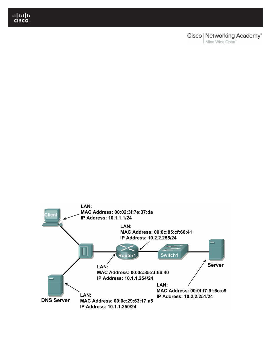
All contents are Copyright © 1992–2007 Cisco Systems, Inc. All rights reserved. This document is Cisco Public Information.
Page 1 of 9
Lab 11.5.6: Final Case Study - Datagram Analysis with Wireshark
Learning Objectives
Upon completion of this exercise, students will be able to demonstrate:
•
How a TCP segment is constructed, and explain the segment fields.
•
How an IP packet is constructed, and explain the packet fields.
•
How an Ethernet II frame is constructed, and explain the frame fields.
•
Contents of an ARP REQUEST and ARP REPLY.
Background
This lab requires two captured packet files and Wireshark, a network protocol analyzer. Download the
following files from Eagle server, and install Wireshark on your computer if it is not already installed:
•
eagle1_web_client.pcap (discussed)
•
eagle1_web_server.pcap (reference only)
•
wireshark.exe
Scenario
This exercise details the sequence of datagrams that are created and sent across a network between a web
client, PC_Client, and web server, eagle1.example.com. Understanding the process involved in sequentially
placing packets on the network will enable the student to logically troubleshoot network failures when
connectivity breaks. For brevity and clarity, network packet noise has been omitted from the captures.
Before executing a network protocol analyzer on a network that belongs to someone else, be sure to get
permission- in writing.
Figure 1 shows the topology of this lab.
Figure 1. Network Topology.
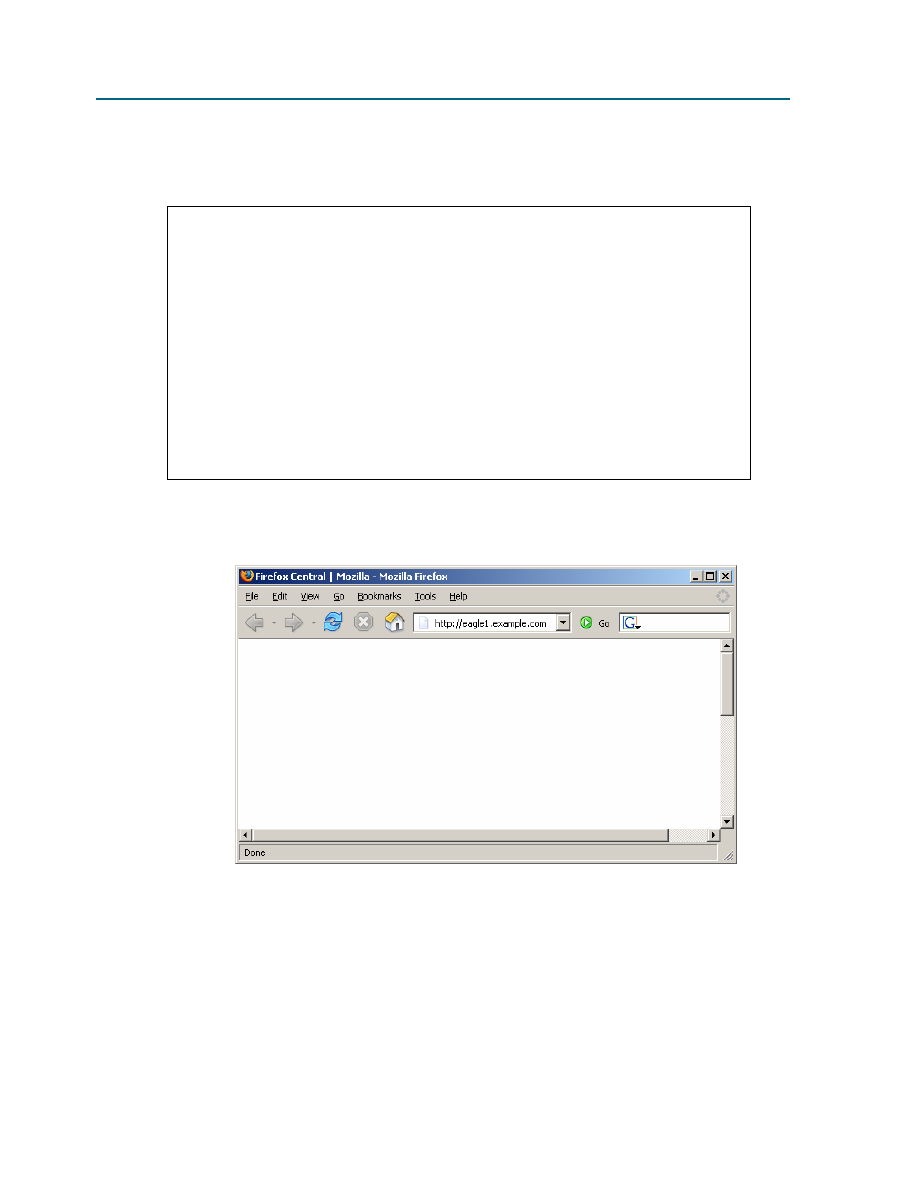
CCNA Exploration
Network Fundamentals:
Configuring and Testing Your Network
Lab 11.5.6: Final Case Study - Datagram Analysis with Wireshark
All contents are Copyright © 1992–2007 Cisco Systems, Inc. All rights reserved. This document is Cisco Public Information.
Page 2 of 9
Using Microsoft ® command line tools, IP configuration information and the contents of ARP cache are
displayed. Refer to Figure 2.
C: >
ipconfig / all
Windows IP Configuration
Ethernet adapter Local Area Connection:
Connection-specific DNS Suffix . :
Description . . . . . . . . . . . : Intel(R) PRO/1000 MT
Network Connection
Physical Address. . . . . . . . . : 00:02:3f:7e:37:da
Dhcp Enabled. . . . . . . . . . . : No
IP Address. . . . . . . . . . . . : 10.1.1.1
Subnet Mask . . . . . . . . . . . : 255.255.255.0
Default Gateway . . . . . . . . . : 10.1.1.254
DNS Servers . . . . . . . . . . . : 10.1.1.250
C: >
arp –a
No ARP Entries Found
C: >
Figure 2. PC Client initial network state.
A web client is started, and URL eagle1.example.com is entered, as shown in Figure 3. This begins
the communication process to the web server, and where the captured packets start.
Figure 3. PC Client with web browser.
Task 1: Prepare the Lab.
Step 1: Start Wireshark on your computer.
Refer to Figure 4 for changes to the default output. Uncheck Main toolbar, Filter toolbar, and
Packet Bytes
. Verify that Packet List and Packet Details are checked. To insure there is no
automatic translation in MAC addresses, de-select Name Resolution for MAC layer and Transport
Layer
.
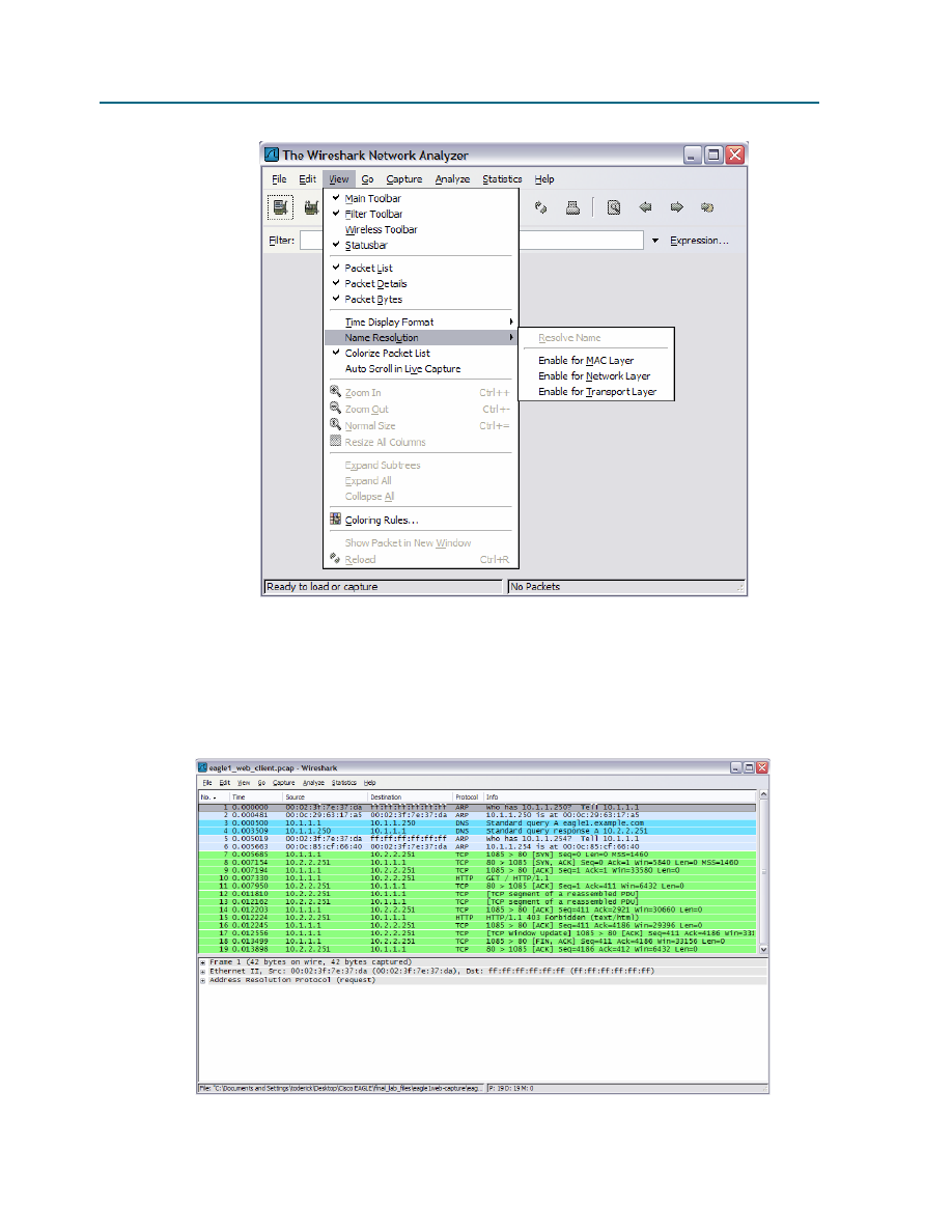
CCNA Exploration
Network Fundamentals:
Configuring and Testing Your Network
Lab 11.5.6: Final Case Study - Datagram Analysis with Wireshark
All contents are Copyright © 1992–2007 Cisco Systems, Inc. All rights reserved. This document is Cisco Public Information.
Page 3 of 9
Figure 4. Wireshark default view changes.
Step 2: Load the web client capture, eagle1_web_client.pcap.
A screen similar to Figure 5 will be displayed. Various pull-down menus and sub-menus are available. There
are also two separate data windows. The top Wireshark window lists all captured packets. The bottom
window contains packet details. In the bottom window, each line that contains a check box, indicates that
additional information is available.
Figure 5. Wireshark with file eagle1_web_client.pcap loaded.

CCNA Exploration
Network Fundamentals:
Configuring and Testing Your Network
Lab 11.5.6: Final Case Study - Datagram Analysis with Wireshark
All contents are Copyright © 1992–2007 Cisco Systems, Inc. All rights reserved. This document is Cisco Public Information.
Page 4 of 9
Task 2: Review the Process of Data Flowing through the Network.
Step 1: Review Transport layer operation.
When PC_Client builds the datagram for a connection with eagle1.example.com, the datagram travels down
the various network Layers. At each Layer, important header information is added. Because this
communication is from a web client, the Transport Layer protocol will be TCP. Consider the TCP segment,
shown in Figure 6. PC_Client generates an internal TCP port address, in this conversation 1085, and knows
the well-known web server port address, 80. Likewise, a sequence number has been internally generated.
Data is included, provided by the Application Layer. Some information will not be known to PC_Client, so it
must be discovered using other network protocols.
There is no acknowledgement number. Before this segment can move to the Network Layer, the TCP three-
way handshake must be performed.
16
TCP Segment
Source Port
Source Port
Destination Port
Destination Port
0
31
Sequence Number
Sequence Number
Acknowledgement Number
Acknowledgement Number
Data Offset
Data Offset
4
7
Reserved
Reserved
ECN
ECN
10
Control Bits
Control Bits
Window
Window
Checksum
Checksum
Urgent Pointer
Urgent Pointer
Options and Padding
Options and Padding
Data
Data
Figure 6. TCP Segment fields.
Step 2: Review Network layer operation.
At the Network Layer, the IPv4 (IP) PACKET has several fields ready with information. This is shown in
Figure 7. For example, the packet Version (IPv4) is known, as well as the source IP address.
The destination for this packet is eagle1.example.com. The corresponding IP Address must be discovered
through DNS (Domain Name Services). Until the upper layer datagram is received, fields related to the
upper layer protocols are empty.
16
IP Packet
Total Length
Total Length
0
31
4
8
10
Source IP Address
Source IP Address
Data
Data
Version
Version
IHL
IHL
TOS
TOS
Identification
Identification
Flags
Flags
Fragment Offset
Fragment Offset
TTL
TTL
Protocol
Protocol
Header Checksum
Header Checksum
Destination IP Address
Destination IP Address
Figure 7. IP Packet fields.

CCNA Exploration
Network Fundamentals:
Configuring and Testing Your Network
Lab 11.5.6: Final Case Study - Datagram Analysis with Wireshark
All contents are Copyright © 1992–2007 Cisco Systems, Inc. All rights reserved. This document is Cisco Public Information.
Page 5 of 9
Step 3: Review Data Link layer operation.
Before the datagram is placed on the physical medium, it must be encapsulated inside a frame. This is
shown in Figure 8. PC_Client has knowledge of the source MAC address, but must discover the destination
MAC address.
The destination MAC address must be discovered.
Preamble
8 Octets
Destination
Address
6 Octets
Source
Address
6 Octets
Frame
Type
2 Octets
Data
46-1500 Octets
CRC
4 Octets
Ethernet II Frame Format
Figure 8. Ethernet II frame fields.
Task 3: Analyze Captured Packets.
Step 1: Review the data flow sequence.
A review of missing information will be helpful in following the captured packet sequence:
a. The TCP segment cannot be constructed because the acknowledgement field is blank. A TCP 3-
way handshake with eagle1.example.com must first be completed.
b. The TCP 3-way handshake cannot occur because PC_Client does not know the IP address for
eagle1.example.com. This is resolved with a DNS request from PC_Client to the DNS the server.
c. The DNS server cannot be queried because the MAC address for the DNS server is not known. The
ARP protocol is broadcast on the LAN to discover the MAC address for the DNS server.
d. The MAC address for eagle1.example.com is unknown. The ARP protocol is broadcast on the LAN
to learn the destination MAC address for eagle1.example.com.
Step 2: Examine the ARP request.
Refer to Wireshark, Packet List window, No. 1. The captured frame is an ARP (Address Resolution Protocol)
Request. Contents of the Ethernet II frame can be viewed by clicking on the check box in the second line of
the Packet Details window. Contents of the ARP Request can be viewed by clicking on the ARP Request
line in the Packet Details window.
1. What is the source MAC address for the ARP Request? _____________________
2. What is the destination MAC address for the ARP Request? _____________________
3. What is the unknown IP address in the ARP Request? ______________________
4. What is the Ethernet II Frame Type? _____________________

CCNA Exploration
Network Fundamentals:
Configuring and Testing Your Network
Lab 11.5.6: Final Case Study - Datagram Analysis with Wireshark
All contents are Copyright © 1992–2007 Cisco Systems, Inc. All rights reserved. This document is Cisco Public Information.
Page 6 of 9
Step 3: Examine the ARP reply.
Refer to Wireshark, Packet List window, No. 2. The DNS server sent an ARP Reply.
1. What is the source MAC address for the ARP Reply? _____________________
2. What is the destination MAC address for the ARP Request? _____________________
3. What is the Ethernet II Frame Type? _____________________
4. What is the destination IP address in the ARP Reply? _____________________
5. Based on the observation of the ARP protocol, what can be inferred about an ARP Request
destination address and an ARP Reply destination address?
_____________________________________________________________________
_____________________________________________________________________
_____________________________________________________________________
6. Why did the DNS server not have to send an ARP Request for the PC_Client MAC address?
_____________________________________________________________
_____________________________________________________________________
Step 4: Examine the DNS query.
Refer to Wireshark, Packet List window, No. 3. PC_Client sent a DNS query to the DNS server. Using the
Packet Details window, answer the following questions:
1. What is the Ethernet II Frame Type? _____________________
2. What is the Transport Layer protocol, and what is the destination port number?
_____________________
Step 5: Examine the DNS query response.
Refer to Wireshark, Packet List window, No. 4. The DNS server sent a DNS query response to PC_Client.
Using the Packet Details window, answer the following questions:
1. What is the Ethernet II Frame Type? _____________________
2. What is the Transport Layer protocol, and what is the destination port number?
_____________________
3. What is the IP address for eagle1.example.com? _____________________
4. A colleague is a firewall administrator, and asked if you thought of any reason why all UDP packets
should not be blocked from entering the internal network. What is your response?
_____________________
_____________________________________________________________________
_____________________________________________________________________
_____________________________________________________________________

CCNA Exploration
Network Fundamentals:
Configuring and Testing Your Network
Lab 11.5.6: Final Case Study - Datagram Analysis with Wireshark
All contents are Copyright © 1992–2007 Cisco Systems, Inc. All rights reserved. This document is Cisco Public Information.
Page 7 of 9
Step 6: Examine the ARP request.
Refer to Wireshark, Packet List window, No. 5 and No 6. PC_Client sent an ARP Request to IP address
10.1.1.254.
1. Is this IP address different than the IP address for eagle1.example.com? Explain?
____________________________________________________________________
____________________________________________________________________
Step 7: Examine the TCP 3-way handshake.
Refer to Wireshark, Packet List window, No. 7, No. 8, and No. 9. These captures contain the TCP 3-way
handshake between PC_Client and eagle1.example.com. Initially, only the TCP SYN flag is set on the
datagram sent from PC_Client, sequence number 0. eagle1.example.com responds with the TCP ACK and
SYN flags set, along with an acknowledgement of 1 and sequence of 0. In the Packet List window, there is
an unexplained value, MSS=1460. MSS stands for Maximum Segment size. When a TCP segment is
transported over IPv4, MSS is computed to be the maximum size of an IPv4 datagram minus 40 bytes. This
value is sent during connection startup. This is also when TCP sliding windows are negotiated.
1. If the initial TCP sequence value from PC_Client is 0, why did eagle1.example respond with an
acknowledgement of 1?
____________________________________________________________________
____________________________________________________________________
2. In eagle1.example.com, No. 8, What does the IP Flag value of 0x04 mean?
____________________________________________________________________
3. When PC_Client completes the TCP 3-way handshake, Wireshark Packet List No 9, what are the
TCP flag states returned to eagle1.example.com?
____________________________________________________________________
Task 4: Complete the Final Analysis.
Step 1: Match the Wireshark output to the process.
It has taken a total of nine datagrams sent between PC_Client, DNS server, Gateway, and
eagle1.example.com before PC_Client has sufficient information to send the original web client request to
eagle1.example.com. This is shown in Wireshark Packet List No. 10, where PC_Client sent a web protocol
GET request.
1. Fill in the correct Wireshark Packet List number that satisfies each of the following missing entries:
a. The TCP segment cannot be constructed because the acknowledgement field is blank. A TCP
3-way handshake with eagle1.example.com must first be completed. ________
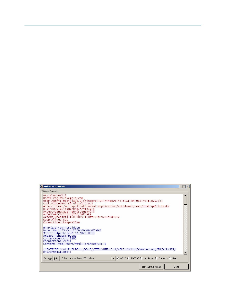
CCNA Exploration
Network Fundamentals:
Configuring and Testing Your Network
Lab 11.5.6: Final Case Study - Datagram Analysis with Wireshark
All contents are Copyright © 1992–2007 Cisco Systems, Inc. All rights reserved. This document is Cisco Public Information.
Page 8 of 9
b. The TCP 3-way handshake cannot occur because PC_Client does not know the IP address for
eagle1.example.com. This is resolved with a DNS request from PC_Client to the DNS the
server. ________
c. The DNS server cannot be queried because the MAC address for the DNS server is not known.
The ARP protocol is broadcast on the LAN to discover the MAC address for the DNS server.
________
d. The MAC address for the gateway to reach eagle1.example.com is unknown. The ARP protocol
is broadcast on the LAN to learn the destination MAC address for the gateway. ________
1. Wireshark Packet List No. 11 is an acknowledgement from eagle1.example.com to the PC_Client
GET request, Wireshark Packet List No. 10.
2. Wireshark Packet List No. 12, 13 and 15 are TCP segments from eagle1.example.com. Wireshark
Packet List No. 14 and 16 are ACK datagrams from PC_Client.
3. To verify the ACK, highlight Wireshark Packet List No. 14. Next, scroll down to the bottom of the
detail list window, and expand the [SEQ/ACK analysis] frame. The ACK datagram for Wireshark
Packet List No. 14 is a response to which datagram from eagle1.example.com? _______________
4. Wireshark Packet List No. 17 datagram is sent from PC_Client to eagle1.example.com. Review the
information inside the [SEQ/ACK analysis] frame. What is the purpose of this datagram?
5. When PC_Client is finished, TCP ACK and FIN flags are sent, shown in Wireshark Packet List No.
18. eagle1.example.com responds with a TCP ACK, and the TCP session is closed.
Step 2: Use Wireshark TCP Stream.
Analyzing packet contents can be a daunting experience, time consuming and error prone. Wireshark
includes an option that constructs the TCP Stream in a separate window. To use this feature, first select a
TCP datagram from the Wireshark Packet List. Next, select Wireshark menu options Analyze | Follow TCP
Stream. A window similar to Figure 9 will be displayed.

CCNA Exploration
Network Fundamentals:
Configuring and Testing Your Network
Lab 11.5.6: Final Case Study - Datagram Analysis with Wireshark
All contents are Copyright © 1992–2007 Cisco Systems, Inc. All rights reserved. This document is Cisco Public Information.
Page 9 of 9
Figure 9. Output of the TCP stream.
Task 5: Conclusion
Using a network protocol analyzer can serve as an effective learning tool for understanding critical elements
of network communication. Once the network administrator is familiar with communication protocols, the
same protocol analyzer can become an effective troubleshooting tool when there is network failure. For
example, if a web browser could not connect to a web server there could be multiple causes. A protocol
analyzer will show unsuccessful ARP requests, unsuccessful DNS queries, and unacknowledged packets.
Task 6: Summary
In this exercise the student has learned how communication between a web client and web server
communicate. Behind-the-scene protocols such as DNS and ARP are used to fill in missing parts of IP
packets and Ethernet frames, respectively. Before TCP session can begin, the TCP 3-way handshake must
build a reliable path and supply both communicating ends with initial TCP header information. Finally, the
TCP session is destroyed in an orderly manner with the client issuing a TCP FIN flag.
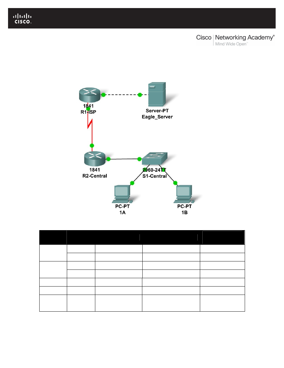
All contents are Copyright © 1992–2007 Cisco Systems, Inc. All rights reserved. This document is Cisco Public Information.
Page 1 of 4
11.6.1: Skills Integration Challenge-Configuring and Testing the
Lab Network
Topology Diagram
Addressing Table
Device
Interface
IP Address
Subnet Mask
Default
Gateway
Fa0/0
N/A
R1-ISP
S0/0/0
N/A
Fa0/0
R2-
Central
S0/0/0
PC 1A
NIC
PC 1B
NIC
Eagle
Server
NIC

CCNA Exploration
Network Fundamentals:
Configuring and Testing Your Network 11.6.1: Skills Integration Challenge-Configuring and Testing the Lab Network
All contents are Copyright © 1992–2007 Cisco Systems, Inc. All rights reserved. This document is Cisco Public Information.
Page 2 of 4
Learning Objectives
•
Build, test, and configure the entire lab network.
o
Integrate skills from throughout the course.
•
Analzye the events involved in:
o
Requesting a web page (DNS, ARP, HTTP, TCP, IP, Ethernet, HDLC).
o
Tracing the route to the web server (DNS, UDP, ARP, ICMP, IP, Ethernet,
HDLC)
Background
Throughout the course, you have been developing network planning, building, configuring, and
testing skills. You have also developed conceptual understandings of networking protocols and
device algorithms. Here is an opportunity to test yourself: see if you can complete the entire
challenge (approximately 100 configurable components, though some are quite easy) in under 30
minutes.
Task 1: Plan.
Use the standard Exploration lab topology as you plan your IP addressing scheme:
•
Two 1841 routers with WIC-2T interface cards, installed in the right hand slot (one named
R1-ISP, which has the serial DCE WAN connection to R2-Central, and the Fa0/0 LAN
connection to Eagle_Server) and one named R2-Central (which has the serial DCE WAN
connection to R1-ISP and the Fa0/0 LAN connection to S1-Central)
•
One 2960TT Switch (S1-Central)
•
Two PCs named 1A and 1B
•
A server named Eagle_Server.
Note that both the Display names AND host names for all devices must be configured exactly,
and in general all strings (names, passwords, banners) should be typed exactly as specified in
these instructions, for the grading to work properly.
You have been given an IP address block of 192.168.3.0 /24. You must provide for existing
networks as well as future growth.
Subnet assignments are:
•
1st subnet, existing student LAN, up to 28 hosts (Fa0/0 on R2-Central, connected to
Fa0/24 on S1-Central)
•
2nd subnet, future student LAN, up to 28 hosts (not yet implemented)
•
3rd subnet, existing ISP LAN, up to 14 hosts (Fa0/0 on R1-ISP)
•
4th subnet, future ISP LAN, up to 7 hosts (not yet implemented)
•
5th subnet, existing WAN, point-to-point link (S0/0/0 on R1-ISP and S0/0/0 on R2-
Central)

CCNA Exploration
Network Fundamentals:
Configuring and Testing Your Network 11.6.1: Skills Integration Challenge-Configuring and Testing the Lab Network
All contents are Copyright © 1992–2007 Cisco Systems, Inc. All rights reserved. This document is Cisco Public Information.
Page 3 of 4
IP address assignments are:
•
For the server, configure the second highest usable IP address on the ISP LAN subnet.
•
For R1-ISP's Fa0/0 interface, configure the highest usable IP address on the ISP LAN
subnet.
•
For R1-ISP's S0/0/0 interface, configure the highest usable address on the existing WAN
subnet.
•
For R2-Central's S0/0/0 interface, use the lowest usable address on the existing WAN
subnet.
•
For R2-Central's Fa0/0 interface, use the highest usable address on the existing student
LAN subnet and connect it to the Fa0/24 interface on S1-Central.
•
For hosts 1A and 1B, use the first 2 IP addresses (two lowest usable addresses) on the
existing student LAN subnet and connect them to the Fa0/1 and Fa0/2 interfaces on S1-
Central.
•
For the switch management interface, use the second highest usable address on the
student subnet.
Task 2: Build and Configure the Network.
Build the network, taking care to make connections as specified. Configure both routers, the
switch, the server, and the two PCs.
Configure the routers using the CLI to practice your skills. The router configuration must include
"housekeeping" (display name, hostname, passwords, banner), interfaces (Fast Ethernet and
Serial), and routing (static route on R1-ISP, default route on R2-Central). The following login
passwords should all be set to "cisco" (no quotes): enable, console, and Telnet. The banners
should say **This is lab router R1-ISP. Authorized access only.** and **This is lab router R2-
Central. Authorized access only.**
The interfaces should be configured as specified in the IP addressing section above; use a clock
rate of 64000 on the R1-ISP S0/0/0 interface. The static route on R1-ISP should point to the
existing Student LAN subnet via R2-Central's serial interface IP address; the static route on R2-
Central should be a default static route which points via R1-ISP's serial interface IP address.
Whenever you configure a Cisco IOS device, be sure to save your configuration.
On the switch, configure the display name, hostname, banner (**This is lab switch S1-Central.
Authorized access only.**), login passwords for access (enable, console, and Telnet passwords
all set to "cisco"), and management interface (int vlan1). Whenever you configure a Cisco IOS
device, be sure to save your configuration.
For Hosts 1A and 1B, in addition to IP configuration, configure them to use DNS services. For the
server, enable DNS services, use the domain name eagle-server.example.com, and enable
HTTP services.
As you work, use "Check Results" to see what components still need to be configured. If you
want more practice, use "Reset Activity" and re-time yourself doing the entire configuration again.

CCNA Exploration
Network Fundamentals:
Configuring and Testing Your Network 11.6.1: Skills Integration Challenge-Configuring and Testing the Lab Network
All contents are Copyright © 1992–2007 Cisco Systems, Inc. All rights reserved. This document is Cisco Public Information.
Page 4 of 4
Task 3: Test and Analzye.
It is a good practice to test connectivity through ping and Telnet, and to examine routing tables.
Once you are convinced your network is working, make sure you have saved your configurations
on the Cisco IOS devices. Then power cycle the devices, and reset the network. In simulation
mode, request a web page while making the following protocols visible in the event list: DNS,
HTTP, Telnet, TCP, UDP, ICMP, ARP. Examine the packets as they are processed by the
devices to study protocol behavior, especially how IP is involved in everything. Also note the
algorithms used by hosts, switches, and routers. Explain the entire process to a peer. Power
cycle the devices to clear the network again, and, also in simulation mode, issue a traceroute to
the server from one of the PCs. Examine how trace is built up of ICMP echo requests. Again
explain the entire process to a peer.
Reflection
Relate the processes observed in Task 3 to the TCP/IP Protocol Graph. Your skills at modeling
networks in Packet Tracer will serve you well in subsequent courses.
Document Outline
- Chapter 1
- Chapter 2
- Chapter 3
- Chapter 4
- Chapter 5
- Chapter 6
- Chapter 7
- Chapter 8
- Chapter 9
- Chapter 10
- Chapter 11
- 11.4.3.3: Network Latency Documentation with Ping
- Lab 11.5.1: Basic Cisco Device Configuration
- Lab 11.5.2: Managing Device Configuration
- Lab 11.5.3: Configure Host Computers for IP Networking
- Lab 11.5.4: Network Testing
- Lab 11.5.5: Network Documentation with Utility Commands
- Lab 11.5.6: Final Case Study - Datagram Analysis with Wireshark
- 11.6.1: Skills Integration Challenge-Configuring and Testing the Lab Network
Wyszukiwarka
Podobne podstrony:
Cisco CCNA Lab Manual
5 XCyte lab manual
Forensic Lab Manual
Lab 2 student
LAB 7 Systemy cyfrowe Modulacja Demodulacja FSK PSK ASK student
imir-lab pytania dla studentow, AGH, I & II, Elektrotechnika
Electrical Safety Student Manual
INSTRUKCJA BHP DLA STUDENTÓW WYKONUJĄCYCH ĆWICZENIA W LAB OiSE
Lab 5, student
Lab 4 student 1(2)
59487272 Accessing the WAN Student Skills Based Assessment Lab Answer Key
Wytyczne lab, student - informatyka, wykłady, Architekt-komp-MarekM
LAB 1 INF - MATLAB, student
LAB 3 INF - MATLAB GUI, student
Interakcje leków i diety z metodami lab materiały dla studentów dietetyki
E2 Lab 11 6 2 instructor, Procedural Lab Template, Student Version, Required Components
Pass Lab X2 SERVICE MANUAL ver 1
Lab 3 student
więcej podobnych podstron