
Copyright © 1999 Wimborne Publishing Ltd and
Maxfield & Montrose Interactive Inc
EPE Online, Febuary 1999 - www.epemag.com - XXX
Volume 3 Issue 1
February 2001

Copyright
2001, Wimborne Publishing Ltd
(Allen House, East Borough, Wimborne, Dorset, BH21 1PF, UK)
and Maxfield & Montrose Interactive Inc.,
(PO Box 857, Madison, Alabama 35758, USA)
All rights reserved.
WARNING!
The materials and works contained within EPE Online — which are made
available by Wimborne Publishing Ltd and Maxfield & Montrose Interactive Inc —
are copyrighted. You are permitted to make a backup copy of the downloaded file
and one (1) hard copy of such materials and works for your personal use.
International copyright laws, however, prohibit any further copying or
reproduction of such materials and works, or any republication of any kind.
Maxfield & Montrose Interactive Inc and Wimborne Publishing Ltd have used
their best efforts in preparing these materials and works. However, Maxfield &
Montrose Interactive Inc and Wimborne Publishing Ltd make no warranties of
any kind, expressed or implied, with regard to the documentation or data
contained herein, and specifically disclaim, without limitation, any implied
warranties of merchantability and fitness for a particular purpose.
Because of possible variances in the quality and condition of materials and
workmanship used by readers, EPE Online, its publishers and agents disclaim
any responsibility for the safe and proper functioning of reader-constructed
projects based on or from information published in these materials and works.
In no event shall Maxfield & Montrose Interactive Inc or Wimborne Publishing Ltd
be responsible or liable for any loss of profit or any other commercial damages,
including but not limited to special, incidental, consequential, or any other
damages in connection with or arising out of furnishing, performance, or use of
these materials and works.
ISSN 0262 3617
PROJECTS . . . THEORY . . . NEWS . . .
COMMENTS . . . POPULAR FEATURES . . .
VOL. 30. No. 2 FEBRUARY 2001
Cover illustration by Jonathan Robertson
Everyday Practical Electronics, February 2001
81
© Wimborne Publishing Ltd 2001. Copyright in all
drawings, photographs and articles published in
EVERYDAY PRACTICAL ELECTRONICS is fully
protected, and reproduction or imitations in whole or
in part are expressly forbidden.
Our March 2001 issue will be published on Thursday,
8 February 2001. See page 83 for details
Readers Services
)) Editorial and Advertisement Departments 91
www.epemag.wimborne.co.uk
EPE Online:
www.epemag.com
P
Prroojjeeccttss a
anndd C
Ciirrccuuiittss
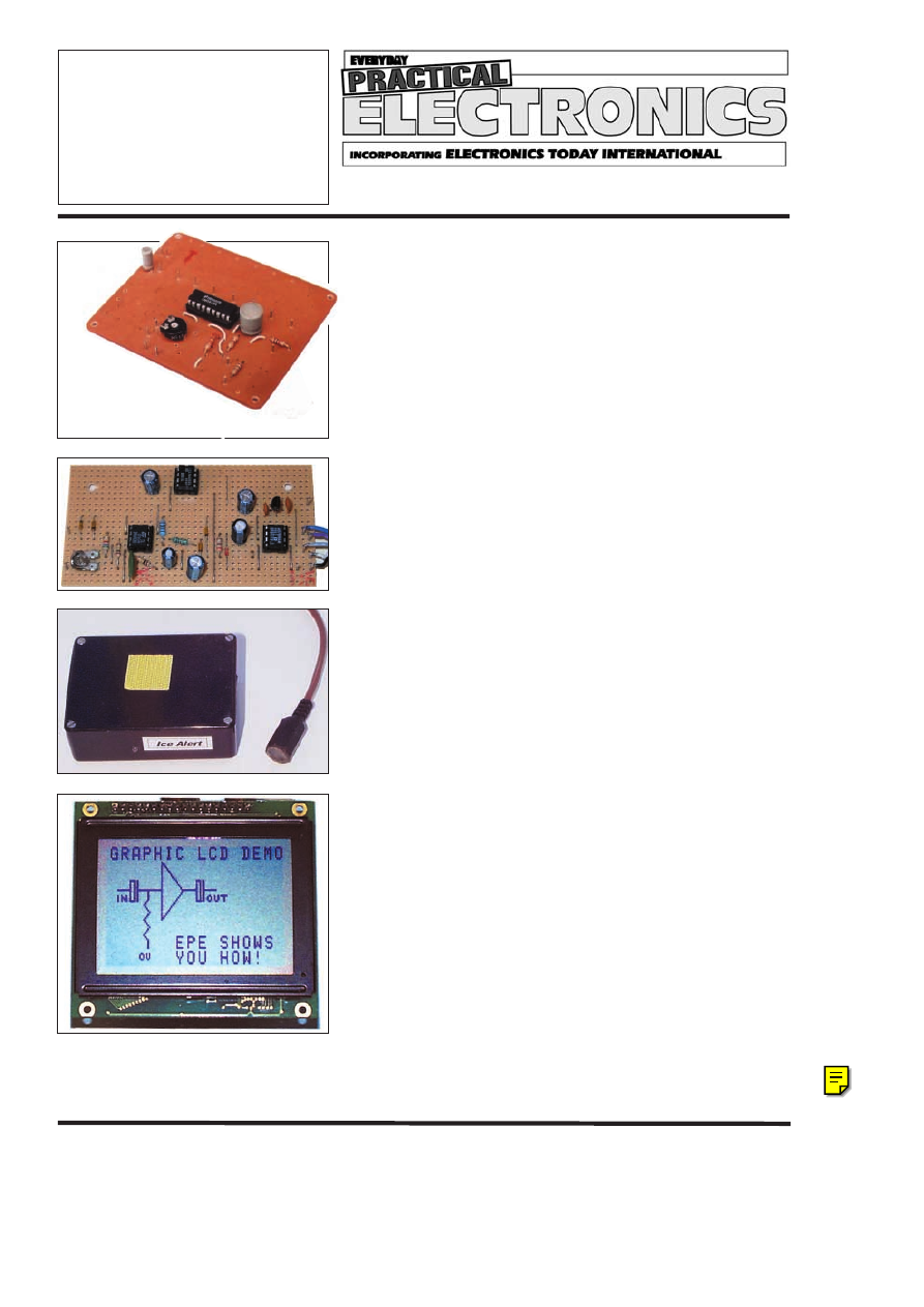
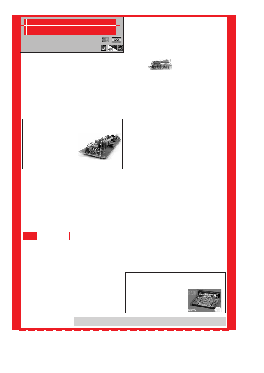
ICE ALERT by Terry de Vaux-Balbirnie
Tri-colour l.e.d. warns motorists and gardeners of impending frost danger
SIMPLE METRONOME by Owen Bishop
with another Top-Tenner project!
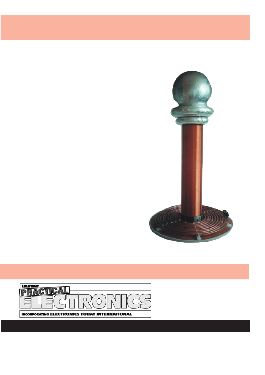
PC AUDIO POWER METER by Robert Penfold
Measures audio amplifier power output via your PC computer
USING LM3914-6 BARGRAPH DRIVERS by Raymond Haigh
A designer’s guide to this versatile range of voltage monitoring devices
INGENUITY UNLIMITED hosted by Alan Winstanley
S
Seerriieess a
anndd F
Feea
attuurreess
NEW TECHNOLOGY UPDATE by Ian Poole
Organic l.e.d.s make their appearance
CIRCUIT SURGERY by Alan Winstanley and Ian Bell
Voltage multipliers; More on Multimeters
NET WORK – THE INTERNET PAGE surfed by Alan Winstanley
Net browser formats
THE SCHMITT TRIGGER – 4. Astable, PWM, Triangle Waveforms,
Transducer Interface by Anthony H. Smith
A designers’ guide to investigating and using Schmitt triggers
R
Reegguulla
arrss a
anndd S
Seerrvviicceess
NEWS – Barry Fox highlights technology’s leading edge
Plus everyday news from the world of electronics
SHOPTALK with David Barrington
Essential reference works for hobbyists, students and service engineers
READOUT John Becker addresses general points arising
ELECTRONICS VIDEOS Our range of educational videos
Teach-In 2000; Electronic Projects; Filters; Digital Works 3.0; Parts
Gallery + Electronic Circuits and Components; Digital Electronics; Analogue
Electronics; PICtutor; Modular Circuit Design; Electronic Components Photos;
C For PIC Micros; CAD Pack
BACK ISSUES Did you miss these? Some now on CD-ROM!
A wide range of technical books available by mail order
PRINTED CIRCUIT BOARD AND SOFTWARE SERVICE
F
Frreeee 1
16
6--P
Pa
aggee S
Suup
pp
plleem
meenntt
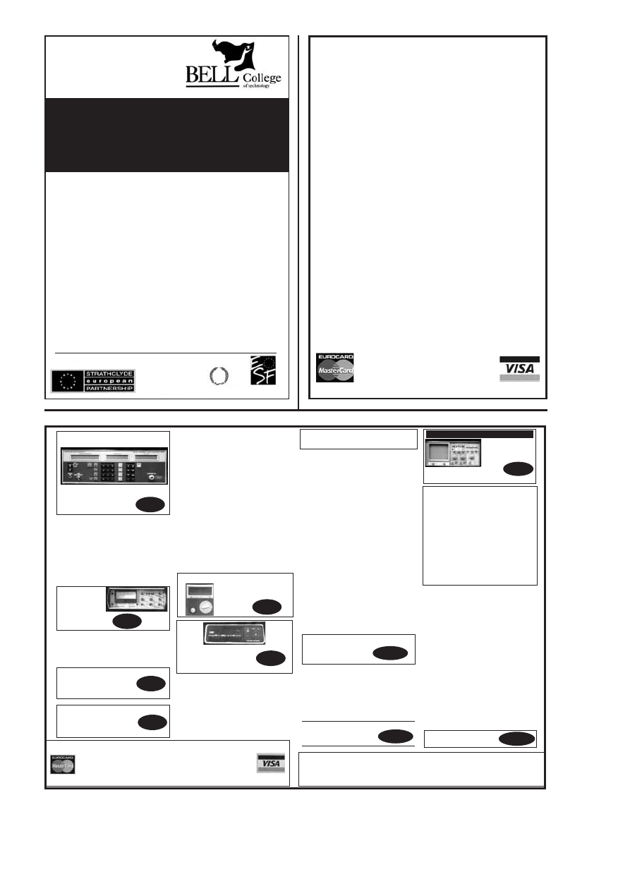
HOW TO USE GRAPHICS L.C.D.S WITH PICS by John Becker
Between 116 and 117
A step-by-step guide to understanding and using pixel-matrixed graphics
liquid crystal displays with your PIC microcontroller projects
NO ONE DOES IT BETTER
DON'T MISS AN
ISSUE – PLACE YOUR
ORDER NOW!
Demand is bound to be high
MARCH 2001 ISSUE ON SALE THURSDAY, FEBRUARY 8
Everyday Practical Electronics, February 2001
83
PLUS ALL THE REGULAR FEATURES
NEXT MONTH
D
DIIY
Y L
LIIG
GH
HT
TN
NIIN
NG
G
Short of divine intervention, most of us are never going to get to control
nature’s most spectacular effect. However, thanks to the genius of a
144-year-old physicist, you can.
The purpose of this article is to allow you, the reader, to build a working
Tesla coil (see photo) with an arc output of at least 50cm, giving you a
general idea as to why and how it works and a few ideas for some of the
fun effects that can be demonstrated with it. But, be warned, the output
from this project is easily capable of killing you if not treated with due
respect.
D
DO
OO
OR
RB
BE
EL
LL
L E
EX
XT
TE
EN
ND
DE
ER
R
This “through the mains’’ unit will extend your doorbell so you can hear it
in the garage or workshop. It will also act as a control system to switch
on or off a remote appliance from the comfort of your armchair, or as a
safety button for the bed-ridden etc.
B
BO
OD
DY
Y D
DE
ET
TE
EC
CT
TO
OR
R
Capacitance is an extraordinary phenomenon, in that it is able to work
through empty space. This is a quality that is normally taken for granted.
The accumulation of charge on a metal plate gives rise to an electric
field, which will affect another plate in direct proportion to the inverse of
its distance. Capacitance, also, is one of a vast range of physical
phenomena that may be translated into electrical oscillations.
The Body Detector featured in this article relies on the fact that the
human body itself possesses a fairly large order of capacitance to the
ground, and that if such a body approaches the positive plate of a given
capacitor, its value will rise.
Due to its high sensitivity and good stability, the Body Detector may be
attached to a wide variety of metal objects – in the process sensitising
the entire object concerned.
Although in theory the Body Detector is dependent on the electric
field which surrounds the human body, in
effect
it acts as though
an invisible field were created around the object concerned –
similar to the “invisible’’ defence shields seen in the latest
Star Wars
movie.
Q
UASAR
E
LECTRONICS
L
imited
Unit 14 Sunningdale, BISHOPS STORTFORD, Herts. CM23 2PA
TEL: 01279 306504 FAX: 07092 203496
ADD £2.00 P&P to all orders (or 1st Class Recorded £4, Next day
(Insured £250) £7, Europe £4.00, Rest of World £6.00). We accept all
major credit cards. Make cheques/PO's payable to Quasar Electronics.
Prices include 17.5% VAT. MAIL ORDER ONLY
FREE CATALOGUE with order or send 2 x 1st class stamps
(refundable) for details of over 150 kits & publications.
Established 1990
FACTOR
PUBLICATIONS
*
* ANIMAL SOUNDS Cat, dog, chicken & cow. Ideal
for kids farmyard toys & schools. SG10M £6.95
*
* 3 1/2 DIGIT LED PANEL METER Use for basic
voltage/current displays or customise to measure
temperature, light, weight, movement, sound lev-
els, etc. with appropriate sensors (not supplied).
Various input circuit designs provided. 3061KT
£13.95
*
* IR REMOTE TOGGLE SWITCH Use any TV/VCR
remote control unit to switch onboard 12V/1A relay
on/off. 3058KT £10.95
SPEED CONTROLLER for any common DC motor up
to 100V/5A. Pulse width modulation gives maximum
torque at all speeds. 5-15VDC. Box provided. 3067KT
£12.95
*
* 3 x 8 CHANNEL IR RELAY BOARD Control eight 12V/1A
relays by Infra Red (IR) remote control over a 20m range in
sunlight. 6 relays turn on only, the other 2 toggle on/off. 3 oper-
ation ranges determined by jumpers. Transmitter case & all
components provided. Receiver PCB 76x89mm. 3072KT
£52.95
*
* PC CONTROLLED RELAY BOARD
Convert any 286 upward PC into a dedicated
automatic controller to independently turn on/off
up to eight lights, motors & other devices around
the home, office, laboratory or factory using 8
240VAC/12A onboard relays. DOS utilities, sample
test program, full-featured Windows utility & all
components (except cable) provided. 12VDC. PCB
70x200mm. 3074KT £31.95
*
* 2 CHANNEL UHF RELAY SWITCH Contains the
same transmitter/receiver pair as 30A15 below plus
the components and PCB to control two
240VAC/10A relays (also supplied). Ultra bright
LEDs used to indicate relay status. 3082KT £27.95
*
* TRANSMITTER RECEIVER PAIR 2-button keyfob
style 300-375MHz Tx with 30m range. Receiver
encoder module with matched decoder IC.
Components must be built into a circuit like kit 3082
above. 30A15 £14.95
*
* PC DATA ACQUISITION/CONTROL UNIT Use your
PC to monitor physical variables (e.g. pressure, tem-
perature, light, weight, switch state, movement, relays,
etc.), process the information & use results to control
physical devices like motors, sirens, relays, servo &
stepper motors. Inputs: 16 digital & 11 analogue.
Outputs: 8 digital & 1 analogue. Plastic case with print-
ed front/rear panels, software utilities, programming
examples & all components (except sensors & cable)
provided. 12VDC. 3093KT £99.95
*
* PIC 16C71 FOUR SERVO MOTOR DRIVER
Simultaneously control up to 4 servo motors. Software &
all components (except servos/control pots) supplied.
5VDC. PCB 50x70mm. 3102KT £15.95
*
* PC SERIAL PORT ISOLATED I/O BOARD
Provides eight 240VAC/10A relay outputs & 4 opti-
cally isolated inputs. Designed for use in various con-
trol & sensing applications e.g. load switching, exter-
nal switch input sensing, contact closure & external
voltage sensing. Controlled via serial port & a termi-
nal emulator program (built into Windows). Can be
used with ANY computer/operating system. Plastic
case with printed front/rear panels & all components
(except cable) provided. 3108KT £54.95
*
* UNIPOLAR STEPPER MOTOR DRIVER for any
5/6/8 lead motor. Fast/slow & single step rates.
Direction control & on/off switch. Wave, 2-phase &
half-wave step modes. 4 LED indicators. PCB
50x65mm. 3109KT £14.95
*
* PC CONTROLLED STEPPER MOTOR DRIVER
Control two unipolar stepper motors (3A max. each)
via PC printer port. Wave, 2-phase & half-wave step
modes. Software accepts 4 digital inputs from exter-
nal switches & will single step motors. PCB fits in D-
shell case provided. 3113KT £17.95
*
* 12-BIT PC DATA ACQUISITION/CONTROL UNIT
Similar to kit 3093 above but uses a 12 bit Analogue-
to-Digital Converter (ADC) with internal analogue
multiplexor. Reads 8 single ended channels or 4 dif-
ferential inputs or a mixture of both. Analogue inputs
read 0-4V. Four TTL/CMOS compatible digital
input/outputs. ADC conversion time <10uS. Software
(C, QB & Win), extended D shell case & all compo-
nents (except sensors & cable) provided. 3118KT
£52.95
*
* LIQUID LEVEL SENSOR/RAIN ALARM Will indi-
cate fluid levels or simply the presence of fluid. Relay
output to control a pump to add/remove water when it
reaches a certain level. 1080KT £6.95
*
* STEREO VU METER shows peak music power
using 2 rows of 10 LED’s (mixed green & red)
moving bar display. 0-30db. 3089KT £11.95
*
* AM RADIO KIT 1 Tuned Radio Frequency front-
end, single chip AM radio IC & 2 stages of audio
amplification. All components inc. speaker provid-
ed. PCB 32x102mm. 3063KT £10.95
*
*DRILL SPEED CONTROLLER Adjust the speed
of your electric drill according to the job at hand.
Suitable for 240V AC mains powered drills up to
700W power. PCB: 48mm x 65mm. Box provided.
6074KT £18.95
*
* 3 INPUT MONO MIXER Independent level con-
trol for each input and separate bass/treble controls.
Input sensitivity: 240mV. 18V DC. PCB: 60mm x
185mm 1052KT £17.95
*
* NEGATIVE\POSITIVE ION GENERATOR
Standard Cockcroft-Walton multiplier circuit. Mains
voltage experience required. 3057KT £10.95
*
* LED DICE Classic intro to electronics & circuit
analysis. 7 LED’s simulate dice roll, slow down & land
on a number at random. 555 IC circuit. 3003KT £9.95
*
* STAIRWAY TO HEAVEN Tests hand-eye co-ordination.
Press switch when green segment of LED lights to climb
the stairway - miss & start again! Good intro to several
basic circuits. 3005KT £9.95
*
* ROULETTE LED ‘Ball’ spins round the wheel,
slows down & drops into a slot. 10 LED’s. Good intro
to CMOS decade counters & Op-Amps. 3006KT
£10.95
*
* 9V XENON TUBE FLASHER Transformer circuit
steps up 9V battery to flash a 25mm Xenon tube.
Adjustable flash rate (0·25-2 Sec’s). 3022KT £11.95
*
* LED FLASHER 1 5 ultra bright red LED’s flash in
7 selectable patterns. 3037MKT £5.95
*
* LED FLASHER 2 Similar to above but flash in
sequence or randomly. Ideal for model railways.
3052MKT £5.95
*
* INTRODUCTION TO PIC PROGRAMMING.
Learn programming from scratch. Programming
hardware, a P16F84 chip and a two-part, practical,
hands-on tutorial series are provided. 3081KT
£22.95
*
* SERIAL PIC PROGRAMMER for all 8/18/28/40
pin DIP serial programmed PICs. Shareware soft-
ware supplied limited to programming 256 bytes
(registration costs £14.95). 3096KT £13.95
*
* ‘PICALL’ SERIAL & PARALLEL PIC PRO-
GRAMMER for all 8/18/28/40 pin DIP parallel AND
serial PICs. Includes fully functional & registered
software (DOS, W3.1, W95/8). 3117KT £59.95
*
* ATMEL 89Cx051 PROGRAMMER Simple-to-
use yet powerful programmer for the Atmel
89C1051, 89C2051 & 89C4051 uC’s. Programmer
does NOT require special software other than a
terminal emulator program (built into Windows).
Can be used with ANY computer/operating sys-
tem. 3121KT £24.95
*
* 3V/1·5V TO 9V BATTERY CONVERTER Replace
expensive 9V batteries with economic 1.5V batter-
ies. IC based circuit steps up 1 or 2 ‘AA’ batteries to
give 9V/18mA. 3035KT £5.95
*
* STABILISED POWER SUPPLY 3-30V/2.5A
Ideal for hobbyist & professional laboratory. Very
reliable & versatile design at an extremely reason-
able price. Short circuit protection. Variable DC
voltages (3-30V). Rated output 2.5 Amps. Large
heatsink supplied. You just supply a 24VAC/3A
transformer. PCB 55x112mm. Mains operation.
1007KT £18.95.
*
* STABILISED POWER SUPPLY 2-30V/5A As kit
1007 above but rated at 5Amp. Requires a
24VAC/5A transformer. 1096KT £32.95.
*
* MOTORBIKE ALARM Uses a reliable vibration
sensor (adjustable sensitivity) to detect movement
of the bike to trigger the alarm & switch the output
relay to which a siren, bikes horn, indicators or
other warning device can be attached. Auto-reset.
6-12VDC. PCB 57x64mm. 1011KT £12.95 Box
2011BX £7.00
*
* CAR ALARM SYSTEM Protect your car from
theft. Features vibration sensor, courtesy/boot light
voltage drop sensor and bonnet/boot earth switch
sensor. Entry/exit delays, auto-reset and adjustable
alarm duration. 6-12V DC. PCB: 47mm x 55mm
1019KT £12.95 Box 2019BX £8.00
*
* PIEZO SCREAMER 110dB of ear piercing noise.
Fits in box with 2 x 35mm piezo elements built into
their own resonant cavity. Use as an alarm siren or
just for fun! 6-9VDC. 3015KT £10.95
*
* COMBINATION LOCK Versatile electronic lock
comprising main circuit & separate keypad for
remote opening of lock. Relay supplied. 3029KT
£10.95
*
* ULTRASONIC MOVEMENT DETECTOR Crystal
locked detector frequency for stability & reliability. PCB
75x40mm houses all components. 4-7m range.
Adjustable sensitivity. Output will drive external
relay/circuits. 9VDC. 3049KT £13.95
PIR DETECTOR MODULE 3-lead assembled unit
just 25x35mm as used in commercial burglar alarm
systems. 3076KT £8.95
*
* INFRARED SECURITY BEAM When the invisi-
ble IR beam is broken a relay is tripped that can be
used to sound a bell or alarm. 25 metre range.
Mains rated relays provided. 12VDC operation.
3130KT £12.95
*
* SQUARE WAVE OSCILLATOR Generates
square waves at 6 preset frequencies in factors of
10 from 1Hz-100KHz. Visual output indicator. 5-
18VDC. Box provided. 3111KT £8.95
*
* PC DRIVEN POCKET SAMPLER/DATA LOG-
GER Analogue voltage sampler records voltages
up to 2V or 20V over periods from milli-seconds to
months. Can also be used as a simple digital
scope to examine audio & other signals up to
about 5KHz. Software & D-shell case provided.
3112KT £18.95
*
* 20 MHz FUNCTION GENERATOR Square, tri-
angular and sine waveform up to 20MHz over 3
ranges using ‘coarse’ and ‘fine’ frequency adjust-
ment controls. Adjustable output from 0-2V p-p. A
TTL output is also provided for connection to a
frequency meter. Uses MAX038 IC. Plastic case
with printed front/rear panels & all components
provided. 7-12VAC. 3101KT £69.95
X
84
Everyday Practical Electronics, February 2001
S
SU
UR
RV
VE
EIIL
LL
LA
AN
NC
CE
E
High performance surveillance bugs. Room transmitters supplied with sensitive electret microphone & battery holder/clip. All trans-
mitters can be received on an ordinary VHF/FM radio between 88-108MHz. Available in Kit Form (KT) or Assembled & Tested (AS).
R
RO
OO
OM
M S
SU
UR
RV
VE
EIIL
LL
LA
AN
NC
CE
E
*
* MTX - MINIATURE 3V TRANSMITTER
Easy to build & guaranteed to transmit 300m @ 3V. Long bat-
tery life. 3-5V operation. Only 45x18mm.
*
* 3007KT £6.95
AS3007 £11.95
MRTX - MINIATURE 9V TRANSMITTER
Our best selling bug. Super sensitive, high power - 500m range
@ 9V (over 1km with 18V supply and better aerial). 45x19mm.
3018KT £7.95 AS3018 £12.95
HPTX - HIGH POWER TRANSMITTER
High performance, 2 stage
transmitter gives greater
stability & higher quality
reception. 1000m range 6-
12V DC operation. Size
70x15mm. 3032KT £9.95
AS3032 £18.95
*
* MMTX - MICRO-MINIATURE 9V TRANSMITTER
The ultimate bug for its size, performance and price. Just
15x25mm. 500m range @ 9V. Good stability. 6-18V operation.
3051KT £8.95 AS3051 £14.95
*
* VTX - VOICE ACTIVATED TRANSMITTER
Operates only when sounds detected. Low standby current.
Variable trigger sensitivity. 500m range. Peaking circuit sup-
plied for maximum RF output. On/off switch. 6V operation. Only
63x38mm. 3028KT £12.95 AS3028 £21.95
HARD-WIRED BUG/TWO STATION INTERCOM
Each station has its own amplifier, speaker and mic. Can be
set up as either a hard-wired bug or two-station intercom. 10m
x 2-core cable supplied. 9V operation. 3021KT £15.95 (kit
form only)
*
* TRVS - TAPE RECORDER VOX SWITCH
Used to automatically operate a tape recorder (not supplied)
via its REMOTE socket when sounds are detected. All conver-
sations recorded. Adjustable sensitivity & turn-off delay.
115x19mm. 3013KT £9.95 AS3013 £21.95
T
TE
EL
LE
EP
PH
HO
ON
NE
E S
SU
UR
RV
VE
EIIL
LL
LA
AN
NC
CE
E
*
* MTTX - MINIATURE TELEPHONE TRANSMITTER
Attaches anywhere to phone line. Transmits only when phone
is used! Tune-in your radio and hear both parties. 300m range.
Uses line as aerial & power source. 20x45mm. 3016KT £8.95
AS3016 £14.95
*
* TRI - TELEPHONE RECORDING INTERFACE
Automatically record all conversations. Connects between
phone line & tape recorder (not supplied). Operates recorders
with 1.5-12V battery systems. Powered from line. 50x33mm.
3033KT £9.95 AS3033 £18.95
*
* TPA - TELEPHONE PICK-UP AMPLIFIER/WIRELESS
PHONE BUG
Place pick-up coil on the phone line or near phone earpiece
and hear both sides of the conversation. 3055KT £11.95
AS3055 £20.95
*
* 1 WATT FM TRANSMITTER Easy to construct. Delivers a
crisp, clear signal. Two-stage circuit. Kit includes microphone
and requires a simple open dipole aerial. 8-30VDC. PCB
42x45mm. 1009KT £14.95
*
* 4 WATT FM TRANSMITTER Comprises three RF
stages and an audio preamplifier stage. Piezoelectric
microphone supplied or you can use a separate pream-
plifier circuit. Antenna can be an open dipole or Ground
Plane. Ideal project for those who wish to get started in
the fascinating world of FM broadcasting and want a
good basic circuit to experiment with. 12-18VDC. PCB
44x146mm. 1028KT. £24.95 AS1028 £39.95
*
* 15 WATT FM TRANSMITTER (PRE-ASSEMBLED &
TESTED) Four transistor based stages with Philips BLY
88 in final stage. 15 Watts RF power on the air. 88-
108MHz. Accepts open dipole, Ground Plane, 5/8, J, or
YAGI configuration antennas.
12-18VDC.
PCB
70x220mm. SWS meter needed for alignment. 1021KT
£74.95
*
* SIMILAR TO ABOVE BUT 25W Output. 1031KT £84.95
3
30
0--iin
n--O
ON
NE
E
E
Elle
ec
cttrro
on
niic
c P
Prro
ojje
ec
ctts
s L
La
ab
b
B
BA
AR
RG
GA
AIIN
N
B
BU
UY
Y!!!!
Great introduction to electronics. Ideal for the budding elec-
tronics expert! Build a radio, burglar alarm, water detector,
morse code practice circuit, simple computer circuits, and
much more! NO soldering, tools or previous electronics
knowledge required. Circuits can be built and unassembled
repeatedly. Comprehensive 68-page manual with explana-
tions, schematics and assembly diagrams. Suitable for age
10+. Excellent for schools. Requires 2 x AA batteries.
ONLY £14.95 (phone for bulk discounts).
P
PR
RO
OJ
JE
EC
CT
T K
KIIT
TS
S
Our electronic kits are supplied complete with all components, high quality PCBs
(NOT cheap Tripad strip board!) and detailed assembly/operating instructions
*
* 2 x 25W CAR BOOSTER AMPLIFIER Connects to
the output of an existing car stereo cassette player,
CD player or radio. Heatsinks provided. PCB
76x75mm. 1046KT. £27.95
*
* 3-CHANNEL WIRELESS LIGHT MODULATOR
No electrical connection with amplifier. Light modu-
lation achieved via a sensitive electret microphone.
Separate sensitivity control per channel. Power
handing 400W/channel. PCB 54x112mm. Mains
powered. Box provided. 6014KT £27.95
*
* 12 RUNNING LIGHT EFFECT Exciting 12 LED
light effect ideal for parties, discos, shop-windows &
eye-catching signs. PCB design allows replacement
of LEDs with 220V bulbs by inserting 3 TRIACs.
Adjustable rotation speed & direction.
PCB
54x112mm. 1026KT £17.95; BOX (for mains opera-
tion) 2026BX £10.00
*
* DISCO STROBE LIGHT Probably the most excit-
ing of all light effects. Very bright strobe tube.
Adjustable strobe frequency: 1-60Hz. Mains powered.
PCB: 60x68mm. Box provided. 6037KT £31.95
*
* SOUND EFFECTS GENERATOR Easy to build.
Create an almost infinite variety of interesting/unusu-
al sound effects from birds chirping to sirens. 9VDC.
PCB 54x85mm. 1045KT £9.95
*
* ROBOT VOICE EFFECT Make your voice
sound similar to a robot or Darlek. Great fun for
discos, school plays, theatre productions, radio
stations & playing jokes on your friends when
answering the phone! PCB 42x71mm. 1131KT
£9.95
*
* AUDIO TO LIGHT MODULATOR Controls intensi-
ty of one or more lights in response to an audio input.
Safe, modern opto-coupler design. Mains voltage
experience required. 3012KT £8.95
*
* MUSIC BOX Activated by light. Plays 8 Christmas
songs and 5 other tunes. 3104KT £7.95
*
* 20 SECOND VOICE RECORDER Uses non-
volatile memory - no battery backup needed.
Record/replay messages over & over. Playback as
required to greet customers etc. Volume control &
built-in mic. 6VDC. PCB 50x73mm.
3131KT £12.95
*
* TRAIN SOUNDS 4 selectable sounds : whistle
blowing, level crossing bell, ‘clickety-clack’ & 4 in
sequence. SG01M £6.95
T
TH
HE
E E
EX
XP
PE
ER
RT
TS
S IIN
N R
RA
AR
RE
E &
&
U
UN
NU
US
SU
UA
AL
L IIN
NF
FO
OR
RM
MA
AT
TIIO
ON
N!!
Full details of all X-FACTOR PUBLICATIONS can be found in
our catalogue. N.B. Minimum order charge for reports and
plans is £5.00 PLUS normal P.&P.
*
* SUPER-EAR LISTENING DEVICE Complete plans to
build your own parabolic dish microphone. Listen to distant
voices and sounds through open windows and even walls!
Made from readily available parts. R002 £3.50
*
* TELEPHONE BUG PLANS Build you own micro-beetle
telephone bug. Suitable for any phone. Transmits over 250
metres - more with good receiver. Made from easy to
obtain, cheap components. R006 £2.50
*
* LOCKS - How they work and how to pick them. This fact
filled report will teach you more about locks and the art of
lock picking than many books we have seen at 4 times the
price. Packed with information and illustrations. R008 £3.50
*
* RADIO & TV JOKER PLANS
We show you how to build three different circuits for dis-
rupting TV picture and sound plus FM radio! May upset
your neighbours & the authorities!! DISCRETION
REQUIRED. R017 £3.50
*
* INFINITY TRANSMITTER PLANS Complete plans for
building the famous Infinity Transmitter. Once installed on
the target phone, device acts like a room bug. Just call the
target phone & activate the unit to hear all room sounds.
Great for home/office security! R019 £3.50
*
*THE ETHER BOX CALL INTERCEPTOR PLANS Grabs
telephone calls out of thin air! No need to wire-in a phone
bug. Simply place this device near the phone lines to hear
the conversations taking place! R025 £3.00
*
* CASH CREATOR BUSINESS REPORTS Need ideas
for making some cash? Well this could be just what you
need! You get 40 reports (approx. 800 pages) on floppy
disk that give you information on setting up different busi-
nesses. You also get valuable reproduction and duplication
rights so that you can sell the manuals as you like. R030
£7.50
WEB: http://www.QuasarElectronics.com
email: epesales@QuasarElectronics.com
Secure Online Ordering Facilities
Full Kit Listing, Descriptions & Photos
Kit Documentation & Software Downloads
P
PR
RO
OD
DU
UC
CT
T F
FE
EA
AT
TU
UR
RE
E
4 WATT FM TRANSMITTER
Small but powerful 4 Watt 88-108MHz FM trans-
mitter with an audio preamplifier stage and 3 RF
stages. Accepts a wide variety of input sources
– the electret microphone supplied, a tape
player or for more professional results, a sepa-
rate audio mixer (like our 3-Input Mono Mixer kit
1052). Can be used with an open dipole or
ground plane antenna. Supply: 12-15V DC/0·5A.
PCB: 45 x 145mm.
ORDERING INFO: Kit 1028KT £24.95.
OPTIONAL EXTRAS: 3-Input Mono Mixer Kit
1052KT £17.95. AS1028 £39.95.
www
.QuasarElectronics.com
Credit Card Sales: 01279 306504

Everyday Practical Electronics, February 2001
85
www
.QuasarElectronics.com
Credit Card Sales: 01279 306504
ABC Mini ‘Hotchip’ Board
Currently learning about
microcontrollers? Need to
do something more than
flash a LED or sound a
buzzer? The ABC Mini
‘Hotchip’ Board is based on
Atmel’s AVR 8535 RISC
technology and will interest
both the beginner and
expert alike. Beginners will find that they can write and
test a simple program, using the BASIC programming
language, within an hour or two of connecting it up.
Experts will like the power and flexibility of the Atmel
microcontroller, as well as the ease with which the
little Hot Chip board can be “designed-in’’ to a project.
The ABC Mini Board ‘Starter Pack’ includes just about
everything you need to get up and experimenting right
away. On the hardware side, there’s a pre-assembled
microcontroller PC board with both parallel and serial
cables for connection to your PC. Windows software
included on CD-ROM features an Assembler, BASIC
compiler and an in-system programmer. The pre-
assembled boards only are also available separately.
‘PICALL’ PIC Programmer
Kit will program ALL 8, 18, 28
and 40-pin serial AND parallel
programmed PIC micro
controllers.
Connects to the
parallel port of a PC. Supplied
with fully functional pre-registered PICALL DOS and
WINDOWS AVR software packages, all components
and high quality DSPTH PCB. Also programs certain
ATMEL AVR, serial EPROM and SCENIX SX devices.
New PICs can be added to the software as they are
released. Software shows you where to place your PIC
chip on the board for programming. Now has new-chip
auto sensing feature for super-fast bulk programming.
Order Ref
Description
inc. VAT
e
3117KT
‘PICALL’ PIC Programmer Kit
£59.95
AS3117
Assembled ‘PICALL’ PIC
£69.95
Programmer
AS3117ZIF
Assembled ‘PICALL’ PIC
£84.95
Programmer c/w ZIF socket
Order Ref
Description
inc. VAT ea
3123KT
ATMEL 89xxx Programmer
£24.95
AS3123
Assembled 3023
£39.95
ATMEL 89xxxx Programmer
Powerful programmer for Atmel
8051 microcontroller family. All
fuse and lock bits are
programmable. Connects to
serial port. Can be used with
ANY computer and operating
system. 4 LEDs to indicate
programming status. Supports 89C1051, 89C2051,
89C4051, 89C51, 89LV51, 89C52, 89LV52, 89C55,
89LV55, 89S8252, 89LS8252, 89S53, 89LS53
devices. NO special software required – uses any
terminal emulator program (built into Windows).
NB: ZIF sockets not included.
Order Ref Description
inc. VAT
e
3108KT
Serial Port Isolated I/O Controller
£54.95
Kit
AS3108
Assembled Serial Port Isolated
£69.95
I/O Controller
Order Ref
Description
inc. VAT ea
ABCMINISP
ABC MINI Starter Pack
£64.95
ABCMINIB
ABC MINI Board Only
£39.95
Educational Robot Kits
This range of nine
computerised battery robot
kits teaches the basic
principles of robotic
sensing and locomotion.
Each of the kits features
pre-assembled PCBs,
hardware and mechanical
drive systems that can be
handled by almost anyone
from aged 10 and up. Only basic hand tools are
required for assembly. These fascinating robots allow
you to experience and learn any one of the following
features: sound sensor, remote control, infra-red
sensor, wired control and/or programmable memory.
See the full range of these high quality Japanese
robot kits on our website or call for details.
Advanced Schematic Capture,
Simulation, PCB Layout
Serial Port Isolated I/O Controller
Kit provides eight 12A 240V AC
(15A 110V AC) rated relay outputs
and four optically isolated inputs.
Can be used in a variety of control
and sensing applications including
load switching, external switch
input sensing, contact closure and external voltage
sensing. Programmed via a computer serial port, it is
compatible with ANY computer and operating system.
After programming, PC can be disconnected. Serial
cable can be up to 35m long, allowing ‘remote’ control.
User can easily write batch file programs to control the
kit using simple text commands. NO special software
required – uses any terminal emulator program (built
into Windows). All components provided including a
plastic case with pre-punched and silk screened
front/rear panels to give a professional and attractive
finish (see photo).
Atmel 89C051 and AVR programmers also available.
Bell College
Almada Street
Hamilton
Scotland ML3 0JB
Tel: 01698 283100
Fax: 01698 282131
Make your
Expertise pay!
In today's world you need qualifications to obtain and keep
employment. Our open learning courses make obtaining those
qualifications as convenient as possible.
Choose from our dozens of SQA accredited units, either
singly to update your skills or as a group to obtain a Higher
National Certificate.
$$
Learn at your own pace in your own home
$$
Support from professional engineers via phone,
FAX and the Internet
$$
Courses from Introductory Bridging Modules
to HNC Electronics
$$
Units from Programmable Logic Controllers to
Engineering Computing
D
DO
ON
N''T
T D
DE
EL
LA
AY
Y –
– we are waiting to hear from you.
Contact
Laura Murdoch, Open Learning Co-ordinator
Tel
01698 283100 Ext. 214.
I.murdoch@bell.ac.uk
Web:
http://floti.bell.ac.uk/openlearning
Member of the British Association for Open Learning
Preview Centre for FT Knowledge
Bell College of Technology
is a registered charity No. Sc 021179,
providing quality Higher Education and
Training opportunities for all.
INVESTOR IN PEOPLE
European Social
Fund GB
SQUIRES
MODEL & CRAFT TOOLS
A COMPREHENSIVE RANGE OF MINIATURE HAND AND
POWER TOOLS AND AN EXTENSIVE RANGE OF
ELECTRONIC COMPONENTS
FEATURED IN A FULLY ILLUSTRATED
432-PAGE MAIL ORDER CATALOGUE
2001 ISSUE
SAME DAY DESPATCH
FREE POST AND PACKAGING
Catalogues: FREE OF CHARGE to addresses in the UK.
Overseas: CATALOGUE FREE, postage at cost charged to
credit card
Squires, 100 London Road,
Bognor Regis, West Sussex, PO21 1DD
TEL: 01243 842424
FAX: 01243 842525
SHOP NOW OPEN
SPECTRUM ANALYSERS
TEKTRONIX 492 50kHz-18GHz . . . . . . . . . . . . . . . . . . . . .£3500
EATON/AILTECH 757 0·001-22GHz . . . . . . . . . . . . . . . . . .£2500
ADVANTEST R3261A 9kHz-2·6GHz, synthesised . . . . . . .£4000
H.P. 853A (Dig. Frame) with 8559A 100kHz-21GHz . . . . . .£2750
H.P. 8558B with main frame, 100kHz-1500MHz . . . . . . . . .£1250
H.P. 3580A Audio Analyser 5Hz-50kHz, as new . . . . . . . . .£1000
MARCONI 2382 100Hz-400MHz, high resolution . . . . . . . .£2000
B&K 2033R Signal Analyser . . . . . . . . . . . . . . . . . . . . . . . .£1500
H.P. 182 with 8557 10kHz-350MHz . . . . . . . . . . . . . . . . . . . .£500
MARCONI 2370 30Hz-110MHz . . . . . . . . . . . . . . . . . .from £500
H.P. 141 SYSTEMS
8553 1kHz-110MHz . . . . . . . . . . . . . . . . . . . . . . . . . . .from £500
8554 500kHz-1250MHz . . . . . . . . . . . . . . . . . . . . . . . .from £750
8555 10MHz-18GHz . . . . . . . . . . . . . . . . . . . . . . . . . .from £1000
UNUSED OSCILLOSCOPES
TEKTRONIX TDS640A 4-ch., 500MHz, 2G/S . . . . . . . . . . .£4000
TEKTRONIX TDS380 dual trace, 400MHz, 2G/S. . . . . . . . .£2000
TEKTRONIX TDS350 dual trace, 200MHz, 1G/S . . . . . . . .£1250
TEKTRONIX TAS485, 4-ch., 200MHz, etc. . . . . . . . . . . . . . .£900
OSCILLOSCOPES
PHILIPS PM3092 2+2-ch., 200MHz, delay, etc., £800 as new£950
PHILIPS PM3082 2+2-ch., 100MHz, delay etc., £700 as new £800
TEKTRONIX TAS465 dual trace, 100MHz, delay etc. . . . . . .£800
TEKTRONIX 2465B 4-ch., 400MHz, delay cursors etc . . . .£1250
TEKTRONIX 2465 4-ch., 300MHz, delay cursors etc. . . . . . .£900
TEKTRONIX 2445/A/B 4-ch 150MHz, delay cursors etc .£500-£900
TEKTRONIX 468 dig. storage, dual trace, 100MHz, delay . . . .£450
TEKTRONIX 466 Analogue storage, dual trace, 100MHz . . . .£250
TEKTRONIX 485 dual trace, 350MHz, delay sweep . . . . . . .£600
TEKTRONIX 475 dual trace, 200MHz, delay sweep . . . . . . .£400
TEKTRONIX 465B dual trace, 100MHz, delay sweep . . . . . .£325
PHILIPS PM3217 dual trace, 50MHz delay . . . . . . . . .£250-£300
GOULD OS1100 dual trace, 30MHz delay . . . . . . . . . . . . . .£200
HAMEG HM303.4 dual trace, 30MHz component testerrr . . .£325
HAMEG HM303 dual trace, 30MHz component tester . . . . . .£300
HAMEG HM203.7 dual trace, 20MHz component tester . . . .£250
FARNELL DTV20 dual trace, 20MHz component tester . . . .£180
RADIO COMMUNICATIONS TEST SETS
MARCONI 2955/29958 . . . . . . . . . . . . . . . . . . . . . . . . . . . .£2000
MARCONI 2955A/2960 . . . . . . . . . . . . . . . . . . . . . . . . . . . .£2500
MARCONI 2022E Synth AM/FM sig gen
10kHz-1·01GHz l.c.d. display etc . . . . . . . . . . . . . . .£525-£750
H.P. 8672A Synth 2-18GHz sig gen . . . . . . . . . . . . . . . . . . .£4000
H.P. 8657A Synth sig gen, 100kHz-1040MHz . . . . . . . . . . .£2000
H.P. 8656B Synth sig gen, 100kHz-990MHz . . . . . . . . . . . .£1350
H.P. 8656A Synth sig gen, 100kHz-990MHz . . . . . . . . . . . . .£995
H.P. 8640A AM/FM sig gen, 500kHz-1024MHz . . . . . . . . . . .£400
H.P. 8640A AM/FM sig gen, 500kHz-512MHz . . . . . . . . . . . .£250
PHILIPS PM5328 sig gen, 100kHz-180MHz with
200MHz, freq. counter, IEEE . . . . . . . . . . . . . . . . . . . . . . .£550
RACAL 9081 Synth AM/FM sig g en, 5-520MHz . . . . . . . . . .£250
H.P. 3325A Synth function gen, 21MHz . . . . . . . . . . . . . . . . .£600
MARCONI 6500 Amplitude Analyser . . . . . . . . . . . . . . . . . .£1500
H.P. 4275A LCR Meter, 10kHz-10MHz . . . . . . . . . . . . . . . .£2750
H.P. 8903A Distortion Analyser . . . . . . . . . . . . . . . . . . . . . .£1000
WAYNE KERR 3245 Inductance Analyser . . . . . . . . . . . . .£2000
H.P. 8112A Pulse Generator, 50MHz . . . . . . . . . . . . . . . . . .£1250
DATRON AutoCal Multimeter, 5½-7½-digit, 1065/1061A/1071
from £300-£600
MARCONI 2400 Frequency Counter, 20GHz . . . . . . . . . . . .£1000
H.P. 5350B Frequency Counter, 20GHz . . . . . . . . . . . . . . . .£2000
H.P. 5342A 10Hz-18GHz Frequency Counter . . . . . . . . . . . .£800
FARNELL AP100/30 Power Supply . . . . . . . . . . . . . . . . . . .£1000
FARNELL AP70/30 Power Supply . . . . . . . . . . . . . . . . . . . . .£800
PHILIPS PM5418TN Colour TV Pattern Generator . . . . . . .£1750
PHILIPS PM5418TX1 Colour TV Pattern Generator . . . . . . .£2000
B&K Accelerometer, type 4366 . . . . . . . . . . . . . . . . . . . . . . .£300
H.P. 11692D Dual Directional Coupler, 2MHz-18GHz . . . . . .£1600
H.P. 11691D Dual Directional Coupler, 2MHz-18GHz . . . . . .£1250
TEKTRONIX P6109B Probe, 100MHz readout, unused . . . . . .£60
TEKTRONIX P6106A Probe, 250MHz readout, unused . . . . . .£85
FARNELL AMM2000 Auto Mod Meter, 10Hz-2·4GHz. Unused£950
MARCONI 2035 Mod Meter, 500kHz-2GHz . . . . . . . . . .from £750
TEKTRONIX 577 Transistor Curve Tracer . . . . . . . . . . . . . . .£500
ROHDE & SCHWARZ APN 62
Synthesised 1Hz-260kHz
Signal Generator.
Balanced/unbalanced output
LCD display
H.P. 6012B DC PSU, 0-60V, 0-50A, 1000W . . . . . . . . . . . . .£1000
FARNELL AP60/50 1kW Autoranging . . . . . . . . . . . . . . . . .£1000
FARNELL H60/50 0-60V, 0-50A . . . . . . . . . . . . . . . . . . . . . .£750
FARNELL H60/25 0-60V, 0-25A . . . . . . . . . . . . . . . . . . . . . .£400
Power Supply HPS3010 0-30V, 0-10A . . . . . . . . . . . . . . . . .£140
FARNELL L30-2 0-30V, 0-2A . . . . . . . . . . . . . . . . . . . . . . . . .£80
FARNELL L30-1 0-30V, 0-1A . . . . . . . . . . . . . . . . . . . . . . . . .£60
Many other Power Supplies available
Isolating Transformer 250V In/Out 500VA . . . . . . . . . . . . . . .£40
WELLER EC3100A
Temperature controlled Soldering Station
200°C-450°C. Unused
MARCONI 2019A
AM/FM SYNTHESISED SIGNAL
GENERATOR
80 kHz - 1040MHz
NOW ONLY
H.P. 3312A Function Gen., 0·1Hz-13MHz, AM/FM
Sweep/Tri/Gate/Brst etc. . . . . . . . . . . . . . . .£300
H.P. 3310A
Function Gen., 0·005Hz-5MHz,
Sine/Sq/Tri/Ramp/Pulse . . . . . . . . . . . . . . . .£125
FARNELL LFM4 Sine/Sq Oscillator, 10Hz-1MHz,
low distortion, TTL output, Amplitude Meter .£125
H.P. 545A Logic Probe with 546A Logic Pulser and
547A Current Tracer . . . . . . . . . . . . . . . . . . .£90
FLUKE 77 Multimeter, 3½-digit, handheld . . .£60
FLUKE 77 Series 11 . . . . . . . . . . . . . . . . . . .£70
HEME 1000 L.C.D. Clamp Meter, 00-1000A, in car-
rying case . . . . . . . . . . . . . . . . . . . . . . . . . . .£60
RACAL 9008
Automatic
Modulation Meter,
AM/FM
1·5MHz-2GHz
ONLY
H.P. 8494A Attenuator, DC-4GHz, 0-11dB,
N/SMA . . . . . . . . . . . . . . . . . . . . . . . . . . . .£250
H.P. 8492A Attenuator, DC-18GHz, 0-6dB,
APC7 . . . . . . . . . . . . . . . . . . . . . . . . . . . . . .£95
MANY OTHER ATTENUATORS, LOADS,
COUPLERS ETC. AVAILABLE
DATRON 1061
HIGH QUALITY 5½-DIGIT
BENCH MULTIMETER
True RMS/4 wire Res/Current Converter/IEEE
STILL AVAILABLE AS PREVIOUSLY
ADVERTISED WITH PHOTOS
MARCONI 893C AF Power Meter, Sinad Measurement
. . . . . . . . . . . . . . . . . . . . . . .Unused £100, Used £60
MARCONI 893B, No Sinad . . . . . . . . . . . . . . . . . . .£30
MARCONI 2610 True RMS Voltmeter, Autoranging,
5Hz-25MHz . . . . . . . . . . . . . . . . . . . . . . . . . . . . . .£195
GOULD J3B Sine/Sq Osc., 10Hz-100kHz,
low distortion . . . . . . . . . . . . . . . . . . . . . . . . . .£75-£125
AVO 8 Mk. 6 in Every Ready case, with leads etc. . .£80
Other AVOs from . . . . . . . . . . . . . . . . . . . . . . . . . . .£50
GOODWILL GFC8010G Freq. Counter,
1Hz-120MHz, unused . . . . . . . . . . . . . . . . . . . . . . . .£75
GOODWILL GVT427 Dual Ch AC Millivoltmeter,
10mV-300V in 12 ranges, Freq. 10Hz-1MHz . .£100-£125
SOLARTRON 7150 DMM 6½-digit Tru RMS-IEEE . .£95-
£150
SOLARTRON 7150 Plus . . . . . . . . . . . . . . . . . . . .£200
RACAL TRUE RMS VOLTMETERS
9300 5Hz-20MHz usable to 60MHz, 10V-316V . . . . .£95
9300B Version . . . . . . . . . . . . . . . . . . . . . . . . . . . .£150
9301/9302 RF Version to 1·5Hz . . . . . . .from £200-£300
HIGH QUALITY RACAL COUNTERS
9904 Universal Timer Counter, 50MHz . . . . . . . . . . .£50
9916 Counter, 10Hz-520MHz . . . . . . . . . . . . . . . . . .£75
9918 Counter, 10Hz-560MHz, 9-digit . . . . . . . . . . . .£50
FARNELL AMM255 Automatic Mod Meter, 1·5MHz-
2GHz, unused . . . . . . . . . . . . . . . . . . . . . . . . . . . .£400
CLASSIC AVOMETER DA116
Digital 3·5 Digit
Complete with batteries and
leads
ONLY
SOLARTRON 7045
BENCH MULTIMETER
4½-Digit bright l.e.d. with leads
It’s so cheap you should have it as a spare
MARCONI TF2015 AM/FM sig gen, 10-520MHz . .£175
RACAL 9008 Auto Mod Meter, 1·5MHz-2GHz . . . .£200
LEVELL TG200DMP RC Oscillator, 1Hz-1MHz . . . . .£50
Sine/Sq. Meter, battery operated (batts. not supplied)
FARNELL LF1 Sine/Sq.. Oscillator, 10Hz-1MHz . . . .£75
RACAL/AIM 9343M LCR Databridge. Digital
Auto measurement of R, C, L, Q, D . . . . . . . . . . . .£200
HUNTRON TRACKER Model 1000 . . . . . . . . . . . . .£125
H.P. 5315A Universal Counter, 1GHz, 2-ch . . . . . . . .£80
FLUKE 8050A DMM 4½-digit 2A True RMS . . . . . . .£75
FLUKE 8010A DMM 3½-digit 10A . . . . . . . . . . . . . .£50
Used Equipment – GUARANTEED. Manuals supplied
This is a VERY SMALL SAMPLE OF STOCK. SAE or Telephone for lists.
Please check availability before ordering.
CARRIAGE all units £16. VAT to be added to Total of Goods and Carriage
S
ST
TE
EW
WA
AR
RT
T o
off R
RE
EA
AD
DIIN
NG
G
1
11
10
0 W
WY
YK
KE
EH
HA
AM
M R
RO
OA
AD
D,, R
RE
EA
AD
DIIN
NG
G,, B
BE
ER
RK
KS
S.. R
RG
G6
6 1
1P
PL
L
T
Te
elle
ep
ph
ho
on
ne
e:: ((0
01
11
18
8)) 9
92
26
68
80
04
41
1.. F
Fa
ax
x:: ((0
01
11
18
8)) 9
93
35
51
16
69
96
6
Callers welcome 9am-5.30pm Monday to Friday (other times by arrangement)
£
£4
40
00
0
£
£9
95
5
£
£3
30
0
£
£3
30
0
£
£1
12
25
5
£
£4
42
25
5
ONLY
TIME 1051 LOW OHM RES. BOX
0·01 ohm to 1Mohm in
0·01 ohm steps.
UNUSED
£
£1
10
00
0
£
£1
15
50
0
GOULD OS 300
Dual Trace, 20MHz
Tested with Manual
PORTABLE APPLIANCE TESTER
Megger Pat 2
£
£1
18
80
0
£
£9
95
5
ONLY
SCOPE FOR IMPROVEMENT
FOR THE FIRST TIME EVER ONLY
It’s so cheap you should replace that old scope
86
Everyday Practical Electronics, February 2001

N
NE
EW
W R
RA
AD
DIIO
O V
VA
AL
LV
VE
E K
KIIT
TS
S
L
LO
OW
W P
PR
RIIC
CE
ED
D E
EC
CO
ON
NO
OM
MY
Y R
RA
AN
NG
GE
E
ALL ESSENTIAL PARTS SUPPLIED – VALVES –
TRANSFORMERS – SPEAKERS – TAGSTRIP –
POTENTIOMETERS – KNOBS – TUNING CAPACITORS –
AERIAL FORMERS – VALVE HOLDERS – RADIO CHASSIS –
CAPACITORS – RESISTORS – SOLDER – WIRE – PLUS FULL
INSTRUCTIONS
PLEASE NOTE: CASES ARE NOT INCLUDED
KMK1 VALVE RADIO POWER SUPPLY UNIT, IDEAL FOR MOST OF OUR KITS.
HT 210 VOLTS D.C. AND LT 6·3 VOLTS A.C. . . . . . . . . . . . . . . . . . . . . . . . . . . . . . . . .£26.00
KMK2 VALVE PSU HIGHER OUTPUT, OK FOR MOST OF OUR KITS. HT 250 VOLTS D.C.
AND LT 6·3 VOLTS A.C. BOTH PSUs HAVE 100 mA TRANSFORMERS . . . . . . . . . . .£28.00
KMK3 TWO VALVE REGEN RADIO, WORKS ON MW OR SW INTERCHANGEABLE
AERIAL COIL FORMER. COMES WITH SPEAKER – OUR BEST SELLER . . . . . . . . .£31.50
KMK4 ONE VALVE AMPLIFIER USES THE EL84 VALVE STILL MADE TODAY. IDEAL
SHACK PROJECT. EASY TO BUILD, GOOD SPEAKER VOLUME . . . . . . . . . . . . . . . .£16.50
KMK6 ONE VALVE REGEN RADIO. THIS KIT COMES WITH GOOD QUALITY EARPIECE.
CAN BE USED EITHER MW OR SW. GIVES GOOD RESULTS . . . . . . . . . . . . . . . . . .£18.50
KMK7 THIS VERY GOOD AMPLIFIER USES THE EL84 AND ECL83 VALVES. A VERY
VALUABLE TWO VALVE AMP IN THE SHACK. GOOD SPEAKER VOLUME . . . . . . . .£23.00
KMK8 ONE VALVE EXPERIMENTAL CRYSTAL SET WITH SOLID STATE INCORPORATED.
IDEAL FOR HAM EXPERIMENTS. GOOD SPEAKER VOLUME . . . . . . . . . . . . . . . . . .£22.00
KMK9 ONE VALVE MW RADIO THIS ONE IS NOT REGEN. INSTEAD IT HAS SOLID
STATE AS WELL. GOOD SPEAKER VOLUME, EASY TO BUILD . . . . . . . . . . . . . . . . .£26.00
KMK10 MODERN TWO VALVE MW RADIO WITH SOLID STATE. USES TWO VALVES MADE
TODAY. NO COILS TO WIND, GOOD SPEAKER VOLUME . . . . . . . . . . . . . . . . . . . . . .£31.50
KMK11 ANOTHER TYPE OF DESIGN TWO VALVE SW RADIO. OPERATES APPROX. 6MHz
TO 14MHz. IDEAL GENERAL SW SET, GOOD SPEAKER VOLUME . . . . . . . . . . . . . .£33.50
KMK12 TWO VALVE AMPLIFIED CRYSTAL SET, MW OR SW. IDEAL HAM KIT
INCORPORATES OA90 DIODE WITH EL84 AND ECC83 VALVES, LOUDSPEAKER .£31.50
KMK13 TRY BUILDING THIS TWO VALVE REGEN RADIO. USES THE EF91 AND ECL80 VALVES,
GOOD SPEAKER VOLUME, REGEN MW OR SW . . . . . . . . . . . . . . . . . . . . . . . . . . . .£31.50
KMK14 LOOK AT THIS ONE, IT’S A THREE VALVE MW OR SW REGEN SET WITH
RF STAGE, GOOD SELECTIVITY, GOOD SPEAKER VOLUME . . . . . . . . . . . . . . . . . .£39.95
KMK15 MW OR SW THREE VALVE REGEN RADIO USING A DIFFERENT SYSTEM,
THIS USES EF91, EF80, EL84, VERY LOUD SPEAKER . . . . . . . . . . . . . . . . . . . . . . .£39.95
KMK16 FOUR VALVE MW OR SW TOP OF THE RANGE, DESIGNED FOR EASY BUILDING
NOVICES, GOOD SELECTIVITY, GOOD SPEAKER VOLUME . . . . . . . . . . . . . . . . .£55.00
LOOK! NEW BATTERY VALVE KITS – RADIOS – AMPLIFIERS
ALL THESE BATTERY KITS WORK AT JUST 9VOLTS D.C.
KMT1 BATTERY ELIMINATOR – DON’T WANT TO USE A BATTERY? USE OUR PSU,
GIVES 9VOLTS D.C. AND 1·5 VOLTS D.C. FOR ALL BATTERY KITS . . . . . . . . . . .£27.95
KMT2 BATTERY MW THREE VALVER AND A GOOD ONE, USES TWO IT4 VALVES
WITH A DL96, VERY LOUD SPEAKER, GOOD PROJECT . . . . . . . . . . . . . . . . . . . .£39.95
KMT3 SHORT WAVE BATTERY THREE VALVER, COMES WITH THREE AERIAL
FORMERS, IDEAL HAM PROJECT, GOOD SPEAKER VOLUME . . . . . . . . . . . . . . .£44.99
KMT4 WANT A BATTERY VALVE AMPLIFIER? TRY THIS TWO VALVE AMPLIFIER,
IDEAL FOR THE SHACK, MANY USES, VERY LOUD SPEAKER . . . . . . . . . . . . . . .£26.50
KMT5 BATTERY TWO VALVE MW CRYSTAL SET, STRICTLY FOR THE HAM
EXPERIMENTER. USES IT4 AND DL96 WITH OA90, GOOD SPEAKER VOLUME . .£33.95
KMT6 BATTERY TWO VALVE MW RADIO INCORPORATING SOLID STATE,
NO OUTSIDE AERIAL NEEDED, GOOD SPEAKER VOLUME, GOOD PROJECT . .£39.99
KMT7 BATTERY TWO VALVE GENERAL SW RADIO, 6MHZ TO 14MHZ APPROX.
NO REGEN, VERY LOUD SPEAKER, EASY TO BUILD . . . . . . . . . . . . . . . . . . . . . .£39.95
ALL RADIO CHASSIS PRE-DRILLED AND VALVE BASES FITTED READY
FOR QUICK ASSEMBLY
Visit our new web site: http://www.kit-master.co.uk
For our FREE catalogue E-mail: service@greenweld.co.uk
S
SO
OL
LIID
D S
ST
TA
AT
TE
E K
KIIT
TS
S
ALL KITS BUILT ON TRIPAD PCB
BUILD AS YOU SEE SYSTEM
KMX1 2-IC MK484 MW RADIO
£11.50
KMX3 1-IC + TRAN MW RADIO
£11.50
KMX5 MK484 + 2030 MW RADIO
£21.95
KMX7 MK484 TUNER MW, NO AMP
£7.50
KMB2 BASIC CRYSTAL SET AMPLIFIED
£11.50
KMB4 WORKSHOP AMPLIFIER
£11.50
KMX11 S. METER
£11.95
KMB44 SIMPLE HF MW ATU
£9.25
KMB8 SW TUNER GENERAL
£11.50
KMC1 BASIC CRYSTAL SET MW
£7.95
KMB61 MW SIGNAL BOOSTER
£14.99
KMB9 FAKE CAR ALARM FLASHER
£6.30
KMB10 2 L.E.D. FLASHER
£5.95
KMB11 LOW VOLTS L.E.D. ALARM 9-12V
£6.30
KMB12 LIE DETECTOR WITH METER
£11.50
KMB13 TOY ORGAN
£7.95
KMB14 METRONOME IC CONTROL
£6.30
KMB15 TOUCH SWITCH
£6.30
KMB16 HEADS OR TAILS GAME
£6.30
KMB17 SIREN
£5.95
KMB18 RAIN DETECTOR
£5.95
KMB19 CONTINUITY TESTER
£5.50
KMB20 MORSE CODE OSCILLATOR
£5.95
KMB21 BURGLAR ALARM L.E.D. & SPEAKER
£6.30
KMB22 LOOP SECURITY ALARM
£6.30
KMB23 VIBRATION ALARM
£5.95
KMB25 HAND TREMOR GAME
£5.95
KMB26 RAIN SYNTHESISER – NOISE
£11.95
KMB27 AUTO LIGHT DARK INDICATOR
£5.95
KMB28 ADJ LOW LIGHT INDICATOR
£5.95
KMB29 DARK ACTIVATED L.E.D. FLASHER
£5.95
KMB30 LIGHT ACTIVATED TONE ALARM
£5.95
KMB31 CAR ELECTRIC PROBE
£5.75
KMB32 SIGNAL INJECTOR
£5.75
KMB33 MOISTURE METER – L.E.D.
£5.95
KMB34 L.E.D.TRANSISTOR TESTER NPN
£5.75
KMB35 DIODE TESTER – L.E.D.
£5.75
KMB36 L.E.D. TRANSISTOR TESTER PNP
£5.75
KMB37 IC 555 TESTER – L.E.D.
£6.75
KMB38 0-18 MIN TIMER L.E.D. & SPEAKER
£6.75
KMB39 TOY THERAMIN MUSIC
£8.25
KMB40 AMPLIFIED RF PROBE + METER
£11.95
KMB41 TRANSMITTER RF INDICATOR L.E.D.
£5.95
PERFECT FOR NOVICE FIRST TIME
BUILDERS IN ELECTRONICS
KMB43
AUDIO NOISE GENERATOR
£11.50
KMB45
GENERAL 3 TRANSISTOR AMP
£6.75
KMB46
LM386 AMPLIFIER GENERAL
£6.75
KMB48
COMMON PRE-AMP RADIO
£6.75
KMB49
PEST SCARER HIGH PITCH
£14.99
KMB50
VARIABLE FREQ. OSCILLATOR
£6.75
KMB51
AUTOMATIC NIGHT LIGHT
£6.75
KMB52
FROST ALARM
£6.99
KMB53
PRESSURE MAT & ALARM
£16.50
KMB54
GUITAR TUNER
£11.50
KMB55
TOUCH ALARM
£6.99
KMB56
SIMPLE LIGHT METER
£16.50
KMB57
L.E.D. CONTINUITY METER
£5.50
KMB58
SOUND-OPERATED SWITCH
£7.95
KMB58A 8 FLASHING L.E.D.s
£8.25
KMB59
TBA 820M AUDIO AMP
£12.75
KMB60
TDA 2030 AUDIO AMP
£11.50
KMB62
ELECTRONIC DICE GAME
£10.30
KMB63
ADVANCED THERAMIN-MUSIC
£12.75
KMB64
TOUCH DELAY LAMP
£7.95
KMB65
FISHERMAN’S ROD BITE ALARM
£5.99
KMB66
BEAM BREAK DETECTOR ALARM
£9.75
KMB67
LATCHING BURGLAR ALARM
£9.25
KMB68
LIGHT-OPERATED RELAY
£9.25
KMB69
MICROPHONE PRE-AMP
£9.25
KMB70
MAGNETIC ALARM-MODELS
£9.25
KMB72
BATH OR WATER BUTT ALARM
£8.25
KMB73
0-18 VOLT POWER SUPPLY UNIT
£8.25
KMB74
FM BUG POWER SUPPLY 0-9V
£7.99
KMB76
2 TRANSISTOR FM BUG
£9.95
KMB77
CHIRP GENERATOR
£8.25
KMB78
TONE BURST GENERATOR
£8.25
KMB79
SOUND EFFECTS GENERATOR
£11.95
KMB80
LIGHT METER – PHOTOGRAPHY
£11.95
KMB81
LIGHT OSCILLATOR – PHOTOGRAPHY £11.50
KMB82
LIGHT-ACTIVATED RELAY
£11.50
KMB83
DARK-ACTIVATED RELAY
£11.50
KMB84
SOUND SIREN + LOUD AMPLIFIER
£13.95
KMX12
AUDIO PROBE
£11.95
KMX14
CHILD SPEAK LAMP
£8.25
KMZ1
SW GEN RECEIVER
£16.50
FULL KIT &
INSTRUCTIONS
TEL: 01277 811042
FAX: 01277 812419
UNIT 24, WEST HORNDON
INDUSTRIAL PARK
WEST HORNDON, BRENTWOOD,
ESSEX CM13 3XD
P&P £3.00
£10 OVERSEAS AND NEXT DAY
MAIL ORDER ONLY
PLEASE ALLOW UP TO
28 DAYS FOR DELIVERY
WE ACCEPT PAYMENT BY
CHEQUE, POSTAL ORDER
AND CREDIT CARD
all kitmaster kits designed
BY DAVID JOHNS
FREE CATALOGUE
GREENWELD OFFERS A MASSIVE RANGE OF
LOW COST ELECTRONIC COMPONENTS, NEW
AND SURPLUS. WHETHER YOUR INTEREST IS
IN ELECTRONICS, MODEL ENGINEERING,
AUDIO, COMPUTERS OR ROBOTS, WE HAVE
SOMETHING FOR YOU.
LOOK! NEW BATTERY VALVE KITS
YES, THEY’RE HERE. IF YOU’RE LIKE US AND
DON’T WANT TO BOTHER WITH BATTERIES, WE
SUGGEST YOU BUILD T
T1
1 BATTERY ELIMINATOR
FIRST THEN YOU CAN CHOOSE WHICH RADIO
TO START ON. WE WILL ADD THAT T
T2
2 IS AN
EXCELLENT LITTLE MEDIUM WAVE SET, IT’S
WORTH CONSIDERING AND IT’S GOT GOOD
VOLUME, EASY TO BUILD.
87
Everyday Practical Electronics, February 2001
A HAPPY NEW YEAR
TO ALL OUR
CUSTOMERS
Send now for our comprehensive
FREE catalogue
KKIITTMMAASSTTEERR EEDDUUCCAATTIIOONNAALL KKIITTSS FFRROOMM GGRREEEENNWWEELLDD
RRA
AD
DIIO
O CCLLUUBBSS N
NO
OVVIICCEESS CCO
OLLLLEEG
GEESS SSCCH
HO
OO
OLLSS
www.greenweld.co.uk
MICRO PEsT
SCARER
Our latest design – The ultimate
scarer for the garden. Uses
special microchip to give random
delay and pulse time. Easy to
build reliable circuit. Keeps pets/
pests away from newly sown areas,
play areas, etc. uses power source
from 9 to 24 volts.
)RANDOM PULSES
)HIGH POWER
) DUAL OPTION
Plug-in power supply £4.99
KIT 867. . . . . . . . . . . . . . . . . . . . . . . . . . . . .£19.99
KIT + SLAVE UNIT. . . . . . . . . . . . . . . . . . . .£32.50
WINDICATOR
A novel wind speed indicator with LED readout. Kit comes
complete with sensor cups, and weatherproof sensing head.
Mains power unit £5.99 extra.
KIT 856. . . . . . . . . . . . . . . . . . . . . . . . . . . . .£28.00
135 Hunter Street, Burton-on-Trent, Staffs. DE14 2ST
Tel 01283 565435 Fax 546932
http://www.magenta2000.co.uk
E-mail: sales@magenta2000.co.uk
All Prices include V.A.T. ADD £3.00 PER ORDER P&P. £6.99 next day
MAIL ORDER ONLY
)) CALLERS BY APPOINTMENT
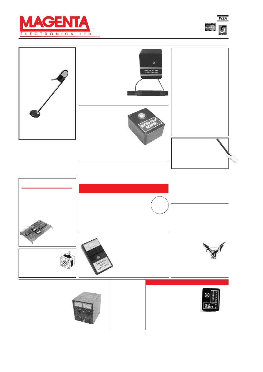
EPE MICROCONTROLLER
P.I. TREASURE HUNTER
The latest MAGENTA DESIGN – highly
stable & sensitive – with I.C. control of all
timing functions and advanced pulse
separation techniques.
) High stability
drift cancelling
) Easy to build
& use
) No ground
effect, works
in seawater
) Detects gold,
silver, ferrous &
non-ferrous
metals
) Efficient quartz controlled
microcontroller pulse generation.
) Full kit with headphones & all
hardware
KIT 847 . . . . . . . . .£63.95
PORTABLE ULTRASONIC
PEsT SCARER
A powerful 23kHz ultrasound generator in a
compact hand-held case. MOSFET output drives
a special sealed transducer with intense pulses
via a special tuned transformer. Sweeping
frequency output is designed to give maximum
output without any special setting up.
KIT 842......................£22.56
Stepping Motors
MD38...Mini 48 step...£8.65
MD35...Std 48 step...£9.99
MD200...200 step...£12.99
MD24...Large 200 step...£22.95
MOSFET MkII VARIABLE BENCH
POWER SUPPLY 0-25V 2·5A
Based on our Mk1 design and
preserving all the features, but
now with switching pre-
regulator for much higher effi-
ciency. Panel meters indicate
Volts and Amps. Fully variable
down to zero. Toroidal mains
transformer.
Kit includes
punched and printed case and
all parts. As featured in April
1994
EPE. An essential piece
of equipment.
Kit No. 845 . . . . . . . .£64.95
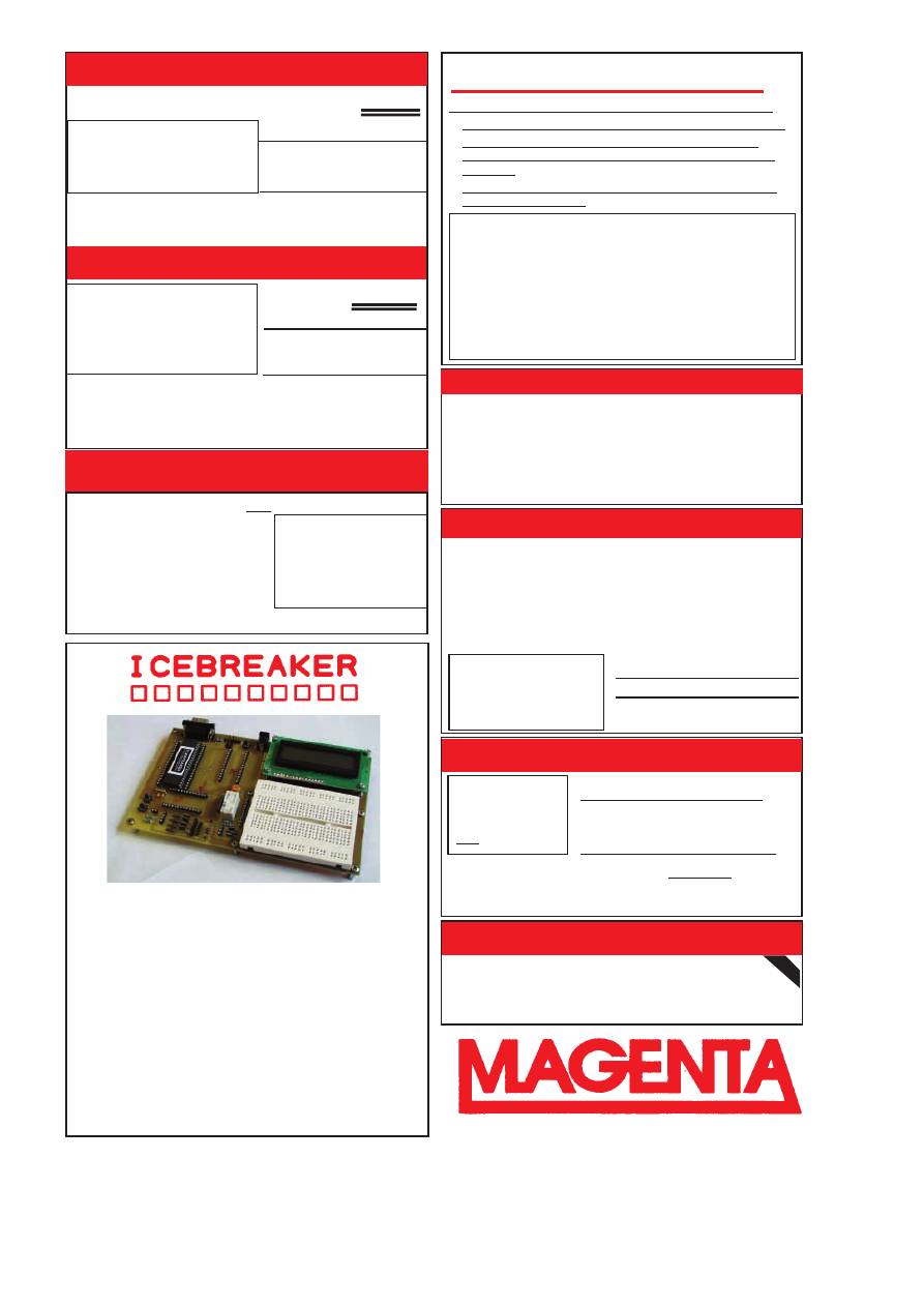
EE222
PIC PIPE DESCALER
)SIMPLE TO BUILD )SWEPT
)HIGH POWER OUTPUT FREQUENCY
)AUDIO & VISUAL MONITORING
An affordable circuit which sweeps
the incoming water supply with
variable frequency electromagnetic
signals. May reduce scale formation,
dissolve existing scale and improve
lathering ability by altering the way
salts in the water behave.
Kit includes case, P.C.B., coupling
coil and all components.
High coil current ensures maximum
effect. L.E.D. monitor.
KIT 868 ....... £22.95
POWER UNIT......£3.99
DUAL OUTPUT TENS UNIT
As featured in March ‘97 issue.
Magenta have prepared a FULL KIT for this.
excellent new project. All components, PCB,
hardware and electrodes are included.
Designed for simple assembly and testing and
providing high level dual output drive.
KIT 866. .
Full kit including four electrodes
£32.90
Set of
4 spare
electrodes
£6.50
1000V & 500V INSULATION
TESTER
Superb new design.
Regulated
output, efficient circuit. Dual-scale
meter, compact case. Reads up to
200 Megohms.
Kit includes wound coil, cut-out
case, meter scale, PCB & ALL
components.
KIT 848. . . . . . . . . . . . £32.95
EPE
PROJECT
PICS
Programmed PICs for
all* EPE Projects
16
C
84/18
F
84/16
C
71
All
£5.90
each
PIC16
F
877 now in stock
£10
inc. VAT & postage
(*some projects are copyright)
E
EP
PE
E
T
TE
EA
AC
CH
H--IIN
N
2
20
00
00
0
Full set of top quality
NEW
components for this educa-
tional series. All parts as
specified by
EPE. Kit includes
breadboard, wire, croc clips,
pins and all components for
experiments, as listed in
introduction to Part 1.
*Batteries and tools not included.
TEACH-IN 2000 -
KIT 879
£44.95
MULTIMETER
£14.45
SPACEWRITER
An innovative and exciting project.
Wave the wand through the air and
your message appears. Programmable
to hold any message up to 16 digits long.
Comes pre-loaded with “MERRY XMAS”. Kit
includes PCB, all components & tube plus
instructions for message loading.
KIT 849 . . . . . . . . . . . .£16.99
SUPER BAT
DETECTOR
1 WATT O/P, BUILT IN
SPEAKER, COMPACT CASE
20kHz-140kHz
NEW DESIGN WITH 40kHz MIC
.
A new circuit using a
‘full-bridge’ audio
amplifier i.c., internal
speaker,
and
headphone/tape socket.
The latest sensitive
transducer, and ‘double
balanced mixer’ give a
stable, high perfor-
mance superheterodyne design.
KIT 861 . . . . . . . . . . .£24.99
ALSO AVAILABLE Built & Tested. . . £39.99
12V EPROM ERASER
A safe low cost eraser for up to 4 EPROMS at a
time in less than 20 minutes. Operates from a
12V supply (400mA). Used extensively for mobile
work - updating equipment in the field etc. Also in
educational situations where mains supplies are
not allowed. Safety interlock prevents contact
with UV.
KIT 790 . . . . . . . . . . . .£29.90
Keep pets/pests away from newly
sown areas, fruit, vegetable and
flower beds, children’s play areas,
patios etc. This project produces
intense pulses of ultrasound which
deter visiting animals.
ULTRASONIC PEsT SCARER
)
UP TO 4 METRES
RANGE
)
LOW CURRENT
DRAIN
)
KIT INCLUDES ALL
COMPONENTS, PCB & CASE
)
EFFICIENT 100V
TRANSDUCER OUTPUT
)
COMPLETELY INAUDIBLE
TO HUMANS
KIT 812. . . . . . . . . . . . . . . . . . . . . . . . . . . . . . £15.00
TENS UNIT
88
Everyday Practical Electronics, February 2001
0
0
0
0
NOW
W
ITH PIC16C84
EEPPROM CHIP & SOFTWARE DISK
68000
DEVELOPMENT
TRAINING KIT
KIT 621
£99.95
)
ON BOARD
5V REGULATOR
)
PSU £6.99
)
SERIAL LEAD £3.99
) NEW PCB DESIGN
) 8MHz 68000 16-BIT BUS
) MANUAL AND SOFTWARE
) 2 SERIAL PORTS
) PIT AND I/O PORT OPTIONS
) 12C PORT OPTIONS
) SUPER UPGRADE FROM V1 )18, 28 AND 40-PIN CHIPS
) READ, WRITE, ASSEMBLE & DISASSEMBLE PICS
) SIMPLE POWER SUPPLY OPTIONS 5V-20V
) ALL SWITCHING UNDER SOFTWARE CONTROL
) MAGENTA DESIGNED PCB HAS TERMINAL PINS AND
OSCILLATOR CONNECTIONS FOR ALL CHIPS
) INCLUDES SOFTWARE AND PIC CHIP
KIT 878 . . . £22.99 with 16F84 . . . £29.99 with 16F877
PIC 16C84 DISPLAY DRIVER
INCREDIBLE LOW PRICE! Kit 857 £
£1
12
2..9
99
9
SIMPLE PIC PROGRAMMER
Power Supply £3.99
EXTRA CHIPS:
PIC 16F84 £4.84
INCLUDES 1-PIC16F84 CHIP
SOFTWARE DISK, LEAD
CONNECTOR, PROFESSIONAL
PC BOARD & INSTRUCTIONS
Based on February ’96 EPE. Magenta designed PCB and kit. PCB
with ‘Reset’ switch, Program switch, 5V regulator and test L.E.D.s,
and connection points for access to all A and B port pins.
INCLUDES 1-PIC16F84 WITH
DEMO PROGRAM SOFTWARE
DISK, PCB, INSTRUCTIONS
AND 16-CHARACTER 2-LINE
LCD DISPLAY
Kit 860
£
£1
19
9..9
99
9
Power Supply
£3.99
FULL PROGRAM SOURCE
CODE SUPPLIED – DEVELOP
YOUR OWN APPLICATION!
Another super PIC project from Magenta. Supplied with PCB, industry
standard 2-LINE × 16-character display, data, all components, and
software to include in your own programs. Ideal development base for
meters, terminals, calculators, counters, timers – Just waiting for your
application!
PIC 16F84 MAINS POWER 4-CHANNEL
CONTROLLER & LIGHT CHASER
) WITH PROGRAMMED 16F84 AND DISK WITH
SOURCE CODE IN MPASM
) ZERO VOLT SWITCHING
MULTIPLE CHASE PATTERNS
) OPTO ISOLATED
5 AMP OUTPUTS
) 12 KEYPAD CONTROL
) SPEED/DIMMING POT.
) HARD-FIRED TRIACS
Kit 855
£
£3
39
9..9
95
5
Now features full 4-channel
chaser software on DISK and
pre-programmed PIC16F84
chip. Easily re-programmed
for your own applications.
Software source code is fully
‘commented’ so that it can be
followed easily.
LOTS OF OTHER APPLICATIONS
Tel: 01283 565435 Fax: 01283 546932 E-mail: sales@magenta2000.co.uk
Everyday Practical Electronics, February 2001
89
All prices include VAT. Add £3.00 p&p. Next day £6.99
E
EP
PE
E
P
PIIC
C T
Tu
utto
orriia
all
At last! A Real, Practical, Hands-On Series
)
Learn Programming from scrach using PIC16F84
)
Start by lighting l.e.d.s and do 30 tutorials to
Sound Generation, Data Display, and a Security
System.
)
PIC TUTOR Board with Switches, l.e.d.s, and on
board programmer
PIC TOOLKIT V2
PIC TUTOR BOARD KIT
Includes: PIC16F84 Chip, TOP Quality PCB printed with
Component Layout and all components* (*not ZIF Socket or
Displays). Included with the Magenta Kit is a disk with Test
and Demonstration routines.
KIT 870 .... £27.95, Built & Tested .... £42.95
Optional: Power Supply – £3.99, ZIF Socket – £9.99
LCD Display ........... £7.99 LED Display ............ £6.99
Reprints Mar/Apr/May 98 – £3.00 set 3
SUPER PIC PROGRAMMER
)
READS, PROGRAMS, AND VERIFIES
) WINDOWSK SOFTWARE
) PIC16C6X, 7X, AND 8X
) USES ANY PC PARALLEL PORT
) USES STANDARD MICROCHIP )HEX FILES
) OPTIONAL DISASSEMBLER SOFTWARE (EXTRA)
) PCB, LEAD, ALL COMPONENTS, TURNED-PIN
SOCKETS FOR 18, 28, AND 40 PIN ICs
) SEND FOR DETAILED
INFORMATION – A
SUPERB PRODUCT AT
AN UNBEATABLE LOW
PRICE.
Kit 862
£
£2
29
9..9
99
9
Power Supply £3.99
DISASSEMBLER
SOFTWARE
£11.75
PIC STEPPING MOTOR DRIVER
8-CHANNEL DATA LOGGER
INCLUDES PCB,
PIC16F84 WITH
DEMO PROGRAM,
SOFTWARE DISC,
INSTRUCTIONS
AND MOTOR.
Kit 863
£
£1
18
8..9
99
9
FULL SOURCE CODE SUPPLIED
ALSO USE FOR DRIVING OTHER
POWER DEVICES e.g. SOLENOIDS
Another NEW Magenta PIC project. Drives any 4-phase unipolar motor – up
to 24V and 1A. Kit includes all components and 48 step motor. Chip is
pre-programmed with demo software, then write your own, and re-program
the same chip! Circuit accepts inputs from switches etc and drives motor in
response. Also runs standard demo sequence from memory.
As featured in Aug./Sept. ’99
EPE. Full kit with Magenta
redesigned PCB – LCD fits directly on board. Use as Data
Logger
or as a test bed for many other 16F877 projects. Kit
includes programmed chip, 8 EEPROMs, PCB, case and all components.
KIT 877 £49.95
inc. 8 × 256K EEPROMS
NEW!
PIC Real Time
In-Circuit Emulator
* Icebreaker uses PIC16F877 in circuit debugger
* Links to Standard PC Serial Port (lead supplied)
* Windows
TM
(95+) Software included
* Works with MPASM and MPLAB Microchip software
* 16 x 2 L.C.D., Breadboard, Relay, I/O devices and patch leads supplied
As featured in March ’00
EPE. Ideal for beginners AND advanced users.
Programs can be written, assembled, downloaded into the microcontroller and run at full
speed (up to 20MHz), or one step at a time.
Full emulation means that all I/O ports respond exactly and immediately, reading and
driving external hardware.
Features include: Reset; Halt on external pulse; Set Breakpoint; Examine and Change
registers, EEPROM and program memory; Load program, Single Step with display of
Status, W register, Program counter, and user selected ‘Watch Window’ registers.
KIT 900 . . . £34.99
POWER SUPPLY
£3.99
STEPPING MOTOR
£5.99

'LDF
'%9
7UDQVLVWRUV
1
1
1$
1$
1$
1
1$
1$
1$
1
1
1
1
1
1
1
1
1
1
1
1
1
1
1
1
1
1
1
1
1
1
1
1
6%
$&
$&
$&
$&
$&<
$'
$'
$'
%&
%&%
%&
%&%
%&&
%&
%&&
%&
%&
%&
%&
%&
%&
%&
%&
%&
%&
%&
%&
%&
%&
%&%
%&%
%&%
%&
%&
%&
%&
%&/
%&/
%&
%&/
%&&
%&%
%&
%&$
%&
%&/
%&%
%&/&
%&
%&/
%&
%&%
%&%
%&&
%&$
%&
%&%
%&%
%&%
%&
%&
%&&
%&
%&
%&
%&
%&
%&%
%&
%&
%&
%&
%&
%&
%&
%&
%&
%&
%&
%&%
%&&
%&$
%&%
%&&
%&&
%&%
%&&
%&&
%&$
%&$
%&%
%&&
%&%
%&%
%&$
%&%
%&
%&
%&
%&
%&<
%&<
%&<
%'3
%'
%'
%'
%'
%'
%'
%'
%'&
%'
%'
%'
%'
%'
%'
%'&
%'&
%'&
%'
%'
%'
%'
%'
%'
%'
%'
%'
%'
%'
%'
%';
%';&
%';&
%';&
%';&
%)
%)
%)
%)
%)%
%)
%)
%)%
%)&
%)
%)
%)
%)
%)
%)
%)
%);
%);
%);
%)<
%)<
%)<
%6
%6
%8$
%8$
%8
%8$
%8'
%8
%87$
%87$)
%8;
,5)
,5)
,5)
0-
0-
0-
0-
0-(
0-(
036$
036$
036$
036$
7,3$
7,3&
7,3$
7,3&
7,3$
7,3&
7,3$
7,3&
7,3&
7,3$
7,3&
7,3$
7,3&
7,3
7,3
7,3
7,3
7,3
7,3
7,3
7,3
7,3
7,3
7,3
7,3
7,3
7,3
7,3
=7;
=7;
=7;
=7;
=7;
=7;
=7;
=7;
=7;
=7;
=7;%
=7;
=7;
=7;
=7;%
=7;%
=7;
=7;
=7;
=7;
=7;$
=7;$
=7;
=7;
=7;
=7;$
=7;$
=7;$
(OHFWURO\WLF5DGLDO
µF 16v 25v 40v 63v 100v
0.47
--- --- --- £0.05
---
1.0 --- --- --- £0.05
£0.05
2.2 --- --- --- £0.05
---
4.7 --- --- £0.05
£0.05
£0.06
10
£0.05 £0.05 £0.05 £0.05 £0.09
22
£0.05 £0.05 £0.05 £0.07 £0.11
33
£0.05 ---
£0.05 ---
---
47
£0.05 £0.05 £0.08 £0.11 £0.19
100 £0.07 £0.08 £0.10 £0.13 £0.26
220 £0.09 £0.09 £0.13 £0.28 ---
330 £0.09 ---
£0.19 ---
---
470 £0.13 £0.17 £0.24 £0.33 ---
1000 £0.21 £0.33 £0.34 £0.84 ---
2200 £0.32 £0.55 £0.70 ---
---
3300
--- £0.94
--- --- ---
4700 £0.67 £1.05 ---
---
---
(OHFWURO\WLF$[LDO
16v 25v 40v 63v 100v
250v
450v
--- --- --- --- --- --- ---
--- --- --- £0.13
--- --- £0.22
--- --- --- £0.13
--- --- £0.30
--- --- --- £0.13
--- --- £0.41
£0.12 ---
£0.12 £0.13 £0.17 £0.40 £0.67
£0.12 £0.13 £0.14 £0.15 £0.21 £0.52 £1.06
--- --- --- --- --- --- ---
£0.13 £0.13 £0.15 £0.19 £0.32 £0.57 ---
£0.14 £0.16 £0.19 £0.26 £0.44 ---
---
£0.19 £0.20 £0.25 £0.39 £0.48 ---
---
--- --- --- --- --- --- ---
£0.24 £0.28 £0.41 £0.53 ---
---
---
£0.33 £0.43 £0.59 £1.08 ---
---
---
£0.53 £0.69 £1.18 £1.55 ---
---
---
--- --- --- --- --- --- ---
£0.86
£1.11
--- --- --- --- ---
7ULDFV
%7
%7
%7
%7
%7
%7
%7$%
%7$
%:
%7$&
%7$
6:
%7$
%:
%7$
&:
%7$%
%7$%
7,&'
7,&0
7,&'
7,&0
7,&'
7,&0
7,&'
=2'$
7K\ULVWRUV
&'
32$$
7,&'
7,&'
%ULGJH5HFWLILHUV
$9
$9
$9
$9
$9
$N9
$9
$9
$9
$9
$9
$9
$9
$9
%<
%<
%<
2$
2$
2$
2$
2$
8)
8)
8)
8)
8)
8)
8)
=HQHUVWR9
P:
:
'LRGHV
1
1
1
1
1
1
1
1
1
1
1
1
1
1
1
1
1
1
$
$
$
$
$
$
$
%$
%$
%$
%$7
%$7
%$7
%$7
%$7
%$9
%$:
%$;
%$;
9ROWDJH
5HJXODWRUV
/
/
/
/
/
/
6
6
6
/
/
/
/
$'0$1
/&9
/
/$
/0&7
/0/=
/07
/0.
/0.
/0=
/07
/0.
/07
/0
/3&=
5()&3
5()&3
5()=
5()*3
5()=
5()=
7/&3
=5
=1%
$'&RQYHUWHUV
'DWD$FTXLVLWLRQ
$'$1
$'-1
$'-1
$'$.1
$'.1
'$&
,&/&3/
7/&,3
=1(
5$0
*0&
+0
+7
8$'&
.0
(3520ªV
&
&
&
&
&
&
&
/LQHDU,&V
$'$'
$'-1
$'-+
$'$1
$'$4
$'$1
$'-1
$'-1
$'-1
$'-1
$'-1
$'-1
$'-1
$'-1
$'$1
$'1
$'$1
$'$1
$'$1
$'$1
$'-1
$'$1
$'-1
$'.1
$'(/$
$'0$+
$'0$$
$'0-1
$'0$1
$'0$1
$'0$1
$'0$1
&$&(
&$&(
&$
&$
&$(
&$(
&$(
&$(
&$(
'*&-
'*'-
,&/&3/
,&/&3/
,&/&/3
,&/'&3
,&/
,&/6&3
,&/
,&0
,&0
/
/0
/(
/
/1
/
/)1
/)1
/)1
/)
/0$1
/01
/01
/0
/01
/0
/0=
/01
/01
/01
/01
/01
/0
/01
/01
/0&1
/0
/01
/01
/0
/0
/0
/0&&1
/0&,1
/31
/31
/31
/7&1
0$;&3(
0$;&1
0$;&3(
0$;&3(
0$;&3(
0$;&3
0$;&3
0$;$&3
0$;$&3
0$;&3
0&1
0&
0&
0&
0&3
0&3
09'3
1(1
1(1
1(1
1(1
1(1
1(1
1(1
1(
1(1
1(1
1(1
23&1
23&1
23*3
23*3
23)3
23*3
23*3
23*3
23*3
23)3
23*3
23*3
23*3
23*3
23*3
23*3
23*3
5&
6*1
6*
6603
6603
6603
6603
7%$6
7%$
7%$6
7%$0
7'$6
7'$
7'$
7'$9
7'$$
7'$$
7'$$
7(''3
7($
7/&3
7/&3
7/&1
7/&3
7/&1
7/&1
7/
7/&1
7/&1
7/&1
7/$&3
7/&
7/&
76&1
703)3
8/1
8/1$
8/1
8/1$
;5
/66HULHV
/6
/6
/6
/6
/6
/6
/6
/6
/6
/6
/6
/6
/6
/6
/6
/6
/6
/6
/6
/6
/6
/6
/6
/6
/6
/6
/6
/6
/6
/6
/6
/6
/6
/6
/6
/6
/6
/6
/6
/6
/6
/6
/6
/6
/6
/6
/6
/6
/6
/6
/6
/6
/6
/6
/6
/6
/6
/6
/6
/6
/6
/6
/6
/6
/6
/6
/6
/6
/6
/6
/6
/6
/6
/6
/6
/6
/6
/6
/6
/6
/6
/6
/6
/6
/6
/6
/6
/6
/6
/6
/6
/6
/6
/6
/6
/6
+&6HULHV
+&
+&
+&
+&
+&
+&
+&
+&
+&
+&
+&
+&
+&
+&
+&
+&
+&
+&
+&
+&
+&
+&
+&
+&
+&
+&
+&
+&
+&
+&
+&
+&
+&
+&
+&
+&
+&
+&
+&
+&
+&
+&
+&
+&
+&
+&
+&
+&
+&
+&
+&
+&
+&
+&
+&
+&
+&
+&
+&
+&
+&
+&
+&
+&
+&
+&
+&
+&
+&
+&
+&
+&
+&
+&
+&
+&
+&
+&
+&
+&
+&
+&
+&
6HULHV
%
%
%
%
8%
%
8%
%
%
%
%
%
%
%
%
%
%
%
%
%
%
%
%
%
%
%
%
%
%
%
%
%
%
%
%
%
%
%
8%
%
%
%
%
%
%
%
%
%
%
%
8%
%
%
%
%
%
%
%
%
%
%
%
%
%
%
%
%
%
%
%
%
%
%
%
%
%
%
%
%
%
%
%
%
%
%
%
%
%
%
%
%
%
%
%
%
%
%
%
%
%
6HH
1H[W
/DVW
0
R
QWK
V
$G
IRU
&20321(17
$
&&(6625
,(6
7HO )D[
&RQWUROOHUV
$7&
&$3
&$3
&$3
&-:
&3
)3
)3
3+21()2527+(5'(9,&(6
48$17,7<',6&28176
3ULFHV ([FOXGH 9DW #ã $GG 8.
FDUULDJH9DWWRDOORUGHUV&KHTXHV3RVWDO
RUGHUVSD\DEOHWR(65(OHFWURQLF&RPSRQHQWV
(PDLOVDOHV#HVUFRXN KWWSZZZHVUFRXN
SOLO
6WDWLRQ5RDG&XOOHUFRDWV
7\QH:HDU1(34
6WDWLRQ5RDG&XOOHUFRDWV
7\QH:HDU1(34
$OO0DMRU&UHGLWFDUGV$FFHSWHG
1R0LQLPXP
2UGHU9DOXH
6$0('$<
'(63$7&+
6HULHV
SHURIRQHYDOXHRQO\
5HVLVWRUV3OHDVH6WDWH9DOXH5HTXLUHG
:&DUERQ)LOP
(6HULHV
Ω
0
(DFK SHU
ä:&DUERQ)LOP
(6HULHV
Ω
0
(DFK SHU
ä:0HWDO)LOP
(6HULHV
Ω
0
(DFK SHU
ã:&DUERQ)LOP
(6HULHV
Ω
0
(DFK SHU
::LUHZRXQG
(6HULHV
Ω
Ω
(DFK
:::DOVRLQVWRFNVHOHFWHGYDOXHVRQO\FRQWDFWVDOHVGHSWIRUGHWDLOV
3UHVHW5HVLVWRUV3OHDVH6WDWH9DOXH5HTXLUHG
(QFORVHGPP6TXDUH+RU]9HUW
Ω
0:
(DFK
6NHOHWRQPP'LD+RUL]RQWDO
Ω
0:
(DFK
6XEPLQPP'LD+RUL]RQWDO
(
Ω
0:
(DFK
0XOWLWXUQPP6TXDUH7RS$GMXVW (
Ω
0:
(DFK
0XOWLWXUQPP/RQJ(QG$GMXVW
(
Ω
0:
(DFK
3RWHQWLRPHWHUV3OHDVH6WDWH9DOXH5HTXLUHG
6LQJOH*DQJä¨6KDIWPP'LD
Ω
0/LQHDU
(DFK
6LQJOH*DQJä¨6KDIWPP'LDNNNN00/RJ (DFK
'XDO*DQJ ä¨6KDIWPP'LD
N0/LQHDU
(DFK
'XDO*DQJ ä¨6KDIWPP'LD
N0/RJDULWKPLF
(DFK
6ZLWFKHG ä¨6KDIWPP'LD
N0/LQHDU
(DFK
6ZLWFKHG ä¨6KDIWPP'LD
N0/RJDULWKPLF
(DFK
3&%0RXQW6SOLQHG6KDIWPP'LD
Ω
0/LQHDU
(DFK
3&%0RXQW6SOLQHG6KDIWPP'LD
Ω
NN0/RJ (DFK
'XDO3&%6SOLQHG6KDIWPP'LD NNNN/LQ
(DFK
'XDO3&%6SOLQHG6KDIWPP'LD NNNN/RJ (DFK
7HDFKLQ(3(3URMHFWV
+DUGZDUH7RROV3DFN
1RUPDO
3DFN3ULFH
&RPSRQHQWV3DFN
1RUPDO
3DFN3ULFH
&RPSRQHQWV3DFN
1RUPDO
3DFN3ULFH
)XOOGHWDLOVRQRXU:HEVLWH

Editorial Offices:
EVERYDAY PRACTICAL ELECTRONICS EDITORIAL
ALLEN HOUSE, EAST BOROUGH, WIMBORNE
DORSET BH21 1PF
Phone: Wimborne (01202) 881749
Fax: (01202) 841692.
E-mail: editorial@epemag.wimborne.co.uk
Web Site: http://www.epemag.wimborne.co.uk
EPE Online
www.epemag.com
See notes on Readers’ Enquiries below – we regret lengthy
technical enquiries cannot be answered over the telephone.
Advertisement Offices:
EVERYDAY PRACTICAL ELECTRONICS ADVERTISEMENTS
MILL LODGE, MILL LANE
THORPE-LE-SOKEN, ESSEX CO16 0ED
Phone/Fax: (01255) 861161
Editor: MIKE KENWARD
Deputy Editor: DAVID BARRINGTON
Technical Editor: JOHN BECKER
Business Manager: DAVID J. LEAVER
Subscriptions: MARILYN GOLDBERG
Administration: FAY KENWARD
Editorial/Admin: Wimborne (01202) 881749
Advertisement Manager:
PETER J. MEW, Frinton (01255) 861161
Advertisement Copy Controller:
PETER SHERIDAN, Wimborne (01202) 882299
On-Line Editor: ALAN WINSTANLEY
EPE Online (Internet version) Editors:
CLIVE (MAX) MAXFIELD and ALVIN BROWN
READERS’ ENQUIRIES
E-mail: techdept@epemag.wimborne.co.uk
We are unable to offer any advice on the use,
purchase, repair or modification of commercial
equipment or the incorporation or modification
of designs published in the magazine. We
regret that we cannot provide data or answer
queries on articles or projects that are more
than five years old. Letters requiring a personal
reply
must be accompanied by a stamped
self-addressed envelope or a self-
addressed envelope and international reply
coupons. All reasonable precautions are
taken to ensure that the advice and data given
to readers is reliable. We cannot, however,
guarantee it and we cannot accept legal
responsibility for it.
COMPONENT SUPPLIES
We do not supply electronic components or
kits for building the projects featured, these
can be supplied by advertisers (see
Shoptalk).
We advise readers to check that all parts are
still available before commencing any project
in a back-dated issue.
ADVERTISEMENTS
E-mail: adverts@epemag.wimborne.co.uk
Although the proprietors and staff of
EVERYDAY PRACTICAL ELECTRONICS take
reasonable precautions to protect the interests
of readers by ensuring as far as practicable
that advertisements are
bona fide, the maga-
zine and its Publishers cannot give any under-
takings in respect of statements or claims
made by advertisers, whether these advertise-
ments are printed as part of the magazine, or
in inserts.
The Publishers regret that under no circum-
stances will the magazine accept liability for
non-receipt of goods ordered, or for late
delivery, or for faults in manufacture.
TRANSMITTERS/BUGS/TELEPHONE
EQUIPMENT
We advise readers that certain items of radio
transmitting and telephone equipment which
may be advertised in our pages cannot be
legally used in the UK. Readers should check
the law before buying any transmitting or
telephone equipment as a fine, confiscation of
equipment and/or imprisonment can result
from illegal use or ownership. The laws vary
from country to country; readers should check
local laws.
AVAILABILITY
Copies of
EPE
are available on subscription anywhere
in the world (see below), from all UK newsagents
(distributed by COMAG) and from the following
electronic component retailers: Omni Electronics and
Yebo Electronics (S. Africa).
EPE
can also be pur-
chased from retail magazine outlets around the world.
An Internet on-line version can be purchased for just
$9.99(US) per year available from www.epemag.com
SUBSCRIPTIONS
Subscriptions for delivery direct to any address in the
UK: 6 months £14.50, 12 months £27.50, two years
£50; Overseas: 6 months £17.50 standard air service or
£27 express airmail, 12 months £33.50 standard air ser-
vice or £51 express airmail, 24 months £62 standard air
service or £97 express airmail.
Online subscriptions, for downloading the magazine via
the Internet, $9.99(US) for one year available from
www.epemag.com.
Cheques or bank drafts (in £ sterling only) payable to
Everyday Practical Electronics
and sent to EPE Sub.
Dept., Allen House, East Borough, Wimborne, Dorset
BH21 1PF. Tel: 01202 881749. Fax: 01202 841692. E-
mail: subs@epemag.wimborne.co.uk. Also via the Web
at: http://www.epemag.wimborne.co.uk. Subscriptions
start with the next available issue. We accept
MasterCard, Switch or Visa. (For past issues see the
Back Issues
page
.)
BINDERS
Binders to hold one volume (12 issues) are available
from the above address. These are finished in blue
p.v.c., printed with the magazine logo in gold on the
spine. Price £5.95 plus £3.50 p&p (for overseas readers
the postage is £6.00 to everywhere except Australia
and Papua New Guinea which cost £10.50).
Normally
sent within seven days but please allow 28 days for
delivery – more for overseas.
Payment in £ sterling only please. Visa, Switch and
MasterCard accepted, minimum credit card order
£5. Send, fax or phone your card number and card
expiry date with your name, address etc. Or order
on our secure server via our UK web site. Overseas
customers – your credit card will be charged by the
card provider in your local currency at the existing
exchange rate.
Everyday Practical Electronics, February 2001
91
VOL. 30 No. 2 FEBRUARY 2001
SOMETHING SOGGY
I asked Marilyn what I should write my Editorial about this month; as she
was gazing out of the window at the level of the River Allen just a few feet
from my office, her reply was “Something soggy’’. Despite the flood protec-
tion wall (built through Wimborne at great expense a few years ago), our small
office garden was awash because the water table was so high and the river just
a foot or so from the top of the wall and our office floor level. At least at the
time it had stopped raining – probably only for a day or so – and the water level
was receding.
What has all this got to do with technology? Well, nothing really, and that is
the point. Whilst we can monitor the water levels and the weather with all
means of high tech gubbins, we can’t do anything about changing it. We have
satellites and the Internet, we have mind-boggling electro-mechanical data
storage (see the Millipede News item last month), we can generate massive
amounts of power by all sorts of means, but we still fail to protect ourselves
and our homes from the effects of the elements. Our world is far more power-
ful than we are, and it will no doubt remain so.
COMMERCIAL
Of course, we live in a commercial world where profit rules – if someone
could make money from flood protection, like they can from communications,
then we would soon see more barriers, pumps and pipes to protect vulnerable
areas. Sadly, at present this is not the case, but maybe insurance companies and
their regularly flooded customers could make schemes viable in the future.
With, of course, electronics to monitor and control the systems.
There are few bounds to what we can achieve – as electronics developments
continue to prove – if it is financially worthwhile. We are, however, still limit-
ed to what we can achieve when the elements decide to be nasty. However, next
month we intend to show you how to generate your own lightning – see
page 83.

CCoonnssttrruuccttiioonnaall PPrroojjeecctt
T
HIS
project gives an indication of the
outside temperature by the changing
appearance of a three-colour light-
emitting diode (l.e.d.). Above a certain
threshold (nominally 6°C), it will be off.
As the temperature falls, it will progres-
sively appear Green (below 6°C), Yellow
(below 4°C) and Red (below 2°C). These
operating points could be changed over a
small range to suit the application.
The Ice Alert will be found particularly
useful by car drivers. However, readers
will find many other applications for it. For
example, gardeners could use it to monitor
the temperature inside a greenhouse or at
the ground surface from a point inside the
house.
EARLY WARNING
In many situations, the actual tempera-
ture of the surroundings does not need to
be known. It is sufficient to be aware of it
falling towards freezing point (0°C). When
driving a car, steps may then be taken to
reduce speed and be alert to the possibility
of icy patches developing on the road.
When used in a car, the Ice Alert must
not be relied on by the driver or used as a
substitute for normal vigilance. It is
designed simply to provide additional
information which may assist safe
driving.
Experienced motorists know that there
may be isolated frosty patches even when
the general temperature is several degrees
above freezing point. Since the sensor
takes a few minutes to respond, isolated
regions having a lower temperature may
not be “seen’’.
APPEARANCE
The circuit is built in a small plastic box.
On the front panel a 3mm tri-colour l.e.d.
shows through a small hole (see photo-
graph). A temperature sensor is connected
through a length of twin wire to a piece of
screw terminal block on the circuit board.
Depending on the application, the sen-
sor will need to be protected against
mechanical damage and weatherproofed.
For automotive use, it will be attached to a
suitable place underneath the car.
When installed in a car, the inter-con-
necting lead will be fairly short. However,
for other purposes it might be considerably
longer. The system was used successfully
with a lead 10m (33ft. approx.) in length. It
could probably be made longer than this
but the constructor would need to make the
necessary tests.
THERMAL CHECK
It may be possible to set up the circuit
without calibration using common sense
methods but this is not advised. For best
results you will need to use a good quality
laboratory-type thermometer capable of
reading over the range 0°C to 10°C with an
accuracy of 0·5°C.
Beware of inexpensive digital ther-
mometers whose good resolution (say,
0·1°C) may deceive the user into thinking
that they must be accurate. The author’s
was “out’’ by almost 1·5°C.
Calibration does not take long and it
may be possible to borrow a suitable ther-
mometer from a local school or college for
an hour or two. Note that a photographic
thermometer is not suitable because its
scale often starts at 15°C.
POWERING UP
When used in the car, the circuit
receives current through the ignition
switch so, while left unattended, no current
is drawn. With the ignition on, the current
required by the prototype unit is between
7mA (with no colour showing) and 40mA
with yellow. Such a low value imposes
very little load on the charging system.
If the circuit is to be used for other than
car purposes, it may be operated from a 9V
battery (for example, the PP3 type) which
can be accommodated inside the unit.
When using such a supply, it will be nec-
essary to include a pushbutton switch to
power-up the circuit only when required.
The current drawn will be less than that
stated above for a 12V supply but, even so,
continuous operation will soon drain the
battery.
CIRCUIT DESCRIPTION
The complete circuit diagram for the
Ice Alert is shown in Fig.1. The tempera-
ture sensor consists of miniature bead
thermistor, R1. This relatively simple,
small and inexpensive device proved to
have several advantages over temperature
sensing i.c.s.
Note that the thermistor should be of the
specified type if the circuit is to work with-
out modification. Other types of thermistor
could be used but the user may need to
experiment with component values. More
will be said about this later.
Ignore capacitor Cl for the moment. The
thermistor R1 is connected in series with
fixed resistor R2. This forms a potential
divider connected across Zener diode D1.
The Zener diode operates in conjunction
with resistor R4 to provide a fixed 5·1V
(nominal) supply.
ICE
ALERT
Red alert for a frost warning!
92
Everyday Practical Electronics, February 2001
TERRY de VAUX-BALBIRNIE
Completed Ice Alert. The small square of Velcro enables it to be easily installed
below a vehicle dashboard.
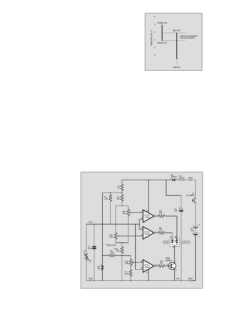
As the battery voltage rises or falls, the
voltage appearing across resistor R4 will
be the difference between that of the sup-
ply and the Zener breakdown voltage. Of
course, the supply will need to exceed 5·1V
for this to happen.
RISING VOLTAGE
As the temperature falls, the resistance
of thermistor R1 increases and so does the
voltage across it. At the operating tempera-
tures (6°C, 4°C and 2°C), the voltages will
be some 2·8V, 3·95V and 3·1V respective-
ly. Note that these figures are approximate
and are given only for the purpose of
illustration.
By sensing the voltage across the ther-
mistor, the tri-colour l.e.d., D2, may be
made to operate at the correct tempera-
tures. From now on, 6°C is referred to as
the “upper fixed point’’, 4°C the “interme-
diate fixed point’’ and 2°C the “lower fixed
point’’.
In operation, only a few microamps flow
through thermistor R1. Its power dissipa-
tion is therefore only a matter of
microwatts and this results in very low self-
heating. Its ability to measure temperature
is therefore hardly affected by the heating
effect of the current.
Capacitor Cl is connected in parallel
with the thermistor. If the sensor connect-
ing lead is fairly long, it tends to pick up
“hum’’ from a.c. power fields and this
could cause the l.e.d.s to flicker near the
operating points. The capacitor bypasses
the a.c. while having no effect on the stand-
ing d.c. voltage. This allows the l.e.d.s to
switch more smoothly.
SMALL CHANGE
Integrated circuit IC1 is a quad opera-
tional amplifier (op.amp). This means that
it contains four identical units contained in
a single 14-pin package. Only three of the
sections (ICla, IC1b and IC1c) are actually
used. The unused op.amp is “grounded’’ on
the circuit board.
The inverting input of IC1a (pin 2), the
non-inverting input of IC1b (pin 5) and
the non-inverting input of IC1c (pin 12)
are connected together and these, in
turn, are connected to the top end of
thermistor R1.
When the temperature of the thermistor
is high, the voltage between these inputs
and the 0V line will be low. When the tem-
perature is low, the voltage here will be rel-
atively high.
The remaining op.amp inputs (IC1a
non-inverting input pin 3, IC1b inverting
input pin 6 and IC1c inverting input pin 13)
are connected to the sliding contacts of
preset potentiometers VR2, VR1 and VR3
respectively. These provide adjustments to
the operating points. The specified devices
are multiturn trimmers which makes for
very easy, accurate and convenient adjust-
ment at the setting-up stage.
The ends of VR1 and VR2 tracks are
connected in parallel and share fixed resis-
tors R5 and R6 to form potential divider
arrangements. The whole network is con-
nected across D1, the 5·1V Zener stabilised
supply. The fixed resistors limit the range
of voltage available at the sliding contacts
between some 2·5V and 3·6V.
With the specified thermistor this corre-
sponds to a change from –5°C to +12°C
approximately. This easily covers the range
of temperatures over which the device is
likely to be used.
Preset potentiometer VR3 works in a
similar way to VR1 and VR2 but it has its
own pair of resistors R3 and R7 to form a
potential divider. The range of voltage
available is 2·2V to 3·3V and this corre-
sponds to a change from –1°C to +18°C
approximately.
Stabilising the voltage applied to the
potential dividers gives a precision effect
and helps to maintain operating accuracy.
INPUT CONDITIONS
Look at IC1c first. Preset VR3 will be
adjusted so that when the temperature
sensed by the thermistor is 6°C (the upper
fixed point) or less, the non-inverting input
(pin 12) voltage will exceed the inverting
one (pin 13).
Under these conditions, the output at pin
14 will be high and current will flow
through current-limiting resistor R10 into
the base (b) of transistor TR1. This turns it
on and the collector (c) goes low. The l.e.d.
(D2) is now enabled because there is a con-
ducting path from the common cathode (k)
to the 0V line.
When a higher temperature than the
upper fixed point is detected, the input
conditions are reversed and IC1 pin 14 will
be low. With TR1 off, the conducting path
is removed and the l.e.d. will not operate. A
full description of how the tri-colour l.e.d.
works is given later.
Preset VR2 is adjusted so that the volt-
age at IC1a non-inverting input (pin 3) is
more than that at the inverting one (pin
2) for temperatures above 2°C (the lower
fixed point). During this period, pin 1 is
high and current can flow through cur-
rent-limiting resistor R8 and the green
l.e.d. section. Green will, therefore, show
between the upper and lower fixed
points.
Preset VR1 will be adjusted so that the
inverting input voltage of IC1b (pin 6) is
less than that at the non-inverting one (pin
5) below 4°C (the intermediate fixed
point). During this time, pin 7 will be high
and the red l.e.d. section operates through
current-limiting resistor R9. Red will show
with temperatures below the intermediate
fixed point.
This is best illustrated with the diagram
shown in Fig. 2. The overall effect is that
nothing will happen above the upper fixed
point (because the l.e.d. is disabled), green
will show down to the intermediate fixed
point, yellow down to the lower fixed point
(because both l.e.d. sections are on) and
red below the lower fixed point (because
the green section goes off).
COLOURFUL
DESCRIPTION
For those who are not familiar with the
tri-colour l.e.d., a brief description follows.
Unlike a conventional l.e.d. this has three
pinout leads – not two. The centre one is
the common cathode (k) and is connected
Everyday Practical Electronics, February 2001
93
Fig.2. Tri-colour l.e.d. switching levels.
Ω
Ω
µ
Fig.1. Complete circuit diagram for the Ice Alert.

to 0V. The other leads are the anodes of
separate red and green l.e.ds. (ar and ag
respectively) contained within a white
translucent plastic package.
With current flowing through the red
section only, the effect will obviously be
red. Similarly, when current flows through
the green section only, the effect will be
green.
However, if both l.e.d. sections pass cur-
rent, the red and green light diffuse and
mix in the milky white plastic body to give
a “yellow’’. Any student of physics will
know that red light (a primary colour)
mixed with green light (a primary colour)
gives the secondary colour, yellow. Note
that this is not the same as mixing red and
green paint!
PROTECTION
A supply is connected to the circuit
through on-off switch S1 (if powered using
an internal battery), fuse FS1 and diode
D3. This latter component provides
reverse-polarity protection. Thus, if the
supply were to be connected in the oppo-
site sense, the diode would fail to conduct
and nothing would happen.
Fuse FS1 will blow if the current rises
excessively in the event of a short-circuit.
This is vital when a car battery is used
because these can deliver an enormous cur-
rent under short-circuit conditions. This
could melt p.c.b. tracks, cause burns and be
a general fire hazard.
Since the car charging circuit provides
a rather unsmooth output, capacitor C2
is included to condition it and provide
a suitable supply for the rest of the
circuit.
CONSTRUCTION
Construction is based on a single-sided
printed circuit board (p.c.b.). The topside
component layout and full-size underside
copper foil track master are shown in Fig.3.
This board is available from the EPE PCB
Service, code 287.
All components, apart from the thermis-
tor (R1) and on-off switch S1 (if used) are
mounted on the p.c.b. Begin construction
by drilling the two fixing holes and solder-
ing the link wire in place as indicated. Note
that this is difficult to do after preset VR2
has been soldered in position.
Add the pieces of screw terminal block,
the 14-pin d.i.l. socket for IC1 (but do not
insert the i.c. itself yet) and the fuse clips.
If fuse clips such as those shown in the
photograph are not available, use a p.c.b.
mounting fuseholder or a small fuseholder
mounted off-board.
Solder all fixed resistors and capacitor
C1 in position. Note that if a 9V battery
is to be used as the power supply, resis-
tors R8 and R9 could be reduced to 330
ohms if the l.e.d. does not turn out to be
bright enough in use. In the interests of
long battery life, however, leave them as
they are.
To make up the specified value for
resistor R6, you could use a l00k (kilo-
hms) and a 10k unit connected in series
(as in the prototype unit). Add capacitor
C2 and diodes D1 and D3 taking care
over the polarity of these components.
The orientation of D1 is correct as
shown.
To the beginner, it may seem as if it is
the wrong way round. However, because it
is a Zener diode it operates in reverse bias.
The negative lead of C2 is clearly indicat-
ed and is slightly shorter than the positive
one.
Next, solder the preset potentiometers
in place. These should be mounted as
shown in Fig.3 and the photograph (with
the adjustment screw on VR1 and VR2 at
top right and for VR3 bottom right). The
circuit will work if they are mounted in
the opposite sense but the instructions
given later regarding their adjustment
will be incorrect and the effect might be
confusing. Note that the preset poten-
tiometers should be of the type having a
top adjustment screw and with the pins in
line (rather than in the form of a
triangle).
TRI-COLOUR L.E.D.
Now look at the tri-colour l.e.d. (D2).
The common cathode (k) lead is the centre
one and the red and green anode (ar and ag
respectively) are on each side of it. It is
important to solder this device with the
anode leads located correctly. If they are
incorrectly placed, the colours will be
interchanged and this would give strange
results at the setting-up stage.
The longer of the two anode leads is the
red and the shorter one green, see inset dia-
gram in Fig.3. After taking note of which is
which, cut them to a length of 10mm, bend
them carefully through right angles and
solder them in position.
If you lose track of which lead is which,
the specified unit is different in the way the
end leads enter the body. If you look care-
fully, you will see that the red one is bent
though a right angle whereas the green one
makes an obtuse angle.
Adjust the preset potentiometers in the
following way (assuming they are of the
specified pattern and have been mounted as
indicated in Fig.3): VR1 and VR2 fully
clockwise and VR3 full anti-clockwise.
Note that these devices usually click if the
screw continues to be turned after the slid-
ing contact has reached the ends of its
track.
Finally, place a 200mA quick-blow fuse
between the fuse clips and insert IC1 into
its socket taking care over the orientation.
TESTING
Do not test the unit by immersing the
thermistor in water. This is because tap
water is a reasonably good conductor of
electricity and it would effectively short-
circuit the leads. This would give an
apparent reduction in the resistance of
the thermistor and lead to totally incor-
rect results.
Do not wait until the thermistor has been
waterproofed or the slower response time
would make calibration inconvenient.
The circuit should be tested and adjusted
using a 9V battery (an alkaline PP3 type
would be suitable). This should be done
before mounting the p.c.b. in its case. In
this way, any small faults may be corrected
more conveniently.
Since water must be avoided for the rea-
son stated above, use cooking oil for cali-
bration. This is a non-conductor so will not
interfere with correct operation. Place a
small amount of this in a small plastic con-
tainer to provide a depth of 30mm approx-
imately. Put it in a freezer for 15 minutes or
so until the temperature has fallen to –5°C
or thereabouts.
While waiting for the oil to cool, prepare
the thermistor. Using two sections of a 2A
screw terminal block, connect the thermis-
tor to a short piece of light-duty twin wire.
Connect the other ends to terminal block
TB1 on the p.c.b. Connect a PP3 battery
snap (or as required) to TB2 taking care
over the polarity – red (+) wire to TB2/1
and black (–) wire to TB2/2.
When the cooking oil is taken out of
the freezer, it may have partially solidi-
fied. If necessary, wait until it softens
then place the thermometer bulb and
thermistor in it. Make sure both the ther-
mometer bulb and thermistor are well
covered. Connect the battery – the l.e.d.
should light up red.
94
Everyday Practical Electronics, February 2001
COMPONENTS
Resistors
R1
miniature bead thermistor:
resistance at 25°C 150k
and at 0°C 535k approx.
R2
270k
R3
180k
R4
1k
R5
68k
R6
110k (or 100k
and 10k in
series – see
text)
R7
220k
R8, R9
470
W (optional 330W for 9V
battery – see text) (2 off)
R10
4k7
All 0·25W 5% carbon film, except R1
Potentiometers
VR1, VR2
VR3
100k multiturn preset,
vertical mounting, top
adjustment. Pins to be in
line and having a spacing
of 2·5mm (3 off)
Capacitors
C1
100n metallised polyester
C2
220
m radial elect. 25V
Semiconductors
D1
5V1 0·5W Zener diode
D2
3mm tri-colour l.e.d.
D3
1N4001 rect. diode
TR1
2N3903
npn transistor
IC1
LM324 quad op.amp
Miscellaneous
FS1
200mA 20mm quick-blow
fuse and p.c.b. mounting
fuse clips
S1
miniature s.p.s.t. push-to-
make switch (for internal
battery use)
Printed circuit board available from
EPE PCB Service, code 287; plastic
box, external size 75mm x 56mm x
25mm (larger if using an internal bat-
tery); 14-pin d.i.l. socket; 3A automotive-
type wire; 2-core stranded connecting
wire as required; auto-type connectors;
silicone sealant (see text); solder etc.
Approx. Cost
Guidance Only
£
£1
16
6
excluding batt.
See
S
SH
HO
OP
P
T
TA
AL
LK
K
p
pa
ag
ge
e
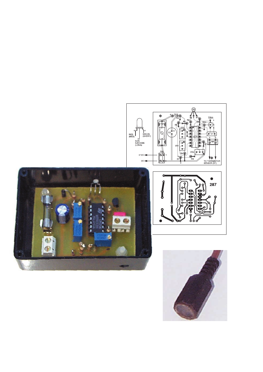
Everyday Practical Electronics, February 2001
95
very small and will not cause any problems.
Note, however, that the l.e.d. will go off if
this were to happen. Should the wire break,
the l.e.d. would show red.
PROTECTION RACKET
The thermistor (R1) now needs to be
waterproofed and protected. Use a short
piece of plastic tube to contain it. In the
prototype unit, the end of an old phono
plug was used.
Push the ends of the connecting wires
through the hole in one end of the tube and
solder them to the thermistor using mini-
mum heat to prevent damage. Do not cut
down the leads (or if you have to, remove the
minimum amount) since even more heat
would reach the thermistor during soldering
and there would be a greater risk of damage.
Push the thermistor and soldered connec-
tions so they are completely inside the tube.
Making certain the soldered joints are kept
well separated, fill the
tube with clear silicone
sealant. This must be
of a type which cures
to become tough and
rubbery. Use the
material available in a
small tube from vari-
ous manufacturers
(such as Loctite Clear
Adhesive Sealant).
Products such as
“bathroom sealant’’
have not been tested
and might not be
suitable.
Check that all bare wires and the ther-
mistor itself are deeply embedded in the
silicone material and allow it to harden. It
is absolutely essential for the thermistor
and its end leads to be completely water-
proofed and great care must be taken over
this process. The operating points will be
greatly affected by even small traces of
moisture. The completed sensor appears in
the photograph.
Leave the sensor for 24 hours (or what-
ever curing time is shown on the tube) for
the material to harden. It must now be
handled with care. Take care not to put the
connecting lead under any strain.
CASING UP
The p.c.b. should now be attached
inside a small plastic case. Where the unit
is being used in a car, the box need only be
large enough to accommodate the circuit
panel plus a little extra to allow for con-
nections to be made to the p.c.b.-mounted
terminal blocks.
If an internal 9V battery is used, you
will need a larger box. You also need to
include a push-to-make switch (S1) in the
positive supply lead to conserve battery
life.
Measure the position of the l.e.d. on the
p.c.b. and drill a hole in the front of the
box to correspond with it. This should
only be large enough to allow the tip of
the l.e.d. to pass through.
STIRRING IT
With the aid of an assistant, keep the oil
stirred constantly and take a continuous
note of its temperature.
When the temperature rises to 2°C,
adjust preset VR2 anti-clockwise to the
point where the green l.e.d. just comes on
(the display will now show yellow). When
the temperature reaches 4°C, adjust VR1
anti-clockwise so the red l.e.d. just goes
off (the colour is now green). When 6°C is
reached, adjust VR3 clockwise until the
l.e.d. goes off (no colour shows).
You may need to repeat the procedure
several times to obtain the required operat-
ing points.
BE PREPARED
The following assumes that the Ice Alert
circuit is to be used in a vehicle. If not,
work accordingly.
Decide on a suitable position for the
main unit. The l.e.d. should be clearly vis-
ible from the driving position. Attach it
using a “Velcro’’ pad.
Decide on a suitable site for the sensor.
This needs to be placed as low as possible
or the temperature indicated may not be a
true reflection of that near the road. Also,
it must be kept as far away as possible
from the exhaust system or anything else
which becomes hot.
There will probably be a suitable site in
the region of the front bumper. Try to find
a place where there will be a free flow of
air around the sensor unit while the car is
moving.
Measure the length of light-duty two-core
wire needed to connect the thermistor sensor
to the main unit. This does not need to be of
automotive quality but it must be of the
stranded type. Do not use single-core wire
or it would break easily in service.
“Ordinary’’ (non-automotive) wire may
be used because, in the event of a short-cir-
cuit between the “live’’ sensor wire and the
car chassis (0V) or between the wires, the
maximum current which can flow is limited
by resistors R2 and R4 in series. This will be
Ice Alert completed circuit board secured inside a small plastic box with nylon
fixings. The tri-colour l.e.d. can be seen at the top.
Fig.3. Printed circuit board component
layout and full size foil master pattern.
The bead thermistor temperature sen-
sor encased in a phono plug.

Hold the p.c.b. in position just above the
base of the box and gently bend the l.e.d.
leads as necessary so its tip takes up the cor-
rect position in the hole drilled for it. Mark the
positions of the p.c.b. fixing holes. Remove
the p.c.b. again and drill these through.
Make a hole for on-off switch, S1 (if
used). Drill a small hole in the side near
terminal block TB2 position for the power
supply wires (unless an internal supply is
used) and a further one near TB1 for the
sensor wires.
Attach the p.c.b. using small nylon fixings.
Place plastic washers on the bolt shanks to
keep the soldered joints on the underside
clear of the base of the box. Make sure the
l.e.d. leads are not left under any strain.
INSTALLING
Attach the thermistor sensor in its chosen
position. This can possibly be done using a
small plastic clip or some epoxy resin adhe-
sive. It is important to support the connecting
wire close to the sensor using a further clip.
This will remove the strain at the point where
it enters the tubular “casing’’.
Route the sensor wire back to the main
unit. Note: whenever it passes through a
hole in metal, a protective rubber grommet
must be used. Pass the wires through the
appropriate hole in the box and connect
them to TB1.
CONNECTING UP
Connections now need to be made to the
car electrical system. Before proceeding,
the car battery must be disconnected.
(Check the car’s manual to make sure it is
OK to disconnect the battery before pro-
ceeding.) This is essential procedure. If
you do not do it, there is risk of causing a
short circuit which could result in wires
becoming red hot and burns to the skin.
The supply must be made using light-duty
auto-type cable and with proper car-type
connectors.
If you have a radio of the type having a
numerical code, make sure you have this
available to re-enter it when the supply is
re-established. Also make sure you know
how to do this by referring to the instruc-
tions supplied with the radio.
A safer alternative to making direct con-
nections would be to plug the unit into the
cigar lighter socket. This method is rather
less attractive but does have the advantage
of being quick and easy.
WIRING UP
For permanent wiring, connect TB2/1 to
a point via an existing fuse which is live
only when the ignition is switched on and
TB2/2 to an existing earth point (car chas-
sis). It may be that the easiest place to
obtain a feed to the circuit is at the rear of
the radio or audio system. Connections to
existing wires may be made using “snap-
lock’’connectors.
If you decide to use the wires leading to
the radio, identify the correct positive one
to use because there are likely to be two of
them. One is a constant +12V feed to
maintain the memory settings and the other
will probably be via the “car radio’’ posi-
tion on the ignition switch. The latter
would be suitable for the new circuit.
If any wire passes through a hole in
metal, a rubber grommet must be used to
prevent cutting by the sharp edge and pos-
sibly causing a short-circuit. Apply strain
relief to both the sensor and power supply
wires inside the case by applying tight
cable ties to them.
Re-connect the car battery and switch on
the ignition. The l.e.d. should be off
(assuming the temperature outside is above
the upper fixed point). You could wait for a
cold day to make a final test. However, a
rough check on operation could be made
by using a freezer spray applied to the sen-
sor. Remember, it will take some time to
respond.
When using the Ice Alert for other than
car purposes, it may be necessary to
place the sensor more than 10m from the
main unit. This could be necessary, for
example, if you wished to monitor the
temperature in a remote greenhouse from
a point inside the house. In cases such as
these, check that the l.e.d. sections oper-
ate relatively “cleanly’’ (without too
much flickering).
This type of problem
could probably be
reduced by using light-
duty single screened
cable for the inter-con-
necting lead instead of
ordinary twin wire. The
screening would be con-
nected to 0V (that is to
TB1/2) and the inner
core to TB1/1. Note that
the resistance of any
wiring used will be much
less than that of the thermistor. The effect
of the resistance of the connecting lead is
therefore negligible.
CHOICE OF
THERMISTOR
The circuit will work correctly if the
specified thermistor is used. However, it is
appreciated that some readers will be
restricted in their choice of thermistor.
If you must use one of a different pat-
tern, use the usual “negative temperature
coefficient’’ variety (that is, as the temper-
ature rises, the resistance falls) having a
resistance of some hundreds of kilohms at
0°C. Halve this figure and select the near-
est available value of fixed resistor. Use
this in the R2 position.
If the circuit now works correctly, all well
and good. If not, use link wires instead of
resistors R3, R5, R6 and R7. This will give
the maximum range of adjustment of the
preset potentiometers (from 0V to 5·1V).
Although they may be more awkward to
adjust, it should now be possible to set up
the correct operating points.
RESPONSE TIME
Although it takes a while for the sensor
to respond to large changes in temperature,
this is not generally a problem. While the
car is parked, the sensor will assume the
temperature of the surrounding air.
When driving along, the changes will
probably not be very great and the sensor
should respond within a few minutes. If the
sensor is placed in the air flow, the
response will be faster.
When used in a vehicle, the Ice Alert
MUST NOT be relied on by the driver or
used as a substitute for normal driving vig-
ilance. It is designed simply to provide
additional information which may assist
safe driving.
$
96
Everyday Practical Electronics, February 2001
E
EP
PE
E B
BIIN
ND
DE
ER
RS
S
KEEP YOUR MAGAZINES SAFE – RING US NOW!
This ring binder uses a special system to allow the issues to be easily removed and re-inserted without any
damage. A nylon strip slips over each issue and this passes over the four rings in the binder, thus holding the
magazine in place.
The binders are finished in hard-wearing royal blue p.v.c. with the magazine logo in gold on the spine. They
will keep your issues neat and tidy but allow you to remove them for use easily.
The price is £5.95 plus £3.50 post and packing. If you order more than one binder add £1 postage for each
binder after the
initial
£3.50 postage charge (overseas readers the postage is £6.00 each to everywhere except
Australia and Papua New Guinea which costs £10.50 each).
Send your payment in £’s sterling cheque or PO (Overseas readers send £ sterling bank draft, or
cheque drawn on a UK bank or pay by card), to Everyday Practical Electronics, Allen House, East
Borough, Wimborne, Dorset BH21 1PF. Tel: 01202 881749. Fax: 01202 841692.
E-mail: editorial@epemag.wimborne.co.uk.
Web site: http://www.epemag.wimborne.co.uk
We also accept card payments. Mastercard, Visa or Switch (minimum
card order £5). Send your card number and card expiry date plus Switch
Issue No. with your order.
Ice Alert
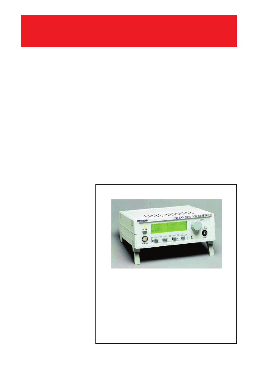
V
IRUS
wars have taken a nasty new twist.
E-mail viruses are getting past anti-
virus software by disguising themselves as
help files which hide in plain text that had
previously been thought safe. Anti-virus
software must work in completely new
ways to trap them. There is widespread
confusion over what systems are at risk
and how best to protect them.
VIRUS EXECUTIVES
Until recently viruses spread as exe-
cutable code programs, attached to plain
text E-mails. The text message encourages
the recipient to open the attachment by
clicking on it. This runs the program
which deliberately corrupts data on the
PC’s hard disk, makes copies of itself and
attaches them to outgoing E-mails, so as to
spread the infection. Traditional anti-virus
software scans attachments before they are
opened, looking for the “signature” of
known viruses. PC users have felt safe to
open and read E-mails as long as they do
not click on any attached file.
Bubble Boy, the first virus to infect with-
out an attachment, exploited a security
loophole in Microsoft’s Outlook Internet
mail reader. The virus code is written as
lines of HTML code which are included in
the text message. Outlook treats the text as
an Internet page and runs the code to
release the virus. Expert PC users who
understand the risk, and also understand
Microsoft’s jargon, can download a pro-
gram which modifies Outlook to stop it
being fooled (http://www.microsoft.com/
technet/security/bulletin/ms00-046.asp).
BEWARE SILLY TITLES
Now a new virus, confusingly known as
Verona, Romeo and Juliet or BleBla plays
a much more devious trick which is likely
to fool a wider range of Internet mail read-
ers. A text message with a silly title, such
as Hey You, Sorry or From Shake-Beer,
arrives with two attached files, a Help file
called Myjuliet.chm and a program called
MyRomeo.exe. Just reading the text mes-
sage makes Windows save the two attach-
ments to its standard Temporary folder
where the Help file automatically runs and
triggers the program to infect the PC. This
then tries to send copies to other addresses
stored in the mail reader.
Romeo and Juliet does no damage to the
hard disk and has not spread because the
Polish Internet servers it uses to spread
infection were quickly shut down. So there
has been very little publicity.
“But the code now exists as a template
which the hacker community can share
and modify to make it much more
dangerous” warns Nick Galea, CEO of
GFI, a Maltese company which makes
software to protect office networks. “Then
we shall see PCs damaged as soon as
people read a text message.”
Galea thinks that protection software
must start checking E-mails for the effects
viruses may cause, not just known
signatures.
SYMANTEC’S WARNING
Eric Chien,
chief researcher at
Symantec’s Anti-Virus Centre, warns that
this is much easier with office networks
than standalone PCs. A network server can
store and check all incoming E-mails
before distributing them to office staff.
Individual PCs collect E-mail direct from
the Internet. Symantec has developed a
system called PopProxy which shunts
incoming E-mail into a buffer file on the
PC, and checks plain text for tell-tale code.
The user only sees the mail after it has
been checked. Symantec has built
PopProxy into the latest version of its
Norton Anti-Virus software, NAV 2001,
but done surprisingly little to explain or
promote it.
Graham Cluley of Sophos thinks the
only long term solution is to use propri-
etary E-mail services and readers, such as
Compuserve, AOL or Cix, which treat text
only as text, ignore any lines of code
which are embedded and never dress plain
text up as HTML.
“Better to choose a safe reader in the
first place, than go on spending money on
anti-virus software that tries to make
unsafe readers safe”. Opinions differ on
what Internet readers are safe, but the one
thing everyone agrees on is that Microsoft,
the most widely used, has been the least
safe. All too often it sends the text twice in
the same message, once plain and safe and
once in HTML and risky. The sender is not
usually aware of this.
N
Ne
ew
ws
s .. .. ..
A roundup of the latest Everyday
News from the world of
electronics
T
TE
EX
XT
T F
FIIL
LE
ES
S N
NO
OT
T IIM
MM
MU
UN
NE
E T
TO
O V
VIIR
RU
US
SE
ES
S
Contrary to what is widely believed, the latest computer viruses
can
live and
propagate through text files. Barry Fox alerts us.
98
Everyday Practical Electronics, February 2001
2
20
0M
MH
Hz
z F
FU
UN
NC
CT
TIIO
ON
N G
GE
EN
NE
ER
RA
AT
TO
OR
R
VANN Draper Electronics, the manufacturer and world-wide distribution company
for Grundig
digimess
Instruments, has announced a new 20MHz function
generator.
The FG100 provides a wide frequency range of 0·5Hz to 20MHz with a high
accuracy of 0·5 per cent monitored by an internal microprocessor. Output wave
shapes include sine, triangle, square and sawtooth, with variable symmetry
enabling pulse signals to be produced.
A back-lit alphanumeric display provides concise readings of settings and fre-
quency, as well as communication modes when using the built-in RS232C
interface.
Other key features include internal sweep, d.c. offset, variable output level from
10mV to 10V, plus sync output. It operates as stand-alone or PC controlled.
Priced at £199 the FG100 is available direct from Vann Draper or their authorised
distributors. For more details contact Vann Draper Electronics Ltd, Dept EPE,
Stenson House, Stenson, Derby DE73 1HL. Tel: 01283 704706. Fax: 01283
704707. E-mail: sales@vanndraper.co.uk. Web: www.vanndraper.co.uk.

THE cellphone companies are spending
billions on licences to spend more billions
building third generation networks. The
last thing they need is competition from
conventional radio services which can
offer 3G features at far lower cost.
After ten months of trials a Californian
startup, backed by Texas Instruments,
Motorola and Paul Allen, is offering digi-
tal radio broadcasters a system which
competes head-on with 3G. Command
Audio lets drivers listen to the latest traf-
fic, weather, sports and news information,
the moment they get in the car. While dri-
ving they can switch between music in real
time, and the latest news updates.
The technology was developed and
patented by Command Audio in
Redwood City and John Ryan, who
heads up Macrovision, the world leader
in video copy protection. A control cen-
tre compresses a wide selection of con-
ventional radio programmes into
2·4Kbps streams and broadcasts them as
data channels. The receiver, which looks
like a chubby TV remote control, has
memory chips which continually store
the last eight hours of sub-channel audio,
for instant skip and scan access at the
press of a button.
Command has trialled the system in
Denver and Phoenix using data subcarriers
on FM radio stations and prototype hand-
sets made by RCA and Thomson. Most
countries, except the US, are adopting the
European digital radio system which can
carry much more digital data than FM
radio – around 1·5Mbps of which some 75
per cent is used for music and the rest set
aside for data (the UK allocation is 20 per
cent or 230Kbps but could be increased;
Singapore already allows 35 per cent). So
far digital broadcasters have used their
data capacity to deliver Internet pages but
Command believes drivers would prefer
on-demand audio.
Quentin Howard, Chief Executive of
the UK’s commercial digital radio net-
work Digital One, has long enthused
over data by radio. He says: “We have
built a radio network that can deliver
very high data rates to an unlimited
number of users from just 70 transmit-
ters. The new cellular networks will each
require some 6000 transmitters and will
never be able simultaneously to serve
the same number of consumers as we
can”.
Howard thinks Command Audio is a
“neat idea” but questions whether listeners
will be prepared to pay the $12 a month
subscription which Command is talking
about.
MAPLIN CD-ROM
MAPLIN Electronics’ latest CD-ROM
catalogue has recently been released. It
contains around 15,000 products, ranging
from individual components to state-of
the-art electronic equipment.
The CD-ROM, which has been devel-
oped in HTML, is designed with the same
functions as Maplin’s website and runs on
Internet Explorer 5 (available to download
from the CD-ROM).
The new “Web-enabled” CD-ROM
allows you to construct your order offline.
Once Submit has been pressed the brows-
er is launched automatically allowing
orders to be stock checked and processed
for sameday despatch.
To receive a copy of the CD-ROM,
which costs £1.99, contact the Order Line
on 0870 264 6000 and quote order code
CQ07,
or click on the icon at
www.maplin.co.uk. Maplin’s press
release states the contact address as
Maplin Electronics,
Valley Road,
Wombwell, Barnsley S73 0BS. Mention
EPE when contacting Maplin.
RIPPING MUSIC
By Barry Fox
MP3 ripping is now a living room reality.
Korean electronics giant Samsung is the
first big brand name in household audio to
offer a range of mini, midi and micro hi-fi
systems with integrated MP3 ripper. Until
now consumers have had to use a PC to
download MP3 music from the Internet or
“rip” CDs by converting the content into
MP3 (MPEG-1, Layer 3) code. The PC
must then be connected to a portable solid
state player like the Diamond Rio, to
transfer the music for portable playback.
Three new home audio stacks from
Samsung (costing between £350 and £500)
have a CD player, built-in MP3 encoder and
dockable Yepp solid-state player with 32MB
SmartMedia card for 30 minutes recording
time. The owner just plays a disc while trans-
ferring the music to the portable, without
needing to own a PC or know anything about
computers and computing.
ROBOT KITS
AN E-mailed newsletter from Quasar
Electronics informs us that “We have
introduced a range of educational elec-
tronic robot kits. We really like them. They
are high quality, excellent designs, good
fun and educational. What more could you
ask for in life . . .’’. Indeed!
Quasar have lots more educational kits
(and others). You will find info about them
at: www.quasarelectronics.com/educa-
tional-electronic-projects.htm. There is
also a mirror site at www.electronic-kits-
and-projects.com/home.htm.
Tel: 01279 306504.
E-mail: sales@quasarelectronics.com.
Note Quasar’s fax: 07092 203496.
SQUIRES TOOLS
SQUIRES Model and Craft Tools 2001 cat-
alogue has recently arrived at HQ. It contains
an excellent (dare we say “fully comprehen-
sive”?) variety of the tools and associated
modelling accessories that any self-respect-
ing hobbyist requires. The electronic compo-
nents range has been expanded and all goods
are available by post-free mail order.
In over 400 well presented and itemised
pages, Squires’ cat is a must to have on your
workbench. It’s also free of charge – just
contact Squires and they’ll send you a copy:
Squires Model and Craft Tools, Dept
EPE, 100 London Road, Bognor Regis, W.
Sussex PO21 1DD. Tel: 01243 842424.
Fax: 01243 842525. (No Web as yet, but
it’s on its way!)
EOCS Website Launched
THE
Electronic Organ Constructors
Society website www.eocs.org.uk is now
on-line. So far as is known, the EOCS is
the only international society devoted to
amateur electronic organ building. If this
is your interest, have a good browse of the
site, and even participate in the EOCS
equivalent of our Chat Zone.
You can also contact the Society via
Trevor Hawkins, Hon. Sec., EOCS, 23
Blenheim Road, St Albans, Herts AL1
4NS. Tel: 01727 857344. Mention EPE.
Everyday Practical Electronics, February 2001
99
B
B..A
A..E
E..C
C.. S
SE
EE
EK
KS
S P
PIIC
C E
EN
NT
TH
HU
US
SIIA
AS
ST
TS
S!!
THE Editorial of the British Amateur Electronics Club’s recent newsletter
laments the decline in contributions to it. The Editor, George Burton, expressed
the opinion that the B.A.E.C. should follow
EPE’s example and place a strong
emphasis on the use of PIC microcontrollers.
George asks, “How many of our members have seen a PIC chip let alone
used one? It is these members I am trying to find. We have to start using these
multi-purpose components or shall fade away – reminiscing how we used to do
it”.
We suggest that any reader who knows about PICs (and there are many
thousands of you) and would like to join the B.A.E.C. and share their
knowledge with other members through contributions to the Newsletter should
do so
now. You will be warmly welcomed, as will other non-PIC electronics
enthusiasts.
The Club is open to anyone interested in electronics – and that’s all of you!
(We know that a
trickle of you have joined recently, well done. How about a
flood – dare we mention the word in the present climate?)
The B.A.E.C. has existed for many decades and deserves your support so
that it can progress into the future. We encourage you to contact the Chairman,
George Burton, 581 Fishponds Road, Fishponds, Bristol BS16 3AA. Tel: 0117
9654800. E-mail: prontaprint.bristol@cableinet.co.uk. Web: http://members.tri-
pod.com/~baec. Mention
TRAFFIC REPORTS COMPETITORS
By Barry Fox
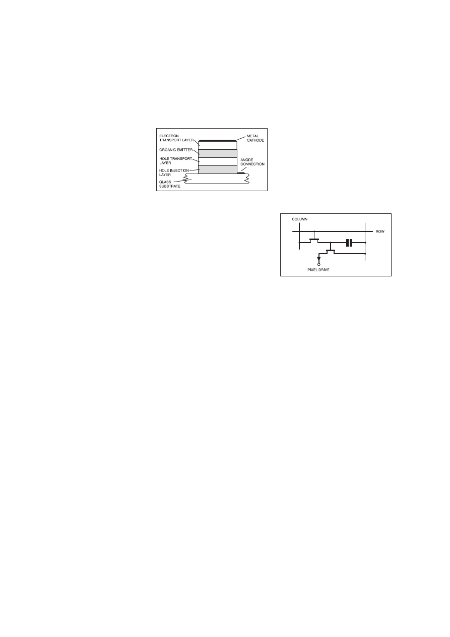
S
URPRISINGLY the cathode ray tube
still offers the best performance for
many display applications. Modern alter-
natives, including liquid crystal displays,
electro-luminescent displays and a variety
of other types, have not managed to cap-
ture the market to the degree achieved by
the c.r.t.
Organic Displays
However, a new breed of displays is
beginning to appear. Termed Organic Light
Emitting Diode (OLED) displays, they
offer some real advantages over displays
that are currently available. Unlike tradi-
tional liquid crystal displays (l.c.d.s) these
OLED displays are self-luminous and do
not require back-lighting. As back-lights
take up additional space it means that
OLED displays can be made thinner and
more compact than many other types.
A further advantage is that OLED dis-
plays have a very wide viewing angle. This
can be up to 160 degrees, even in bright
sunlight.
They also consume relatively little
power, and can run from supplies between
2 and 10 volts. This makes them very
attractive for many applications where
voltage supplies and power consumption
are an issue.
A further advantage of the low power
consumption is an improvement in EMC
performance. As drive levels are low, the
risk of radiating signals is much reduced,
and this is particularly useful when design-
ing products for which regulations on
emissions are relatively tight.
Operation
There are two basic types of display,
active and passive. However, they both rely
on the same basic principles. The basic
OLED cell structure consists of four layers
of organic material positioned between a
metallic cathode and a transparent anode.
The organic layers comprise a hole injec-
tion layer, a hole transport layer, an emis-
sive layer and an electron transport layer,
as shown in Fig.1.
A voltage is applied across the cell and
positive and negative charges recombine in
the emissive layer as in an ordinary diode. As
a result of the recombination light is pro-
duced. Most of the recombination takes place
in the emissive layer, although some does
occur elsewhere. To improve the efficiency
the design of the structure is optimised to
ensure this recombination takes place in the
emissive layer where light is produced.
Further enhancement of the light output is
gained by doping the emissive layer with a
small level of highly fluorescent molecules.
Passive displays
Passive OLED displays are less compli-
cated than their active counterparts. They
are well suited for low cost and low infor-
mation content applications like alphanu-
meric displays. They are formed by
providing an array of OLED pixels. The
cathodes and anodes are arranged in rows
and columns and by selecting the relevant
row and column the required pixel can be
activated. These can be scanned and suc-
cessively lit to give the required pattern.
Kodak have developed a unique method
for fabricating these devices. The simplici-
ty of the process means that costs are kept
to a minimum.
First a “rib” or “base and pillar” structure
is pre-formed on patterned anode lines.
The organic materials are then deposited
and the nature of the deposition process
means that the OLED display panel with
the required electrical isolation for the
cathode lines is automatically formed.
One of the major advantages of this
method of fabrication is that no new
processes have been introduced and it can
be easily be adapted to high throughput
manufacturing.
Active displays
As the name suggests, the passive display
does not include any additional electronics.
This limits its application to the more simple
displays where the individual rows and
columns can be easily accessed. Once the
pixel count rises to the level that graphics can
be displayed it becomes necessary to include
the drive circuitry within the display itself.
This is normally included in the substrate
where a back plane can be constructed. In
this way a very sophisticated high resolution
graphics display can be created, suitable for
applications like television screens, comput-
er monitors and the like.
The use of polysilicon technology is key
to the manufacture of these displays
because it provides a high carrier mobility.
This gives the thin film transistors (TFT)
that are used a high current carrying capac-
ity and fast switching speed essential for
the correct operation of these displays.
100
Everyday Practical Electronics, February 2001
New Technology
Update
Last month Ian Poole discussed organic
lasers. He now looks at the emerging
technology of organic l.e.d.s.
Each individual pixel in the display can
be addressed separately via the electronic
circuitry in the back plane that consists of
the TFTs and associated capacitors.
The basic circuitry is relatively simple
and combined with the straightforward
fabrication of the display itself, there are
no intrinsic limitations to the pixel count,
resolution or actual size of the display.
This makes it particularly attractive for
high resolution displays of the types need-
ed for televisions and computer monitors.
Missing pixels
Missing pixels occur on any large dis-
play. It is normal to allow displays to be
sold that have a small number of defects. If
this were not done then the yields would be
unacceptably low and prices exceedingly
high. When this occurs with an OLED dis-
play the pixel is left dark, and this is
unlikely to be noticed by the eye. Faulty
l.c.d. displays often produce a point of
light and this is far more visible.
Future
Whilst much of the work that has been
described has been undertaken by Kodak,
other companies are also working on the
displays and forming alliances that will
enable production to move forward more
swiftly.
In one development, DuPont Displays
have acquired Uniax Corporation of
California. Other companies are active as
well. In an alliance, Covion Organic
Semiconductors GmbH from Frankfurt
have linked up with eMagin Corp in New
York. In this alliance Covion will provide
the display technology for use in eMagin’s
current and future display products. This
alliance is in turn partnering IBM to fur-
ther develop OLED-on-silicon technology
for use in a number of advanced display
based applications.
In view of the level of work being under-
taken, it can be seen that the industry is
taking this new development very serious-
ly, and soon OLED displays should start to
appear in products on the market in large
quantities.
Fig.1. OLED Structure
Fig.2. Active display driver circuit
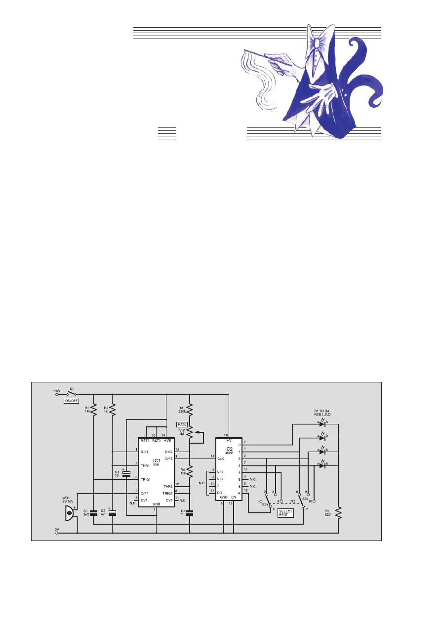
TToopp TTeennnneerrss
A
S WELL
as its obvious benefit to
musicians (aspiring or arrived), this
project can be used as a pacer by
those busy with aerobics or other on-the-
spot exercises. Its display consists of a row
of light-emitting diodes (l.e.d.s). These are
flashed one at a time, in order from left to
right and repeating continuously.
A rotary switch selects the number of
l.e.d.s flashed, which is equal to the num-
ber of beats in a bar. It allows the user to
choose between 2/4, 3/4 and 4/4 time
signatures:
1, 2, 1, 2, 1, 2, ...
1, 2, 3, 1, 2, 3, 1, 2, 3, ...
1, 2, 3, 4, 1, 2, 3, 4, 1, 2, 3, 4,...
Another common time signature is 6/8
but, as the fourth note in each bar is often
slightly accented, this can be obtained by
using the 3/4 setting and doubling the
tempo. The Tempo (Rate) is set by a vari-
able resistor (potentiometer) and covers the
range from Largo to Presto.
The Simple Metronome also has an
audio output. This is provided by a piezo-
electric sounder which emits a short beep
at the beginning of each bar, that is, on the
count of “one’’, which is when the left-
most l.e.d. comes on.
HOW IT WORKS
The full circuit diagram for the Simple
Metronome is shown in Fig.1. The basic
tempo is provided by timer IC1. This i.c. is
a dual version of the well-known 555 timer.
The other timer within IC1 is used to
switch on the piezoelectric sounder WD1
when triggered.
The timer that controls tempo is wired as
an astable multivibrator, which means that
it generates a continuous series of pulses at
a definite rate. Its frequency is controlled
by the setting of Rate control VR1.
With the values shown in Fig.1, the fre-
quency of the astable is variable from just
over 1Hz up to 6Hz. A polyester capacitor
is used for C4 because the capacitance of
this type does not vary with age and with
use, as does that of the electrolytic type.
The output signal at pin 9 from the
astable goes to the clock input (pin 14) of a
divide-by-eight counter, IC2. The counter
is incremented on the rising edge of each
pulse. It has eight outputs, of which one
goes to logic high at each count. The others
remain at logic low.
For the counter to run, its reset input (pin
15) must be held low. A brief high level on
the reset input triggers the counter to reset
to zero.
As counting proceeds, the outputs would
normally go high in order from 0 to 7,
repeating. However, we use only the first
five outputs in this circuit. For example, if
we set Beat switch S2a for four beats to the
bar, IC2 outputs 0, 1, 2 and 3 go high in
that order. Then, when output 4 goes high,
the high level is fed through S2 to the reset
pin (IC2 pin 15).
Thus, as soon as output 4 (which would
be a count of 5) goes high, the counter is
SIMPLE
METRONOME
This short collection of projects, some useful, some instructive and some amusing, can be
made for around the ten pounds mark. The estimated cost does not include an enclosure.
All of the projects are built on stripboard, and most have been designed to fit on to boards of
standard dimensions. All of the projects are battery-powered, so are safe to build. In a few
cases in which, by its nature, the project is to be run for long periods, power may be provided
by an inexpensive mains adaptor. Again, the cost of such a unit is not included.
102
Everyday Practical Electronics, February 2001
OWEN BISHOP
Project 6
Ω
µ
µ
µ
Fig.1. Complete circuit diagram for the Simple Metronome.
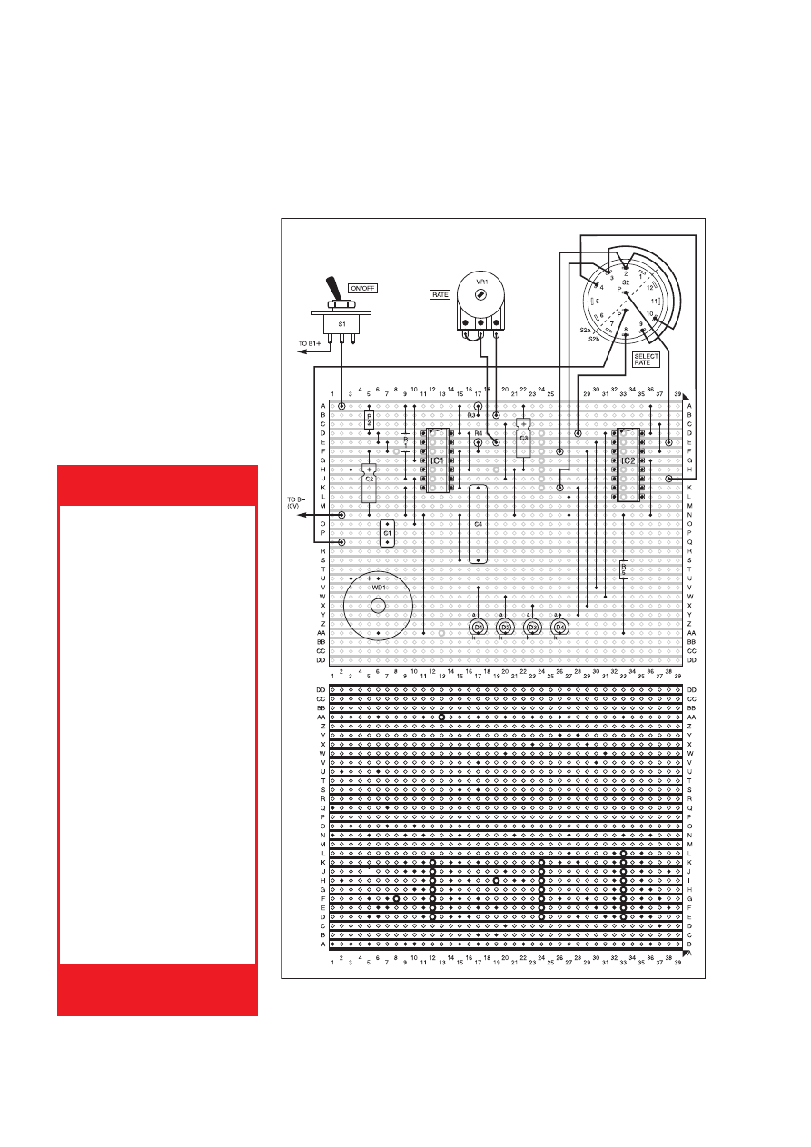
reset to zero. This takes only a few mil-
liseconds, so it appears that the counter
goes straight from count 4 to count 0.
Similarly, we can use S2a to select outputs
3 and 2 to make the counter reset on the
counts of 4 and 3 for 3/4 and 2/4 times.
AUDIO COUNT
The audio bleep, count one, is produced
by piezoelectric sounder WD1 that normal-
ly produces a high-pitched tone when it is
switched on. To make the short “bleep’’, we
use the second timer within IC1, wired as a
monostable multivibrator.
With the values chosen for resistor R2
and capacitor C2, the monostable delivers a
single high pulse of 0·05s duration every
time its trigger input (pin 6) is made low.
Note that we need a low-going input to trig-
ger the timer (compare this to resetting,
which requires a high input).
To make the “bleeps’’ coincide with the
first count of each sequence, we need to
trigger the timer as the l.e.d. goes out in the
final count of each sequence. If there are
four beats to the bar, for example, the
monostable is triggered when the count of
three ends.
The required connections are made by
switch S2b. The pole (p) or wiper of S2b is
connected through a capacitor (C1) to the
trigger pin (pin 6) of IC1. This input is nor-
mally held high by the pull-up resistor R1.
A low-going level at the pole of S2b is
sufficient to pull the input voltage down
below 2V for long enough to trigger the
monostable.
When IC2 switches the l.e.d.s on or off,
this alters the load on the supply and may
cause voltage spikes that upset the action of
the counter. To avoid these, capacitor C3 is
connected across the supply rails.
CONSTRUCTION
The Simple Metronome circuit is built
on a 0·1 inch matrix rectangle of strip-
board, having 29 copper strips by 39 holes.
The component layout, interwiring and
details of breaks required in the copper
tracks are shown in Fig.2.
The unit runs on 6V, which may be pro-
vided by four 1·5V dry cells in a battery box.
Alternatively, use a 6V mains power supply
adaptor. An inexpensive one supplying
100mA at 6V d.c. unregulated is adequate.
If you are intending to house this project
in a case, there are three items that should
be mounted on the case: the power On/Off
switch S1, the variable potentiometer VR1,
and the rotary selector switch S2.
Everyday Practical Electronics, February 2001
103
Resistors
R1
1M
R2
1k
R3
220k
R4
10k
R5
820
W
All 0·25W 5% carbon film or better.
Potentiometer
VR1
1M rotary carbon, linear
Capacitors
C1
2n2 polyester film
C2
47
m elec. 16V, axial
C3
10
m elect. 16V, axial
C4
1
m polyester
Semiconductors
D1 to D4
5mm red l.e.d. (other
sizes or colours
optional)
IC1
556 dual timer
IC2
4022 CMOS divide-by-
8 counter, with 1-of-8
outputs
Miscellaneous
S1
s.p.s.t. toggle switch
S2
2-pole 6-way rotary
switch (see text)
WD1
single-tone piezoelectric
sounder, 3V to 16V.
Stripboard 0·1 inch matrix, size 29
copper strips by 39 holes; 14-pin i.c.
socket; 16-pin i.c. socket; battery holder,
with 4 × 1·5V cells or unregulated mains
adaptor, see text; 1mm solder terminal
pins (10 off); pointer knobs for VR1 and
S2; multistrand connecting wire; solder,
etc.
COMPONENTS
Approx. Cost
Guidance Only
£
£1
10
0
excluding case
See
S
SH
HO
OP
P
T
TA
AL
LK
K
p
pa
ag
ge
e
Fig.2. Simple Metronome stripboard component layout, interwiring to off-board
components and details of breaks required in the copper tracks.

The rotary switch is relatively expensive
and may put the cost of the project just
above the £10 limit if you cannot find a
cheap one. The component wiring diagram
of Fig.2 shows a 2-pole 6-way switch, but a
3-pole 4-way switch or a 4-pole 3-way
switch can be used equally well.
Alternatively, instead of a switch, you
can solder a “flying lead” to each of the
solder pins at points Q2 and E38 in Fig. 2.
Terminate each of the flying leads with a
miniature crocodile clip. These clips are
used for connecting to two of the terminal
pins at D28, F26, K26 and J38, depending
on the “beat’’ setting required.
FINAL ASSEMBLY
AND CHECKING
Following the component layout in
Fig.2, first assemble the two circuits con-
nected to IC1. When it is complete, tem-
porarily connect the solder terminal pin at
Q2 to the positive supply. If you then trans-
fer the connection briefly to the 0V line, a
short “bleep’’ should be heard.
Use a voltmeter or logic probe to moni-
tor the output from the astable circuit at pin
9. Check that the frequency of the signal
varies according to the setting of Beat
control VR1.
Now complete construction of the pro-
ject by adding the components associated
with IC2 and the l.e.d.s. Wiring for the 2-
pole 6-way Beat select rotary switch (S2)
is also shown in Fig.2. Try to mount the
l.e.d.s in as straight a row as possible and
at the same height above the board. Check
that the circuit now works as described
earlier.
Finally, mount the off-board components
(if the project is cased) and add labels for
S2 and VR1. The latter may be calibrated in
frequency or in musical terms.
$
Component layout on the prototype circuit board. The finished unit can be mounted
in a plastic box, with holes drilled for the l.e.d.s.
104
Everyday Practical Electronics, February 2001
How To Use Graphics L.C.D.s with PICs (Supplement)
The main point of consideration encountered when checking out
components for the Graphics L.C.D. Demo Board, given in this
month’s special supplement, will be the graphics l.c.d. module. The
author used a Powertip PG12864 graphics display purchased from
RS Components, and is currently priced at £27.92 (excl VAT/p&p).
This can be ordered through Electromail (
2 01536 304555 or
http://rswww.com), code 329-0329.
We understand that Magenta (
2 01283 565435 or www.magen-
ta2000.co.uk) are hoping to supply graphic displays, with pin a con-
nector at a reasonable cost in the near future. We suggest readers
track their web site or give them a call for the latest news.
Contrary to the components list, you need an
unprogrammed
PIC16F877 chip; three lots of software will be installed and manipu-
lated as you progress. A scan through our advertising pages should
produce suppliers of PICs. Also, it follows that you must have a PIC
programmer (such as the
PIC Toolkit Mk2 – May/June ’99) to accom-
pany this design.
The printed circuit board is available from the
EPE PCB Service,
code 288. The software is available on a 3·5in. PC-compatible disk
(
EPE Disk 4) from the EPE Editorial Office for the sum of £3 each
(UK), to cover admin. costs. (For overseas charges see page 149). It
is also available free via the
EPE web site:
ftp://ftp.epemag.wimborne.co.uk/pubs/PICS/graphicslcd.
Using The LM3914-6 L.E.D. Bargraph Drivers
Being popular devices, you should have no trouble ordering the
National Semiconductors’ LM3914 (linear), 3915 (log.) and 3916 (VU)
family of l.e.d./bargraph display driver i.c.s, called for in the LM3914-
6 feature, through your local component supplier.
It is a good idea to coat adjoining walls of the l.e.d.s with black paint
to prevent “light spread’’ if making up your own bargraph display. It
was found that 3mm dia. low current l.e.d.s gave the best results,
probably due to less material thickness of the plastic body/shell.
The small, resistor-like, 4·7mH and 1mH r.f. chokes for the Relay
Control unit link cable should be well stocked. The three printed circuit
boards are available from the
EPE PCB Service as a set, codes 289,
290, 291 (see page 149).
Ice Alert
The specified Philips bead thermistor used in the
Ice Alert project
has a rating of 150k
W at 25°C and about 535kW at 0°C. This
device%was purchased from Maplin (
2 0870 264 6000 or
www.maplin.co.uk), code FX43W.
There is some latitude in the range of the thermistor used and it is
appreciated that in some areas constructors will be limited in their
choice. If you must use a different type, select one of the “negative
temperature coefficient’’ variety – that is, as the temperature rises the
resistance falls – having a resistance of hundreds of kilohms at 0°C.
Halve this figure and select the nearest fixed value resistor for R2.
The rest of the components for this unit should be readily available
from our component advertisers. Do not forget, if you are installing the
unit in a vehicle, the supply connections must be made using light-
duty auto-type cable and with proper car-type connectors. Also, make
sure you use nylon fixings when mounting the p.c.b. in its case.
The small printed circuit board is available from the
EPE PCB
Service, code 287 (see page 149). Finally, if installing the unit in a
vehicle, check the car’s manual to make sure it is safe to disconnect
the battery before installation.
PC Audio Power Meter
Several components called for in the
PC Audio Power Meter could
cause local sourcing problems. Most of the items used in the author’s
model came from Maplin (
2 0870 264 6000 or www.maplin.co.uk).
They supplied the 3W and 50W wirewound resistors. To order
write/quote “W’’ then value (i.e. W0·1) for the 3W type and “X’’ then
value (X3R9) for the 50W type. Suitable twin spring-loaded loud-
speaker terminals are also stocked, code BW71P. They do not give an
electrical rating for the terminal.
The Analog Devices AD7896AN 12-bit 8
ms ADC chip and the
ICL7660CPA switched capacitor voltage converter i.c. should be fair-
ly widely stocked. Try Cricklewood (
2 0181 452 0161) and Maplin
(codes NP36P and NR54J respectively). The choice of case is left to
individual taste. But it
must be a metal type, due to heat generated
within the case.
The software for this project is available on a 3·5in. PC-compatible
disk (
EPE Disk 4) from the EPE Editorial Office for the sum of £3 each
(UK), to cover admin costs (for overseas see page 149). It is also
available
free via the EPE web site:
ftp://ftp.epemag.wimborne.co.uk/pubs/audiomet.
Simple Metronome
We do not expect any component buying problems to arise when
shopping for parts for the
Simple Metronome, this month’s Top Tenner
project.
The component wiring diagram shows a 2-pole 6-way rotary switch,
but a 3-pole 4-way or 4-pole 3-way type can also be used in this cir-
cuit. Likewise with the single-tone piezoelectric buzzer, most of these
sounders operate from a broad range of d.c. voltages and many of our
component advertisers will be able to offer a suitable device.
PLEASE TAKE NOTE
Versatile Mic/Audio Preamplifier
May ’00
In a recent issue we highlighted the problems of sourcing the
SSM2166P mic. preamp chip for the
Versatile Mic/Audio
Preamplifier project and asked for help in finding some. We have
just received news that FML Electronics (
2 01677 425840) now
have some in stock.
CROCODILE CLIPS. Small size, 10 each red and
black. Order Ref: 116.
PLASTIC HEADED CABLE CLIPS. Nail in type,
several sizes. Pack of 50. Order Ref: 123.
30A PANEL MOUNTING TOGGLE SWITCH.
Double pole. Order Ref: 166.
SUB MIN TOGGLE SWITCHES. Pack of 3. Order
Ref: 214.
HIGH POWER 3in. SPEAKER (11W 8ohm).
Order Ref: 246.
MEDIUM WAVE PERMEABILITY TUNER. It’s
almost a complete radio with circuit. Order Ref:
247.
HEATING ELEMENT. Mains voltage 100W, brass
encased. Order Ref: 8.
MAINS MOTOR with gearbox giving 1 rev per 24
hours. Order Ref: 89.
ROUND POINTER KNOBS for flatted ¼in. spin-
dles. Pack of 10. Order Ref: 295.
CERAMIC WAVE CHANGE SWITCH. 12-pole, 3-
way with ¼in. spindle. Order Ref: 303.
REVERSING SWITCH. 20A double pole or 40A
single pole. Order Ref: 343.
LUMINOUS PUSH-ON PUSH-OFF SWITCHES.
Pack of 3. Order Ref: 373.
SLIDE SWITCHES. Single pole changeover. Pack
of 10. Order Ref: 1053.
PAXOLIN PANEL. Approximately 12in. x 12in.
Order Ref: 1033.
CLOCKWORK MOTOR. Suitable for up to 6
hours. Order Ref: 1038.
TRANSISTOR DRIVER TRANSFORMER.
Maker’s ref. no. LT44, impedance ratio 20k ohm to
1k ohm, centre tapped, 50p. Order Ref: 1/23R4.
HIGH CURRENT RELAY. 12V D.C. or 24V A.C.,
operates changeover contacts. Order Ref: 1026.
2-CORE CURLY LEAD. 5A, 2m. Order Ref: 846.
3 CHANGEOVER RELAY. 6V A.C., 3V D.C. Order
Ref: 859.
3 CONTACT MICRO SWITCHES, operated with
slightest touch. Pack of 2. Order Ref: 861.
HIVAC NUMICATOR TUBE. Hivac ref XN3. Order
Ref: 865.
2IN. ROUND LOUDSPEAKERS. 50
9 coil. Pack of
2. Order Ref: 908.
5K POT, standard size with DP switch, good
length ¼in. spindle, pack of 2. Order Ref: 11R24.
13A PLUG, fully legal with insulated legs, pack of
3. Order Ref: GR19.
OPTO SWITCH on p.c.b., size 2in. x 1in., pack of
2. Order Ref: GR21.
1000W FIRE SPIRALS. In addition to repairing
fires, these are useful for making high current
resistors. Price 4 for £1. Order Ref: 223.
BRASS ENCASED ELEMENT. Mains working,
80W standard replacement in some fridges but
very useful for other heating purposes. Price £1
each. Order Ref: 8.
PEA LAMPS, only 4mm but 14V at 0·04A, wire
ended, pack of 4. Order Ref: 7RC28.
HIGH AMP THYRISTOR, normal 2 contacts from
top, heavy threaded fixing underneath, think
amperage to be at least 25A, pack of 2. Order Ref:
7FC43.
BRIDGE RECTIFIER, ideal for 12V to 24V charg-
er at 5A, pack of 2. Order Ref: 1070.
TEST PRODS FOR MULTIMETER with 4mm
sockets. Good length very flexible lead. Order Ref:
D86.
LUMINOUS ROCKER SWITCH, approximately
30mm square, pack of 2. Order Ref: D64.
MES LAMP HOLDERS, slide onto ¼in. tag, pack
of 10. Order Ref: 1054.
HALL EFFECT DEVICES, mounted on small
heatsink, pack of 2. Order Ref: 1022.
12V POLARISED RELAY, 2 changeover contacts.
Order Ref: 1032.
PROJECT CASE, 95mm x 66mm x 23mm with
removable lid held by 4 screws, pack of 2. Order
Ref: 876.
LARGE MICRO SWITCHES, 20mm x 6mm x
10mm, changeover contacts, pack of 2. Order Ref:
826.
PIEZO ELECTRIC SOUNDER, also operates effi-
ciently as a microphone. Approximately 30mm
diameter, easily mountable, 2 for £1. Order Ref:
1084.
LIQUID CRYSTAL DISPLAY on p.c.b. with ICs
etc. to drive it to give 2 rows of 8 characters, price
£1. Order Ref: 1085.
THIS MONTH’S SPECIAL
IT IS A DIGITAL
MULTITESTER, com-
plete with backrest to
stand it and hands-
free test prod holder.
This tester measures
d.c. volts up to 1,000
and a.c. volts up to
750; d.c. current up to
10A and resistance
up to 2 megs. Also
tests transistors and
diodes and has an
internal buzzer for continuity tests. Comes complete
with test prods, battery and instructions. Price
£6.99. Order Ref: 7P29.
1mA PANEL METER. Approximately 80mm ×
55mm, front engraved 0-100. Price £1.50 each.
Order Ref: 1/16R2.
VERY THIN DRILLS.
12 assor ted sizes vary
between 0·6mm and 1·6mm. Price £1. Order Ref:
128.
EVEN THINNER DRILLS. 12 that vary between
0·1mm and 0·5mm. Price £1. Order Ref:129.
BT PLUG WITH TWIN SOCKET. Enables you to
plug 2 telephones into the one socket for all normal
BT plugs. Price £1.50. Order Ref: 1.5P50.
D.C. MOTOR WITH GEARBOX. Size 60mm long,
30mm diameter. Very powerful, operates off any
voltage between 6V and 24V D.C. Speed at 6V is
200 rpm, speed controller available. Special price
£3 each. Order Ref: 3P108.
FLASHING BEACON. Ideal for putting on a van, a
tractor or any vehicle that should always be seen.
Uses a Xenon tube and has an amber coloured
dome. Separate fixing base is included so unit can
be put away if desirable. Price £5. Order Ref: 5P267.
MOST USEFUL POWER SUPPLY. Rated at 9V 1A,
this plugs into a 13A socket, is really nicely boxed.
£2. Order Ref: 2P733.
MOTOR SPEED CONTROLLER. These are suitable
for D.C. motors for voltages up to 12V and any
power up to 1/6h.p. They reduce the speed by inter-
mittent full voltage pulses so there should be no
loss of power. In kit form these are £12. Order Ref:
12P34. Or made up and tested, £20. Order Ref:
20P39.
BT TELEPHONE EXTENSION WIRE. This is proper
heavy duty cable for running around the skirting
board when you want to make a permanent exten-
sion. 4 cores properly colour coded, 25m length.
Only £1. Order Ref:1067.
LARGE TYPE MICROSWITCH with 2in. lever,
changeover contacts rated at 15A at 250V, 2 for £1.
Order Ref: 1/2R7.
BALANCE ASSEMBLY KITS. Japanese made,
when assembled ideal for chemical experiments,
complete with tweezers and 6 weights 0·5 to 5
grams. Price £2. Order Ref: 2P44.
CYCLE LAMP BARGAIN. You can have 100 6V 0-
5A MES bulbs for just £2.50 or 1,000 for £20. They
are beautifully made, slightly larger than the stan-
dard 6·3V pilot bulb so they would be ideal for mak-
ing displays for night lights and similar applications.
DOORBELL PSU. This has AC voltage output so is
ideal for operating most doorbells. The unit is totally
enclosed so perfectly safe and it plugs into a 13A
socket. Price only £1. Order Ref: 1/30R1.
INSULATION TESTER WITH MULTIMETER.
Internally generates voltages which enable you to
read insulation directly in megohms. The multi-
meter has four ranges, AC/DC volts, 3 ranges DC
milliamps, 3 ranges resistance and 5 amp range.
These instruments are ex-British Telecom but in
very good condition, tested and guaranteed OK,
probably cost at least £50 each, yours for only £7.50
with leads, carrying case £2 extra. Order Ref: 7.5P4.
REPAIRABLE METERS. We have some of the
above testers but slightly faulty, not working on all
ranges, should be repairable, we supply diagram,
£3. Order Ref: 3P176.
TWO MORE POST OFFICE INSTRUMENTS
Both instruments contain lots of useful parts, includ-
ing sub-min toggle switch sold by many at £1 each.
They are both in extremely nice cases, with battery
compartment and flexible carrying handles, so if you
don’t need the intruments themselves, the case may
be just right for a project you have in mind.
The first is Oscillator 87F. This has an output, con-
tinuous or interrupted, of 1kHz. It is in a plastic box
size 115mm wide, 145mm high and 50mm deep.
Price only £1. Order Ref: 7R1.
The other is Amplifier Ref. No. 109G. This is in a
case size 80mm wide, 130mm high and 35mm deep.
Price £1. Order Ref: 7R2.
HEAVY DUTY POT
Rated at 25W, this is 20 ohm resistance so it could
be just right for speed controlling a d.c. motor or
device or to control the output of a high current
amplifier. Price £1. Order Ref: 1/33L1.
STEPPER MOTOR
Made by Philips as specified for the wind-up torch in
the Oct ’00 Practical Electronics is still available,
price £2. Order Ref: 2P457.
SOLDERING IRON, super mains powered with
long-life ceramic element, heavy duty 40W for the
extra special job, complete with plated wire stand
and 245mm lead, £3. Order Ref: 3P221.
RELAYS
We have thousands of
relays of various sorts in
stock, so if you need any-
thing special give us a
ring. A few new ones that
have just arrived are spe-
cial in that they are plug-
in and come complete
with a special base which
enables you to check
voltages of connections of it without having to go
underneath. We have 6 different types with varying
coil voltages and contact arrangements. All contacts
are rated at 10A 250V AC.
Coil Voltage Contacts
Price
Order Ref:
12V DC
4-pole changeover
£2.00
FR10
24V DC
2-pole changeover
£1.50
FR12
24V DC
4-pole changeover
£2.00
FR13
240V AC
1-pole changeover
£1.50
FR14
240V AC
4-pole changeover
£2.00
FR15
Prices include base
NOT MUCH BIGGER THAN AN OXO CUBE. Another
relay just arrived is extra small with a 12V coil and 6A
changeover contacts. It is sealed so it can be mount-
ed in any position or on a p.c.b. Price 75p each, 10 for
£6 or 100 for £50. Order Ref: FR16.
RECHARGEABLE NICAD BATTERIES. AA size, 25p
each, which is a real bargain considering many firms
charge as much as £2 each. These are in packs of 10,
coupled together with an output lead so are a 12V unit
but easily divideable into 2 × 6V or 10 × 1·2V. £2.50
per pack, 10 packs for £25 including carriage. Order
Ref: 2.5P34.
FOR QUICK HOOK-UPS. You can’t beat leads with a
croc clip each end. You
can have a set of 10
leads, 2 each of 5 assort-
ed colours with insulated
crocodile clips on each
end. Lead length 36cm,
£2 per set. Order Ref:
2P459.
12V 8A DC POWER
SUPPLY. Totally enclosed with its own cooling fan.
Normal mains operation. Price £11. order Ref: 11P6.
TWIN 13A SWITCHED SOCKET.
Standard in all
respects and complete with fixing screws. White, stan-
dard size and suitable for flush mounting or in a sur-
face box. Price £1.50. Order Ref: 1.5P61.
BIG 12V TRANSFORMER. It is 55VA so that is over
4A which is normal working, intermittently it would be
a much higher amperage. Beautiful transformer, well
made and very well insulated, terminals are in a plas-
tic frame so can’t be accidentally touched. Price £3.50.
Order Ref: 3.5P20.
BUY ONE GET ONE FREE
ULTRASONIC MOVEMENT DETECTOR. Nicely
cased, free standing, has internal alarm which can be
silenced. Also has connections for external speaker or
light. Price £10. Order Ref: 10P154.
CASED POWER SUPPLIES which, with a few small
extra components and a bit of modifying, would give
12V at 10A. Originally £9.50 each, now 2 for £9.50.
Order Ref: 9.5P4.
3-OCTAVE KEYBOARDS with piano size keys, brand
new, previous price £9.50, now 2 for the price of one.
Order Ref: 9.5P5.
1·5-6V MOTOR WITH
GEARBOX. Motor is mount-
ed on the gearbox which has
interchangeable gears giving
a range of speeds and motor
torques. Comes with full
instructions for changing
gears and calculating
speeds, £7. Order Ref: 7P26.
MINI BLOWER HEATER. 1kW, ideal for under desk or air-
ing cupboard, etc., needs only a simple mounting frame,
price £5. Order Ref: 5P23.
TERMS
Send cash, PO, cheque or quote credit card number –
orders under £25 add £3.50 service charge.
J
J &
& N
N F
FA
AC
CT
TO
OR
RS
S
P
Piillg
grriim
m W
Wo
orrk
ks
s ((D
De
ep
ptt..E
E..E
E..))
S
Stta
aiirrb
brriid
dg
ge
e L
La
an
ne
e,, B
Bo
olln
ne
ey
y
S
Su
us
ss
se
ex
x R
RH
H1
17
7 5
5P
PA
A
T
Te
elle
ep
ph
ho
on
ne
e:: 0
01
14
44
44
4 8
88
81
19
96
65
5
E
E--m
ma
aiill:: jjn
nffa
ac
ctto
orrs
s@
@a
ao
oll..c
co
om
m
£
£1
1 B
BA
AR
RG
GA
AIIN
N P
PA
AC
CK
KS
S
S
Se
elle
ec
ctte
ed
d IItte
em
ms
s
Everyday Practical Electronics, February 2001
105
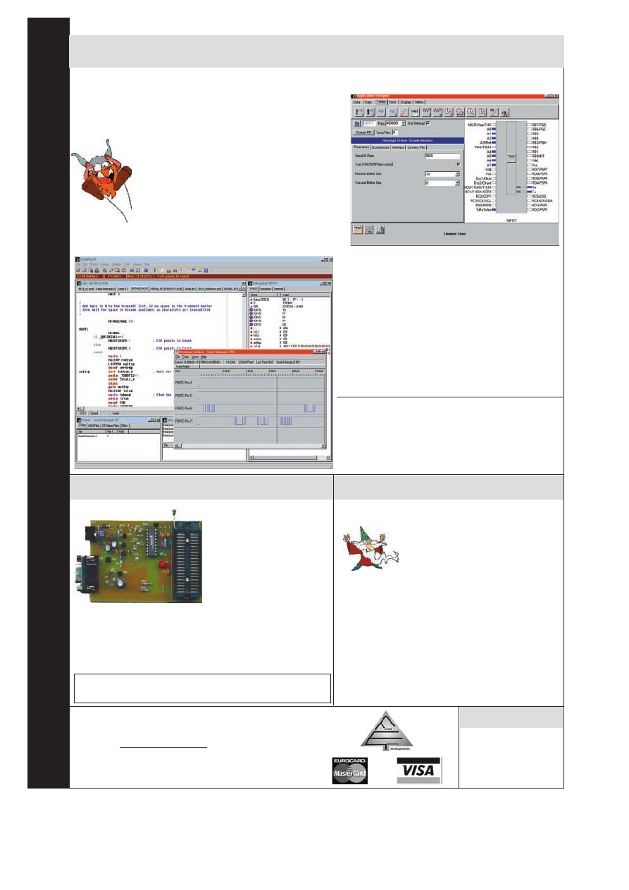
.f
ored.co.uk
Prices full
y
inc
lusive
NEW From FED - PIXIE - Visual PIC C Development
Fully featured C Compiler with drag ’n drop components
PIXIE
) An application designer for the FED PIC C Compiler
FULLY including the PIC C Compiler
) Drag a software component on to your design
) Set up the parameters using check boxes, drop
down boxes and edit boxes (see shot right).
) Connect the component to the PIC pins using the
mouse
) Select your own C functions to be triggered when
events occur (e.g. Byte received, timer overflow etc.)
) Generate the base application automatically and
then add your own functional code
) Supports all 14 bit core PICS, 16F87x, 16C55x,
16C6x, 16F8x, 16C7xx etc.
) Complete development environment includes editor,
compiler, assembler, simulator, waveform analyser,
and terminal emulator. (Screen below)
) Components include -
- Software driven serial interfaces
- Fully buffered hardware driven serial port
with XON/XOFF signalling
- Display drivers - LCD, 7 Segment
- Switches and keypads with debounce/repeat
- Timers and clocks
- I2C, Clocked and Dallas 1 wire buses
- Component and event interfaces to PIC
hardware
) Includes Element editor to create your own
components
) C Compiler designed to ANSI C Standards
) Link into MPLAB
Prices
PIXIE with Introductory manual (C Manuals on CD) - £70
C Compiler with all manuals on CD ROM - £60,
C Compiler manuals (paper copy) - £10.00
Buy PIXIE with WIZPIC or our Programmer - £50.00 CD-ROM
Upgrade - C Compiler users, £15.00
Upgrade - WIZPIC/FED PIC Programmer users, £50.00
PIC & AVR Programmers
PIC Serial Programmer
(Left) including 18Cxxx
Handles serially programmed
PIC devices in a 40 pin multi-
width ZIF socket. 16C55X,
16C6X, 16C7X, 16C8x, 16F8X,
12C508, 12C509, 16C72XPIC
14000, 16F87X, 18Cxxx etc.
Also In-Circuit programming.
Operates on PC serial port
Price :
£45/kit
£50/built & tested
PIC Introductory
– Programs 8 and 18-pin devices : 16C505,
16C55X, 16C61, 16C62X, 16C71, 16C71X, 16C8X, 16F8X, 12C508/9,
12C671/2 £25/kit.
AVR
– AVR1200,2313,4144,8515, 8535, 4434 etc. in ZIF. 4.5V battery
powered. Price: £40 for the kit or £45 built & tested.
All our Programmers operate on PC serial interface. No hard to handle parallel
cable swapping ! Programmers supplied with instructions, + Windows
3.1/95/98/NT software. Upgrade programmers from our web site !
WIZPIC now with 18Cxxx
PIC Visual Development
) Rapid Application Development for
the PIC microcontroller
) Drag and drop your software
component selections on to your
design
) Included components support timers, serial interfaces,
I2C, LCD, 7 Seg displays, keypads, switches, port
controls, and many more.
) Connect software components to PIC pins by point and
click using the mouse
) Set parameters for each component from drop down list
boxes, check boxes, or text entry
) Links your code automatically into library events
) Up to 10 times faster than MPLAB
) Supports all 14 bit core PIC’s – 12C67x, 16C55x, 16C6x,
16C7x, 16C8x, 16C87x, 18Cxxx, etc
Cost – CD-ROM with Data sheets and application notes –
£35.00, Floppy version £30.00.
Forest Electronic Developments
60 Walkford Road, Christchurch, Dorset, BH23 5QG.
Email – info@fored.co.uk, or sales@fored.co.uk
Web Site –
01425-274068 (Voice/Fax)
Prices are fully inclusive, Add £3.00 for P&P and handling to each
order. Cheques/POs payable to Forest Electronic Developments, or
phone with credit card details.
18C452
New architecture (more instructions
+ Hardware multiply), 40MHz clock,
16K program words, 1536 bytes
RAM. Easy to upgrade from 16F877
18C452/JW
£20.00
18C452/OTP
£8.00
106
Everyday Practical Electronics, February 2001
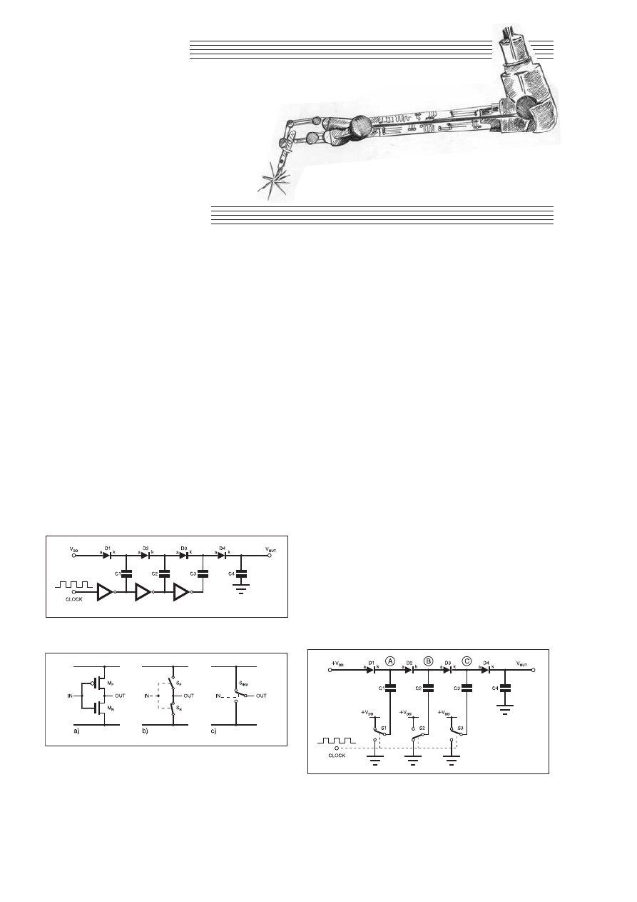
CIRCUIT
SURGERY
The process of charging C2 will actually
discharge C1 to some extent. Thus it will
actually take several clock cycles for C2 to
charge to the point that it has +2 × V
DD
across it. When the clock goes high again,
C1 will again charge to +V
DD
via D1,
replenishing the charge it pumped into C2.
Meanwhile (with clock high), the nega-
tive side of C2 will be connected to +V
DD
so the voltage at point B will be +3 × V
DD
and capacitor C3 will charge to this volt-
age via diode D3, just as C2 charged to +2
× V
DD
via D2. In a similar way C3 will
charge to +4 × V
DD
.
The voltage at point A switches between
V
DD
and +2 × V
DD
, the voltage at B switch-
es between +3 × V
DD
and +2 × V
DD
, and
the voltage at point C switches between +3
xV
DD
and +4 × V
DD
as the clock switches
high to low. In order to get a d.c. output,
diode D4 is used to charge capacitor C4 to
+4 × V
DD
from C3.
Negative output voltages can be obtained
by reversing the diodes in the chain and
connecting the V
in
point to ground. In
practice the output voltages obtained will
be less than those described due to diode
drops and other “losses” in the circuit.
Upstaged Multipliers
This circuit (Fig.1) can be extended by
adding further stages so you can multiply
the input voltage by quite a large amount
(10 or more stages are quite feasible).
The current available from the output
depends on the current available from the
inverters and on the values of the capaci-
tors. If you use 4049s this will be a
couple of milliamps. You can wire
which in turn can be considered as a two-
way switch connecting the output to either
ground (0V) or the positive supply alternate-
ly. Re-drawing Fig.1 in this form results in
the circuit of Fig.3, from which we can see
that one end of each capacitor is alternately
connected to ground and +V
DD
.
How It Works
In the following description of how this
circuit works we’ll ignore diode voltage
drops to keep things simple. In practice
they will mean that the actual voltages are
not quite the exact multiples of the input.
To begin with let’s consider capacitor
C1. When the input clock is high (+V
DD
),
this is inverted by switch S1 which con-
nects one end of C1 to ground (0V), so C1
charges up to +V
DD
.
When the clock goes low again, it is invert-
ed by S1, so the negatively charged plate of
C1 is now at +V
DD
. The voltage that current-
ly exists across C1’s plates means that the
total voltage at point A is pushed up to +2 ×
V
DD
, i.e. a combination of +V
DD
from the
supply, and +V
DD
from C1.
While point A is at +2 V
DD
(i.e. when
the clock is low),
one end of capacitor
C2 is connected to
ground via switch
S2 and the other end
to point B. So C2
will charge to +2 ×
V
DD
with current
flowing from Point
A via D2. During
this time D1 is
reverse biased.
Charge Pumps
V
OLTAGE
multipliers require an a.c.
input, but it is also possible to use
transistors or logic gates to control the
capacitor charging and switching
required for voltage “multiplication”.
Such circuits are called charge pumps
and are, in fact, available as i.c.s, includ-
ing the TPS60100 series from Texas
Instruments. These chips are typically
used for low voltage conversion (e.g.
+1·8V to +5V), or negative supply gener-
ation (e.g. –5V from +5V) and common-
ly they have fixed output voltages.
For non-standard conversions and higher
output voltages, a charge pump can be built
from basic components – an example is out-
lined in Fig.1. In this circuit CMOS inverters
are used to drive a network of capacitors and
diodes to achieve (ideally) a quadrupling of
the input voltage. The circuit is best under-
stood by remembering that CMOS inverters
consist of two transistors in a “push-pull”
configuration such that at a given time only
one transistor is switched on.
This is basically equivalent to two com-
plementary switches, as illustrated in Fig.2,
Regular Clinic
ALAN WINSTANLEY
and IAN BELL
Everyday Practical Electronics, February 2001
107
Our intrepid surgeons pump up the power, plus more on multimeter polarity.
Fig.1. Example circuit of a CMOS inverter-based charge pump
d.c. voltage multiplier. Note V
OUT
is approx. four times V
IN
.
Fig.2. The CMOS inverter (a) can be viewed as two voltage
controlled switches such that when one is on the other is
switched off (b), this in turn can be viewed as a changeover
switch connecting the output to either +V or 0V depending
on the input voltage (c).
Fig.3. The multiplier circuit of Fig.1 re-drawn to show the
switching action of the CMOS inverters in a voltage multiplier.
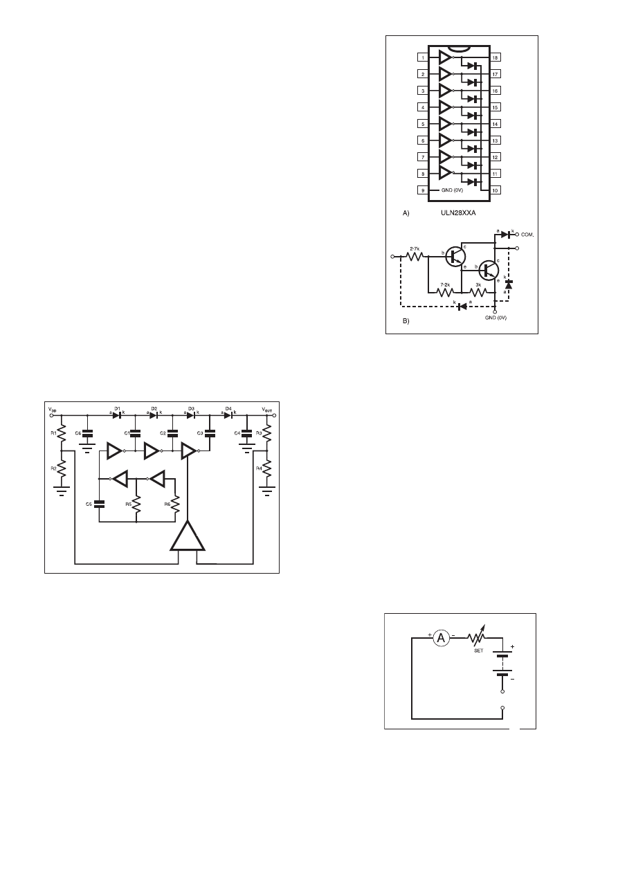
CMOS inverters in parallel to increase
the current capacity.
For a practical circuit you can also consid-
er using an inverter to make a simple CMOS
oscillator to provide the clock for the pump
chain; the frequency is not particularly criti-
cal and should typically be 50kHz to
100kHz. The capacitor values in the charge
pump circuit are also not crucial at this
frequency, 10nF to 100nF should be suitable.
When constructing these circuits you must
take note of the voltage ratings of the capac-
itors – for example do not use a 25V rated
capacitor for an output at 48V! The output
voltage will have some ripple, so the use of a
larger output capacitor will reduce the ripple
voltage. The diodes should be switching
diodes such as 1N4148, rectifier diodes (e.g.
1N4001) are unsuitable.
Making Headroom
One of the problems with this circuit is
poor load regulation – the output voltage
will drop as the load current increases. This
can be overcome using a Zener diode at the
output or by using a simple feedback cir-
cuit as shown in Fig.4.
In this circuit the final stage of the pump
uses a tristate device to allow the pump to be
switched off or isolated by the comparator
when the output reaches a certain voltage.
This voltage should be set to be somewhat
lower than the “open circuit” voltage with no
load and the pump on all the time. This gives
the circuit some “headroom” to cope with
load variations. Notice that we incorporated
a clock circuit as well.
Under very light load conditions the final
stage in Fig.4 will be off most of the time,
with the pump switching on now and then
to replenish the charge in the output capac-
itor. As the load current increases the out-
put capacitor will discharge more rapidly
and the pump will have to be on more often
to keep the output voltage at the required
level. If the load increases further still, the
pump will have to be on all the time, after
which regulation will be lost and the output
voltage will drop as the load increases, just
as it will do with the original circuit.
The values of resistors R1 to R4 are chosen
so that the same voltage appears at the output
of both potential dividers. For example if
V
DD
was +9V and R1 and R2 were equal,
they would produce a +4·5V reference level.
If the desired output was 48V – which is the
value mentioned in the question last month –
R3 and R4 would be selected to give +4·5V
too. The comparator would then switch on
the output stage of the pump when the output
voltage fell below 48V (i.e. the comparator
input fell below 4·5V).
Note that the need for “headroom” for
the regulated circuit will mean the effective
“multiplication factor” for the input to out-
put voltage will be reduced in this version
of the circuit and this should be borne in
mind when deciding how many stages are
required. I.M.B.
Darlington Drivers
I am going to be using a ULN2803A
Darlington array in a forthcoming project. I
am planning initially to use only four of the
transistors, so I would like to know if the
remaining ones should be left open circuit or
connected to V
cc
. John Pickard, by E-mail.
These devices are useful general-purpose
buffers containing eight Darlington transis-
tor drivers which enable higher power (and
higher voltage) loads to be driven directly
by low voltage logic circuits. Each buffer is
rated at 500mA continuous output sink cur-
rent, and you can parallel the outputs to
handle even higher loads: they are ideal for
lamps, l.e.d. arrays, stepper motors etc.
The ULN28xx range pinouts are shown
in Fig.5. They have open-collector outputs,
with built-in clamping diodes for back-
e.m.f. protection – see how all the diode
cathodes (k) are commoned to pin 10. A
dual-in-line package can handle as much as
300 watts of load, provided that the buffers
are strobed at a suitable duty cycle.
I checked the Allegro data book for clues,
and it shows that each buffer has internal
resistors, presumably to make the buffers 5V
TTL/ CMOS compati-
ble. The 2803 uses a
2k7 resistor on each
base,
plus a 10k
divider biasing it to
ground (0V).
On that basis, I
would say that it is
safe to leave device
inputs floating. You
can also download a
data sheet from
Allegro at www.alle-
gromicro.com. ARW.
More on
Multimeters
Following up on
the item on using
multimeters to test
transistors (Circuit
Surgery
October
2000), my thanks to Peter Hemsley who
writes by E-mail:
The polarity of the positive and negative
leads of an analogue meter (i.e. positive
comes out of the negative terminal) are not
as expected due to the simple circuitry
employed and no-one considers it neces-
sary to have extra switching to correct the
polarity. The circuit consists of a current
meter, a variable resistance (to set the
zero) and a battery all in series, so the neg-
ative connection of the meter is connected
to the negative test lead, and the positive
test lead is be connected to the negative of
the battery. Hence the reversal of polarity.
Digital multimeters use a completely dif-
ferent method, the test leads are effectively
connected to the input of the DVM i.c.
measuring voltage.
One method of producing a voltage pro-
portional to resistance is to pass a con-
stant current through the resistor being
measured, but this has the disadvantage
that the current source needs to be stable
and not suffer from drift. The usual way of
measuring resistance is to use the ratio-
metric method, where the resistor being
measured is connected in series with a ref-
erence resistor across a voltage source
(usually a few hundred millivolts).
The resistor under test is connected to
the measuring input and the reference
resistor to the reference input of the DVM
i.c., the resulting reading is then the ratio
of the voltage across the unknown and the
reference resistor. Thus the accuracy of the
reading is determined by only the accura-
cy of the reference resistor.
Thank you for the extra information. For
reference Fig. 6 is the internal circuit of a
typical moving coil resistance meter.
Notice how the battery’s negative terminal
is indeed connected to the positive test
socket. ARW.
108
Everyday Practical Electronics, February 2001
Fig.4. Charge pump circuit with the output regulated to be
a fixed multiple of V
IN
.
Fig.5. (a) Pinout details for the
ULN28XX Darlington array and (b)
basic circuit.
Ω
Fig.6. Internal view of an analogue
multimeter set for resistance measure-
ment. The positive terminal is connect-
ed to the battery negative pole.
+
–
OSCILLATOR
COMPARATOR

W
WH
HE
ET
TH
HE
ER
R E
EL
LE
EC
CT
TR
RO
ON
NIIC
CS
S IIS
S Y
YO
OU
UR
R H
HO
OB
BB
BY
Y
O
OR
R Y
YO
OU
UR
R L
LIIV
VE
EL
LIIH
HO
OO
OD
D .. .. ..
Y
YO
OU
U N
NE
EE
ED
D T
TH
HE
E
M
MO
OD
DE
ER
RN
N E
EL
LE
EC
CT
TR
RO
ON
NIIC
CS
S M
MA
AN
NU
UA
AL
L
a
an
nd
d tth
he
e
E
EL
LE
EC
CT
TR
RO
ON
NIIC
CS
S S
SE
ER
RV
VIIC
CE
E M
MA
AN
NU
UA
AL
L
T
TH
HE
E M
MO
OD
DE
ER
RN
N E
EL
LE
EC
CT
TR
RO
ON
NIIC
CS
S M
MA
AN
NU
UA
AL
L
The essential reference
work for everyone
studying electronics
E
EV
VE
ER
RY
YT
TH
HIIN
NG
G Y
YO
OU
U N
NE
EE
ED
D T
TO
O G
GE
ET
T
S
ST
TA
AR
RT
TE
ED
D A
AN
ND
D G
GO
O F
FU
UR
RT
TH
HE
ER
R IIN
N E
EL
LE
EC
CT
TR
RO
ON
NIIC
CS
S!!
The revised edition of the Modern Electronics Base Manual
contains practical, easy-to-follow information on the following
subjects:
BASIC PRINCIPLES:
Electronic Components and their
Characteristics (16 sections from Resistors and Potentiometers to
Crystals, Crystal Modules and Resonators), Circuits Using Passive
Components (9 sections), Power Supplies, The Amateur
Electronics Workshop, The Uses of Semiconductors, Digital
Electronics (6 sections), Operational Amplifiers, Introduction to
Physics, Semiconductors (6 sections) and Digital Instruments
(5 sections).
CIRCUITS TO BUILD:
There's nothing to beat the satisfaction of
creating your own project. From basic principles, like soldering and
making printed circuit boards, to circuit-building, the Modern
Electronics Manual and its Supplements describe clearly, with
appropriate diagrams, how to assemble radios, loudspeakers,
amplifiers, car projects, computer interfaces, measuring
instruments, workshop equipment, security systems, etc.
The Base Manual describes 13 projects including a Theremin and
a Simple TENS Unit.
ESSENTIAL DATA:
Extensive tables on diodes, transistors,
thyristors and triacs, digital and linear i.c.s.
EXTENSIVE GLOSSARY:
Should you come across a technical
word, phrase or abbreviation you're not familiar with, simply turn
to the glossary included in the Manual and you'll find a
comprehensive definition in plain English.
The Manual also covers
Safety
and
Suppliers.
The most comprehensive reference work ever produced at a price
you can afford, the revised edition of THE MODERN
ELECTRONICS MANUAL provides you with all the
essential
information you need.
T
TH
HE
E M
MO
OD
DE
ER
RN
N E
EL
LE
EC
CT
TR
RO
ON
NIIC
CS
S M
MA
AN
NU
UA
AL
L
Revised Edition of Basic Work: Contains over 900 pages of information. Edited by John Becker.
Regular Supplements: Approximately 160-page Supplements of additional information which, if requested, are forwarded to you
immediately on publication (four times a year). These are billed separately and can be discontinued at any time.
Presentation: Durable looseleaf system in large A4 format
Price of the Basic Work: £39.95 SALE PRICE £23.97 (to include a recent Supplement FREE)
Our 30 day money back guarantee gives you complete peace of mind. If you are not entirely happy with either
Manual, for whatever reason, simply return it to us in good condition within 30 days and we will make a full refund
of your payment – no small print and no questions asked.
(Overseas buyers do have to pay the overseas postage charge)
Wimborne Publishing Ltd., Dept Y1, Allen House, East Borough, Wimborne, Dorset BH21 1PF. Tel: 01202 881749. Fax: 01202 841692.
Guarantee
SALE
4
40
0%
%
O
OF
FF
F
Buy either Man
ual at 40% off
regular price
.
Or b
uy both and sa
ve even more
.
DON’T
MISS
THIS!
)
Over 900 pages
)
In-depth theory
)
Projects to build
)
Detailed assembly instructions
)
Full components checklists
)
Extensive data tables
)
Detailed supply information
)
Easy-to-use format
)
Clear and simple layout
)
Comprehensive subject range
)
Professionally written
)
Regular Supplements
)
Sturdy gold blocked ring-binder

E
EL
LE
EC
CT
TR
RO
ON
NIIC
CS
S S
SE
ER
RV
VIIC
CE
E M
MA
AN
NU
UA
AL
L
E
EV
VE
ER
RY
YT
TH
HIIN
NG
G Y
YO
OU
U N
NE
EE
ED
D T
TO
O K
KN
NO
OW
W T
TO
O G
GE
ET
T S
ST
TA
AR
RT
TE
ED
D IIN
N
R
RE
EP
PA
AIIR
RIIN
NG
G A
AN
ND
D S
SE
ER
RV
VIIC
CIIN
NG
G E
EL
LE
EC
CT
TR
RO
ON
NIIC
C E
EQ
QU
UIIP
PM
ME
EN
NT
T
SAFETY: Be knowledgeable about Safety Regulations, Electrical Safety and First Aid.
UNDERPINNING KNOWLEDGE: Specific sections enable you to Understand Electrical
and Electronic Principles, Active and Passive Components, Circuit Diagrams, Circuit
Measurements, Radio, Computers, Valves and manufacturers' Data, etc.
PRACTICAL SKILLS: Learn how to identify Electronic Components, Avoid Static
Hazards, Carry Out Soldering and Wiring, Remove and Replace Components.
TEST EQUIPMENT: How to Choose and Use Test Equipment, Assemble a Toolkit, Set
Up a Workshop, and Get the Most from Your Multimeter and Oscilloscope, etc.
SERVICING TECHNIQUES: The regular Supplements include vital guidelines on how to
Service Audio Amplifiers, Radio Receivers, TV Receivers, Cassette Recorders, VIdeo
Recorders, Personal Computers, etc.
TECHNICAL NOTES: Commencing with the IBM PC, this section and the regular
Supplements deal with a very wide range of specific types of equipment – radios, TVs,
cassette recorders, amplifiers, video recorders etc..
REFERENCE DATA: Detailing vital parameters for Diodes, Small-Signal Transistors,
Power Transistors, Thyristors, Triacs and Field Effect Transistors. Supplements include
Operational Amplifiers, Logic Circuits, Optoelectronic Devices, etc.
The essential work for
servicing and repairing
electronic equipment
)Around 900 pages
)Fundamental principles
)Troubleshooting techniques
)Servicing techniques
)Choosing and using test
equipment
)Reference data
)Easy-to-use format
)Clear and simple layout
)Vital safety precautions
)Professionally written
)Regular Supplements
)Sturdy gold blocked ring-binder
E
EL
LE
EC
CT
TR
RO
ON
NIIC
CS
S S
SE
ER
RV
VIIC
CE
E M
MA
AN
NU
UA
AL
L
Basic Work: Contains around 900 pages of information. Edited by Mike Tooley BA
Regular Supplements: Approximately 160-page Supplements of additional information which, if requested, are forwarded to you
immediately on publication (four times a year). These are billed separately and can be discontinued at any time.
Presentation: Durable looseleaf system in large A4 format
Price of the Basic Work: £39.95 SALE PRICE £23.97 (to include a recent Supplement FREE)
O
OR
RD
DE
ER
R B
BO
OT
TH
H M
MA
AN
NU
UA
AL
LS
S T
TO
OG
GE
ET
TH
HE
ER
R A
AN
ND
D S
SA
AV
VE
E A
AN
NO
OT
TH
HE
ER
R £
£8
8
A
A m
ma
as
ss
s o
off w
we
ellll--o
orrg
ga
an
niis
se
ed
d a
an
nd
d c
clle
ea
arrlly
y e
ex
xp
plla
aiin
ne
ed
d iin
nffo
orrm
ma
attiio
on
n iis
s b
brro
ou
ug
gh
htt tto
o y
yo
ou
u b
by
y e
ex
xp
pe
errtt e
ed
diitto
orriia
all
tte
ea
am
ms
s w
wh
ho
os
se
e c
co
om
mb
biin
ne
ed
d e
ex
xp
pe
erriie
en
nc
ce
e e
en
ns
su
urre
es
s tth
he
e w
wiid
de
es
stt c
co
ov
ve
erra
ag
ge
e
R
Re
eg
gu
ulla
arr S
Su
up
pp
plle
em
me
en
ntts
s tto
o tth
he
es
se
e u
un
niiq
qu
ue
e p
pu
ub
blliic
ca
attiio
on
ns
s,, e
ea
ac
ch
h a
arro
ou
un
nd
d 1
16
60
0 p
pa
ag
ge
es
s,, k
ke
ee
ep
p y
yo
ou
u a
ab
brre
ea
as
stt o
off
tth
he
e lla
atte
es
stt tte
ec
ch
hn
no
ollo
og
gy
y a
an
nd
d tte
ec
ch
hn
niiq
qu
ue
es
s iiff rre
eq
qu
uiirre
ed
d
Unlike a book or encyclopedia, these Manuals
are living works – continuously extended with
new material. If requested, Supplements are sent
to you approximately every three months. Each
Supplement contains around 160 pages – all for
only £23.50+£2.50 p&p. You can, of course,
return any Supplement (within ten days) which
you feel is superfluous to your needs. You can
also purchase a range of past Supplements to
extend your Base Manual on subjects of
particular interest to you.
We are able to provide you with the most
important and popular, up to date, features in our
Supplements. Our unique system is augmented
by readers' requests for new information.
Through this service you are able to let us know
exactly what information you require in your
Manuals.
You can also contact the editors directly in writing
if you have a specific technical request or query
relating to the Manuals.
REGULAR SUPPLEMENTS
RESPONDING TO YOUR NEEDS
PLEASE
send me
$
THE MODERN ELECTRONICS MANUAL plus a FREE SUPPLEMENT
$
ELECTRONICS SERVICE MANUAL plus a FREE SUPPLEMENT
I enclose payment of £23.97 (for one Manual) or £39.94 for both Manuals (saving
another £8 by ordering both together) plus postage if applicable.
I also require the appropriate Supplements four times a year. These are billed
separately and can be discontinued at any time.
(Please delete if not required.)
Should I decide not to keep the Manual/s I will return it/them to you within 30 days for a
full refund.
FULL NAME . . . . . . . . . . . . . . . . . . . . . . . . . . . . . . . . . . . . . . . . . . . . . . . . . . . . . . . . . . . . .
ADDRESS . . . . . . . . . . . . . . . . . . . . . . . . . . . . . . . . . . . . . . . . . . . . . . . . . . . . . . . . . . . . . .
. . . . . . . . . . . . . . . . . . . . . . . . . . . . . . . . . . . . . . . . . . . . . . . . . . . . . . . . . . . . . . . . . . . . . . .
. . . . . . . . . . . . . . . . . . . . . . . . . . . . . . . . . . . . . . . . . . . .POSTCODE . . . . . . . . . . . . . . . . .
SIGNATURE . . . . . . . . . . . . . . . . . . . . . . . . . . . . . . . . . . . . . . . . . . . . . . . . . . . . . . . . . . . . .
$
I enclose cheque/PO payable to Wimborne Publishing Ltd.
$
Please charge my Visa/Mastercard/Switch Switch Issue No . . . . . . . . . . . . . . . .
Card No. . . . . . . . . . . . . . . . . . . . . . . . . . . . . . . . . . . . . . . . Card Exp. Date . . . . . . . . . . .
POSTAGE CHARGES
Price PER MANUAL
Postal Region
Surface
Air
Mainland UK
FREE
–
Scottish Highlands,
UK Islands & Eire
£5.50 each
–
Europe (EU)
–
£20 each
Europe (Non-EU)
£20 each
£26 each
USA & Canada
£25 each
£33 each
Far East & Australasia
£31 each
£35 each
Rest of World
£25 each
£45 each
Please allow four
working
days for UK delivery.
NOTE: Surface mail can take over 10 weeks to some parts of
the world. Each Manual weighs about 4kg when packed.
ORDER FORM
Simply complete and return the order form with your
payment to the following address:
Wimborne Publishing Ltd, Dept. Y1, Allen House,
East Borough, Wimborne, Dorset BH21 1PF
We offer a 30 day MONEY BACK
GUARANTEE
– if you are not happy with either Manual simply return it to
us in good condition within 30 days for a full refund.
Overseas buyers do have to pay the overseas postage – see below.
(PLEASE PRINT)
esm2
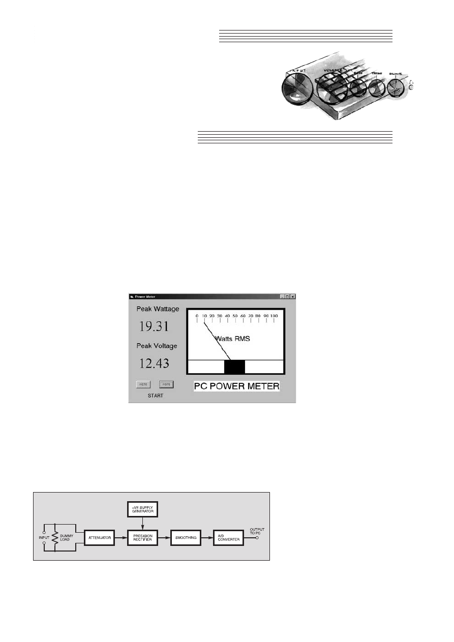
CCoonnssttrruuccttiioonnaall PPrroojjeecctt
T
HIS
project is the latest in the occa-
sional series of PC-based test equip-
ment. Previous units were based on
circuits from the Interface series of arti-
cles. This device is based on an analogue-
to-digital converter (ADC) featured in the
series, but it is otherwise original.
It enables a PC to measure power, and it
is primarily intended for use with audio
power amplifiers. However, the interface
uses d.c. coupling and it could probably be
modified for use in some d.c. power mea-
suring applications.
When used for audio power
measurement it provides an 8
9
dummy load, and shows the peak
power and voltage delivered to the
load. It also has a virtual panel
meter that shows the r.m.s. power
level when using sinewave test sig-
nals. With sinewave test signals the
r.m.s. power level is easily calculat-
ed, since it is exactly half the peak
power level.
The 12-bit ADC is scaled to read
voltages from 0V to 40·95V. With
40 volts into an 8
9 load it equates
to 200 watts (40 × 40 = 1600,
1600/8 = 200), or 100 watts r.m.s.
when using a sinewave test signal.
The 8
9 dummy load can handle a
little over 100 watts r.m.s. provided
it is equipped with adequate heatsinking.
The circuit connects to the printer port
of the host PC, and the port does not need
to be a bidirectional type. The power meter
program is written in Visual Basic 6, and it
requires Windows 95, 98 or ME to run.
Note that it will not work with other
versions of Windows. Visual Basic 6
produces programs that are incompatible
with 16-bit versions of Windows such as
version 3.1. Windows NT and 2000 do not
permit the form of direct port access,
which is essential to the operation of this
software.
DUMMY LOAD
The block diagram of Fig.1 shows the
system used in the PC Audio Power Meter.
The input signal is connected to a dummy
load, which is simply an 8
9 resistor that
takes the place of a loudspeaker. This
avoids having unduly loud test tones com-
ing from a loudspeaker used as the load,
and it also simplifies measurements.
The main problem with using a loud-
speaker as the load is that its actual imped-
ance can vary considerably from its nomi-
nal figure of 8
9. The actual impedance
tends to vary significantly with changes in
the input frequency. Measurements made
on the assumption of an 8
9 load imped-
ance could have huge errors if the imped-
ance of the loudspeaker was actually more
like 6
9or 129 at the test frequency.
Another problem in using a loudspeaker
as the load is that the load would not be
purely resistive. There would also be ele-
ments of capacitance and inductance, and
this slightly complicates matters. With a
load that is pure resistance the output cur-
rent is precisely in-phase with the output
voltage.
PEAK PRACTICE
In order to calculate the peak output
power it is merely necessary to measure
the peak output voltage. From this voltage
and the load resistance it is possible to cal-
culate the output power using the
method used previously (square the
voltage and divide this figure by the
load resistance).
Things are more complicated
when using a loudspeaker as the
load. Because the precise imped-
ance is an unknown quantity, the
output voltage and current must
both be measured. Simply multi-
plying the peak voltage by the
peak current may not give an
accurate figure for peak power,
because maximum current might
not coincide with maximum
voltage.
With capacitance and inductance
in the load there are so-called imag-
inary currents to deal with, as well
as the real currents. The point to
remember here is that current can
flow into and out of theoretically perfect
capacitors and inductors, but they do not
dissipate any power. To be sure of accurate
results the output current and voltage must
be continuously sampled and processed by
a multiplier circuit to produce a power
reading that is always accurate. The peak
reading from the multiplier will truly
reflect the peak output power from the
amplifier.
SYSTEM OPERATION
To avoid complications and ensure consis-
tent test conditions, most audio power ampli-
fier testing is undertaken using a dummy
load resistor. For the reasons outlined previ-
ously, it is essential to the operation of this
power measuring system that the load is a
resistor and not a loudspeaker.
The signal fed to the load is also fed to
an attenuator that is used to give the correct
PC AUDIO
POWER METER
PC computer interface for
measuring power output from
audio amplifiers
112
Everyday Practical Electronics, February 2001
ROBERT PENFOLD
Fig.1. Block diagram for the PC Audio Power Meter system.
Virtual screen display of the PC Power Meter.
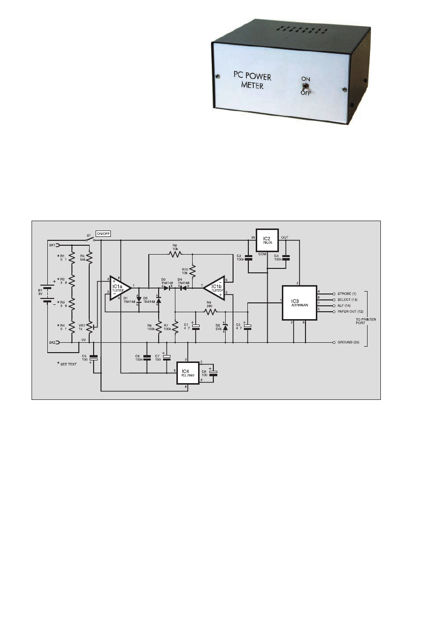
scaling. The ADC has a full-scale reading
of 4095, which is achieved at an input
potential of 5V. By reducing the input
potential by a ratio of a little over 7-to-1
the full-scale input voltage of the circuit as
a whole is increased to the required figure
of 40·95. The attenuation is adjustable so
that the unit can be calibrated against an
accurate reference voltage.
With symmetrical waveforms it is only
necessary to measure the peak positive or
negative input voltage, but not both as they
will be the same. With asymmetric wave-
forms there can be a substantial difference
between the peak positive and negative
voltages, making it necessary to measure
both in order to guarantee accurate results.
In this unit the output of the attenuator is
fed to a precision full-wave rectifier so that
both sets of half-cycles are measured. The
rectifier circuit requires a negative supply,
and this is derived from the 9V battery via
a simple switch-mode circuit.
The output of the rectifier feeds a
smoothing circuit that has a short attack
time and a much longer decay period. The
effect of this is very much like a peak-hold
circuit, with a d.c. output voltage that is
equal to the peak input potential.
The ADC is a 12-bit type that uses serial
interfacing to the PC. This enables 12-bit
values to be read by way of just two input
lines and two output types. Four of the
printer port’s handshake lines are adequate
to provide the interfacing, making it unnec-
essary for the port to have bidirectional
data lines.
CIRCUIT OPERATION
The full circuit diagram for the PC
Audio Power Meter appears in Fig.2. The
required value for the dummy load is 8
9,
but this is not a “preferred” value. To make
up the value of 8
9, four resistors (R1 to
R4) are connected in series. R2 and R3
provide most of the resistance and there-
fore have to dissipate most of the power.
Accordingly, they have power ratings of 50
watts each.
Resistors R1 and
R4 each take little
more than one percent
of the total power fed
to the load, and a rat-
ing of two or three
watts is therefore ade-
quate for these.
The input attenua-
tor consists of fixed
resistor R5 and preset
VR1. The latter
enables the full-scale
sensitivity to be
adjusted so that the
unit can be accurately
calibrated.
IC1 is a dual operational amplifier and it
is used in the precision rectifier. Simply
feeding the signal through a diode does not
give the desired result due to the non-lin-
earity of all semiconductor diodes. An
ordinary silicon diode requires a forward
bias of about 0·6V before it will start to
conduct significantly, and the forward
resistance then plummets with only a small
increase in the applied voltage.
This means that around 0·6V is needed
before any output signal is produced, and
at higher input potentials the output volt-
age is about 0·6V or so lower than it should
be. There are diodes that offer lower for-
ward voltage drops, but none give adequate
performance where good linearity is
required.
The standard solution to the problem is
to include two diodes in the negative feed-
back circuit of a non-inverting amplifier. In
this case the diodes are D1 and D2, and the
amplifier is IC1a. At input potentials of
less than about 0·6V there is no significant
feedback through D1 and D2, which results
in IC1 operating at its open loop voltage
gain.
This gain is very high, so only a small
input voltage is needed to send the output
about 0·6V positive or negative. Diode D1
then starts to apply strong negative feed-
back if the output goes positive, or D2
applies the feedback if the output goes neg-
ative. This gives what is virtually a stan-
dard voltage follower circuit, but the output
signal, whatever its polarity, is boosted by
about 0·6V.
On positive half cycles D3 feeds the out-
put signal to the smoothing circuit. The
voltage added at the output of IC1a by D1
counteracts the losses through D3, giving
accurate half-wave rectification via IC1a
and D3. IC1b operates as an inverting
amplifier having unity voltage gain, and
this inverts the output signal from IC1a. On
negative input half cycles the output of
IC1b therefore produces positive half
cycles that are fed to the smoothing circuit
via diode D4.
The negative voltage added at the output
of IC1a by D2 produces a positive voltage
at the output of IC1b. This voltage counter-
acts the voltage drop through D4, giving
the required precision rectification. The
combined output of D3 and D4 does, of
course, provide full-wave rectification.
The smoothing circuit has the smoothing
capacitance provided by C1 and C2 in par-
allel. The low source impedance of the rec-
tifier circuit provides a fast attack time, but
the high value of resistor R7 produces a
much slower decay time.
The value of the smoothing capacitance
has to be a compromise. A high value is
needed in order to avoid jittery readings at
Everyday Practical Electronics, February 2001
113
Ω
Ω
Ω
Ω
Ω
µ
µ
µ
µ
µ
Fig.2. Complete circuit diagram for the PC Audio Power Meter. Note that resistors R1 to R4 must be high wattage types.
IN
IN

low frequencies, but also makes the unit
slow to respond to a reduction in power
level. The specified values for C1 and C2
represent something close to the minimum
that should be used. Resistor R9 and diode
D5 form a protection circuit that limits the
input voltage to the converter to about
–0·65 volts and +5·6 volts.
DIGITAL CONVERSION
The ADC device, IC3, requires no dis-
crete components. It requires a 5V sup-
ply, and this is derived from the 9V bat-
tery by way of a 5V monolithic voltage
regulator (IC2). The full-scale input volt-
age of the converter is equal to the supply
potential.
The chip interfaces to the PC via a
simple four-wire serial system. The com-
puter pulses pin 7 low to start a conver-
sion and then monitors pin 8, which goes
low when the conversion has been
completed.
The first bit is then read from pin 5, a
clock pulse is supplied to pin 4, the next
bit is read from pin 5, another pulse is
supplied to pin 4, and so on until 16 bits
have been read. Note, though, that the
first four bits are always at zero, and that
the converter only provides 12 valid bits
of data.
The negative supply for IC1 is provided
by a simple switch-mode power supply
based on IC4. This chip uses a d.p.d.t. elec-
tronic switch to first connect C8 to the 9V
supply, and then connect it to the output.
The switching is arranged so that a nega-
tive supply is produced on smoothing
capacitor C7, and despite losses through
IC4 the negative supply voltage is only
marginally lower than the positive supply
potential.
There is a slight imbalance in the supply
potentials, but the difference is not large
enough to be of any practical consequence.
The current consumption of the entire cir-
cuit is about 8mA to 10mA. A PP3-size
battery is just about adequate to supply
this, but six AA size cells in a holder is a
more practical choice if the unit will
receive a great deal of use.
CONSTRUCTION
Most of the components are assembled
on a stripboard that measures 39 holes by
20 copper strips. This can conveniently be
cut from a standard 39 by 29 or 39 by 39
stripboard. The component layout for the
board and the underside view showing the
breaks in the copper strips are given in
Fig.3.
Construction follows along the usual
lines with the two mounting holes being
drilled in the board, the breaks being
made in the strips, and then the compo-
nents and link wires are fitted. The chips
used for IC3 and IC4 are MOS types that
require the standard anti-static handling
precautions.
In particular, they must be fitted in hold-
ers (sockets), and the use of a holder for
IC1 is also recommended.
Do not fit the integrated circuits into the
holders until all the wiring has been com-
pleted, and try to touch the pins as little as
possible. Keep the integrated circuits away
from any likely sources of strong static
charges.
The link-wires are made from 22 or 24
s.w.g. tinned copper wire. It is a good
idea to insulate the longer wires with
p.v.c. sleeving to ensure that there are no
accidental short-circuits. Fit single-sided
solder pins at the points where connec-
tions to the off-board components such
as SK1 and SK2 will be made.
Generously tin the tops of the pins with
solder, and it should then be easy to
make reliable connections to them
later on.
114
Everyday Practical Electronics, February 2001
Fig.3. Stripboard compo-
nent layout, interwiring and
details of breaks required
in the copper tracks. Note
the heavy-duty, high cur-
rent wire link across the
“free ends’’ of resistors R2
and R3.
Component layout on the completed circuit board.
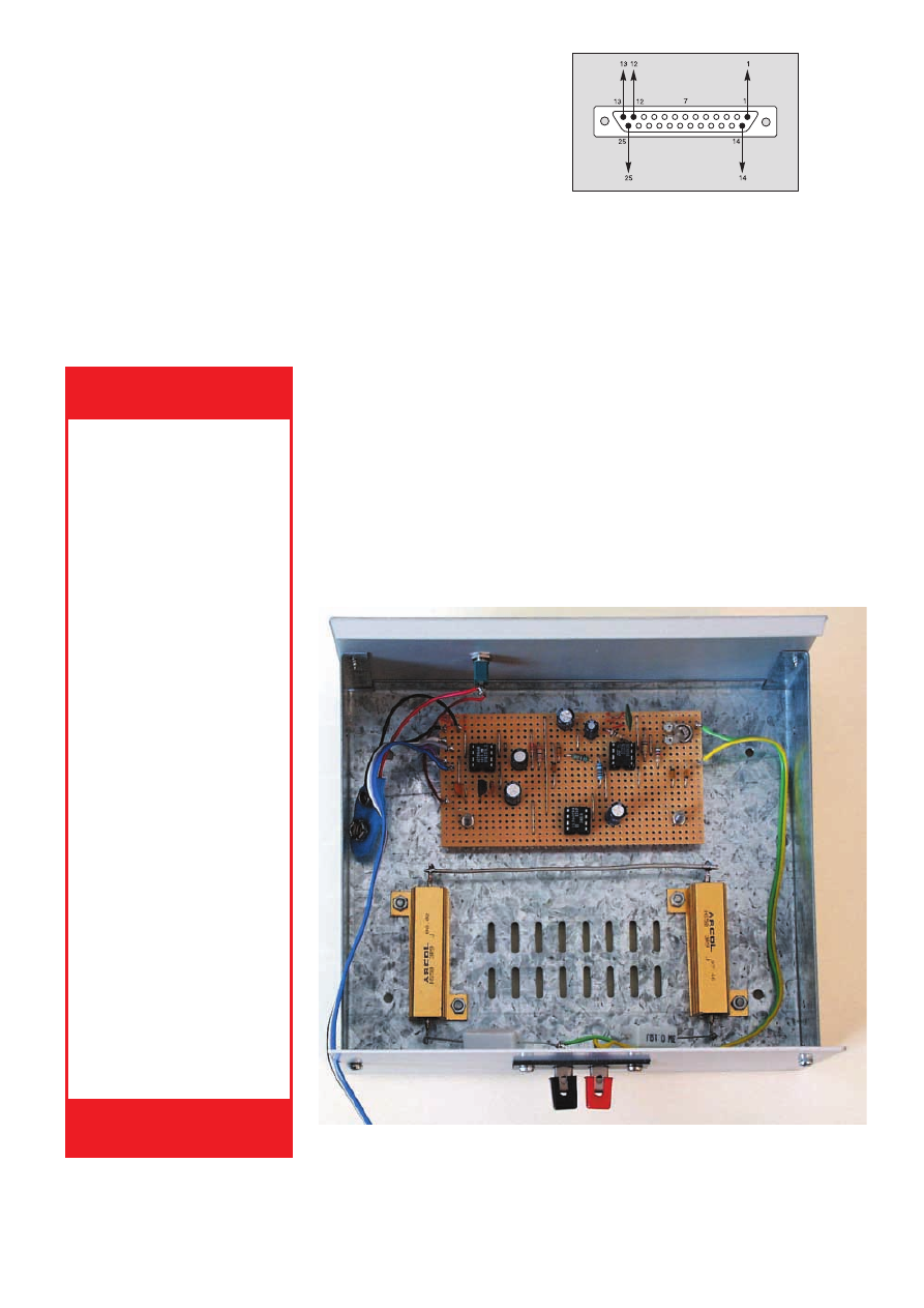
Everyday Practical Electronics, February 2001
115
compound to ensure that there is a good
thermal contact between the resistors and
the heatsink or chassis.
The fixings for the circuit board must
include spacers about 6mm or more in
length so that the connections on the
underside of the board are kept well clear
of the metal case.
Switch S1 is mounted at any convenient
point on the front panel. SK1 and SK2
must be heavy-duty sockets that are capa-
ble of handling the high currents involved
in this application. The types of connector
that are normally used for loudspeaker out-
puts are the best choices, such as terminal
posts or heavy-duty spring terminals.
Resistors R1 and R4 are connected
between the sockets and the two high-
power resistors, as shown in Fig.3. A wire
to connect R2 and R3 is also needed, and is
included in Fig.3, as is all the hard wiring.
This wire carries high currents of up to
about 5A r.m.s. and a fairly heavy gauge of
wire must therefore be used. Ordinary
hook-up wire is suitable for the connec-
tions from sockets SK1 and SK2 to the
circuit board, since this is a low current
connection.
LINKING-UP
The easiest way to make the connections
to the printer port of the PC is to hard wire
one end of the cable to the circuit board,
and to connect the other end to a 25-way
male D-type connector. This type of con-
nector is the standard type for the printer
ports of desktop PCs. Virtually any 5-way
cable is suitable, but about one metre of
ribbon cable is probably the best choice.
The pin numbering and connections to
the 25-way connector are shown in Fig.4,
which shows the connector viewed from
the rear (i.e. the side to which the connec-
tions are made). An exit slot for the cable
must be filed in one side of the rear panel.
The alternative method is to wire the
circuit board to a 25-way D-connector fit-
ted on the rear panel. The interface is then
connected to the PC via a suitable 25-way
D-connector lead. This is in some ways
the neater way of doing things, but is more
difficult and expensive to implement.
Also, great care has to be taken to ensure
that all the connections are carried
through correctly to the PC.
CALIBRATION
AND USE
Since the unit is d.c. coupled, the easi-
est calibration method is to feed the input
from a bench power supply unit. An accu-
rate multimeter is used to set a known out-
put voltage, and preset VR1 is then adjust-
ed to give the appropriate voltage reading
ENCLOSURE
A metal case must be used for this
project due to the substantial amount of
heat generated by R2 and R3 when mea-
suring high power levels. Note that these
resistors can only be used continuously at
their rated powers if they are fitted on sub-
stantial heatsinks rated at about 3°C per
watt.
Provided the unit is housed in a reason-
ably large metal case having ventilation
grilles the case should provide adequate
heatsinking. If it is likely that the unit will
be used with high output powers for long
periods it is safer to fit the resistors onto
large heatsinks.
The resistors, with or without heatsinks,
are fitted on the base panel of the case near
the rear of the unit, leaving sufficient space
for the circuit board at the front (see pho-
tograph). It is advisable to use heatsink
Approx. Cost
Guidance Only
£
£2
27
7
excluding case & batt.
Resistors
R1, R4
0
W
1 3W 5% wirewound
(2 off)
R2, R3
3
W
9 50W wirewound
(2 off)
R5
5k6 0·25W 5% carbon
film
R6, R7
100k 0·25W 5%
carbon film (2 off)
R8, R10
10k 0·6W 1% metal
film (2 off)
R9
390
W
0·25W 5%
carbon film
Potentiometer
VR1
1k miniature
preset,
horizontal
Capacitors
C1, C2
4
m7 radial elect. 50V
(2 off)
C3, C4,
100n disc ceramic
C6
(3 off)
C5, C7, C8 100
m radial elect. 10V
(3 off)
Semiconductors
D1 to D4
1N4148 signal diode
(4 off)
D5
5V6 400mW Zener
diode
IC1
TL072CP dual op.amp
IC2
78L05 +5V 100mA
voltage regulator
IC3
AD7896AN 12-bit ADC
IC4
ICL7660 voltage
converter
Miscellaneous
S1
s.p.s.t. min. toggle
switch
B1
9V battery (PP3 type
– see text)
SK1, SK2
spring terminals
(see text)
Metal case, 175mm x 160mm x 85mm
(approx); 0·1-inch matrix stripboard, 39
holes x 20 strips; 8-pin d.i.l. socket (3
off); battery connector; 25-pin male D-
type connector and 5-way lead (see
text); connecting wire; fixings; solder, etc.
COMPONENTS
See
S
SH
HO
OP
P
T
TA
AL
LK
K
p
pa
ag
ge
e
Fig.4. The five connections to the 25-
way male D-connector.
General internal layout of components inside the metal case. The high power resis-
tors (R2, R3) are bolted to the metal base panel, either side of the vent slots.
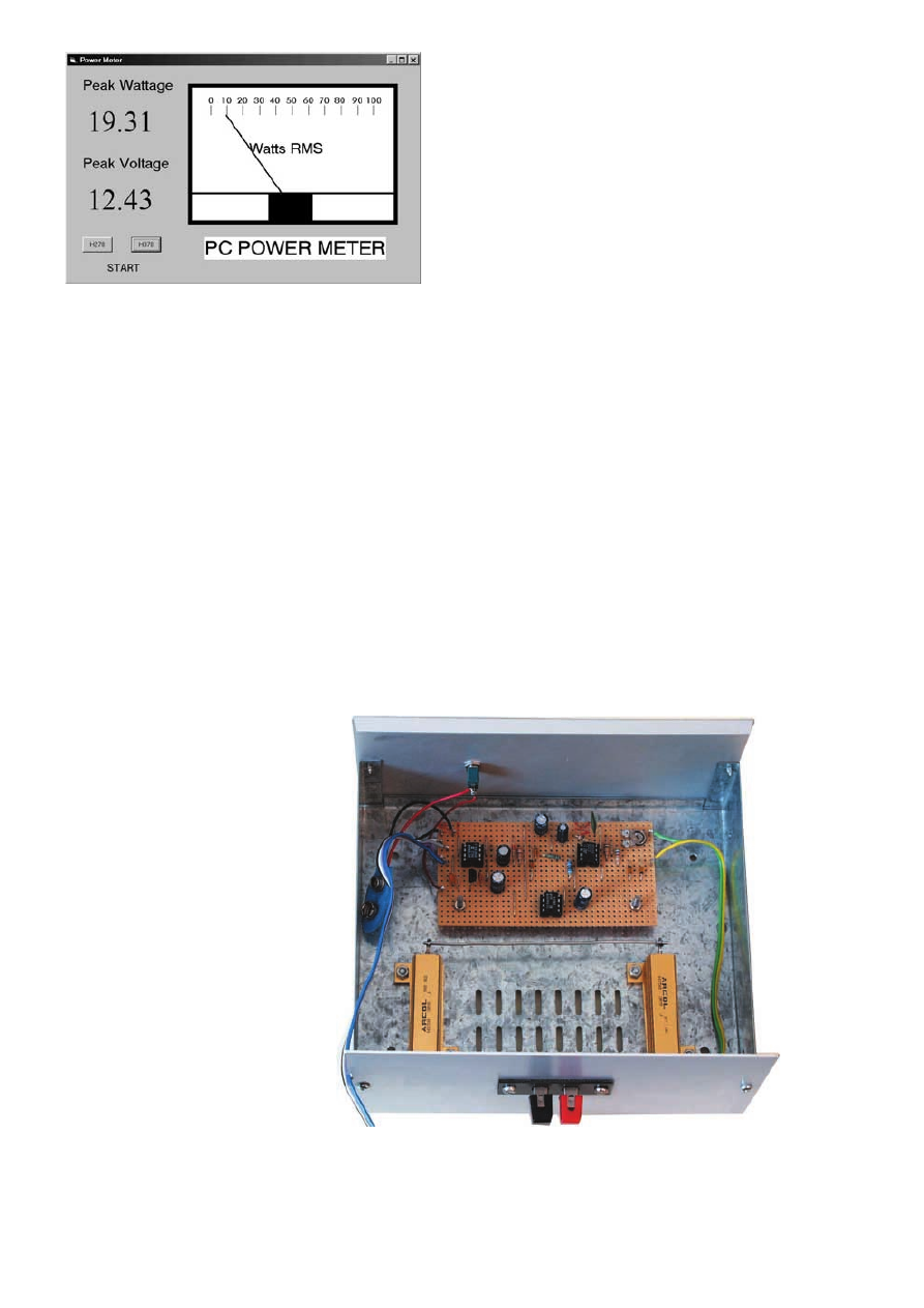
from the on-screen voltage display. Bear in
mind that the dummy load will give quite
high current flows when using even quite
low input voltages. If loading of the power
supply is a problem, temporarily discon-
nect the dummy load while the unit is
calibrated.
Also bear in mind that one input socket
(SK2) connects to earth. If one output of
the power supply is also earthed it is essen-
tial to connect the supply with the correct
polarity or it will be short-circuited.
When testing most ready-made ampli-
fiers it does not matter which way round
the outputs are connected to the inputs of
the power meter interface. Ready-made
amplifiers usually have double insulation
and no connection to the mains earth lead.
It would clearly be prudent to check this
point before connecting an amplifier to the
interface. If one output is connected to the
mains earth lead, then this output must
connect to the earth rail of the interface,
which will almost certainly be earthed via
the PC.
Home constructed power amplifiers that
are mains powered normally have one out-
put connected to the mains earth, and it is
then imperative that this output connects to
the earth rail of the interface. Home built
amplifiers that use the bridging technique
usually have an earthed chassis, but neither
output connected to earth. Amplifiers of
this type must not be used with this
interface, and very high output currents
would flow if they were connected to the
unit.
FOUR-OHM LOAD
It is easy to modify the unit to provide a
4
9 load. The simplest method is to replace
R1 and R2 with a shorting link, or to have
a heavy duty switch connected across them
so that the unit can be switched from 8
9 to
4
9 operation. Obviously this method
halves the power rating of the dummy load
to a little over 50 watts.
The alternative is to add another set of
four resistors in parallel with the existing
dummy load. These could be connected
via a heavy-duty switch to permit switch-
ing between 4
9 and 89 operation. The
advantage of this method is that the power
rating of the dummy load is doubled when
the extra resistors are used. Of course, a
given input voltage produces double the
current flow and power level when a 4
9
load is used. The digital display will then
read equivalent r.m.s. power and not the
peak power level.
PROGRAM
OPERATION
A screen dump of
the program in opera-
tion is shown in
Fig.5. Clicking on
either of the buttons
sets the printer port
address range used
and starts the pro-
gram. Printer port 1 is
normally at base
address H378, and
port 2 is usually at
H278.
The digital read-
outs provide readings
of peak power and
voltage, and the ana-
logue readout on a virtual panel meter
gives the equivalent r.m.s. power value.
Note that the r.m.s. reading is only valid
when using sinewave test signals with no
serious clipping of the output signal.
The routine that reads the converter and
updates the displays is assigned to a timer.
Initially the timer is disabled, but operating
one of the command buttons assigns the
appropriate values to the variables that
store the port addresses and then enables
the timer. The routine assigned to the timer
starts by generating a pulse to start a con-
version. A hold-off is then needed to allow
time for the conversion to be completed.
This can be provided by monitoring the
Busy output of the converter, which goes
low when a conversion has been complet-
ed. This method was used for previous
EPE designs that used the AD7896 con-
verter chip, but it seems to result in the
program tending to hang when used with
some printer ports.
The Busy line is connected to the print-
er port so that this method can be tried by
those who like to “do their own thing”, but
the use of a delay loop seems to be the
safer option. This is the method used here,
and the delay subroutine is also used to
lengthen all the control signals from the
computer. This reduces the risk of prob-
lems with stray coupling in the connecting
cable.
Next the data is clocked out, read bit by
bit, and assembled into a 12-bit value.
Dividing the value from the converter by
800 and 100 respectively provides the cur-
rent and voltage readings. The software
provides no current readout, but this value
is available in the Current variable for any-
one who wishes to use it in his or her own
version.
Multiplying the current and voltage
readings provides the measured power
level, and some further mathematics then
limits readings to a manageable two deci-
mal places. Some further mathematics then
produce a value that can be used as the X2
co-ordinate of Line1, which is the pointer
of the virtual panel meter.
OBTAINING SOFTWARE
The PC Audio Power Meter’s software
is available from the EPE web site (free) or
from the Editorial Office (a small charge
applies). See this month’s Shoptalk page.
You need to have Visual Basic 6 already
installed on your computer.
The program has been compiled to what
is almost a stand-alone .EXE file (source
code is also supplied). There are no INP
and OUT commands in Visual Basic 6, and
these are added using a Freeware file
called INPOUT32.DLL. This file should
be included in the same directory as the
program file, or in the Windows/System
directory.
No installation is required and the pro-
gram can be run using the usual Start but-
ton followed by the Run option.
Alternatively, find the program file using
Windows Explorer and then double click
on it.
$
116
Everyday Practical Electronics, February 2001
Fig.5. Screen dump of the PC Audio Power Meter in action.
Completed unit showing the two heavy-duty, spring-loaded loudspeaker output
terminals fixed to the rear panel.

VB FOR FREE!
Dear EPE,
I’m glad to see that you are supporting Visual
Basic. I have a lot of experience with it and
always look forward to your PIC/VB projects.
May I recommend to the readers who may not be
able to afford any of the VB suites, that there is a
free version available for download at :
http://support.microsoft.com/support/
VBasic/VB5CCE/default.asp.
This is the VB5 Control Creation Edition, and
will be of use for most Visual Basic projects.
Paul Finnerty, via the Net
Thanks Paul. I’m finding VB6 superb to work
with. Wish I’d got to know how to use VB years
ago – my Teach-In 2000 series would have ben-
efitted and allowed even more facilities, and
fewer programming commands! Upgrading from
VB5 to VB6 is not greatly expensive (neither is
buying VB6 directly).
Coincidentally, another reader has recently
sent the following as well:
Readers may wish to try the Control Creation
Edition, available via http://msdn.microsoft.
com/vbasic/downloads/cce/. This is intended to
be used for creation of ActiveX controls but it
can be used for standard EXE based applications
with the limitation that the project cannot be
compiled to an EXE file. It is functional in all
other respects.
Mark Jiggins,
Hersham, Surrey,
via the Net
Thanks Mark, it seems like readers are spoilt
for VB choice!
PIC PORTS
Dear EPE,
Can PICs store data on their ports?
Peter Mayhew, via the Net
Yes, Peter, as I discussed and showed in my
PIC Tutorial of Mar-May ’98. Any data written
to a PIC’s port will remain there until intention-
ally changed. It can also be manipulated while
remaining on the port, rotated, ANDed, ORed,
inverted, etc.
BLANKET WEED CONTROL
Dear EPE,
I’ve been looking to buy a commercially avail-
able electronic blanket weed controller for my
pond, but am astounded at the prices being asked
for what appear to be relatively simple devices. I
know of several people also keen to get one, but
not at the prices quoted. This would seem to be
an ideal project for you to feature.
It would appear that these devices use a vari-
able low frequency transmitter (1kHz to 7kHz)
with two wires wrapped around the outflow
pipes, each wire in opposing directions. The
exact detail of how it all works is vague. It seems
that calcium carbonate is an important part of
cell wall chemistry in the weed. If the mineral is
modified (polarised? ionically modified?) the
weed can’t absorb it so well and growth is retard-
ed. Or so I’ve read.
The problem is, very mixed feedback on
results. Many purchasers are impatient or have
other water problems which hinder the function
of the unit. Interest is huge – but who will risk
spending lots of dosh if it might not work?!
For some idea on the level of interest, try a
quick net search for “electronic blanket weed’’
via www.google.com, it yields over 2000 sites!
Brendan Cunningham, via the Net
It seems that the technique might be similar to
water pipe descaling, a subject that we have cov-
ered constructionally in the Experimental
Electronic Pipe Descaler (Aug ’93) and PIC Pipe
Descaler (Oct ’97). Both units used variable fre-
quency, the latter unit using a PIC to control it.
Following publication in ’97, a great deal of
Readout correspondence resulted, and which
seemed to (by-and-large) confirm the effective-
ness of the device. As to whether it might work as
you require, I cannot speculate. Do any readers
know?
VB AND PORTS
Dear EPE,
How do you access a PC’s ports when using
Visual Basic? What are the equivalents of the
QBasic INP and OUT instructions? I’ve just
started playing with VB5 (cheap because a gen-
eration behind!) and without the ability to access
those ports the whole point of a computer disap-
pears. Maybe the Pro version has them. Any
ideas?
Alan S. Raistrick, via the Net
Well, Alan, I’m using VB6 and accessing the
parallel printer port using the Freeware
INPOUT32.DLL as introduced to us by Robert
Penfold in his Interface series. It is available for
free download from our web site (in the Interface
folder) and is also on EPE Disk 3. It is extreme-
ly easy to use.
It seems crazy, though, that VB does not allow
direct access to the ports. Such a facility is an
imperative for the type of software that I write
for a PC.
Incidentally, although Chat Zone readers have
given me advice on using VB and the comms
(serial) ports, I have not yet achieved fully satis-
factory interfacing with them. Can any readers
point me (and others) to a freeware/shareware
serial interface program that is as easy to use as
INPOUT32?
R
RE
EA
AD
DO
OU
UT
T
J
Jo
oh
hn
n
B
Be
ec
ck
ke
er
r
a
ad
dd
dr
re
es
ss
se
es
s
s
so
om
me
e
o
of
f
t
th
he
e
g
ge
en
ne
er
ra
all
p
po
oiin
nt
ts
s
r
re
ea
ad
de
er
rs
s
h
ha
av
ve
e
r
ra
aiis
se
ed
d.
.
H
Ha
av
ve
e
y
yo
ou
u
a
an
ny
yt
th
hiin
ng
g
iin
nt
te
er
re
es
st
tiin
ng
g
t
to
o
s
sa
ay
y?
?
D
Dr
ro
op
p
u
us
s
a
a
lliin
ne
e!
!
WIN A DIGITAL
MULTIMETER
A 3
1
/
2
digit pocket-sized l.c.d. multime-
ter which measures a.c. and d.c. volt-
age, d.c. current and resistance. It can
also test diodes and bipolar transistors.
Every month we will give a Digital
Multimeter to the author of the best
Readout letter.
0
0LETTER OF THE MONTH 0
0
118
Everyday Practical Electronics, February 2001
MIRRORS AND SMOKE
Dear EPE,
I just would like to share my experiences
that prove, beyond all doubt, that PICs work
with mirrors and smoke.
Having built the wonderful PIC Icebreaker
board (Mar ’00) and got the old l.e.d. flashing,
the time had come to move onto more adven-
turous projects. As I enjoy playing with PCs as
well, the COMMS port seemed a good place to
go to. After studying all the data books and
writing a simple loop to send a set of letters
out of the PIC’s USART, I dumped the pro-
gram into the 16F877. Feeling very bold, the
baud rate was set to 19.2Kb, HyperTerminal
was fired up, only to display a whole bunch of
gobbledegook.
Then I remembered that your 8-Channel
Data Logger (Aug/Sep ’99) also sends data to
the PC. Checking its circuit I found that signal
polarities were the same as mine! A lot of
scratching on the Internet revealed that “on an
RS232 port, a digital High is represented by a
Low voltage’’, which is upside-down.
Then it also strikes me! The data book is
printed in the Northern hemisphere and the
Data Logger was also designed up North, and
here I am sitting in the Southern hemisphere!
So all I have to do now is turn the Data Book
upside-down and everything should work fine.
No go! Now the levels are right, but I am send-
ing the Stop Bit first, then the MSB, followed
by all the other bits and then the Start Bit!
But hang on, if I turn the book right way up
again and put a mirror there . . . Aaaah, now it
looks better and I can push up the baud rate to
115Kb and it all hums along merrily with “The
Quick Brown Fox . . .’’. So it seems that we
“Southerners’’ definitely need a mirror to
make the USART work properly!
Now comes the proof that they also need
smoke to work. I accidentally let some smoke
out of a PIC the other day using 20V and it
stopped working. Unfortunately, it dispersed
before I could catch it all so that I could not
put it back to make the PIC work again.
Anyone out there got a PIC re-smoker for me?
Seriously though, nowhere in documenta-
tion that I have seen does it state that an inver-
sion is required to get from a PIC into RS232.
With a simple transistor inverter she works like
a dream.
Thanks a lot to EPE for giving me the tools
to get started with PICs. The articles and cir-
cuits were very helpful.
Mike Von Der Heyden,
Kimberley, South Africa
Thought provoking comments Mike! The
world of serial is full of wonders and little doc-
umentation. In my Data Logger I used inter-
rupts in machine code with an inversion.
However, we thought that all constructors
were familiar with the concept that some elec-
tronics components should only be used the
“right way round’’ and so guess that digital
Highs and Lows might be equally polarity
(and thus hemispherically) conscious! (Only
joking, I must reassure the novices amongst
you – our projects are globally compatible
without reorientation, with the possible excep-
tion of my Musical Sundial, Jun ’99!)
And, er, yes, you’ve got to keep the smoke in
any electronics component. Once it gets out,
the component’s demise is usually assured.
Perhaps there might be a way, though, that I
can incorporate a PIC re-smoker with the new
PIC Toolkit for Windows that I’m working on!
Any of you ingenious readers have suggestions
on this point?
E-mail: editorial@epemag.wimborne.co.uk

PROGRAMMING HISTORY
Dear EPE,
I was interested in Peter Kelly’s Letter of the
Month (Dec ’00), and especially his frustration
with the common programming construct FOR
A = I to K. Most programmers actually use I, J,
K, L, M for loop counters, and not because “I’’
might stand for Index. Their use (and I don’t
condone it) is largely historical.
Fortran IV (blimey that seems a long time
ago) defined these variable names as Integers. So
they were used as loop counters. It seems to have
stuck, even if some programmers don’t know
why.
We have come a long way in language devel-
opment, many of us will remember program-
ming languages (particularly the many forms of
BASIC) where the variable name was limited to
two characters. Indeed in my early programming
days using DEC’s BASIC+ under RSTS/E this is
what we were limited to. Somehow we managed
to turn out really quite sophisticated applica-
tions. So there’s a bit (ouch) of programming
history for the archives. Thanks for a great
magazine.
Godric Goodrich (G4NLA),
via the Net
Ah, now “I’’ know – thanks Godric! When I
was teaching myself how to program (late
1970’s) I too was limited to two characters for
variables. It’s amazing how one coped. I was
also limited to only 32K of memory in which to
contain my programs, and to 1MHz at which to
run them (Commodore PET). (It was also when I
learnt to hate “I’’ as a variable name!)
What such limitations taught, though, was the
ability to condense and refine one’s code to the
absolute minimum. These days there is so much
memory and speed available that code compact-
ness often “goes out the window (Windows?!)’’ –
sadly, this can encourage programmers to
become sloppy in their code writing, using far
more program lines than are really needed, and
which could be achieved with a bit more thought
(although with more time spent at it, it has to be
admitted).
I also recall using cassette recorders as the
storage medium. These took ages to read and
write. At times I could power up the PET and
have time to make coffee before it had loaded a
program! It was not until the early 80’s that disk
drives became available for the PET (storing
about 360K of data per disk).
At the time of writing, Dell Computers have
just advised me that they now have PCs with
Pentium 4 processors running at 1·5GHz
(1500MHz), and having disk drives storing 40
gigabytes, all for around £1600 (about half of
what the PET system cost me in total 20-odd
years ago)!
WHAT PROGRAMMER?
Dear EPE,
I have just started thinking about program-
ming my own PICs, having previously bought
only programmed ones. After reading different
advertising extracts, I am now totally confused
about which to buy? Which is the best all
rounder for the newcomer and which will pro-
gram the widest range of chips?
Mark Cowley, via the Net
As you seem to have found, Mark, there are
many commercial PIC programmers on the mar-
ket. Indeed Microchip appear to encourage peo-
ple to design their own programmer and provide
rudimentary information about doing so in their
data books etc.
We are not familiar with the programmers
available from our advertisers and cannot com-
ment on their merits. However, I can make two
observations.
First, it seems likely that the programming
facilities available from Microchip (e.g. MPLab,
MPSim, MPASM) will cover the entire range of
their PIC and other products. This would seem to
be a route you should investigate as you want
“the widest range’’. However, my own (brief)
experience with MPASM was that it seemed slow
to access when developing program code.
Another choice open to you is my PIC Toolkit
Mk2, originally published in May-Jun ’98, with
additional software enhancements since then,
the latest (V2.4) having been published with the
Dec ’00 issue. As a frequent writer of programs
for PICs, I placed a very heavy emphasis on the
speed and ease of use of Toolkit.
I am currently working on Mk3 (Toolkit for
Windows) which has even more facilities.
Toolkit, though, is principally designed for use
with the PIC16x84 and PIC16F87x EEPROM-
based devices (although there are some other
PICs that it can also program).
TEACH-IN 2000 CD
Dear EPE,
I found out about your Teach-In 2000 elec-
tronics series (Nov ’99 – Oct ’00) in recent
magazines. This is just what I’ve been looking
for as a practical introduction to electronics. I
have little electronics experience and no
equipment.
I was wondering if there is a resources pack
available for this series, or do you recommend a
particular component supplier? Are the articles
available as a stand-alone package, or do I have
to purchase the back issues of the magazine?
Andrew Fielden, via the Net
There are two choices now available,
Andrew. Back-issues of the magazine in print-
ed paper format can be bought as stated on the
Back Issues pages in any edition of EPE. The
software that accompanies that format is
available on a 3.5-in disk, as stated on the
PCB Service page or free from our ftp site.
Alternatively, you can now buy the recently intro-
duced Teach-In 2000 CD-ROM which includes the
full series in PDF format (which can be viewed
under Acrobat), and also the software. The CD-
ROM version also includes Alan Winstanley’s Basic
Soldering Guide as a bonus article!
At the time that the series commenced, the
following companies advised us that they were
supplying some or all of the components: ESR
Electronic Components, Magenta Electronics,
FML Electronics, N.R. Bardwell – see their
adverts for contact details.
MPSIM TUTORIAL
Dear EPE,
Over the past couple of years your PIC
Toolkit, PIC16F87x and PIC Tutorial articles
have been most informative and interesting and
must have given many of your readers a much
better understanding into the operation and uses
for these devices.
I believe that, as a sequel to these articles, a
brief tutorial on the Microchip simulator MPSIM
would be of great help, not only to the more
experienced programmer, but particularly to
those just starting. This simulator software
(freely available), not only allows the program to
be executed one step at a time, but also allows
the contents of any of the registers to be dis-
played in either binary, decimal or hexadecimal
or all three, so that the effects of each step can be
watched.
This feature is particularly useful when study-
ing the Status register flags after an instruction.
This software also has the advantage of not
requiring any extra hardware.
Walter Scanes,
Stroud, via the Net
Personally, I am quite content to develop
code in “real-time’’ by running it directly on a
PIC. There are many easy techniques avail-
able for being able to examine register values
when you want, including temporary attach-
ment of l.e.d.s, alphanumeric l.c.d.s or direct
interface to a PC.
However, I recognise that MPSIM offers an
important programming development facility,
and one which I believe many readers find to be
invaluable. We will give thought to your helpful
suggestion Walter.
WHY NOT USE C?
Dear EPE,
Regarding the Readout discussion on a
replacement for QBasic, Visual Basic and Delphi
are unique to PCs so I wondered if some of your
readers (especially students) might consider
learning C. This language is useful for program-
ming microcontrollers and PCs. C is defined by
an ANSI standard and hence it is possible to
write portable code that will work on many
machines with a few or no changes. It is a com-
piled language and is thus fast (Visual Basic is
partially interpreted). A free DOS ANSI C
Compiler is available from Borlands website, go
to www.borland.com and click Community,
Login and Downloads.
Even if you don’t use a compiler, C is a very
useful basis for writing pseudocode for your
assembly language programmes. This is because
it was designed to be able to do almost anything
assembly language could do. And, because its
designers didn’t like typing, C will save you
writer’s cramp!
Also, C is useful for employment as it is
replacing assembly language for programming
microcontrollers. C is a subset of the new lan-
guage ANSI C++, while Borland C++ Builder
is the C++ equivalent of Visual Basic.
I found the best C book to be The C
Programming Language (second edition) by
Brian W. Kernighan and Dennis M. Ritchie
(known as K&R2) which describes the C89
ANSI standard. K&R2 is sort of the official
book on C and has the advantage of being
short.
Alan Bradley, via the Net
Thanks for your comments Alan. Knowing a
bit about C, I appreciate your sentiments.
However, we do not think that the majority of our
readers have an interest in the language and so
do not feel that we should “take it on on-board’’.
What do others think?
HOT OFFER
Dear EPE,
I recently built the Temperature Interface of
Oct ’00. As I use Linux and not MS Windows I
wrote a small C program to control it. This is a
command line program with only a text output at
present. If I get time to learn a bit more I will add
a pretty GUI front end.
In the meantime, I thought I would let you
know there is life outside MS Windows. If any-
one wants a copy of my program they can E-mail
me at n.elliott@ntlworld.com
Norman Elliot, via the Net
Thanks Norman. Now, Linux, there’s a name
we have not had mentioned in Readout so far as
I recall (will we see it again, eh, readers?).
ZAPPING PICS
Dear EPE,
Can static electrical damage to a PIC cause
partial changes to its stored programme/perfor-
mance, or would it always cause a total failure?
Alex Cunningham, via the Net
It seems highly likely that program code
could be disrupted under some conditions of
static electrical exposure. Whilst one might
normally expect total fatality from static dis-
charge, it is possible that the discharge inten-
sity might decay as it travels through the
structure of the PIC (or other semiconductor
device). This would cause damage to some
parts but not others.
Always discharge static electricity from
yourself by touching a grounded (earthed)
conductor before handling such devices, even
though most modern devices are far more
robust than they used to be some years ago.
Also, always ensure that your soldering iron is
earthed to prevent electrical charge building
up on its body as well.
If the integrity of a PIC is suspect it is
always worthwhile trying to reconfigure and
reprogram it.
Everyday Practical Electronics, February 2000
119

DISTANCE
LEARNING COURSES in:
Analogue and Digital Electronics, Fibre Optics,
Fault Diagnosis, Mechanics, Mathematics and
Programmable Logic Controllers leading to a
BTEC PROFESSIONAL
DEVELOPMENT CERTIFICATE
*
Suitable for beginners and
those wishing to update their
knowledge and practical skills
*
Courses are very practical and
delivered as self contained kits
*
No travelling or college attendance
*
Learning is at your own pace
*
Each course can stand alone or be
part of a modular study programme
*
Tutor supported and BTEC certified
For information contact:
NCT Ltd., P.O. Box 11
Wendover, Bucks HP22 6XA
Telephone 01296 624270; Fax 01296 625299
Web: http://www.nct.ltd.uk
F
FR
RU
US
ST
TR
RA
AT
TE
ED
D!
Looking for ICs TRANSISTORs?
A phone call to us could get a result. We
offer an extensive range and with a world-
wide database at our fingertips, we are
able to source even more. We specialise in
devices with the following prefix (to name
but a few).
We can also offer equivalents (at customers’ risk)
We also stock a full range of other electronic components
Mail, phone, Fax Credit Card orders and callers welcome
Connect
Cricklewood Electronics Ltd
40-42 Cricklewood Broadway London NW2 3ET
Tel: 0181 452 0161 Fax: 0181 208 1441
2N 2SA 2SB 2SC 2SD 2P 2SJ 2SK 3N 3SK 4N 6N 17 40 AD
ADC AN AM AY BA BC BD BDT BDV BDW BDX BF
BFR BFS BFT BFX BFY BLY BLX BS BR BRX BRY BS
BSS BSV BSW BSX BT BTA BTB BRW BU BUK BUT BUV
BUW BUX BUY BUZ CA CD CX CXA DAC DG DM DS
DTA DTC GL GM HA HCF HD HEF ICL ICM IRF J KA
KIA L LA LB LC LD LF LM M M5M MA MAB MAX MB
MC MDAJ MJE MJF MM MN MPS MPSA MPSH MPSU
MRF NJM NE OM OP PA PAL PIC PN RC S SAA SAB
SAD SAJ SAS SDA SG SI SL SN SO STA STK STR STRD
STRM STRS SV1 T TA TAA TAG TBA TC TCA TDA TDB
TEA TIC TIP TIPL TEA TL TLC TMP TMS TPU U UA
UAA UC UDN ULN UM UPA UPC UPD VN X XR Z ZN
ZTS + many others
A Complete range of regulated inverters to power 220V and 240V AC
equipment via a car, lorry or boat battery. Due to their high performance
(>90%) the inverters generate very little heat. The high stability of the
output frequency (+/-1%) makes them equally suitable to power
sensitive devices.
These inverters generate a modified sine wave, which are considerably superior to the square waves which are produced by
most other inverters. Due to this superior feature they are capable of powering electrical equipment such as TV,s, videos,
microwave ovens, electrical lamps, pumps, battery chargers, etc.
Low Battery Alarm
The inverters give an audible warning signal when the battery voltage is lower than 10.5V (21V for the 24V version). The inverter
automatically shuts off when the battery voltage drops below 10V (20V for the 24V version). Fuse protected input circuitry.
A COMPLETE RANGE OF
INVERTERS
150W TO 1000W - 12V & 24V
W W W
W W W
. B K E L E C . C O M / I N V E R T E R S . H T M
. B K E L E C . C O M / I N V E R T E R S . H T M
Order Code
651.581
651.578
651.582
651.585
651.583
651.593
651.587
651.597
Power
150W Continuous
150W Continuous
300W Continuous
300W Continuous
600W Continuous
600W Continuous
1000W Continuous
1000W Continuous
Voltage
12V
24V
12V
24V
12V
24V
12V
24V
Price
£38.49
£38.49
£54.36
£54.36
£118.42
£118.42
£174.60
£174.60
All prices are inclusive of V.A.T. Carriage £6.00 Per Order
For Full Specifications View our web site at:-
B.K. ELECTRONICS
UNIT 1, COMET WAY, SOUTHEND-ON-SEA, ESSEX. SS2 6TR
TEL.: +44(0)1702-527572 FAX.:+44(0)1702-420243
Many uses include:-
* Fetes * Fairgrounds * Airshows *
Picnics * Camping * Caravans * Boats * Carnivals * Field
Research and * Amateur Radio field days.
DELIVERY CHARGES ARE £6-00 PER ORDER. OFFICIAL
ORDERS FROM SCHOOLS, COLLEGES, GOVT. BODIES, PLC,S
ETC. PRICES ARE INCLUSIVE OF V.A.T. SALES COUNTER. VISA
AND ACCESS ACCEPTED BY POST, PHONE OR FAX, OR EMAIL
US AT SALES@BKELEC.COM ALTERNATIVELY SEND CHEQUE
OR POSTAL ORDERS MADE PAYABLE TO BK ELECTRONICS.
ILLUSTRATION SHOWN IS 651.583 600W VERSION
120
Everyday Practical Electronics, February 2001
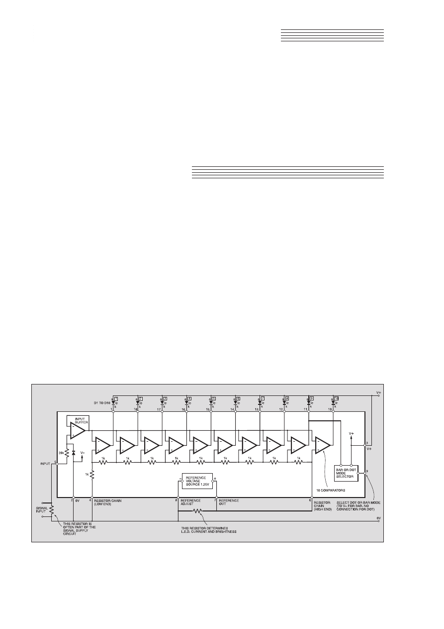
SSppeecciiaall CCoonnssttrruuccttiioonnaall FFeeaattuurree
W
HEN
something more robust, or
more easily read, than a moving
coil meter is needed, one of the
LM3914-6 family of dot- or bargraph dri-
vers and an l.e.d. display will usually pro-
vide a solution.
Manufactured by National Semi-
conductors, this “family’’ of chips (three)
is extremely versatile. A single resistor and
ten l.e.d.s are the only extra components
required to produce a basic voltmeter or
signal-strength meter. Two or three more
resistors enable sensitivity to be adjusted,
or the range expanded until a small, but
critical, voltage change fills the entire
display.
INTERNAL STRUCTURE
The internal arrangement of the
LM3914 i.c. is shown in Fig.1.
The Comparators
At the heart of the device is a chain of ten
resistors which set the bias on ten compara-
tors so that l.e.d.s are switched on sequential-
ly as the input voltage rises. The LM3914, 5
and 6 are identical apart from the values of
the resistors in the voltage divider chain.
In the LM3914 the resistors have equal
values to produce the linear response
required for voltmeter applications. The
resistors in the LM3915 are scaled loga-
rithmically, and span 0dB to 30dB in ten
3dB steps, making this version suitable for
signal-strength and power meters. The
resistors in the LM3916 are related in a
semi-log fashion to simulate a VU meter.
Input Buffer
A high input impedance buffer stage
minimises loading on the circuit under
measurement. The stage is protected against
reverse polarity inputs by a shunt connected
diode, and up to 35V can be applied to input
pin 5 before any damage occurs.
This can be increased to 100V by plac-
ing a 39 kilohms resistor in series with the
input. Pin 5 must be connected to the 0V
rail via a resistor of not more than 100
kilohms ohms or l.e.d. 10 will lock on.
Reference Voltage
Although the ends of the resistor chain
can be connected to external reference
voltages, it is generally more convenient to
use the reference produced within the i.c.
Typically 1·25V (it can vary from 1·2V to
1·34V), it is brought out at pins 7 and 8.
The voltage at pin 7 (Reference Out) can
be increased to a maximum of 12V by con-
necting pin 8 (Ref. Adj.) to the 0V rail via
USING THE
LM3914-6 L.E.D.
BARGRAPH DRIVERS
Getting to grips with this versatile family of l.e.d. and bargraph
driver i.c.s couldn’t be easier. We include practical circuits and
a multi-purpose p.c.b. set that will turn ten l.e.d.s into a robust,
easily read, voltage display – and more!
Everyday Practical Electronics, February 2001
121
RAYMOND HAIGH
Fig.1. Block schematic diagram for the LM3914 l.e.d. bargraph driver showing the simplest external circuit. The LM3915 and
LM3916 are identical except for the values of the internal resistors which determine the switching of the comparators.
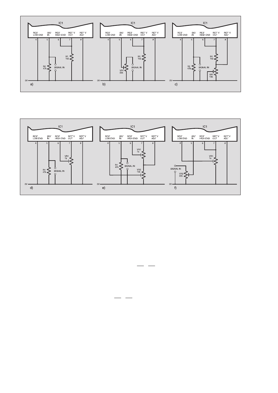
a resistor. The ability to increase the inter-
nal reference in this way makes it easier to
set sensitivity over wider limits.
Bar or Dot Mode
A Bar or Dot mode selector is brought
out to pin 9. Leaving pin 9 unconnected
results in a dot display. Connecting pin 9 to
pin 3 produces a bargraph.
Supply Voltage and Current
The supply voltage to the chip can be as
low as 3V. It must, however, always be at
least 1·5V more than the reference voltage
applied to the “high’’ end of the internal
resistor chain. The absolute maximum sup-
ply voltage is 25V.
Standby current (all l.e.d.s off) varies
from around 3mA with a 5V supply to
10mA with a 20V power supply rail.
FIXING L.E.D.
CURRENT
Current flow through each individual
l.e.d. is ten times the current drain on the
internal reference. L.E.D. current can,
therefore, be programmed by a resistor
connected between pin 7 and pin 8 (see
Fig.1).
If the internal resistor chain is connected
across the reference source (it usually is)
the current through it must be added to the
current through the programming resistor.
When the LM3914 is used, the total resis-
tance of the chain is nominally 10 kilohms,
and l.e.d. current can be calculated from
the following formula:
L.E.D. current = 10
(
1·25 + 1·25
)
R
10k
when R is the value of the programming
resistor.
With a 1·2k programming resistor, indi-
vidual l.e.d. current is:
10
(
1·25 + 1·25
)
= 11·6mA
1200 10000
and the current in bargraph mode with all
l.e.d.s on would, of course, rise to 116mA.
The reference voltage and value of the
resistor chain can vary significantly
between samples of the i.c., and some
departure from the calculated current can
be expected. The resistor chains in the
LM3915 and LM3916 exceed 20 kilohms,
and their contribution to l.e.d. current can
usually be ignored.
SENSITIVITY AND
RANGE
The input voltage required to turn l.e.d.
10 (D10) on is equal to the reference volt-
age applied to the “high’’ end of the resis-
tor chain. Similarly, the input required to
turn l.e.d. one (D1) on is determined by the
voltage applied to the “low’’ end.
There are limitations. The “low’’ end of
the chain cannot be taken below the 0V
rail, and the potential on the “high’’ end
cannot exceed 1·5V below the power sup-
ply voltage. The internal reference can be
set no higher than 12V.
The various ways in which the sensitivi-
ty and measurement range can be adjusted
are illustrated in Fig.2a to Fig.2f. A brief
description of the various methods of
adjusting the input sensitivity follows:
Basic Sensitivity (Fig.2a)
Connecting pin 6 to pin 7 applies the
internal reference to the “high’’ end of the
resistor chain and the input voltage
required to turn l.e.d. 10 (D10) on is, there-
fore, fixed at 1·25V.
The “low’’ end of the chain, pin 4, is
connected to the negative terminal of the
122
Everyday Practical Electronics, February 2001
Fig.2a. Basic Sensitivity. Connecting the internal resistor chain directly across the 1·25V reference gives an input sensitivity, to
l.e.d. D10 on, of 1·25V. Fig.2b. Reducing Sensitivity (Method One). Connecting the input to pin 5 via a preset potentiometer is
the simplest way of reducing sensitivity. Fig.2c. Reducing Sensitivity (Method Two). Grounding pin 8 (Reference Adjust) via
potentiometer VR1 increases the voltage across the internal resistor chain. This increases the input voltage required to turn
l.e.d. D10 on. With a value of 10k for VR1, the sensitivity can be varied from 1·25V to more than 10V.
Fig.2d. Increasing Sensitivity. By connecting the “high’’ end of the internal resistor chain to the slider of potentiometer VR1, the
input voltage to turn l.e.d. D10 on can be reduced to 0·1V or less. Fig.2e. Expanded Range (Method One). Connecting the
ends of the internal resistor chain to the sliders of potentiometers VR1 and VR2 enables l.e.d. D1 and l.e.d. D10 “on’’ voltages
to be adjusted. In this way a small, but critical, voltage change can be expanded to fill the entire display. Fig.2f. Expanded
Range (Method Two). Connecting the “low’’ end of the internal resistor chain to the slider of VR1 enables range minimum (the
input voltage required to turn l.e.d. D1 on) to be set between one tenth of range maximum and close to range maximum. Range
maximum (the input voltage required to turn l.e.d. D10 on) is set by potentiometer VR2.

reference, pin 8, via the 0V rail. The input
voltage required to turn l.e.d. one (D1) on
is, therefore, one-tenth of 1·25V or 125mV,
and each increment of 125mV turns
another l.e.d. on.
L.E.D. current is programmed by resis-
tor R1 which is, in effect, connected across
the internal reference source.
Reducing Sensitivity (Fig.2b):
Method One
Applying the input signal via poten-
tiometer, VR1, enables the voltage for l.e.d.
10 on to be set at any level above the 1·25V
internal reference. Inputs much in excess
of 50V should be connected via a fixed
resistor of suitable value to avoid the power
rating of the potentiometer being exceeded.
Reducing Sensitivity (Fig.2c):
Method Two
The reference voltage at pin 7 can be
increased by connecting pin 8 to the 0V rail
via a resistor. In Fig.2c, the current flowing
in resistor R1 is grounded via preset poten-
tiometer VR1 (wired as a variable resistor),
thereby increasing the voltage at pin 7 and
pin 8. Applying this increased reference
voltage to the “high’’ end of the internal
resistor chain increases the voltage
required to turn l.e.d. 10 on.
The formula relating resistor values to
reference voltage is:
Reference voltage =
1·25
(
1 +
VR1
)
+ VR1 ×
80
R1
10
6
(The above formula allows for an 80
mA
current flowing out of pin 8 to ground via
VR1.)
By making the resistor between pin 8
and ground (0V) a 10 kilohms preset
potentiometer, the reference voltage can be
varied from 1·25V (VR1 at zero resistance)
to 12V (VR1 near maximum).
Increasing Sensitivity (Fig.2d)
The basic sensitivity of 1·25V can be
low for some applications. If preset VR1
is connected across the reference voltage
and its slider (moving contact) taken to
the “high’’ end (pin 6) of the internal
resistor chain, the input to turn l.e.d. 10
on can be varied from 1·25V down to
100mV.
Expanding the Range (Fig.2e):
Method One
Sometimes it is desirable to expand a
small, but critical, voltage range to fill the
entire display. Battery condition checkers
often rely on circuits of this kind.
Range maximum is set just above the
fully charged or “fresh’’ voltage, and
range minimum is set a little below the
voltage at which the working of the
equipment would be impaired. Different
coloured l.e.d.s representing “good’’,
“acceptable’’ and “dubious’’ ensure an
easily read display, and a resistor to sim-
ulate the normal load should be wired
across the cell under test.
In Fig.2e, preset potentiometer VR2
increases the reference voltage at pin 7.
The “low’’ end of the internal resistor chain
(pin 4) is connected to its slider enabling
range minimum to be shifted over wide
limits.
Adjustment of range maximum is facili-
tated by connecting the “high’’ end of the
chain (pin 6) to the slider of VR1.
The resistance of VR2 should chosen to
increase the voltage on pin 7 to a level just
above range maximum. If necessary, con-
nect fixed and variable resistors in series to
produce the desired value.
Expanding the Range (Fig.2f):
Method Two
A more versatile method of expanding
the range is shown in Fig.2f, where the cir-
cuit is configured for a basic sensitivity of
1·25V. Connecting the slider of preset VR1
to the “low’’ end of the resistor chain
enables range minimum to be set anywhere
between one-tenth of range maximum and
close to range maximum.
Range maximum is set at any level
above 1·25V by potentiometer VR2.
ACCURACY
Accuracy is partially dependant on the
switching precision of the comparators,
and their performance improves as the
voltage across the internal chain of resis-
tors approaches its maximum value. For
this reason, the sensitivity adjusting cir-
cuits given in Fig.2c and 2e are to be pre-
ferred when accuracy is paramount. The
circuits in 2b and 2f will, however, func-
tion with power supply voltages down to
3V.
Temperature variations, over a 0°C to
70°C range, have a negligible effect, espe-
cially if the voltage across the internal
resistor chain is kept high.
When considering the question of accu-
racy, it should always be remembered that
this method of displaying voltage lacks the
precision of a digital or large moving-coil
meter. The l.e.d.s are switched in a series of
one-tenth steps and, to avoid display ambi-
guity, one l.e.d. fades out whilst the next is
switching on.
Unless, therefore, there is considerable
expansion, the display inevitably repre-
sents an approximation of the voltage
being measured.
DISSIPATION
The manufacturers of the devices quote
an absolute maximum power dissipation of
1365mW, and this figure has to be de-rated
if the ambient temperature is higher than
normal. When the display is configured in
the bar mode, it is prudent, therefore, to
check that total dissipation does not exceed,
say, 600mW when all l.e.d.s are on.
Voltage drop across the l.e.d.s is deter-
mined by colour. It is near enough 2V for
red, yellow and green l.e.d.s, and around
3·6V for white and blue.
To calculate dissipation, deduct the
l.e.d. voltage drop from the supply volt-
age to give the voltage across the i.c., and
multiply this by the total l.e.d. current
plus, say, 10mA for device standing
current.
With red l.e.d.s working at 10mA, and
with a supply voltage of 12V:
Voltage across i.c. = 12 – 2 = 10V.
Maximum current = 10 + (10 × 10) = 110mA
Maximum dissipation = 10 × 110 = 1100mW,
which is too high for safety.
Adopting dot instead of bar mode will
bring dissipation within safe limits, and
l.e.d. current can be reduced by increasing
the value of the resistor between pin 7 and
pin 8. However, for many applications
using standard l.e.d.s, a current of 10mA is
required to produce a bright enough
display.
Dissipation can, of course, be reduced
by reducing the supply voltage to the i.c.,
but it must always be 1·5V or more above
the voltage applied to the internal resistor
chain. When the supply to the i.c. has to be
high for this reason, dissipation can be
reduced by using a separate power supply
of 3V or 5V for the l.e.d.s.
If separate supplies are inconvenient,
dissipation can be kept within safe limits
by placing a 470 ohm resistor in series with
each l.e.d.. The manufacturers suggest a
single resistor placed in series with the
l.e.d.’s common anode lead (the l.e.d. end
of this resistor should be bypassed to the
0V rail by a 10
mF electrolytic capacitor).
With this method there may be a percepti-
ble reduction in brightness as the bargraph
extends.
Everyday Practical Electronics, February 2001
123
Voltmeter with adjustable input sensi-
tivity (1·25V to 10V) circuit board. See
Fig.2c for circuit and Fig.10a for p.c.b.
details.
Bargraph display with “warning’’
flasher. Sensitivity adjustable from
1·25V upwards. See Fig.4 for circuit
and Fig.10c for board details.
Remote Relay Driver circuit board. See
Fig.7 for circuit diagram and Fig.10f for
board details. It is possible to control up to
10 relays, using the control board of Fig.9.
Signal-Strength Meter (dot-mode) with
amplified and rectified input. See Fig.2a
for sensivity fixing, Fig.5 for input circuit
and Fig.10e for p.c.b. details.
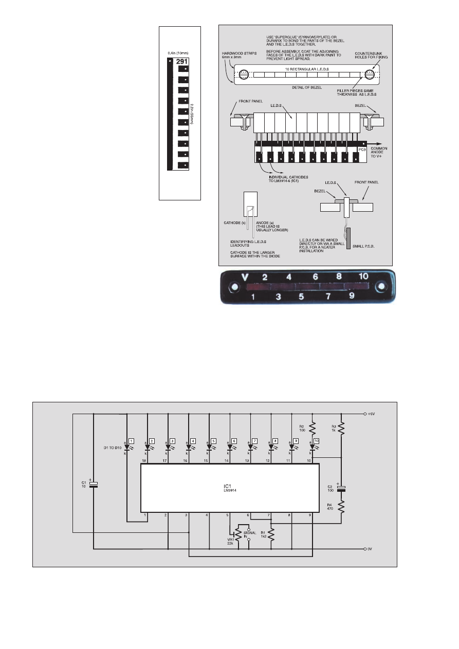
124
Everyday Practical Electronics, February 2001
FLASHING DISPLAYS
How the entire display can be made to
flash when a critical voltage level has been
reached is shown in Fig.4. Bargraph mode
(pin 9 to pin 3) must be adopted with this
arrangement.
The display can be made to start flash-
ing from l.e.d. 2 onwards. Simply connect
resistor R2 in series with the anode (a), and
take the junction of resistor R3 and capac-
itor C2 to the cathode (k), of the l.e.d.
where flashing is to start.
SIGNAL STRENGTH
METERS
Bargraph drivers are commonly used
for signal strength and power meters. The
LM3915, with its logarithmic response, is
the natural choice for applications of this
kind.
The simplest system involves the direct
connection of the signal to pin 5.
Remember to include a blocking capacitor
if d.c. is present: a 220nF ceramic or poly-
styrene component is suitable.
STABILITY
The circuit may become unstable if the
l.e.d. connecting leads are longer than
150mm. A 10
mF electrolytic capacitor
connected across the power supply rails,
and mounted reasonably close to pins 2
and 3, avoids this possibility.
Instability can also arise if the internal
resistor chain is connected to independent
reference voltages of high impedance.
Bypassing pin 6 to ground via a 100nF
capacitor will eliminate any problems.
L.E.D.S
The efficiency of l.e.d.s (light emitting
diodes) in terms of light output for a given
current varies considerably. The so-called
“high brightness’’ l.e.d.s certainly produce
a vivid display, but this is usually achieved
by adopting current levels of 20mA or
more.
If current economy is important, either
to contain dissipation or to extend battery
life, low current l.e.d.s, which are very
luminous at 2mA, represent an ideal solu-
tion. The 3mm types seem brighter than
their 5mm counterparts, no doubt because
the light source is not obscured by so much
plastic.
By using low current l.e.d.s in the dot
mode with a 3V supply, and increasing
the l.e.d. current programming resistor
to 10 kilohms (R1 in Fig.2a), a very
economical voltage display can be
produced.
BARGRAPH DISPLAYS
Rectangular l.e.d.s are more appropriate
for bar graphs, and separate diodes can be
combined into a ten l.e.d. display. A
method of doing this is illustrated in Fig.3.
The provision of a bezel avoids the dif-
ficulty of cutting a neat rectangular slot in
the instrument case, and l.e.d.s of different
colour can be combined. The meeting
faces of the l.e.d.s must be coated with
dark paint before being glued together, or
light spread will be a problem.
Ten segment displays can be purchased
for little more than the cost of separate
l.e.d.s. This does, however, deny the con-
structor the opportunity to mix l.e.d.s of
different colours.
Ω
Ω
µ
µ
Fig.4. Circuit diagram for the Bargraph display, with alarm flasher. When D10 is activated it begins to flash.
Fig.3b.
Full-size
L.E.D. Display foil
master.
Fig.3a. Assembly
details for making
the l.e.d. bargraph.
“ H o m e b r e w e d ”
bargraph display
using separate
l.e.d.s.
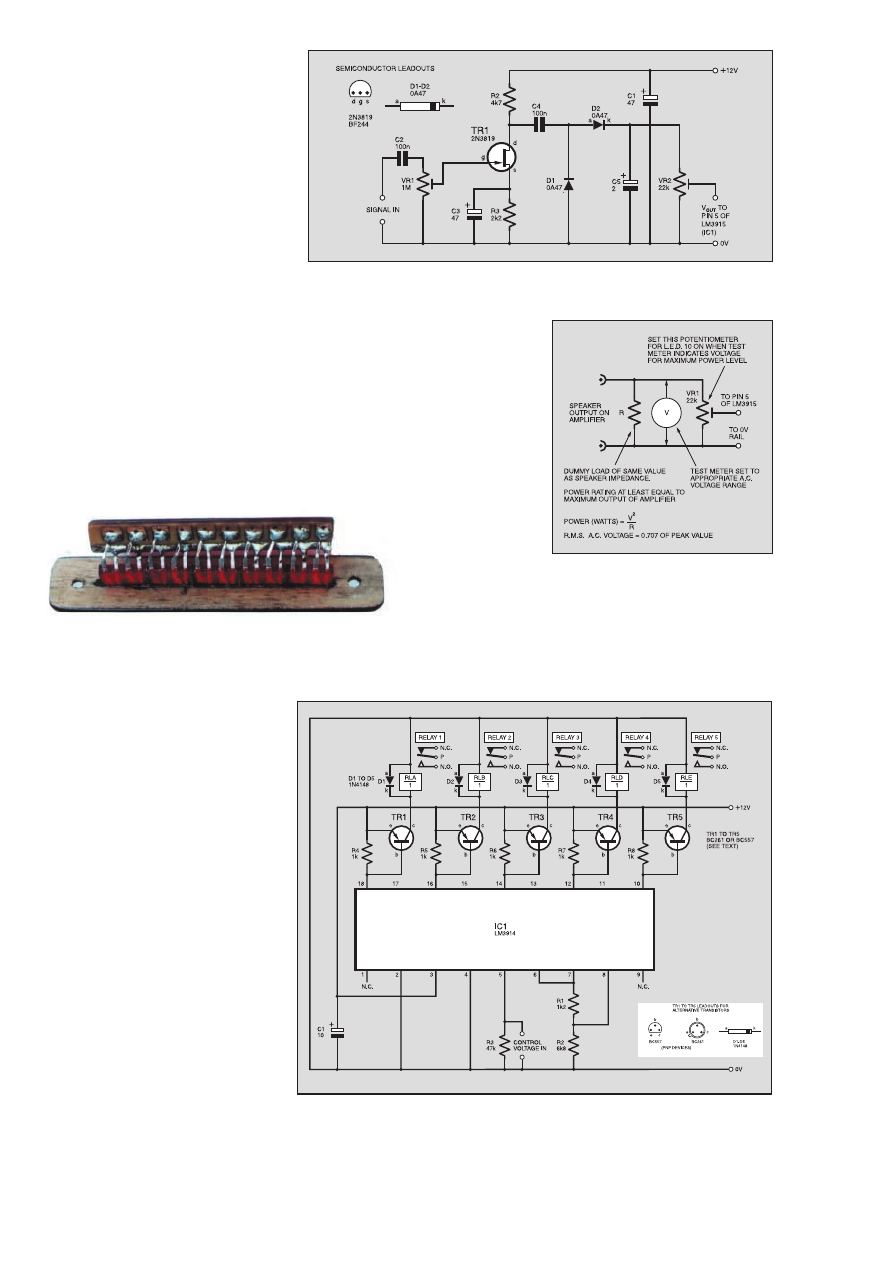
The manufacturers recommend dot
mode and a 30mA l.e.d. current when this
method is adopted. If, however, the display
seems patchy at high signal levels, try the
bar mode and a lower l.e.d. current.
When a sensitivity greater than the basic
1·25V is required, use the circuit given in
Fig.2d.
RECTIFIERS
Better results can be obtained by rectify-
ing the signal and applying d.c. to the
bargraph driver. A suitable circuit is given
in Fig.5.
Transistor TR1 amplifies the signal to
ensure that diodes D1 and D2 are working
in their conductive region. The diodes are
arranged in a voltage doubling circuit, and
preset potentiometer VR1 should be set
just short of signal clipping in TR1 to
ensure that they are driven hard.
Potentiometer VR2 is then set to deliver
the required input to the i.c.
The high input impedance of the field-
effect transistor, TR1, minimises loading
on the signal circuit, and reservoir capaci-
tor C5 sharpens the l.e.d. display. The
amplifier and rectifier circuit can be
teamed with the basic i.c. arrangement
illustrated in Fig.2a, and a 12V power sup-
ply is required.
If the bargraph mode is chosen, take one
or other of the measures outlined earlier to
ensure that dissipation is not excessive.
The stabilising capacitor across the power
supply, C1, should be increased to 47
mF
when this circuit is used.
POWER METERS
Signal strength meters can be adjusted
to indicate power levels. The load is known
(the speaker impedance quoted by the
manufacturers), and the power delivered is,
of course, proportional to the voltage
developed across it.
How a dummy load, test meter and the
bargraph driver are connected during the
setting up process is shown in the circuit of
Fig.6. Simply inject a signal into the
amplifier, increasing it until the test meter
indicates that the maximum power level
has been reached, then set preset VR1 to
light l.e.d. 10.
The formula relating power to voltage
and load impedance is also given in Fig.6:
e.g., with a 4 ohm speaker, 10 watts is
being supplied when 6·3V is developed
across the dummy load, 50 watts when the
voltage is 14V, and 100 watts when the
voltage is 20V.
The setting up signal should be below
1kHz because the accuracy of most test
meters reduces at frequencies much higher
than this. Provided the response of the
amplifier is wide enough, 50Hz from a low
voltage transformer can be applied if a sig-
nal generator is not available.
Test meters indicate the r.m.s. values of
a.c. voltages, and the power meter will,
therefore, display r.m.s. power levels. If
peak power is to be displayed, set VR1 so
that l.e.d. 10 (D10) lights when the voltage
reading on the test meter is 0·707 times the
value indicated by the formula in Fig.6.
REMOTE RELAY
DRIVER
If switching transistors and relays are
substituted for the l.e.d.s, the LM3914 can
be used to control up to ten functions via a
two-wire link.
The circuit diagram for a Relay Driver
set-up using the
LM3914 is given in
Fig.7. When one of
the comparators draws
current,
the voltage
developed across base/
emitter resistor, R4 to
R8, makes the relevant
transistor collector (c)
conduct and the asssoci-
ated relay coil is
energised. Diodes D1 to D5 shunt the
high voltage developed across the relay
coil when the transistor turns off.
The combination of resistors R1 and R2
fixes the voltage across the resistor chain at
9V. This ensures a good difference
between trigger levels and adjustment of
the control voltages is less critical. Only
Everyday Practical Electronics, February 2001
125
µ
µ
µ
Fig.5. Amplifier and rectifier stages for the Signal Strength Meter. R1 is the l.e.d.
brightness resistor, not shown here – see Fig.2a. VR2 acts as the input (pin 5)
grounding resistor (R2 in Fig.2a).
Fig.6. Setting up bargraph drivers to
display peak r.m.s. power.
µ
Fig.7. Circuit diagram for using the LM3914 as a relay driver. Remote control of up
to ten relays, via two wires, is possible.
k
a
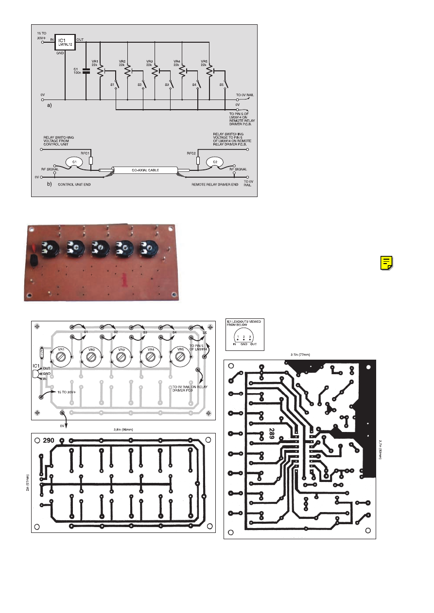
five relay circuits are shown,
but all ten outputs from the
i.c. can be used if desired.
A relay control board cir-
cuit diagram is given in
Fig.8a. Control voltages are
set by potentiometers VR1
to VR5 and selected by
switches S1 to S5. Voltage
regulator IC1 ensures that
the correct voltage levels are
maintained. Broad band r.f.
noise developed by the i.c. is
bypassed by capacitor C1.
This avoids problems when the control
voltages are carried by an r.f. signal cable
in the manner illustrated in Fig.8b. Here,
r.f. chokes, RFC1 and RFC2, isolate the
signals from the control circuitry, and
blocking capacitors C1 and C2 prevent the
flow of d.c. into the signal circuits.
Select the inductance of the chokes to suit
the signal frequencies: e.g., 4·7mH for low
and medium frequencies, and 1mH for
medium and high frequencies. The capaci-
tors can be 100nF ceramic type.
Alternatively, three-core cable can be
used: one wire supplying low voltage
power for the LM3914 and, say, drive
motors, another the control voltages, and
the third a common 0V rail.
The only disadvantage to the system is
that only one relay can be activated at any
one time. However, with up to ten circuits
available, this is no great drawback.
CIRCUIT ASSEMBLY
The full-size foil and component sides of a
p.c.b. for the Relay Driver Control Board are
shown in Fig.9. Although five circuits are
shown, provision is made on both p.c.b.s for
all ten to be installed should this be required
The components for the various circuits
are best assembled on a small printed cir-
cuit board (p.c.b.). The full-size, copper
foil side of a multi-purpose board, which
can accommodate all of the circuits dis-
cussed, is shown in Fig.11. The various
topside component layouts are illustrated
in Fig.10a to Fig.10f, also see the photo-
graphs. The board (one only) is part of a set
which is available from the EPE PCB
Service, codes 289/290/291.
It is a good idea to use a holder for the
LM3914/6, and solder pins, inserted at the
lead out points, ease the task of off-board
wiring. Use a small crocodile clip as a
heat-shunt when soldering the f.e.t. (TR1)
and germanium diodes (D1, D2) for the
“rectified’’ version of the Signal Strength
Meter in Fig.5. Remember to include the
wire links, and always check the orienta-
tion of electrolytics and semiconductors
before applying power to the board.
$
Fig.8. Control Unit and applying switching voltages via an r.f. signal cable. (a) circuit
diagram and (b) cable interlink details.
Fig.9. Relay Control p.c.b. component layout and foil master.
126
Everyday Practical Electronics, February 2001
Fig.11. Full-size Multi-purpose L.E.D. Driver foil master.
Relay Control board (for 5 relays).
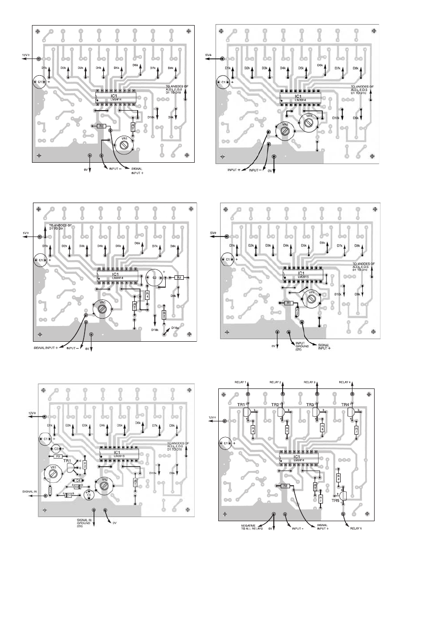
Fig.10e. Component layout for Signal-Strength Meter
(dot-mode), with amplified and rectified input. See Fig.5
for input circuit. See Fig.2a for i.c. sensitivity fixing circuit.
Fig.10c. Component layout for Bargraph display, with alarm
flasher. Sensitivity adjustable from 1·25V upwards. See
Fig.4 for circuit.
Fig.10a. Component layout for Voltmeter with adjustable
input sensitivity (1·25V-10V). See Fig.2c for input circuit.
C1 is a 10
mF capacitor connected across the supply rails.
Fig.10b. Component layout for expanded range dot mode
voltmeter. See Fig.2f for circuit.
Fig.10d. Component layout for basic bar-mode Signal-
Strength Meter. Input sensitivity adjustable over a 100mV
to 1·25V range. See Fig.2d for circuit. C2 is a 220nF d.c.
blocking capacitor at the input.
Fig.10f. Component layout for Remote Relay Driver. See
Fig.7 for circuit diagram. Up to ten relays can be
controlled.
Everyday Practical Electronics, February 2001
127
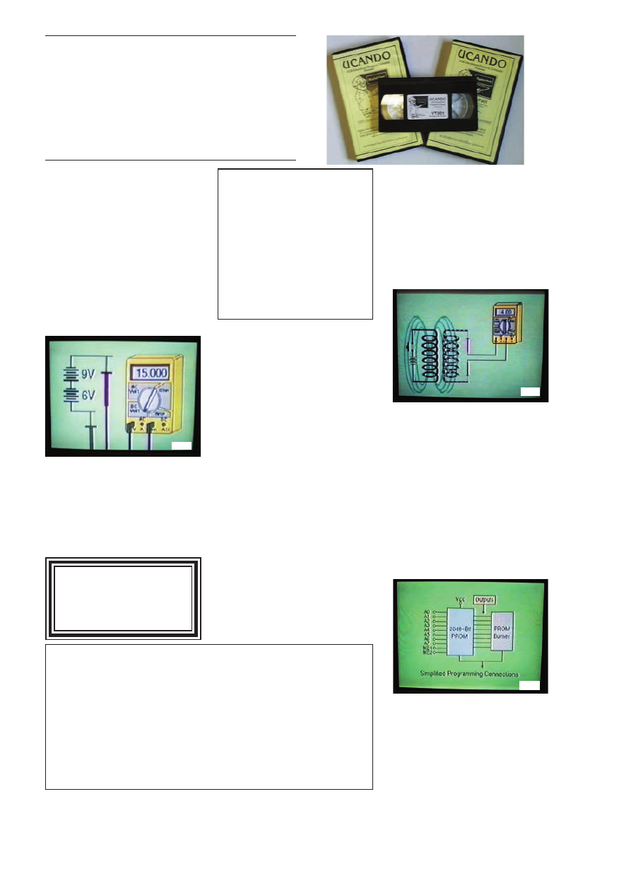
V
VC
CR
R M
MA
AIIN
NT
TE
EN
NA
AN
NC
CE
E
V
VT
T1
10
02
2 84 minutes: Introduction to VCR
Repair. Warning, not for the beginner.
Through the use of block diagrams this
video will take you through the various
circuits found in the NTSC VHS system.
You will follow the signal from the input to
the audio/video heads then from the
heads back to the output.
O
Orrd
de
err C
Co
od
de
e V
VT
T1
10
02
2
V
VT
T1
10
03
3 35 minutes: A step-by-step easy to
follow procedure for professionally clean-
ing the tape path and replacing many of
the belts in most VHS VCR's. The viewer
will also become familiar with the various
parts found in the tape path.
O
Orrd
de
err C
Co
od
de
e V
VT
T1
10
03
3
O
OR
RD
DE
ER
RIIN
NG
G:: P
Prriic
ce
e iin
nc
cllu
ud
de
ess p
po
osstta
ag
ge
e tto
o a
an
ny
yw
wh
he
erre
e iin
n tth
he
e w
wo
orrlld
d..
O
OV
VE
ER
RS
SE
EA
AS
S O
OR
RD
DE
ER
RS
S:: We use the VAT portion of the price to pay for
airmail postage
and packing, wherever you live in the world. Just send £34.95 per tape. All payments
in £ sterling only (send cheque or money order drawn on a UK bank). Make cheques
payable to Direct Book Service.
V
Viissa
a,, M
Ma
asstte
errc
ca
arrd
d and S
Sw
wiittc
ch
h orders accepted – please give card number, card expiry
date and Switch Issue No.
Orders are normally sent within seven days but please allow a maximum of 28 days,
longer for overseas orders.
S
Se
en
nd
d y
yo
ou
urr o
orrd
de
err tto
o:: D
Diirre
ec
ctt B
Bo
oo
ok
k S
Se
errv
viic
ce
e,, Allen House, East Borough, Wimborne,
Dorset BH21 1PF
Direct Book Service is a division of Wimborne Publishing Ltd., Publishers of
EPE
T
Te
ell:: 0
01
12
20
02
2 8
88
81
17
74
49
9.. F
Fa
ax
x:: 0
01
12
20
02
2 8
84
41
16
69
92
2
E
E--m
ma
aiill:: dbs@epemag.wimborne.co.uk
Each video uses a mixture of animated current
flow in circuits plus text, plus cartoon instruc-
tion etc., and a very full commentary to get the
points across. The tapes are imported by us and
originate from VCR Educational Products Co,
an American supplier. We are the worldwide
distributors of the PAL and SECAM versions of
these tapes. (All videos are to the UK PAL stan-
dard on VHS tapes unless you specifically
request SECAM versions.)
VIDEOS ON
ELECTRONICS
A range of videos selected by
EPE and designed to provide instruc-
tion on electronics theory. Each video gives a sound introduction
and grounding in a specialised area of the subject. The tapes make
learning both easier and more enjoyable than pure textbook or
magazine study. They have proved particularly useful in schools,
colleges, training departments and electronics clubs as well as to
general hobbyists and those following distance learning courses etc
B
BA
AS
SIIC
CS
S
V
VT
T2
20
01
1 tto
o V
VT
T2
20
06
6 iiss a
a b
ba
assiic
c e
elle
ec
cttrro
on
niic
css c
co
ou
urrsse
e
a
an
nd
d iiss d
de
essiig
gn
ne
ed
d tto
o b
be
e u
usse
ed
d a
ass a
a c
co
om
mp
plle
ette
e
sse
erriie
ess,, iiff rre
eq
qu
uiirre
ed
d..
V
VT
T2
20
01
1 54 minutes. Part One; D
D..C
C.. C
Ciirrc
cu
uiittss..
This video is an absolute must for the begin-
ner. Series circuits, parallel circuits, Ohms
law, how to use the digital multimeter and
much more.
O
Orrd
de
err C
Co
od
de
e V
VT
T2
20
01
1
V
VT
T2
20
02
2 62 minutes. Part Two; A
A..C
C.. C
Ciirrc
cu
uiittss..
This is your next step in understanding the
basics of electronics. You will learn about how
coils, transformers, capacitors, etc are used in
common circuits.
O
Orrd
de
err C
Co
od
de
e V
VT
T2
20
02
2
V
VT
T2
20
03
3 57 minutes. Part Three; S
Se
em
miic
co
on
n--
d
du
uc
ctto
orrss.. Gives you an exciting look into the
world of semiconductors. With basic semicon-
ductor theory. Plus 15 different semiconduc-
tor devices explained.
O
Orrd
de
err C
Co
od
de
e V
VT
T2
20
03
3
V
VT
T2
20
04
4 56 minutes. Part Four; P
Po
ow
we
err
S
Su
up
pp
plliie
ess.. Guides you step-by-step through
different sections of a power supply.
O
Orrd
de
err C
Co
od
de
e V
VT
T2
20
04
4
V
VT
T2
20
05
5 57 minutes. Part Five; A
Am
mp
plliiffiie
errss..
Shows you how amplifiers work as you have
never seen them before. Class A, class B,
class C, op.amps. etc.
O
Orrd
de
err C
Co
od
de
e V
VT
T2
20
05
5
V
VT
T2
20
06
6 54 minutes. Part Six; O
Ossc
ciilllla
atto
orrss..
Oscillators are found in both linear and digi-
tal circuits. Gives a good basic background in
oscillator circuits.
O
Orrd
de
err C
Co
od
de
e V
VT
T2
20
06
6
D
DIIG
GIIT
TA
AL
L
N
No
ow
w ffo
orr tth
he
e d
diig
giitta
all sse
erriie
ess o
off ssiix
x v
viid
de
eo
oss.. T
Th
hiiss
sse
erriie
ess iiss d
de
essiig
gn
ne
ed
d tto
o p
prro
ov
viid
de
e a
a g
go
oo
od
d g
grro
ou
un
nd
d--
iin
ng
g iin
n d
diig
giitta
all a
an
nd
d c
co
om
mp
pu
utte
err tte
ec
ch
hn
no
ollo
og
gy
y..
V
VT
T3
30
01
1 54 minutes. Digital One; G
Ga
atte
ess begins
with the basics as you learn about seven of
the most common gates which are used in
almost every digital circuit, plus Binary
notation.
O
Orrd
de
err C
Co
od
de
e V
VT
T3
30
01
1
V
VT
T3
30
02
2 55 minutes. Digital Two; F
Flliip
p F
Fllo
op
pss
will further enhance your knowledge of digital
basics. You will learn about Octal and
Hexadecimal notation groups, flip-flops,
counters, etc.
O
Orrd
de
err C
Co
od
de
e V
VT
T3
30
02
2
V
VT
T3
30
03
3 54 minutes. Digital Three; R
Re
eg
giisstte
errss
a
an
nd
d D
Diissp
plla
ay
yss is your next step in obtaining a
solid understanding of the basic circuits
found in today’s digital designs. Gets into
multiplexers, registers, display devices, etc.
O
Orrd
de
err C
Co
od
de
e V
VT
T3
30
03
3
V
VT
T3
30
04
4 59 minutes. Digital Four; D
DA
AC
C a
an
nd
d
A
AD
DC
C shows you how the computer is able to
communicate with the real world. You will
learn about digital-to-analogue and ana-
logue-to-digital converter circuits.
O
Orrd
de
err C
Co
od
de
e V
VT
T3
30
04
4
V
VT
T3
30
05
5 56 minutes. Digital Five; M
Me
em
mo
orry
y
D
De
ev
viic
ce
ess introduces you to the technology
used in many of today’s memory devices. You
will learn all about ROM devices and then
proceed into PROM, EPROM, EEPROM,
SRAM, DRAM, and MBM devices.
O
Orrd
de
err C
Co
od
de
e V
VT
T3
30
05
5
V
VT
T3
30
06
6 56 minutes. Digital Six; T
Th
he
e C
CP
PU
U
gives you a thorough understanding in the
basics of the central processing unit and the
input/output circuits used to make the system
work.
O
Orrd
de
err C
Co
od
de
e V
VT
T3
30
06
6
R
RA
AD
DIIO
O
V
VT
T4
40
01
1 61 minutes. A
A..M
M.. R
Ra
ad
diio
o T
Th
he
eo
orry
y.. The
most complete video ever produced on a.m.
radio. Begins with the basics of a.m. trans-
mission and proceeds to the five major stages
of a.m. reception. Learn how the signal is
detected, converted and reproduced. Also
covers the Motorola C-QUAM a.m. stereo
system.
O
Orrd
de
err C
Co
od
de
e V
VT
T4
40
01
1
V
VT
T4
40
02
2 58 minutes. F
F..M
M.. R
Ra
ad
diio
o P
Pa
arrtt 1
1.. F.M.
basics including the functional blocks of a
receiver. Plus r.f. amplifier, mixer oscillator,
i.f. amplifier, limiter and f.m. decoder stages
of a typical f.m. receiver. O
Orrd
de
err C
Co
od
de
e V
VT
T4
40
02
2
V
VT
T4
40
03
3 58 minutes. F
F..M
M.. R
Ra
ad
diio
o P
Pa
arrtt 2
2.. A con-
tinuation of f.m. technology from Part 1.
Begins with the detector stage output, pro-
ceeds to the 19kHz amplifier, frequency dou-
bler, stereo demultiplexer and audio amplifier
stages. Also covers RDS digital data encoding
and decoding.
O
Orrd
de
err C
Co
od
de
e V
VT
T4
40
03
3
M
MIIS
SC
CE
EL
LL
LA
AN
NE
EO
OU
US
S
V
VT
T5
50
01
1 58 minutes. F
Fiib
brre
e O
Op
pttiic
css.. From the
fundamentals of fibre optic technology
through cable manufacture to connectors,
transmitters and receivers.
O
Orrd
de
err C
Co
od
de
e V
VT
T5
50
01
1
V
VT
T5
50
02
2 57 minutes. L
La
asse
err T
Te
ec
ch
hn
no
ollo
og
gy
y A basic
introduction covering some of the common
uses of laser devices, plus the operation of the
Ruby Rod laser, HeNe laser, CO
2
gas laser
and semiconductor laser devices. Also covers
the basics of CD and bar code scanning.
O
Orrd
de
err C
Co
od
de
e V
VT
T5
50
02
2
£
£3
34
4..9
95
5
each
inc. VAT & postage
Order 8 or more get one extra FREE
Order 16 get two extra FREE
VT201
VT202
VT305
128
Everyday Practical Electronics, February 2001

Radio
Bygones
The leading magazine
for vintage radio
enthusiasts
W
HETHER
your interest is in domestic radio and TV or in amateur radio, in military, aeronautical or marine communications, in radar
and radio navigation, in instruments, in broadcasting, in audio and recording, or in professional radio systems fixed or mobile, R
ADIO
B
YGONES
is the magazine for you.
A
RTICLES
on restoration and repair, history, circuit techniques, personalities, reminiscences and just plain nostalgia youll find
them all. Plus features on museums and private collections and a full-colour photo-feature in every issue.
I
TS MOSTLY
about valves, of course, but solid-state whether of the coherer and spark-gap variety or early transistors also has a place.
F
ROM THE DAYS
of Maxwell, Hertz, Lodge and Marconi to what was the state-of-the-art just a few short years ago . . .
T
HERE IS ALSO
a selection of free readers' For Sale and Wanted advertisements in every issue.
Radio Bygones covers it all!
T
HE MAGAZINE
is published six times a year, and is only available by postal subscription. It is not available at newsagents.
T
O TAKE OUT
a subscription, or to order a sample copy, please contact:
R
ADIO
B
YGONES
, Allen House, East Borough, Wimborne, Dorset BH21 1PF.
Tel: 01202 881749. Fax 01202 841692. Web sites: www.radiobygones.co.uk www.radiobygones.com
Now Also
Available To
BUY ONLINE
www.radiobygones.com
Log on, pay by credit card
and download the magazine
to your PC
ONLY
$9.99
(US dollars)
FOR 6 ISSUES
A free issue is
available
Everyday Practical Electronics, February 2001
129
E
EP
PE
E T
TE
EA
AC
CH
H--IIN
N 2
20
00
00
0
Now on CD-ROM
NEW
The whole of the 12-part
Teach-In 2000 series by John
Becker (published in EPE Nov ’99 to Oct 2000) is now
available on CD-ROM. Plus the
Teach-In 2000 software
covering all aspects of the series and Alan Winstanley’s
Basic Soldering Guide (including illustrations and
Desoldering).
Teach-in 2000 covers all the basic principles of
electronics from Ohm’s Law to Displays, including Op.Amps,
Logic Gates etc. Each part has its own section on the inter-
active software where you can also change component val-
ues in the various on-screen demonstration circuits.
The series gives a hands-on approach to electronics with
numerous breadboarded circuits to try out, plus a simple
computer interface which allows a PC to be used as a basic
oscilloscope.
ONLY
£
£1
12
2..4
45
5
including VAT and p&p
NOTE: This mini CD-ROM is suitable for use on any PC with a
CD-ROM drive. It requires Adobe Acrobat Reader (available free
from the Internet – www.adobe.com/acrobat)
Order on-line from www.epemag.com or by Phone, Fax,
E-mail or Post
TEACH-IN 2000 CD-ROM ORDER FORM
Please send me .......................... (quantity) TEACH-IN 2000 CD-ROM
Price £12.45 (approx $20) each – includes postage to anywhere in the world.
Name . . . . . . . . . . . . . . . . . . . . . . . . . . . . . . . . . . . . . . . . . . . . . . . . . . . . .
Address . . . . . . . . . . . . . . . . . . . . . . . . . . . . . . . . . . . . . . . . . . . . . . . . . . .
. . . . . . . . . . . . . . . . . . . . . . . . . . . . . . . . . . . . . . . . . . . . . . . . . . . . . . . . . .
. . . . . . . . . . . . . . . . . . . . . . . . . . . . . . . . Post Code . . . . . . . . . . . . . . . .
$I enclose cheque/P.O./bank draft to the value of £ . . . . . . . . . . . . . . . . . .
$Please charge my Visa/Mastercard/Switch £ . . . . . . . . . . . . . . . . . . . . . .
Card No. . . . . . . . . . . . . . . . . . . . . . . . . . . . . . . . . . . . . . . . . . . . . . . . . . . .
Expiry Date . . . . . . . . . . . . . . . . . . . . . . Switch Issue No. . . . . . . . . . . . . .
Note: Minimum order for cards £5.
SEND TO: Everyday Practical Electronics, Allen House,
East Borough, Wimborne, Dorset BH21 1PF.
Tel: 01202 881749.
Fax: 01202 841692.
E-mail: orders@epemag.wimborne.co.uk
Payments must be by card or in £ Sterling – cheque or bank draft drawn on a UK bank.
Normally supplied within seven days of receipt of order.
Send a copy of this form, or order by letter if you do not wish to cut your issue.
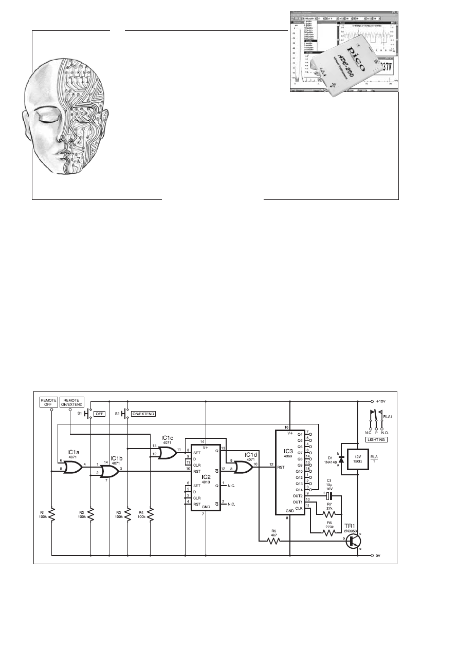
I
NGENUITY
UNLIMITED
Our regular round-up of readers' own circuits. We pay between
£10 and £50 for all material published, depending on length
and technical merit. We're looking for novel applications and
circuit designs, not simply mechanical, electrical or software
ideas. Ideas
must be the reader's own work
and must not
have been submitted for publication elsewhere. The
circuits shown have NOT been proven by us.
Ingenuity
Unlimited
is open to ALL abilities, but items for consideration in
this column should be typed or word-processed, with a brief
circuit description (between 100 and 500 words maximum) and
full circuit diagram showing all relevant component values.
Please draw all circuit schematics as clearly as possible.
Send your circuit ideas to: Alan Winstanley,
Ingenuity
Unlimited,
Wimborne Publishing Ltd., Allen House, East
Borough, Wimborne, Dorset BH21 1PF. (We do not accept
submissions for
IU
via E-mail.)
Your ideas could earn you some cash and a prize!
W
WIIN
N A
A P
PIIC
CO
O P
PC
C B
BA
AS
SE
ED
D
O
OS
SC
CIIL
LL
LO
OS
SC
CO
OP
PE
E
) 50MSPS Dual Channel Storage Oscilloscope
) 25MHz Spectrum Analyser
) Multimeter ) Frequency Meter
)Signal Generator
If you have a novel circuit idea which would be
of use to other readers then a Pico Technology
PC based oscilloscope could be yours.
Every six months, Pico Technology will be
awarding an ADC200-50 digital storage
oscilloscope for the best IU submission. In
addition, two single channel ADC-40s will be
presented to the runners-up.
130
Everyday Practical Electronics, February 2001
Garden Lighting Controller –
D
De
ella
ay
ye
ed
d A
Ac
cttiio
on
n
T
HE
circuit diagram shown in Fig.1 pro-
vides on/off pushbutton control for a
Garden Lighting System. In addition, there is
a 1½ hour timeout facility, as well as remote
control inputs at CMOS levels for external
control use if desired.
In these days of “PICS with everything’’
this is an example of good old-fashioned
logic. Assuming the lighting is off (IC2a at
reset), IC3 is held at reset via OR gate IC1d.
Pressing switch S2 sets IC2a via OR gate
IC1c, taking pin 13 high. This energises the
relay RLA which switches on the lighting,
via the relay contacts. Since pin 12 of 1C2a is
now low, IC3 is allowed to count.
Once the Q14 output, pin 3 of IC3, goes
high, flip-flop IC2a is reset via IC1a and
ICIb, removing the drive to transistor TR1.
Further presses of switch S2 during the tim-
ing interval will reset the timer via IC1c and
IC1d, so causing the time interval to start
again. Pressing switch S1 at any time resets
the flip-flop and the timer via IC1b, IC2, and
IC1d.
The 14-stage ripple counter IC3 contains a
multivibrator clock, the frequency of which is
set by Cl, R6, and R7 to around 1.5Hz. After
8,192 cycles Q14 output will go high (and
low again after a further 8,192 cycles, making
2
14
in all – ARW), which equates to a delay of
1·52 hours.
The contact arrangement of RLA1 is not
shown as it depends on your application. The
author used a d.p.d.t. relay, with its normally
open contacts in parallel, switching the mains
side of the lighting transformer. Ensure ade-
quate fusing is provided and that you take
care to ensure full isolation between the low
voltage and mains parts of the circuit, if
applicable.
Remote Control
The remote control inputs provided were
intended for a system based on the Holtek
HT12 series of encoders/decoders. Overall
the system will then provide multipoint con-
trol, with the knowledge that if the lights are
left on, they will turn off automatically, pre-
serving the life of the lamps in the outside
fittings. Note that the HT12D decoder chips
have latching outputs and that if used in con-
junction with this circuit, steps must be
taken to ensure a momentary pulse is
supplied.
As a final tip, I originally had a Hozelock
24V a.c. lighting set. Most systems are now
12V, so in order to use the original trans-
former I placed a 1N4001 diode in series with
12V 4W lamps. By arranging an equal num-
ber of fittings to operate on each half cycle
(reversing the orientation of the diode), the
transformer sees a balanced load and the 12V
lamps will not burn out.
David Geary,
Blackheath,
London.
Fig.1. Circuit diagram for a Garden Lighting Controller, with timeout and remote control features.

S
SU
UR
RV
VE
EIIL
LL
LA
AN
NC
CE
E
SEND 2 x 1st CLASS STAMPS FOR OUR 2000 KIT CATALOGUE
CONTAINING FULL DETAILS OF THESE AND OTHER KITS.
A BUILD-UP SERVICE IS AVAILABLE ON ALL OF OUR KITS, DETAILS IN
CATALOGUE. VISIT OUR WEBSITE: www.suma-designs.co.uk
Please note: Some of our part numbers are being unscrupulously used by
other companies selling kits eg. MTX, VXT. DO NOT BE MISLEAD! These are
NOT GENUINE SUMA KITS which are only available direct from us or our
appointed distributors.
If you wish to collect kits direct from our office
PLEASE TELEPHONE
SUMA
DESIGNS
Dept. EE, The Workshops, 95 Main Road,
Baxterley, Warwickshire, CV9 2LE, U.K.
Website: www.suma-designs.co.uk
TEL/FAX: 01827 714476
(24 HOUR ORDERLINE)
email: sales@suma-designs.co.uk
Electronic Surveillance Equipment Kits from the UK’s No.1 Supplier
SUMA DESIGNS has been supplying professional quality electronic surveillance equipment kits for over 20 years. Whether your
requirement is hobbyist, amateur or professional you can be sure that you are buying from a company that knows the business.
We ONLY sell surveillance products, no alarms, disco lights or computer bits. All of our kits are designed for self assembly and
are well tried, tested and proven. All kits are supplied complete with top grade components, fibreglass PCB, full instructions,
circuit diagrams and assembly details. Unless otherwise stated all transmitter kits are tuneable and can be received using an
ordinary VHF FM radio.
UTX Ultra-miniature Room Transmitter
At less than 1/2 the size of a postage stamp the UTX is the smallest room
transmitter kit in the world! Incredible 10mm x 20mm including
microphone, 3-12V operation. Range up to 500m . . . . . . . . . .
£13.95
MTX Micro-miniature Room Transmitter
Our best selling room transmitter kit. Just 17mm x 17mm including mic.
Extremely sensitive. 3-12V operation. Range up to 1000m. . .
£14.95
STX High-performance Room Transmitter
High performance transmitter with buffered output for greater stability and
range. Measures just 22mm x 22mm including mic. 6-12V operation.
Range up to 1500m. . . . . . . . . . . . . . . . . . . . . . . . . . . . . . . . .
£16.95
VT500 High-power Room Transmitter
Our most powerful room transmitter with around 250mW of output
power. Excellent range and penetration. Size 20mm x 40mm, 6-12V
operation. Range up to 3000m. . . . . . . . . . . . . . . . . . . . . . . . .
£17.95
VXT Voice-activated Room Transmitter
Triggers only when sounds are detected by on-board mic. Variable
trigger sensitivity and on-time with LED trigger indicator. Very low
standby current. Size 20mm x 67mm, 9V operation, range up to
1000m. . . . . . . . . . . . . . . . . . . . . . . . . . . . . . . . . . . . . . .
£21.95
HVX400 Mains Powered Room Transmitter
Connects directly to 240V AC supply. Ideal for long-term monitoring. Size
30mm x 35mm, range up to 500m. . . . . . . . . . . . . . . . . . . . . .
£21.95
SCRX Subcarrier Scrambled Room Transmitter
To increase the security of the transmission the audio is subcarrier
modulated. Receiver now requires the decoder module (SCDM) connected
to allow monitoring. Size 20mm x 67mm, 9V operation, up to 1000m
range. . . . . . . . . . . . . . . . . . . . . . . . . . . . . . . . . . . . . . . . . . . .
£24.95
SCDM Subcarrier Decoder for SCRX
Connects to earphone socket on receiver and provides decoded audio
output to headphones. Size 32mm x 70mm, 9-12V operation. . .
£27.95
UTLX Ultra-miniature Telephone Transmitter
Smallest kit available. Connects onto telephone line, switches on and off
automatically as phone is used. All conversations transmitted. Size 10mm x
20mm, powered from line, up to 500m range. . . . . . . . . . . . . .
£13.95
TLX700 Micro-miniature Telephone Transmitter
Best selling kit. Performance as UTLX but easier to assemble as PCB is 20mm
x 20mm. . . . . . . . . . . . . . . . . . . . . . . . . . . . . . . . . . . . . . . . . .
£14.95
STLX High-performance Telephone Transmitter
High-performance transmitter with buffered output for greater stability
and range. Connects onto telephone line and switches on and off
automatically as phone is used. Both sides of conversation transmitted
up to 1000m. Powered from line. Size 22mm x 22mm. . . . . .
£16.95
PTS7 Automatic Telephone Recording Interface
Connects between telephone line (anywhere) and normal cassette
recorder. Automatically switches recorder on and off as phone is used.
Both sides of any conversation recorded. 9V operation, size 20mm x
67mm. . . . . . . . . . . . . . . . . . . . . . . . . . . . . . . . . . . . . . . . . . .
£21.95
CD400 Pocket Size Bug Detector/Locator
LED and piezo bleeper pulse slowly. Pulse rate and tone pitch increase as
signal source is approached. Variable sensitivity allows pinpointing of signal
source. 9V operation, size 45mm x 54mm. . . . . . . . . . . . . . . . . . .
£34.95
CD600 Professional Bug Detector/Locator
Multicolour bargraph LED readout of signal strength with variable rate
bleeper and variable sensitivity allows pinpointing of any signal source.
When found, unit is switched into AUDIO CONFIRM mode to distinguish
between bugging devices and legitimate signals such as pagers, cellphones
etc. Size 70mm x 100mm. 9V operation. . . . . . . . . . . . . . . . . . .
£59.95
QTX180 Crystal Controlled Room Transmitter
Narrow band FM crystal transmitter for ultimate in privacy. Output
frequency 173.225 MHz. Designed for use with QRX180 receiver unit. Size
20mm x 67mm, 9V operation, range up to 1000m . . . . . . . . . .
£44.95
QLX180 Crystal Controlled Telephone Transmitter
Specifications as per QTX180 but connects onto telephone line to allow
monitoring of both sides of conversations. . . . . . . . . . . . . . . . .
£44.95
QSX180 Line Powered Crystal Telephone Transmitter
Connects onto telephone line, switches on and off as phone is used. Power is
drawn from line. Output frequency 173.225 MHz. Designed for use with
QRX180 receiver. Size 32mm x 37mm. Range up to 500m. . . . . . . .
£39.95
QRX180 Crystal Controlled FM Receiver
Specifically designed for use with any of the SUMA ‘O’ range kits. High
sensitivity design. Complex RF front end section supplied as pre-built and
aligned sub-assembly so no difficult setting up. Headphone output. PCB
size 60mm x 75mm. 9V operation. . . . . . . . . . . . . . . . . . . . . . .
£69.95
TKX900 Signalling/Tracking Transmitter
Transmits a continuous stream of audio bleeps. Variable pitch and bleep
rate. Ideal for signalling, alarm or basic tracking uses. High power output.
Size 25mm x 63mm, 9-12V operation, up to 2000m range. . . . .
£23.95
MBX-1 Hi-Fi Micro Broadcaster
Connects to headphone socket of CD player, Walkman or Hi-Fi and
broadcasts your favourite music around house and garden up to 250m.
Size 27mm x 60mm, 9V operation. . . . . . . . . . . . . . . . . . . . . . .
£22.95
DLTX/RX Radio Remote Switch System
Two kits, transmitter sends a coded signal (256 selectable codes) when button
pressed. Receiver detects signal, checks code and activates relay. Can be set to
be momentary or toggle (on/off) operation. Range up to 100m, 9V operation
on both units. TX 45mm x 45mm, RX 35mm x 90mm. . . . . . . . . . .
£44.95
TO ORDER:
Post, fax or telephone your order direct to our sales office. Payment can be
Credit card (Visa or Mastercard), Postal Order, cash (please send registered) or
cheques. Kits despatched same day (cheques need clearing). All orders sent by
recorded or registered post. Please add postage as follows:
ORDER UP TO £30.00: To UK £2.50 To EUROPE £5.50 All other £7.50
ORDERS OVER £30.00: To UK £3.80 To EUROPE £7.50 All others call
Overseas customers please use credit cards or send sterling cheque
or bank draft.
Everyday Practical Electronics, February 2001
131
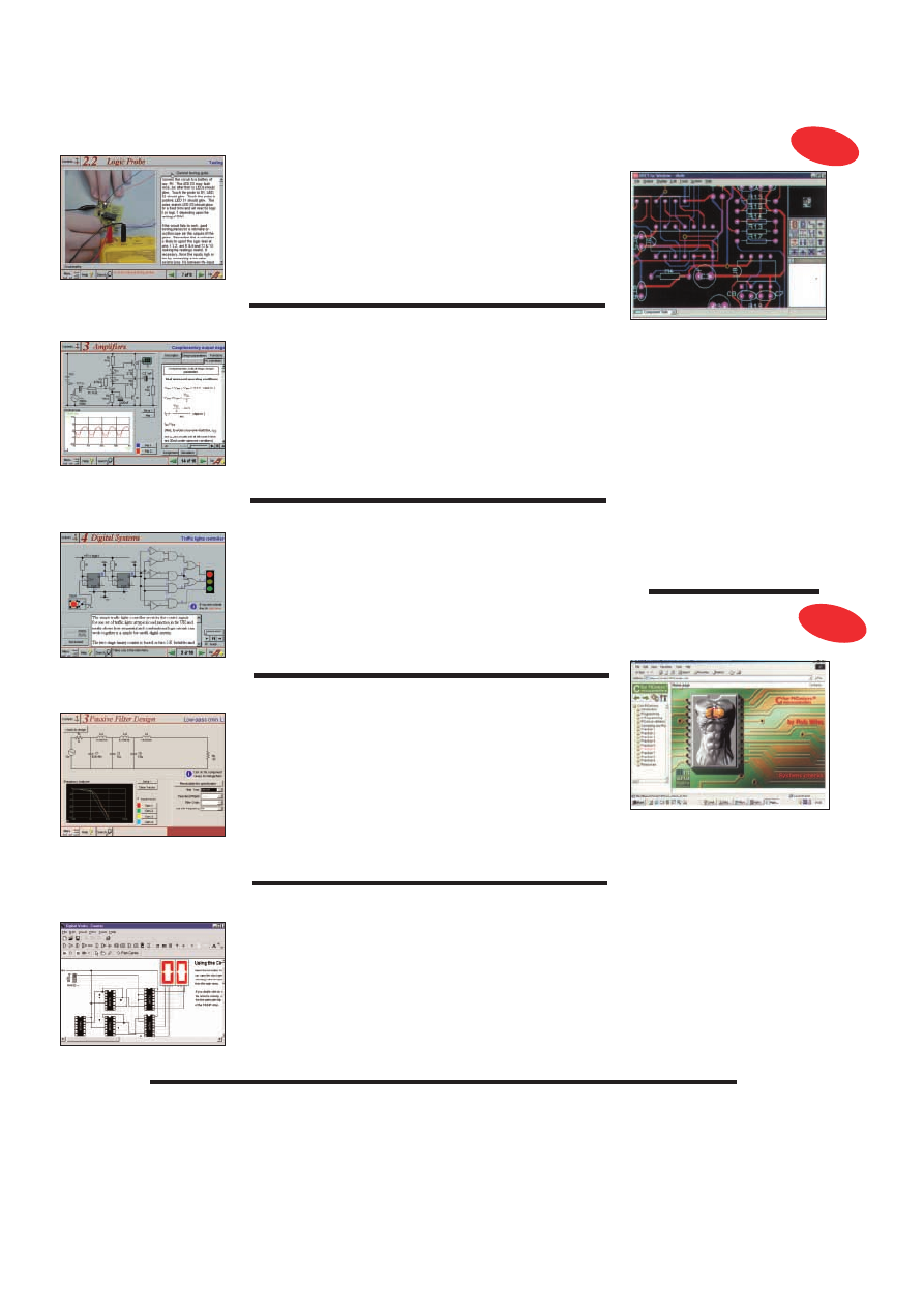
Prices for each of the CD-ROMs above are:
Hobbyist/Student ...................................................£45 inc VAT
Institutional (Schools/HE/FE/Industry)..............£99
plus VAT
Institutional 10 user (Network Licence) ..........£199
plus VAT
Complimentary output stage
Virtual laboratory – Traffic Lights
Digital Electronics builds on the knowledge of logic gates covered in Electronic
Circuits & Components (opposite), and takes users through the subject of
digital electronics up to the operation and architecture of microprocessors. The
virtual laboratories allow users to operate many circuits on screen.
Covers binary and hexadecimal numbering systems, ASCII, basic logic gates,
monostable action and circuits, and bistables – including JK and D-type flip-
flops. Multiple gate circuits, equivalent logic functions and specialised logic
functions. Introduces sequential logic including clocks and clock circuitry,
counters, binary coded decimal and shift registers. A/D and D/A converters,
traffic light controllers, memories and microprocessors – architecture, bus
systems and their arithmetic logic units.
(UK and EU customers add VAT at 17.5% to “plus VAT’’ prices)
Analogue Electronics is a complete learning resource for this most
difficult branch of electronics. The CD-ROM includes a host of virtual
laboratories, animations, diagrams, photographs and text as well as a
SPICE electronic circuit simulator with over 50 pre-designed circuits.
Sections on the CD-ROM include: Fundamentals – Analogue Signals (5
sections),Transistors (4 sections), Waveshaping Circuits (6 sections).
Op.Amps – 17 sections covering everything from Symbols and Signal
Connections to Differentiators. Amplifiers – Single Stage Amplifiers (8
sections), Multi-stage Amplifiers (3 sections). Filters – Passive Filters (10
sections), Phase Shifting Networks (4 sections), Active Filters (6 sections).
Oscillators – 6 sections from Positive Feedback to Crystal Oscillators.
Systems – 12 sections from Audio Pre-Amplifiers to 8-Bit ADC plus a
gallery showing representative p.c.b. photos.
Filters is a complete course in designing active and passive filters that
makes use of highly interactive virtual laboratories and simulations to
explain how filters are designed. It is split into five chapters: Revision which
provides underpinning knowledge required for those who need to design
filters. Filter Basics which is a course in terminology and filter
characterization, important classes of filter, filter order, filter impedance and
impedance matching, and effects of different filter types. Advanced Theory
which covers the use of filter tables, mathematics behind filter design, and
an explanation of the design of active filters. Passive Filter Design which
includes an expert system and filter synthesis tool for the design of low-
pass, high-pass, band-pass, and band-stop Bessel, Butterworth and
Chebyshev ladder filters. Active Filter Design which includes an expert
system and filter synthesis tool for the design of low-pass, high-pass, band-
pass, and band-stop Bessel, Butterworth and Chebyshev op.amp filters.
Digital Works Version 3.0 is a graphical design tool that enables you to
construct digital logic circuits and analyze their behaviour. It is so
simple to use that it will take you less than 10 minutes to make your
first digital design. It is so powerful that you will never outgrow its
capability.
)Software for simulating digital logic circuits
)Create your own macros – highly scalable
)Create your own circuits, components, and i.c.s
)Easy-to-use digital interface
)Animation brings circuits to life
)Vast library of logic macros and 74 series i.c.s with data sheets
)Powerful tool for designing and learning
Counter project
Filter synthesis
Everyday Practical Electronics
are pleased to be able to offer all readers these
ELECTRONICS CD-ROMS
FILTERS
DIGITAL WORKS 3.0
ANALOGUE ELECTRONICS
Logic Probe testing
ELECTRONICS PROJECTS
DIGITAL ELECTRONICS
PRICES
Electronic Projects is split into two main sections: Building Electronic Projects
contains comprehensive information about the components, tools and
techniques used in developing projects from initial concept through to final
circuit board production. Extensive use is made of video presentations showing
soldering and construction techniques. The second section contains a set of ten
projects for students to build, ranging from simple sensor circuits through to
power amplifiers. A shareware version of Matrix’s CADPACK schematic
capture, circuit simulation and p.c.b. design software is included.
The projects on the CD-ROM are: Logic Probe; Light, Heat and Moisture
Sensor; NE555 Timer; Egg Timer; Dice Machine; Bike Alarm; Stereo Mixer;
Power Amplifier; Sound Activated Switch; Reaction Tester. Full parts lists,
schematics and p.c.b. layouts are included on the CD-ROM.
ELECTRONICS
CAD PACK
Electronics CADPACK allows users to
design complex circuit schematics, to view
circuit animations using a unique SPICE-
based simulation tool, and to design
printed circuit boards. CADPACK is made
up of three separate software modules:
ISIS Lite which provides full schematic
drawing features including full control of
drawing appearance, automatic wire
routing, and over 6,000 parts. PROSPICE
Lite (integrated into ISIS Lite) which uses
unique animation to show the operation of
any circuit with mouse-operated switches,
pots. etc. The animation is compiled using
a full mixed mode SPICE simulator. ARES
Lite PCB layout software allows
professional quality PCBs to be designed
and includes advanced features such as
16-layer boards, SMT components, and
even a fully functional autorouter.
“C’’ FOR PICMICRO
MICROCONTROLLERS
C for PICmicro Microcontrollers is
designed for students and professionals
who need to learn how to use C to
program embedded microcontrollers. This
product contains a complete course in C
that makes use of a virtual C PICmicro
which allows students to see code
execution step-by-step. Tutorials, exercises
and practical projects are included to allow
students to test their C programming
capabilities. Also includes a complete
Integrated Development Environment, a full
C compiler, Arizona Microchip’s MPLAB
assembler, and software that will program
a PIC16F84 via the parallel printer port on
your PC. (Can be used with the
PICtutor
hardware – see opposite.)
Although the course focuses on the use of
the PICmicro series of microcontrollers,
this product will provide a relevant
background in C programming for any
microcontroller.
NEW
NEW
PCB Layout

Interested in programming PIC microcontrollers? Learn with
P
PIIC
Cttu
utto
orr
by John Becker
This highly acclaimed CD-ROM, together with the PICtutor experimental and development board, will teach
you how to use PIC microcontrollers with special emphasis on the PIC16x84 devices. The board will also act
as a development test bed and programmer for future projects as your programming skills develop. This
interactive presentation uses the specially developed Virtual PIC Simulator to show exactly what is
happening as you run, or step through, a program. In this way the CD provides the easiest and best ever
introduction to the subject.
Nearly 40 Tutorials cover virtually every aspect of PIC programming in an easy to follow logical sequence.
HARDWARE
Whilst the CD-ROM can be used on its own, the physical demonstration provided by the PICtutor
Development Kit, plus the ability to program and test your own PIC16x84s, really reinforces the lessons
learned. The hardware will also be an invaluable development and programming tool for future work.
Two levels of PICtutor hardware are available – Standard and Deluxe. The Standard unit comes with a battery
holder, a reduced number of switches and no displays. This version will allow users to complete 25 of the 39
Tutorials. The Deluxe Development Kit is supplied with a plug-top power supply (the Export Version has a
battery holder), all switches for both PIC ports plus l.c.d. and 4-digit 7-segment l.e.d. displays. It allows users
to program and control all functions and both ports of the PIC. All hardware is supplied fully built and tested
and includes a PIC16F84.
MODULAR CIRCUIT DESIGN
This CD-ROM contains a range of tried and tested analogue and digital
circuit modules, together with the knowledge to use and interface them.
Thus allowing anyone with a basic understanding of circuit symbols to
design and build their own projects.
Essential information for anyone undertaking GCSE or “A’’ level
electronics or technology and for hobbyists who want to get to grips
with project design. Over seventy different Input, Processor and Output
modules are illustrated and fully described, together with detailed
information on construction, fault finding and components, including
circuit symbols, pinouts, power supplies, decoupling etc.
Single User Version £19.95 inc. VAT
Multiple User Version £34
plus VAT
(UK and EU customers add VAT at 17.5% to “plus VAT’’ prices)
Minimum system requirements for these CD-ROMs: PC with 486/166MHz, VGA+256 colours, CD-ROM drive, 32MB RAM, 10MB hard disk space. Windows 95/98, mouse, sound card, web browser.
CD-ROM ORDER FORM
Electronic Projects
Analogue Electronics
Version required:
Digital Electronics
Hobbyist/Student
Filters
Institutional
Digital Works 3.0
Institutional 10 user
Electronics CAD Pack
C For PICmicro Microcontrollers
PICtutor
Electronic Circuits & Components +The Parts Gallery
PICtutor Development Kit – Standard
PICtutor Development Kit – Deluxe
Deluxe Export
Electronic Components Photos
Modular Circuit Design – Single User
Modular Circuit Design – Multiple User
Full name: . . . . . . . . . . . . . . . . . . . . . . . . . . . . . . . . . . . . . . . . . . . . . . . . . . . . . . . . . . . . . . . . . . . . . .
Address: . . . . . . . . . . . . . . . . . . . . . . . . . . . . . . . . . . . . . . . . . . . . . . . . . . . . . . . . . . . . . . . . . . . . . . . .
. . . . . . . . . . . . . . . . . . . . . . . . . . . . . . . . . . . . . . . . . . . . . . . . . . . . . . . . . . . . . . . . . . . . . . . . . . . . . .
. . . . . . . . . . . . . . . . . . . . . . . . . . . .Post code: . . . . . . . . . . . . . . . .Tel. No: . . . . . . . . . . . . . . . . . . . .
Signature: . . . . . . . . . . . . . . . . . . . . . . . . . . . . . . . . . . . . . . . . . . . . . . . . . . . . . . . . . . . . . . . . . . . . . . .
I enclose cheque/PO in £ sterling payable to WIMBORNE PUBLISHING LTD for £ . . . . . . . . . . . . . .
Please charge my Visa/Mastercard/Switch: £ . . . . . . . . . . . . .Card expiry date: . . . . . . . . . . . . . . . .
Card No: . . . . . . . . . . . . . . . . . . . . . . . . . . . . . . . . . . . . . . . . . . . . . . . . . . . Switch Issue No. . . . . . . .
ORDERING
ALL PRICES INCLUDE UK
POSTAGE
Student/Single User/Standard Version
price includes postage to most
countries in the world
EU residents outside the UK add £5
for airmail postage per order
Institutional,
Multiple User and Deluxe
Versions – overseas readers add £5 to the basic
price of each order for airmail postage (do not
add VAT unless you live in an EU country, then
add 17½% VAT or provide your official VAT
registration number).
Send your order to:
Direct Book Service
Allen House, East Borough, Wimborne
Dorset BH21 1PF
Direct Book Service is a division of Wimborne
Publishing Ltd. To order by phone ring
01202 881749. Fax: 01202 841692
Goods are normally sent within seven days
E-mail: orders@epemag.wimborne.co.uk
The Virtual PIC
Deluxe PICtutor Hardware
Note: The software on each
version is the same, only
the licence for use varies.
Note: The CD-ROM is not included
in the Development Kit prices.
ee50b
ELECTRONIC CIRCUITS & COMPONENTS
+ THE PARTS GALLERY
Provides an introduction to the principles and application of the most common types of
electronic components and shows how they are used to form complete circuits. The
virtual laboratories, worked examples and pre-designed circuits allow students to learn,
experiment and check their understanding. Sections include:
Fundamentals:
units &
multiples, electricity, electric circuits, alternating circuits.
Passive Components:
resistors, capacitors, inductors, transformers.
Semiconductors:
diodes, transistors,
op.amps, logic gates.
Passive Circuits . Active Circuits
The Parts Gallery
will help students to recognise common electronic components and
their corresponding symbols in circuit diagrams. Selections include:
Components,
Components Quiz, Symbols, Symbols Quiz, Circuit Technology
Hobbyist/Student...............................................................................£34 inc VAT
Institutional (Schools/HE/FE/Industry)............................................£89
plus VAT
Institutional 10 user (Network Licence)..........................................£169
plus VAT
(UK and EU customers add VAT at 17.5% to “plus VAT’’ prices)
Note: The software on each version is
the same, only the licence for use varies.
PICtutor CD-ROM
Hobbyist/Student . . . . . . . . . . . . . . . . . . . .£45 inc. VAT
Institutional (Schools/HE/FE Industry) . . .£99
plus VAT
Institutional 10 user (Network Licence) .£199
plus VAT
HARDWARE
Standard PICtutor Development Kit . . . . . . .£47 inc. VAT
Deluxe PICtutor Development Kit . . . . . . . .£99
plus VAT
Deluxe Export Version . . . . . . . . . . . . . . . . .£96
plus VAT
(UK and EU customers add VAT at 17.5% to “plus VAT’’ prices)
ELECTRONIC COMPONENTS PHOTOS
A high quality selection of over 200 JPG images of electronic components. This selection of high resolution photos can be used to enhance projects
and presentations or to help with training and educational material. They are royalty free for use in commercial or personal printed projects, and can
also be used royalty free in books, catalogues, magazine articles as well as worldwide web pages (subject to restrictions – see licence for full details).
Also contains a FREE 30-day evaluation of Paint Shop Pro 6 – Paint Shop Pro image editing tips and on-line help included!
Price
£19.95
inc. VAT
Please send me:

A Tasty Dish
A
RECENT
TV programme followed the progress of a number of
trainee chefs as they passed through a training school. The tutor
demonstrated how to turn out a certain dish which the students had
to re-create as accurately as possible in the allotted time. If it didn’t
quite look as they intended, they were told, it didn’t matter too
much because the customer would never know what the “proper”
dish was supposed to look like anyway!
I thought that this principle could apply to web design. Each web
browser has its own peculiarities in the way it can handle cascading
style sheets, tables, text, Javascript and more besides. A web site
optimised for one browser can look a mess in another, or on anoth-
er system. It is possible to use browser-sniffing scripts to detect the
type of browser being used, and direct the user to a suitable version
of the site developed for his web browser, but running several ver-
sions of a site just adds to the cost of its design and development.
A more realistic approach is to make the site look reasonably
“accurate” when viewed in any of the popular browsers on popular
platforms, and also try to design for a certain screen resolution, also
being mindful of any functionality needed (cookies, secure order-
ing, Javascript and so on). If a web site designer aims for a middle
ground, then there is a good chance that most of the users looking
in will see an acceptable version of the “dish”, especially as they
will probably never know what the dish was supposed to look like
anyway.
I sometimes check the web site statistics of my client sites, and I
can say that anything from 65 per cent up to 95 per cent of people
use Microsoft Internet Explorer 5. The rest use Netscape Navigator,
Opera or a small number of specialist text-based browsers.
Netscape 6.0
Netscape’s latest incar-
nation of its web browser
is now available for down-
load from their website at
w w w . n e t s c a p e . c o m
Navigator 6 has been
completely rebuilt from
the ground up, and uses
Netscape’s “Gecko”
engine, so by rights it’s a
Version One browser,
rather than a Version Six
upgrade. It has been coded
on an open-source basis.
“Netscape 6 is the most
s t a n d a r d s - c o m p l i a n t
browser ever released. It
is the first browser to
deliver the robust, consis-
tent, cross-platform web
standards support that
developers have been
demanding. It supports
more web standards, more
deeply, more consistently across platforms than any other browser,
and it’s being released simultaneously on Windows, Macintosh, and
Linux” says Netscape’s web site.
This standards compliance will come as a novelty to many
designers, who, like myself, have become accustomed to adapting,
scrapping and rewriting code to make it work properly in all the
popular browsers. In practice, the striving for compliance is a dou-
ble-edged sword though.
Not every web user will want to persevere with a download in
excess of 20MB from Netscape’s site: the first stage downloads a
small installer program after which various options can be selected
to customise the download. You can also choose the more sensible
option of downloading the re-installation files themselves, rather
than letting Netscape try to upgrade your system “on the fly”.
Installation Snags Overcome
I downloaded the 23MB needed to install Navigator 6. The file
transfer went flawlessly but worryingly, it wanted to de-install my
existing version of Netscape Navigator first, until I realised it actu-
ally referred to my beta version of Netscape 6 and not my older
Navigator 4.6. Then the installation routine stalled completely, forc-
ing me to reboot. Nevertheless the installation process was com-
pleted properly afterwards, and soon I was pointing Netscape’s new
browser towards various web sites.
The first thing I noticed was that it was somewhat slow to
launch, but before long I was greeted with a stylish window and
a multitude of navigation bars. Version 6 has configurable
“skins” or themes to adapt the appearance, or you can revert to
the classic Navigator style instead. A neat draggable sidebar can
be selected to fill with your choice of channels when you go
online, and it has a built-in Buddy List to keep track of friends
when on-line, and links to enable Net2Phone to be downloaded.
Furthermore, it imports Internet Explorer Favorites immediately,
a welcome feature. Many other features are available in the con-
figurable sidebar.
More problematic for designers, though, is that some current web
pages were broken up when viewed in Navigator 6. Some
Javascripted functions
failed to function prop-
erly and “sliced”
images – which are
arranged in tables –
were sometimes broken
up; furthermore the
new browser doesn’t
support certain func-
tions whatsoever.
If the pages have
been coded to obey the
rules, then in theory
there shouldn’t be a
problem, yet until now
designers have had
to
work with web
browsers that have
not been entirely com-
pliant:
now having
made web sites com-
patible with older
browsers,
we must
agonise over the more
strict rules-obedience
of Navigator 6 instead.
The challenge now is to code all pages precisely in accordance
with published HTML standards, and also make everything
backwards-compatible for the older generations of web
browsers as well. The hope is that ultimately we can eventually
dump our legacy web browsers and move onto something which
is stable, predictable and compliant, and in this respect Netscape
6 is a welcome move in the right direction. If only it had
happened five years ago.
SURFING THE INTERNET
NET WORK
ALAN WINSTANLEY
134
Everyday Practical Electronics, February 2001

OCT ’99
PROJECTS
)) Interior Lamp Delay ) Mains Cable
Detector
) QWL Loudspeaker System ) Micro
Power Supply.
FEATURES
) PIC16F87x Mini Tutorial ) Practical
Oscillator Designs–4
) Circuit Surgery ) Interface
) Ingenuity Unlimited ) Net Work – The Internet.
NOV ’99
PROJECTS
)) Acoustic Probe ) Vibralarm )
Ginormous Stopwatch–1
) Demister One-Shot.
FEATURES
) Teach-In 2000–Part 1 ) Ingenuity
Unlimited
) Practically Speaking ) Practical
Oscillator Designs–5
) Circuit Surgery ) New
Technology Update
) Net Work – The Internet
FREE
Identifying Electronic Components booklet.
DEC ’99
PROJECTS
)) PIC Micro-Probe ) Magnetic Field
Detector
) Loft Guard ) Ginormous Stopwatch –
Giant Display–2.
FEATURES
) Teach-In 2000–Part 2 ) Practical
Oscillator Designs–6
) Interface ) Ingenuity
Unlimited (Special)
) Circuit Surgery )
Network–The Internet
) 1999 Annual Index.
JAN ’00
PROJECTS
)Scratch Blanker ) Versatile Burglar
Alarm
) Flashing Snowman ) Vehicle Frost Box.
FEATURES
) Ingenuity Unlimited ) Teach-In
2000–Part 3
) Circuit Surgery ) Practically Speaking
) Tina Pro Review ) Net Work – The Internet.
FEB ’00
Photostats Only
PROJECTS
) PIC Video Cleaner ) Voltage
Monitor
) Easy-Typist Tape Controller ) Find It –
Don’t Lose It!
FEATURES
) Technology Timelines–1 ) Circuit
Surgery
) Teach-In 2000–Part 4 ) Ingenuity
Unlimited
) Interface ) Net Work – The
Internet.
MAR ’00
PROJECTS
) EPE ICEbreaker ) High
Performance Regenerative Receiver–1
)
Parking Warning System
) Automatic Train
Signal.
FEATURES
) Teach-In 2000 – Part 5 ) Practically
Speaking
) Technology Timelines–2 ) Ingenuity
Unlimited
) Circuit Surgery ) New Technology
Update
) Net Work – The Internet.
APRIL ’00
PROJECTS
) Flash Slave ) Garage Link ) Micro-
PICscope
) High Performance Regenerative
Receiver–2.
FEATURES
) Teach-In 2000–Part 6 ) Ingenuity
Unlimited
) Technology Timelines–3 ) Circuit
Surgery
) Interface ) Telcan Home Video ) Net
Work – The Internet.
MAY ’00
PROJECTS
) Versatile Mic/Audio Preamplifier
) PIR Light Checker ) Low-Cost Capacitance
Meter
)
Multi-Channel Transmission
System–1.
FEATURES
) Teach-In 2000–Part 7 )
Technology Timelines–4
) Circuit Surgery )
Practically Speaking
) Ingenuity Unlimited )
Net Work – The Internet
)
FREE
Giant
Technology Timelines Chart.
JUNE ’00
PROJECTS
)
Atmospheric Electricity
Detector–1
) Canute Tide Predictor ) Multi-
Channel Transmission System–2
) Automatic
Nightlight.
FEATURES
) Teach-In 2000 – Part 8 ) Technology
Timelines–5
) Circuit Surgery ) Interface ) New
Technology Update
) Ingenuity Unlimited ) Net
Work – The Internet.
JULY ’00
PROJECTS
)
g
-Meter
) Camera Shutter Timer
PIC-Gen Frequency Generator/Counter
) Atmos-
pheric Electricity Detector–2.
FEATURES
) Teach-In 2000–Part 9 ) Practically
Speaking
) Ingenuity Unlimited ) Circuit Surgery
) PICO DrDAQ Reviewed ) Net Work – The
Internet.
AUG ’00
PROJECTS
) Handy-Amp ) EPE Moodloop )Quiz
Game Indicator
)Door Protector
FEATURES
) Teach-In 2000–Part 10 ) Cave
Electronics
) Ingenuity Unlimited ) Circuit
Surgery
) Interface ) New Technology Update
)Net Work – The Internet.
SEPT ’00
PROJECTS
) Active Ferrite Loop Aerial )
Steeplechase Game
) Remote Control IR
Decoder
) EPE Moodloop Power Supply.
FEATURES
) Teach-In 2000–Part 11 ) New
Technology Update
) Circuit Surgery ) Ingenuity
Unlimited
) Practically Speaking ) Net Work –
The Internet Page.
OCT ’00
PROJECTS
) Wind-Up Torch ) PIC Dual-Chan
Virtual Scope
) Fridge/Freezer Alarm ) EPE
Moodloop Field Strength Indicator.
FEATURES
) Teach-In 2000–Part 12 ) Interface
)Ingenuity Unlimited ) New Technology Update
) Circuit Surgery ) Peak Atlas Component
Analyser Review
) Net Work – The Internet Page.
NOV ’00
PROJECTS
) PIC Pulsometer ) Opto-Alarm
System
) Sample-and-Hold ) Handclap Switch.
FEATURES
) The Schmitt Trigger–Part 1 )
Ingenuity Unlimited
) PIC Toolkit Mk2 Update
V2.4
) Circuit Surgery ) New Technology Update
) Net Work – The Internet ) FREE Transistor
Data Chart.
DEC ’00
PROJECTS
) PIC-Monitored Dual PSU-Part1 )
Static Field Detector
) Motorists’ Buzz-Box )
Twinkling Star
) Christmas Bubble ) Festive
Fader
) PICtogram.
FEATURES
) The Schmitt Trigger–Part 2 )
Ingenuity Unlimited
) Interface ) Circuit Surgery )
New Technology Update
)Quasar Kits Review )
Net Work – The Internet
) 2000 Annual Index.
JAN ’01
PROJECTS
) Versatile Optical Trigger ) UFO
Detector and Event Recorder
) Two-Way
Intercom
) PIC-Monitored Dual PSU–Part 2.
FEATURES
) Using PICs and Keypads ) The
Schmitt Trigger–Part 3
) New Technology Update
) Circuit Surgery ) Practically Speaking )
Ingenuity Unlimited
) CIRSIM Shareware Review
) Net Work – The Internet.
BBAACCKK IISSSSUUEESS
We can supply back issues of
EPE
by post, most issues from the past five years are available. An
EPE
index for the last five years is also available – see order form.
Alternatively, indexes are published in the December issue for that year. Where we are unable to provide a back issue a photostat of any
one article
(or
one part
of a
series) can be purchased for the same price. Issues from July 2000 onwards are also available to download from www.epemag.com.
BACK ISSUES
ONLY £3.00
each inc. UK p&p.
Overseas prices £3.50 each surface mail, £4.95 each airmail.
We can also supply issues from earlier years: 1992 (except March, April, June to Sept. and Dec.), 1993 (except Jan. to March, May,
Aug., Dec.), 1994 (except April to June, Aug., Oct. to Dec.), 1995 (No Issues), 1996 (except Jan. to May, July, Aug., Nov.), 1997 (except
Feb. and March), 1998 (except Jan., March to May, July, Nov., Dec.), 1999.
We can also supply back issues of
ETI (prior to the merger of the two magazines) for 1998/9 – Vol. 27 Nos 1 to 13 and Vol. 28
No. 1. We are not able to supply any material from
ETI prior to 1998. Please put ETI clearly on your order form if you require
ETI issues.
Where we do not have an issue a photostat of any
one article or one part of a series can be provided at the same price.
O
OR
RD
DE
ER
R F
FO
OR
RM
M – BACK ISSUES – PHOTOSTATS– INDEXES
1
Send back issues dates . . . . . . . . . . . . . . . . . . . . . . . . . . . . . . . . . . . . . . . . . . . . . . . . . . . . . . . . . . . . . . . . . . .
1
Send photostats of (article title and issues date) . . . . . . . . . . . . . . . . . . . . . . . . . . . . . . . . . . . . . . . . . . . . . . . . .
1
Send copies of last five years indexes (£3.00 for five inc. p&p – Overseas £3.50 surface, £4.95 airmail)
Name . . . . . . . . . . . . . . . . . . . . . . . . . . . . . . . . . . . . . . . . . . . . . . . . . . . . . . . . . . . . . . . . . . . . . . . . . . . . . . . . . . . .
Address . . . . . . . . . . . . . . . . . . . . . . . . . . . . . . . . . . . . . . . . . . . . . . . . . . . . . . . . . . . . . . . . . . . . . . . . . . . . . . . . . .
. . . . . . . . . . . . . . . . . . . . . . . . . . . . . . . . . . . . . . . . . . . . . . . . . . . . . . . . . . . . . . . . . . . . . . . . . . . . . . . . . . . . . . . .
1
I enclose cheque/P.O./bank draft to the value of £ . . . . . . . . . . . . . . . . . . . . . . . . . . . . . . . . . . . . . . . . . . . . . . . .
1
Please charge my Visa/Mastercard/Switch £ . . . . . . . . . . .
Switch Issue No. . . . . . . . . . . . . . . . . . . .
Card No. . . . . . . . . . . . . . . . . . . . . . . . . . . . . . . . . . . . . . . . . . . . . . .
Card Expiry Date . . . . . . . . . . . . . . . . . . .
Note: Minimum order for credit cards £5. Please supply name and address of cardholder if different from that shown above.
SEND TO: Everyday Practical Electronics, Allen House, East Borough, Wimborne, Dorset BH21 1PF.
Tel: 01202 881749. Fax: 01202 841692.
E-mail: orders@epemag.wimborne.co.uk
Payments must be in £ sterling – cheque or bank draft drawn on a UK bank. Normally supplied within seven days of receipt of order.
Send a copy of this form, or order by letter if you do not wish to cut your issue.
M02/01
Everyday Practical Electronics, February 2001
135
D
DIID
D Y
YO
OU
U M
MIIS
SS
S T
TH
HE
ES
SE
E?
?

S
ST
TO
OR
RE
E Y
YO
OU
UR
R B
BA
AC
CK
K IIS
SS
SU
UE
ES
S IIN
N Y
YO
OU
UR
R W
WA
AL
LL
LE
ET
T!!
A great way to buy
EPE Back Issues – our wallet-sized
CD-ROMs contain back issues from our
EPE Online website plus
bonus articles, all the relevant PIC software and web links.
All this for just £12.45 each including postage and packing.
VOL 1 CONTENTS
BACK ISSUES – November 1998 to June 1999 (all the projects,
features, news, IUs etc. from all eight issues). Note: No advertise-
ments or Free Gifts are included.
PIC PROJECT CODES – All the available codes for the PIC based
projects published in issues from November 1998 to June 1999.
EPE ONLINE STORE – Books, PCBs, Subscriptions, etc.
VOL 2 CONTENTS
BACK ISSUES – July 1999 to December 1999 (all the projects, fea-
tures, news, IUs, etc. from all six issues). Note: No advertisements
or Free Gifts are included.
PIC PROJECT CODES – All the available codes for the
PIC-based projects published in issues from July to
December 1999.
EPE ONLINE STORE – Books, PCBs, Subscriptions, etc.
VOL 3 CONTENTS
BACK ISSUES – January 2000 to June 2000 (all the projects,
features, news, IUs, etc. from all six issues). Note: No advertise-
ments or Free Gifts are included.
PIC PROJECT CODES – All the available codes for the PIC-based
projects published in issues from January to June 2000.
EXTRA ARTICLES – ON ALL VOLUMES
BASIC SOLDERING GUIDE – Alan Winstanley’s internationally
acclaimed fully illustrated guide.
UNDERSTANDING PASSIVE COMPONENTS – Introduction to the
basic principles of passive components.
HOW TO USE INTELLIGENT L.C.Ds, By Julyan Ilett – An utterly
practical guide to interfacing and programming intelligent liquid
crystal display modules.
PhyzzyB COMPUTERS BONUS ARTICLE 1 – Signed and
Unsigned Binary Numbers. By Clive “Max” Maxfield and
Alvin Brown.
PhyzzyB COMPUTERS BONUS ARTICLE 2 – Creating an Event
Counter. By Clive “Max” Maxfield and Alvin Brown.
INTERGRAPH COMPUTER SYSTEMS 3D GRAPHICS – A
chapter from Intergraph’s book that explains computer graphics
technology in an interesting and understandable way with full colour
graphics.
EXTRA ARTICLE ON VOL 1 & 2
THE LIFE & WORKS OF KONRAD ZUSE – a brilliant pioneer in
the evolution of computers. A bonus article on his life and work
written by his eldest son, including many previously unpublished
photographs.
BACK ISSUES CD-ROM ORDER FORM
Please send me ........ (quantity) BACK ISSUES CD-ROM VOL 1
Please send me ........ (quantity) BACK ISSUES CD-ROM VOL 2
Please send me ....... (quantity) BACK ISSUES CD-ROM VOL 3
Price £12.45 (approx $20) each – includes postage to anywhere
in the world.
Name . . . . . . . . . . . . . . . . . . . . . . . . . . . . . . . . . . . . . . . . . . . .
Address . . . . . . . . . . . . . . . . . . . . . . . . . . . . . . . . . . . . . . . . . .
. . . . . . . . . . . . . . . . . . . . . . . . . . . . . . . . . . . . . . . . . . . . . . . .
. . . . . . . . . . . . . . . . . . . . . . . . . . Post Code . . . . . . . . . . . . .
$I enclose cheque/P.O./bank draft to the value of £ . . . . . . . . .
$Please charge my Visa/Mastercard/Switch £ . . . . . . . . . . . . .
Card No. . . . . . . . . . . . . . . . . . . . . . . . . . . . . . . . . . . . . . . . . .
Expiry Date . . . . . . . . . . . . . . . . . . Switch Issue No. . . . . . . .
Note: Minimum order for cards £5.
SEND TO: Everyday Practical Electronics, Allen House,
East Borough, Wimborne, Dorset BH21 1PF.
Tel: 01202 881749.
Fax: 01202 841692.
E-mail: orders@epemag.wimborne.co.uk
Payments must be by card or in £ Sterling – cheque or bank
draft drawn on a UK bank.
Normally supplied within seven days of receipt of order.
Send a copy of this form, or order by letter if you do not wish to
cut your issue.
Order on-line from www.epemag.com or by
Phone, Fax, E-mail or Post
136
Everyday Practical Electronics, February 2001
ONLY
£
£1
12
2..4
45
5
each
including VAT
and p&p
V
VO
OLL 33
N
NO
OW
W AAVVAAIILL
A
AB
BLLEE
NOTE: This mini CD-ROM is suitable for use on any
PC with a CD-ROM drive. It requires Adobe Acrobat
Reader (available free from the Internet –
www.adobe.com/acrobat)
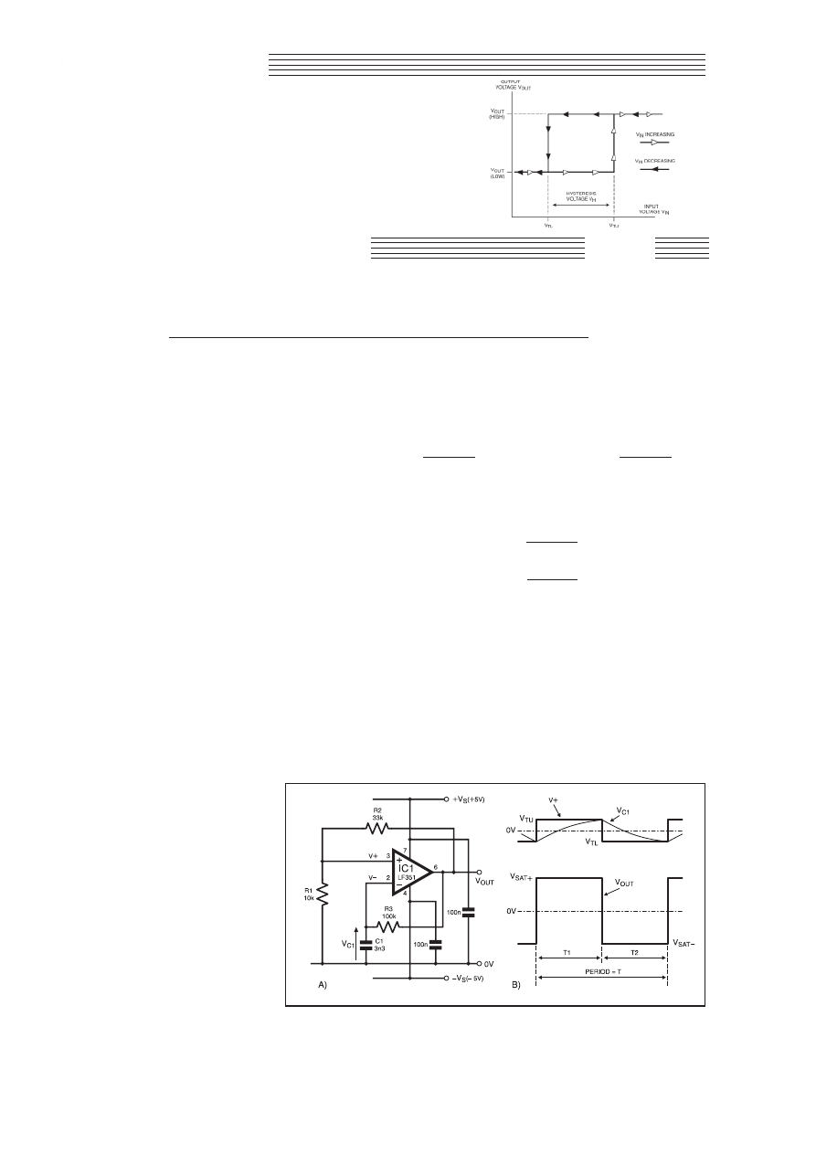
L
AST
month, in Part Three of this series, we saw how the
Schmitt trigger can be used as the central element in mono-
stable and bistable multivibrator circuits. This month, we’ll
look at the third member of the multivibrator family, the astable
multivibrator, and we’ll see how it can be adapted to form a pulse
width modulator. We’ll also examine the use of hysteresis in gener-
ating triangle waves, and we’ll investigate the Schmitt’s important
role as an interface for sensor devices.
TIME FOR SOME RELAXATION . . .
Both the monostable and bistable multivibrators examined last
month have at least one stable state, i.e., they remain in a constant,
stable state until “triggered’’ by an external signal. The astable
multi-vibrator, on the other hand, has no stable state: the circuit
alternates from one state to another, and continues to oscillate
without need of any external trigger signals.
The astable falls into a class of oscillators known as relaxation
oscillators, circuits in which the voltages or currents change sud-
denly at least once during each cycle. The circuit diagram of a sim-
ple, dual-rail astable, using the LF351 op.amp as a comparator, is
shown in Fig.4.1a. Note how the circuit has both positive feedback
(essential to the Schmitt trigger function), and negative feedback
applied via resistor R3. We can understand how the astable works
by referring to the circuit waveforms in Fig.4.1b.
Assume that IC1’s output voltage, V
OUT
, is at its positive satura-
tion level, V
SAT+
. The potential V+ at the non-inverting input (pin 3)
will sit at a positive level defined by V
SAT+
, resistor R1 and R2. This
is the upper threshold voltage, V
TU
. During the period T1, the volt-
age V
C1
on timing capacitor C1 will increase, exponentially, in a
positive direction as C1 is charged via timing resistor R3.
. . . AND REGENERATION
Eventually, when V
C1
just exceeds V
TU
, the
comparator “trips’’ and V
OUT
starts to go nega-
tive. The positive feedback provided by resis-
tor R2 provides the familiar regenerative
action which ensures that V
OUT
rapidly travers-
es from positive saturation to negative satura-
tion, denoted V
SAT–
.
During period T2, V
C1
starts to decrease as
capacitor C1’s electric field begins to “relax’’
and the energy stored in it starts to dissipate.
However, the process does not stop when the
voltage on capacitor C1 reaches zero; instead,
V
C1
becomes increasingly negative as C1
charges toward V
SAT–
.
During this time, the non-inverting input
voltage, V+ , sits at a negative level, V
TL
, the
lower threshold voltage. When the negative
voltage on C1 just exceeds V
TL
, the compara-
tor trips again and V
OUT
rapidly returns to its
positive saturation level, V
SAT+
. The process
now repeats, and V
OUT
alternates between its
two, unstable states at a frequency determined by capacitor C1 and
resistor R3.
Essentially, the circuit is simply a dual-rail, inverting Schmitt
trigger with thresholds set by resistors R1 and R2 as described in
Part Two of this series:
V
TU
=
R1 × V
SAT+
(volts),
and:
V
TL
=
R1 × V
SAT–
(volts)
R1 + R2
R1 + R2
However, the circuit effectively provides its own input in the
form of the exponentially varying voltage on C1. The “mark’’ and
“space’’ time periods, T1 and T2, are given by:
T1 =
Jln
{
V
SAT+
–V
TL
}
(seconds),
V
SAT+
–V
TU
and: T2 =
Jln
{
V
SAT–
–V
TU
}
(seconds),
V
SAT–
–V
TL
where the time constant
J= (C1 × R3) (seconds), and ln represents
the natural logarithm.
ASYMMETRICAL OUTPUT LEVELS
The circuit was built using the component values as shown in
Fig.4.1a. With the supply rails set to +V
S
= +5V and –V
S
= –5V, the
output saturation levels were found to be V
SAT+
= +4·20V and V
SAT–
= 3·65V. Using the equations given above, the thresholds should be
V
TU
= +0·979V and V
TL
= –0·850V. The actual values, measured by
observing the voltage levels at the non-inverting input (pin 3), were
V
TU
= +0·98V and V
TL
= –0·86V.
With C1 = 3·3nF and R3 = 100k
9, J= 0·33ms. Therefore, using
the measured values for V
SAT+
, V
SAT–
, V
TU
and V
TL
, the equations for
periods T1 and T2 yield values of 149µs and 167µs, respectively.
SSppeecciiaall SSeerriieess
THE SCHMITT
TRIGGER
In this short series, we investigate the Schmitt trigger’s operation; explore the various
ways of implementing its special characteristics and also look at how we can use it to
create oscillators and pulse width modulators.
Astable, PWM, Triangle Waveforms, Transducer Interface
138
Everyday Practical Electronics, February 2001
ANTHONY H. SMITH
Part 4
Fig.4.1(a). Astable multivibrator based on a Schmitt trigger and (b) circuit waveforms.
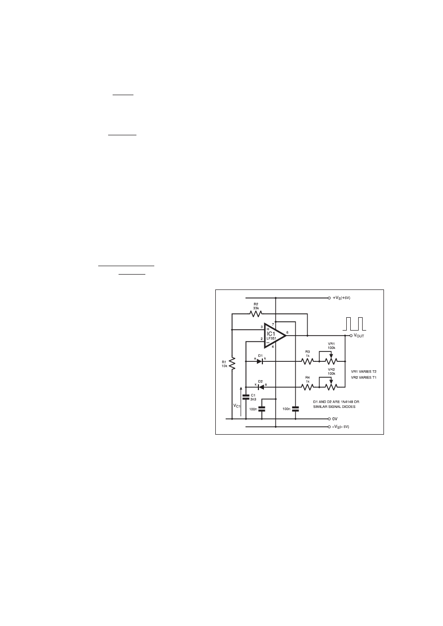
The measured values were T1 = 144µs and T2 = 160µs. The fact that
T1 does not equal T2 is due to the asymmetry in the output satura-
tion levels, which also results in the magnitude of the thresholds
being unequal. Whether or not this unequal mark-space ratio is a
problem depends entirely on the application.
DUTY CYCLE
The mark-space ratio of a rectangular waveform is more proper-
ly expressed in terms of duty cycle, where:
Duty Cycle =
T1
× 100%
T1 + T2
In the above case, we see that the output duty cycle is
144µs/(144µs + 160µs) = 47·4%. If we can adapt the circuit such
that V
SAT+
= –V
SAT–
, and hence V
TU
= –V
TL
, we find that:
T1 = T2 =
Jln
{
V
SAT+
+V
TU
}
(seconds)
V
SAT+
–V
TU
resulting in a 50% duty cycle.
One way to achieve this is to use an op.amp with “rail-to-rail’’
output swing, whereby V
OUT
swings to within a few millivolts of
each supply rail. Provided IC1’s output is lightly loaded and the
magnitudes of the supply rails are equal, this approach ensures that
|
V
SAT+
|
=
|
V
SAT–
|
. If a rail-to-rail op.amp is not available, consider
the use of output “clamping’’ using back-to-back Zener diodes or a
diode bridge arrangement, both of which were described in Part
Two.
The astable’s oscillation frequency is given by
Frequency, f = 1/T
where T is the period of the output cycle. Since T = T1 + T2, it fol-
lows that when T1 = T2, the frequency is simply f = 1/(2 × T1), and
can be found from:
Frequency, f =
1
(Hz)
2
Jln
{
V
SAT+
+V
TU
}
V
SAT+
–V
TU
Clearly, the frequency can be increased either by reducing
J,
or by decreasing the size of the threshold voltages. More about
this later.
CHOICE OF OP.AMP
The LF351 is a good choice of op.amp for use in multivibrators
like the one in Fig.4.1. Although it does not provide “rail-to-rail’’
performance, it is a reasonably fast device with good slew rate (typ-
ically 13V/µs), and its j.f.e.t. input stage results in very low input
bias currents.
With capacitor C1 = 3·3nF and resistor R3 = 100k
9, the circuit
produced a well-shaped rectangular output at just over 3kHz.
Reducing R3 to 10k
9 increased the frequency to just under 30kHz,
and although the output shape was still good, the measured values
of T1 and T2 were somewhat different from the calculated values
due to changes in the thresholds resulting from the effects of finite
bandwidth.
Reducing C1 to 330pF increased the frequency to 150kHz,
although the edges of the output waveform were noticeably sloped.
With C1 = 100pF, the frequency was just over 300kHz, but the out-
put waveshape was now “trapezoidal’’. Although the LF351 has a
unity-gain bandwidth of around 4MHz, its ability to generate
“sharp’’ square waves at frequencies above 100kHz is limited by the
effects of finite slew-rate.
LOW FREQUENCIES
Generating low frequency waveforms requires a large time con-
stant. To some degree, this can be achieved by maximising capaci-
tor C1, although for a bipolar astable like the one in Fig.4.1, where
V
C1
swings both positive and negative, C1 must be a non-polarised
type, which limits the maximum capacitance available. (Although
large-value, non-polarised electrolytic capacitors are available, they
often have relatively large leakage currents which can affect the cir-
cuit’s operation quite considerably).
At first sight, selecting a large value for resistor R3 would appear
to be the simplest way of maximising
J, especially as resistance val-
ues up to 10M
9 are readily available. However, the effects of input
bias current, I
B
, flowing into (or out of) the inverting input should
not be ignored, especially where accurate control of frequency and
duty cycle are required.
For example, let’s say we built the astable using an op.amp with
an input bias current of around 200nA (not uncommon for devices
like the LM358 or 741). When R3 is small (<100k
9), the bias cur-
rent has negligible effect on the charging and discharging of C1.
However, when R3 is in the region of 1M
9 or more, the input bias
current becomes relatively large compared to the current flowing
through R3, and effectively “unbalances’’ the charging action. (The
capacitor leakage currents mentioned above can have a similar
effect). Although this will not stop the astable oscillating, it can
have a marked effect on duty cycle and frequency.
Fortunately, the LF351’s very low input bias current (typically
just 50pA at room temperature) permits the use of large values for
resistor R3 with little effect on performance. For instance, with C1
= 1µF (non-polarised) and R3 = 1M
9, the circuit of Fig.4.1 pro-
duced a square wave with period T = 0·954s and pulse width T1 =
0·449s. At 47%, the duty cycle was just short of the 50% needed for
a perfectly “symmetrical’’ square wave, but this was due to the
unequal magnitudes of V
SAT+
and V
SAT–
, not to the effects of input
bias current.
COMMON MODE INPUT RANGE
The LF351 is just one of many op.amps available with low input
bias currents. Other devices with low I
B
are the Harris/Intersil
CA3140 (single; I
B
= 10pA typ.); the National Semiconductor
LMC662 (dual; I
B
= 0·002pA typ.); the Motorola MC33182 (dual;
I
B
= 30pA typ.); and the Texas Instruments TLC27L2 (dual; I
B
=
0·7pA typ.). There are many others to choose from.
Another important input parameter that should not be overlooked
when designing any op.amp or comparator circuit is the common
mode input voltage range. As we saw in Part Two, the common
mode input voltage range defines the allowable input voltage that
can be tolerated by the device without malfunction.
When operating on ±5V supplies, the LF351’s common mode
range is typically +5V, –2V. Therefore, resistors R1 and R2
(Fig.4.1) should be selected to ensure that the voltage, V+, at the
non-inverting input (pin 3) terminal (and, hence, at the inverting
input (pin 2)) cannot go outside this range, otherwise the op.amp
might not function properly. With R1 = 10k
9 and R2 = 33k9, V+
will not exceed ±1·2V even if V
OUT
swings as much as ±5V.
VARIABLE PULSE GENERATOR
The simple astable of Fig.4.1 can easily be adapted to produce a
rectangular output with widely variable duty cycle. The required
modifications are shown in the circuit diagram Fig.4.2, where R3
has been replaced by the diode/resistor network comprising D1, D2,
R3, R4, VR1 and VR2.
The presence of the diodes allows capacitor C1 to be charged
and discharged at different rates. For example, when V
OUT
is high
(at V
SAT+
), C1 charges via D2, R4 and potentiometer VR2. Diode
D1 is reverse biased, so only R4 and VR2 control the charging
current flowing into C1, and hence determine the width of the
time period T1.
When V
OUT
goes low (to V
SAT–
), D2 becomes reverse biased and
C1 discharges via D1, R3 and VR1. Consequently, R3 and VR1 now
dictate the rate of discharge, and hence control the width of T2.
Everyday Practical Electronics, February 2001
139
Fig.4.2. Circuit modifications to the astable results in a
Variable Width Pulse Generator.
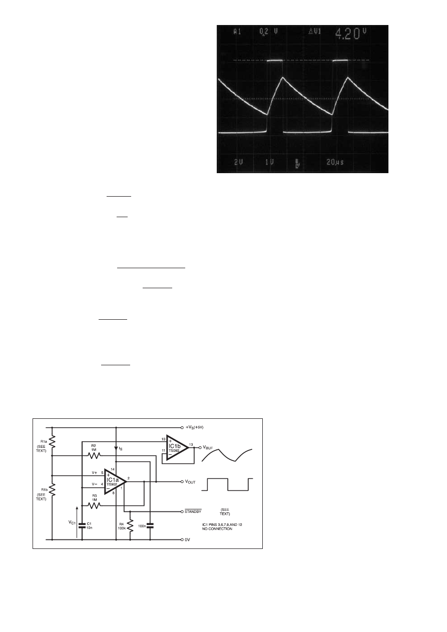
Typical waveforms generated by the Variable Width Pulse
Generator circuit are shown in Fig.4.3, obtained with C1 = 3·3nF,
R3 plus VR1 = 30k
W, and R4 plus VR2 = 10kW. The exponential
waveform, V
C1
, shows how capacitor C1 charges rapidly and then
discharges relatively slowly, resulting in T1 = 18·8µs and T2 =
59·2µs.
Potentiometers VR1 and VR2 provide independent control of T1
and T2, and with the values shown allow the duty cycle to be var-
ied from around 1·5% to 98·5%. By switching in different values of
C1, say in decade ranges from 1nF to 10µF, the circuit is capable of
producing pulse widths ranging from around 1µs to over half a
second.
SINGLE RAIL ASTABLE
A single rail version of the astable multivibrator is shown in
Fig.4.4. Using an op.amp like the TS902 having rail-to-rail input
and output swings simplifies the design procedure. Provided the
output is not heavily loaded, V
OUT
will swing from 0V to +V
S
,
removing any ambiguity about the values of V
SAT–
and V
SAT+
.
Furthermore, there is no need to worry about the input signals, V+
and V–, straying outside the common mode input voltage range.
Since V
OUT
swings rail-to-rail, we can assume that V
SAT–
= 0V
and V
SAT+
= +V
S
, and making these substitutions in the equations for
T1 and T2 quoted previously for the dual-rail astable, we find that:
T1 =
t ln
{
+V
S
–V
TL
}
(seconds)
+V
S
–V
TU
and: T2 =
t ln
{
V
TU
}
(seconds)
V
TL
where the time constant
t = (C1 × R3) (seconds).
Since the circuit is basically an adaptation of the single rail
Schmitt trigger described in Part Two, the threshold voltages, V
TU
and V
TL
are given by:
Upper Threshold Voltage, V
TU
=
(V
REF
× R2) + (+V
S
× R
TH
)
(volts)
R
TH
+ R2
and:
Lower Threshold Voltage, V
TL
=
(V
REF
× R2)
(volts)
R
TH
+ R2
where R
TH
is the Thévenin equivalent resistance of the R1a-R1b
potential divider:
R
TH
=
R1a × R1b
(ohms)
R1a + R1b
and V
REF
is the reference voltage generated by the potential
divider R1a-R1b and the positive supply:
V
REF
=
+V
S
× R1b
(volts)
R1a + R1b
Introducing R
TH
and V
REF
allows us to represent the single rail
astable with its equivalent circuit shown in Fig.4.5a. We will con-
sider the equivalent circuit in more detail, shortly. First, we’ll exam-
ine the performance of the Single Rail Astable with voltage fol-
lower circuit – shown in Fig.4.4.
POWER SAVING
Although not exceptionally fast (the slew rate is typically
0·8V/µs), the STMicroelectronics TS902 has very low input bias
current (I
B
= 1pA typ.) which, as we have seen, is important when
using large resistance values. It also features a “standby’’ function,
whereby its current consumption can be reduced to a minimal level
to save power. More about this later.
Since the resistance values in Fig.4.4 are large, it is important not
to “load’’ the circuit nodes when probing the waveforms. Even using
a ’scope probe with a 10M
W input impedance would significantly
load the op.amp inputs and would affect the astable’s operation.
This can be avoided by connecting the second half of the dual
TS902 as a voltage follower (IC1b) which “buffers’’ the sensitive
nodes. By connecting the follower to either of IC1a’s inputs, the
threshold levels and exponential waveform can be observed by con-
necting the ’scope probe to IC1b’s low-impedance output. Note,
however, that the signals will be “shifted’’ by IC1b’s input offset
voltage, which can be as much as ±10mV.
CIRCUIT PERFORMANCE
Initially, the Single Rail Astable (Fig.4.4) circuit was built with
R1a = R1b = 200k
W. With C1 = 10nF and R3 = 1MW, the time con-
stant
t = 10ms. With +V
S
= +5V, the theoretical values of T1 and
T2 calculated using the equations earlier are T1 = 1·82ms and T2 =
1·82ms. The actual, measured values were T1 = 1·90ms and T2 =
1·91ms, equivalent to a duty cycle of 49·9%.
Next, with R1a = 150k
W and R1b = 300kW, the measured values
were T1 = 2·75ms and T2 = 1·47ms, corresponding to a duty cycle
of 65·2%. The calculated values are T1 = 2·63ms and T2 = 1·40ms.
Finally, with R1a = 300k
W and R1b = 150kW, the measured val-
ues were T1 = 1·45ms and T2 = 2·75ms, corre-
sponding to a duty cycle of 34·5%. The calcu-
lated values are T1 = 1·40ms and T2 = 2·63ms.
Clearly, the measured results are in close
agreement with the theoretical values.
However, it is the variation in duty cycle which
is most interesting. For the case where resistors
R1a and R1b have equal values of 200k
W, the
equivalent value of V
REF
was 2·5V, i.e., 50% of
+V
S
, and the duty cycle was 49·9%.
When R1a = 150k
W and R1b = 300kW, the
equivalent value of V
REF
was 3·333V, i.e.,
66·7% of +V
S
, and the duty cycle was 65·2%.
Lastly, when R1a = 300k
W and R1b = 150kW,
the equivalent value of V
REF
was 1·667V, i.e.,
33·3% of +V
S
, and the duty cycle was 34·5%.
Notice that for each case the duty cycle
varies linearly with V
REF
and is almost directly
proportional to V
REF
as a percentage of +V
S
.
Furthermore, the value of R
TH
is 100k
W for
each case, i.e., only V
REF
varies from one case
to another, all other values remain constant.
140
Everyday Practical Electronics, February 2001
Fig.4.4. Circuit diagram for a Single-Rail Astable with voltage follower.
Fig.4.3. Pulse Generator Waveforms. Pulse waveform is V
OUT
(2V/div.). Exponential waveform is timing capacitor voltage,
V
C1
(1V/div.). Timebase: 20
ms/div.

Clearly, V
REF
is controlling the duty cycle, an
important finding that we’ll investigate shortly.
SUPPLY CURRENT AND
FREQUENCY
With resistors R1a and R1b at 200k
9, R3 at
1M
9 and capacitor C1’s value changed to
100nF, Fig.4.4’s circuit produced an output
frequency of 27·5Hz. Decreasing C1 by two
decades to 1nF increased the output frequency
to 2275Hz, roughly a hundred-fold increase.
The upper limit is about 15kHz: at higher fre-
quencies, the output waveform takes on a
“trapezoidal’’ shape because the TS902 does
not have the slew rate necessary to produce
rectangular waveforms beyond 20kHz.
It is a fact of life that all circuits, whether
linear or digital, tend to consume more power
at higher operating frequencies; consequently,
the supply current is also greater. The predom-
inant reason for this increase is that capacitances, either external to
the active device (like C1), or internal (such as junction capaci-
tances), must be charged and discharged every cycle.
Excessive supply current can be a major problem, especially in
battery-powered systems where battery life is inversely proportion-
al to power consumption. Clearly, one way to reduce current drain
is to use smaller capacitances wherever possible.
For instance, with C1 shorted out to make V
OUT
continually high,
the average current taken by Fig.4.4’s circuit was 222µA. This is the
“static’’ or “quiescent’’ operating current. Then, with C1 = 1nF and
R3 = 1M
9, such that J= 1ms, the astable oscillated at 2275Hz and
the average supply current was 332µA, an increase of 110µA on the
static value.
However, with C1 = 100nF and R3 = 10k
9 (J = 1ms), the astable
again oscillated at 2275Hz but the supply current was 426µA, an
increase of 204µA on the static value. Clearly, the increase in cur-
rent has almost doubled compared to the case above, even though
the time constant, and hence the operating frequency, remain the
same.
A DISABLING FEATURE
Another way to reduce the circuit current drain is to switch off
any sections that aren’t required. In a notebook computer, for exam-
ple, the processor can “power down’’ the internal modem when not
in use, thereby conserving battery energy. Even in relatively small
circuits, switching off any sub-circuit that is not needed will reduce
the average power consumption.
The TS902 dual op.amp provides a “standby’’ feature which
makes it easy to reduce current drain. When the STANDBY termi-
nal (pin 1) is high (connected to +V
S
), the op.amps function nor-
mally. However, if STANDBY is pulled low (to 0V), both op.amps
in the package are “disabled’’ and the outputs go to a high imped-
ance state.
The effect on the astable’s current consumption is quite dramat-
ic. For instance, with C1 = 100nF and R3 = 10k
9, and with
STANDBY high (circuit oscillating at 2275Hz), the op.amp supply
current, I
S
, was 420µA. However, with STANDBY pulled low, the
circuit stopped oscillating and I
S
fell to just 13µA.
FREQUENCY STABILITY
For precision applications demanding high frequency stability, a
crystal-controlled oscillator would be a better choice than the
astable of Fig.4.4. Nevertheless, when an op.amp or comparator
with rail-to-rail output swing is used, the astable’s operating fre-
quency and duty cycle remain remarkably constant with changes in
supply voltage.
For example, using one half of the rail-to-rail LMC6762 dual
comparator for IC1a, and with C1 = 10nF and R3 = 100k
9, the cir-
cuit’s frequency and duty cycle were measured as 2539Hz and
49·94% with +V
S
at +5V. With +V
S
increased to +15V, the values
were 2549Hz and 50·27%. The fact that the frequency and duty
cycle changed by less than one per cent is due to a “balancing’’
effect between the switching thresholds and charging current.
As the supply voltage increases, V
OUT
, and hence the charging
current into C1, also increase, and so C1 charges and discharges
more quickly. However, the increase in +V
S
causes a corresponding
increase in hysteresis voltage (the difference between V
TU
and V
TL
),
such that C1 has “further’’ to charge and discharge. The net effect is
that T1 and T2 remain fairly constant with changes in +V
S
.
PULSE WIDTH MODULATION
We saw how changing the relative values of resistors R1a and
R1b effectively varies the value of V
REF
and causes a corresponding
change in output duty cycle. If we dispense with R1a and R1b and
use a voltage source for V
REF
as shown in Fig.4.5a, V
REF
can then be
used to modulate the width of the output pulses.
Waveforms in Fig.4.5b shows C1’s voltage, V
C1
, when the capac-
itor charges and discharges between different thresholds. For the
case where V
C1
starts from V
TL
and charges to the relatively large
threshold voltage V
TU
(2), the waveform takes on the familiar “expo-
nential’’ shape. However, if the same capacitor is charged and dis-
charged with the same current over a relatively narrow range from
V
TL
to V
TU
(1), the waveform is much more “linear’’ and appears
almost triangular.
A circuit that can be built to experiment with the pulse width
modulator, where R1 and R2 set the thresholds, and C1 and R3
determine the time constant, is illustrated in Fig.4.6. This part of the
circuit is basically the same as that in Fig.4.5a, but with the equiv-
alent resistance R
TH
replaced by a real resistor, R1, and with equiv-
alent voltage V
REF
replaced by the modulating voltage V
MOD
.
Since the difference between V
TU
and V
TL
is the hysteresis volt-
age, V
H
, we can ensure that capacitor C1 charges over a narrow
range by making resistor R2 much larger than R1 such that V
H
is
very small compared to V
OUT
. This also results in the average volt-
age, V+, at the non-inverting input being approximately equal to
V
MOD
, that is: V+
≈ V
MOD
. Similarly, since V
C1
charges between the
thresholds established at the non-inverting input, the average volt-
age, V–, at the inverting input will also be approximately equal to
V
MOD
, that is: V–
≈ V
MOD
.
Therefore, during T1 when V
OUT
is at V
SAT+
, and C1 is charging
via R3, the charging current is simply: I
CHARGE
= (V
OUT
– V–)/R3,
or I
CHARGE
= (V
SAT+
– V
MOD
)/R3. Similarly, during T2 when V
OUT
is
at V
SAT–
, and C1 is discharging via R3, the discharging current is
simply: I
DISCHARGE
= (V
SAT–
– V
MOD
)/R3. If IC1b has a rail-
to-rail output swing, such that V
SAT+
= +V
S
and V
SAT–
= 0, then
I
CHARGE
= (+V
S
– V
MOD
)/R3 and I
DISCHARGE
= (–V
MOD
)/R3.
Now, the rate of change of voltage on a capacitor is given by:
,V
C
/
,t = I/C, where ,V
C
is the change in voltage,
,t is the time
period, I is the current and C is the capacitance. During T1, the volt-
age on C1 rises from V
TL
to V
TU
, and so
,V
C
= V
TU
– V
TL
= V
H
.
Therefore, V
H
/T1 = I
CHARGE
/C1. Rearranging and substituting for
I
CHARGE
we find that:
T1 =
V
H
× C1 × R3
(seconds).
+V
S
–V
MOD
Similarly, during T2, the voltage on C1 falls from V
TU
to V
TL
,
and so
,V
C
= V
TL
– V
TU
= –V
H
. Therefore, –V
H
/T2 = I
DISCHARGE
/C1.
Rearranging and substituting for I
DISCHARGE
we find that:
T2 =
V
H
× C1 × R3
(seconds).
V
MOD
Now, we saw earlier that
Duty Cycle =
T1
× 100%,
T1 + T2
and by substituting for T1 and T2, we find that:
Duty Cycle =
V
MOD
× 100%.
+V
S
Everyday Practical Electronics, February 2001
141
Fig.4.5(a). Equivalent circuit of the single rail astable, and (b) graph showing capac-
itor charging and discharging between different thresholds.
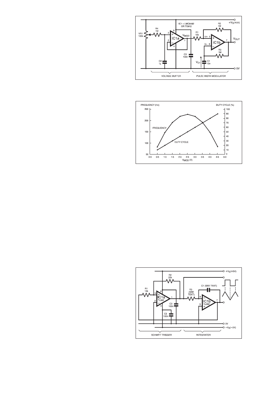
Clearly, the duty cycle is directly proportional to the modulating
voltage, V
MOD
. The circuit diagram of Fig.4.6 works well with most
dual, rail-to-rail op.amps having low input bias current; the
STMicroelectronics TS912 and National Semiconductor LMC6482
are good examples. In this circuit, a voltage follower, IC1a, buffers
the voltage on VR1’s wiper. The buffer is essential to ensure that
resistor R1 is driven from a low impedance voltage source. (If a
good quality, external d.c. voltage source is available, IC1a can be
omitted). IC1b could, of course, be a rail-to-rail comparator, but this
would require a separate op.amp to form the voltage follower.
Careful layout and proper decoupling are good practice when
“breadboarding’’ any of the circuits in this series. However, with resis-
tor R1 = 10k
9 and R2 = 1M9, the hysteresis voltage in Fig.4.6 is only
50mV, and so the slightest noise or interference can introduce signifi-
cant “jitter’’ to the output waveform. To minimise these problems,
make sure a good quality, “clean’’ d.c. power supply is used to gener-
ate +V
S
. Resistor R4 combined with capacitor C2 form a low-pass fil-
ter which removes any mains pickup on potentiometer VR1 wiper, and
capacitor C3 (which should be as close as possible to IC1) provides
decoupling for the op.amps. A large-value electrolytic capacitor, say
100µF, in parallel with C3 can also help.
LINEAR RELATIONSHIP
Pulse width modulators can be grouped into two categories: those
whose frequency remains constant as duty cycle is varied, and those
– like the circuit in Fig.4.6 – where both the duty cycle and output
frequency vary with V
MOD
.
The graphical results obtained using the TS912 dual op.amp for
IC1 are shown in Fig.4.7. Notice how the output frequency varies
considerably, peaking when V
MOD
= +V
S
/2, when T1 and T2 are
both at a minimum.
It is possible to use op.amps whose input and output voltage
swing extends from 0V to some voltage less than +V
S
. For exam-
ple, tests using the dual LM358 op.amp revealed an output swing
from 0V to 3·7V. Therefore, V
MOD
would be limited to a maximum
of 3·7V, although in practice the limit would be 3·5V since this is
the common mode input limit for a supply voltage of +5V. There is
still a linear relationship between duty cycle and V
MOD
, although
duty cycle is now proportional to V
MOD
as a fraction of V
SAT+
(the
positive output saturation voltage), not +V
S
.
Pulse Width Modulation (PWM) is a versatile and widely used
function in electronic systems, and finds uses in areas such as motor
control, switched mode power supplies and data transmission.
TRIANGULAR WAVES
Throughout this series we’ve seen how a triangular waveform
can be useful when testing the thresholds of a Schmitt trigger, so it’s
appropriate to describe how a Schmitt trigger can be used as part of
a triangle wave generator.
We saw in Fig.4.5b how the exponential voltage waveshape on a
capacitor can be made to appear triangular by limiting the range
over which the capacitor charges and discharges. This could be
achieved using the circuit in Fig.4.4 by making resistor R2 much
larger than the parallel combination of resistors R1a and R1b, such
that the hysteresis is very small compared to +V
S
. Then, by con-
necting IC1b as an amplifier rather than as a follower, the small
amplitude “pseudo-triangle’’ on C1 could be increased to a useful
magnitude.
The disadvantage of this approach is that the large gain required
(in the region of 50 to 100) would lead to problems with noise and
offsets, and in any event the output waveshape would never be truly
triangular.
FUNCTION GENERATOR
A more effective approach is shown in Fig.4.8, where a dual
op.amp is used to form a non-inverting Schmitt trigger and an inte-
grator. These two circuit elements are connected in a closed feed-
back loop known as a function generator where the Schmitt trigger
generates a square wave output, V
OUT(SQ)
, which forms the input to
the integrator, and the integrator generates a triangular output,
V
OUT(TRI)
, which is fed back to the input of the Schmitt.
Assume that the output of IC1a is in positive saturation, that is:
V
OUT(SQ)
= V
SAT+
. This voltage forces a positive current to flow into
resistor R3, and since no current flows into IC1b’s inverting input
(we can ignore the negligible input bias current), all of this current
must flow into capacitor C1.
Op.amp IC1b has negative feedback applied via C1; this means
that its output will go to whatever voltage is necessary to maintain
its inverting input, V–, at the same potential as its non-inverting
input, V+. Since V+ is at 0V, this means V– is forced to equal 0V,
also. Therefore, a constant current equal to V
SAT+
/R3 flows into R3
and then into C1.
Now, we saw earlier that when a capacitor is charged by a con-
stant current, its voltage varies linearly. Consequently, as the volt-
age on C1 increases linearly, IC1b’s output, V
OUT(TRI)
, must ramp
linearly in a negative direction to maintain V+ equal to V–.
Eventually, when V
OUT(TRI)
crosses the Schmitt’s lower threshold
voltage, IC1a’s output goes from positive to negative saturation, that
is V
OUT(SQ)
= V
SAT–
. This results in a constant, negative current equal
to V
SAT–
/R3 flowing into R3 and C1. Consequently, IC1b’s output
must now ramp linearly in a positive direction to maintain V– equal
to V+.
When V
OUT(TRI)
crosses the Schmitt’s upper threshold, IC1a’s out-
put, V
OUT(SQ)
, goes back into positive saturation, and the process
repeats. The resulting waveform at IC1b’s output is a triangle wave
which ramps between the Schmitt’s threshold levels, i.e., the ampli-
tude of V
OUT(TRI)
equals the hysteresis voltage, V
H
.
142
Everyday Practical Electronics, February 2001
Fig.4.6. Circuit diagram for an experimental Pulse Width
Modulator.
Fig.4.7. Graph showing the output frequency and duty cycle
versus modulation voltage for the Pulse Width Modulator
circuit using the TS912 op.amp.
Fig.4.8. Circuit diagram combining a Schmitt trigger and
integrator to form a Function Generator.
V–
V+
V
OUT(TR1)
V
OUT(SQ)
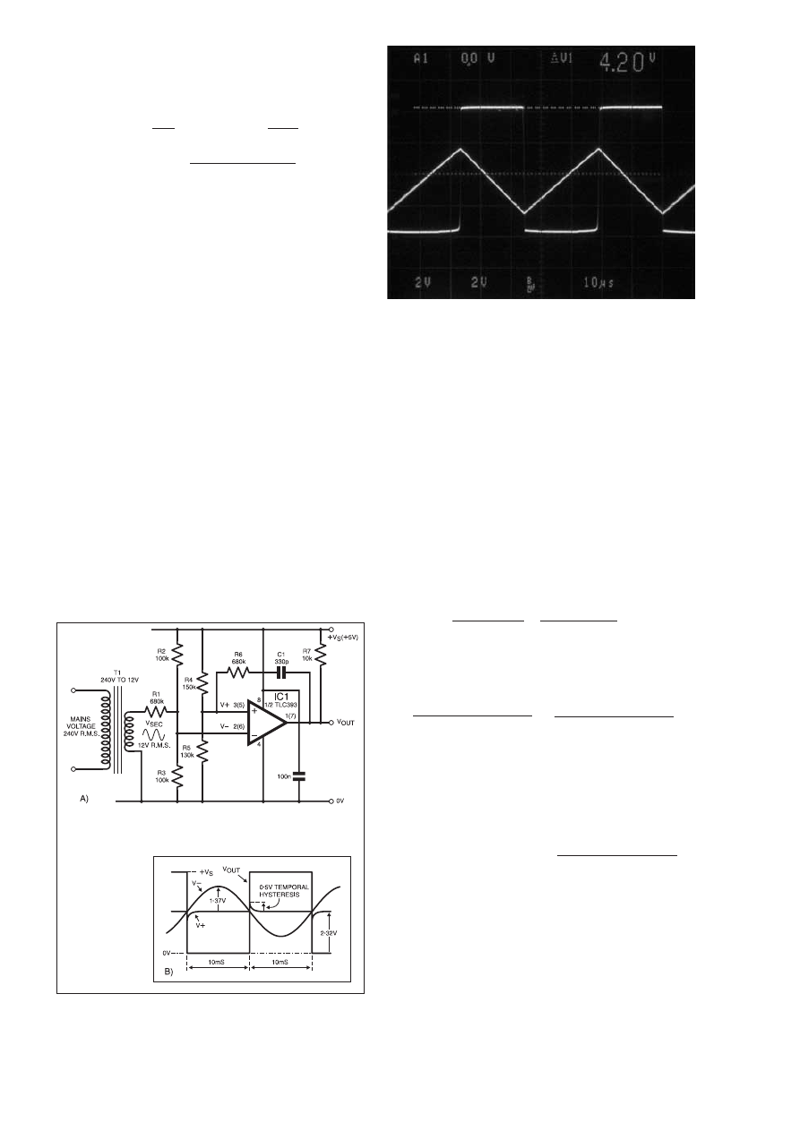
AMPLITUDE AND FREQUENCY
Since the hysteresis V
H
is set by resistors R1 and R2, the magni-
tude of V
OUT(TRI)
can be controlled by varying the ratio of these
resistors. The time constant
t equals (C1 × R3) which, together
with V
H
, determines the pulse widths and frequency of operation:
T1 =
t ×
{
V
H
}
(s); T2 =
t ×
{
V
H
}
(s);
V
SAT+
–V
SAT–
and Frequency f =
(V
SAT+
) × (–V
SAT–
)
(Hz)
V
H
× (V
SAT+
–V
SAT–
) ×
t
If V
H
, V
SAT+
and V
SAT–
are held constant, the frequency can be
continually adjusted by making R3 a variable resistor, and can be
varied in decade steps by switching in different values of C1.
With R3 = 20k
W and C1 = 1nF, the waveforms produced using a
TL082 dual op.amp are shown in Fig.4.9. The TL082 has very low
input bias current and is specified for operation with supplies up to
±15V. Although reasonably fast, it is not a rail-to-rail device; this
can be seen in Fig.4.9, where V
OUT(SQ)
swings between –3·6V and
+4·2V, resulting in a slight asymmetry in the triangle wave timing.
Notice how linear the triangle wave is: compare it with the “expo-
nential’’ waveform shown in Fig.4.3.
When operating on ±5V supply rails, the TL082 produces a well-
shaped triangle wave at frequencies up to 60kHz. At higher fre-
quencies, the triangle peaks start to look “rounded’’ and the square
wave edges become “sloped’’ due to slew rate limitations.
ZERO-CROSSING DETECTOR
In the circuits we have examined so far, the Schmitt trigger has
been used in a “self-contained’’ fashion to generate an output wave-
form. However, some of the most useful applications for the
Schmitt exploit its ability to convert an analogue signal (often slow-
ly changing or poorly shaped) into a digital signal with well-defined
amplitude and rapid transition times.
In this capacity, the Schmitt forms an ideal interface between
sensors and digital systems, two examples of which will be
described shortly. First, though, we shall see how the Schmitt is
used as a zero-crossing detector.
In certain applications, particularly in commercial and industrial
power systems, it is necessary to detect when the sinusoidal mains
voltage waveform crosses through zero. This “zero-crossing’’ point
can be used to trigger power devices such as thyristors, where it is
useful in minimising the electromagnetic interference generated
when the devices switch on and off.
There are many ways of detecting the mains zero-crossing point;
the circuit in Fig.4.10a is just one incarnation of a zero-crossing
detector which uses a transformer, T1, to provide a mains reference
signal. In practice, the circuit would probably be arranged differ-
ently to allow transformer T1 to provide power to a load. However,
as it stands, the circuit can easily be breadboarded for experimental
purposes, and provides a good example of temporal hysteresis
which was introduced in Part Two.
TRANSFORMER
SECONDARY VOLTAGE
Transformer T1 in Fig.4.10a has a root mean square (r.m.s.)
secondary voltage of V
SEC(RMS)
of 12V (transformers with different
secondary voltages could be used with appropriate circuit modifi-
cations). Therefore, the peak secondary voltage is V
SEC(PEAK)
=
±
Ö2 × 12V, or ±17V. Since T1 is effectively “off load’’, we must
assume that V
PEAK
could be a maximum of ±20V.
Since comparator IC1 is powered by a single +5V rail, resistors
R1, R2 and R3 must be selected to ensure the voltage, V–, at the
comparator’s inverting input remains within its common mode
range, which for the TLC393 is 0V to +4V. Using the superposition
theorem, the voltage at the inverting input can be found:
Inverting Input Voltage,
V– =
V
SEC
× (R2//R3)
+
(+V
S
) × (R1//R3)
(volts)
R1 + (R2//R3) R2 + (R1//R3)
where // means “in parallel with’’.
Clearly, since +V
S
is positive, V– will be a maximum when V
SEC
is at its maximum positive value, namely +20V. With R1 = 680k
W,
R2 = 100k
W, and R3 = 100kW, we find that:
V–(max) =
20 × (100k
W//100kW)
+
5 × (680k
W//100kW)
680k
W + (100kW//100kW) 100kW + (680kW//100kW)
= 1·37 + 2·33 = 3·7V
Therefore, provided V
SEC(PEAK)
does not exceed 20V and +V
S
is
regulated to +5V, V– will remain within the 0V to 4V common
mode input voltage range.
Now, we require the comparator to trip each time the mains sinu-
soid crosses the zero point. Provided T1’s primary and secondary
voltages are in phase, this will coincide with the secondary voltage
crossing zero, i.e., when V
SEC
= 0. Substituting this value in the
expression for V–, we see that:
V– at zero-crossing point = 0 +
5 × (680
W//100kW)
100k
W + (680kW//100kW)
= 0 + 2·33 = 2·33V.
Therefore, by selecting resistors R4 and R5 to make the non-
inverting input voltage, V+, equal to 2·33V also, the comparator
will trip each time the mains signal crosses zero. With R4 = 150k
W
and R5 = 130k
W, the quiescent value of V+ is 2·32V.
Resistor R6 and capacitor C1 provide around 0·5V of temporal
hysteresis; this decays to zero after about 1ms as shown by the cir-
cuit waveform diagram in Fig.4.10b. The amount of this “transient’’
hysteresis can be increased by reducing R6 and/or increasing C1 if
there is excessive noise on V
SEC
.
Everyday Practical Electronics, February 2001
143
Fig.4.9. Function Generator Waveforms. Pulse waveform is
V
OUT(SQ)
(2V/div.). Triangular waveform is V
OUT(TR1)
(2V/div.).
Timebase: 10
ms/div.
Fig.4.10b
(right). circuit
waveforms for
the Zero-
Crossing
Detector.
Fig.4.10a. Circuit diagram for a Zero-Crossing Detector
using a transformer and an inverting Schmitt trigger.
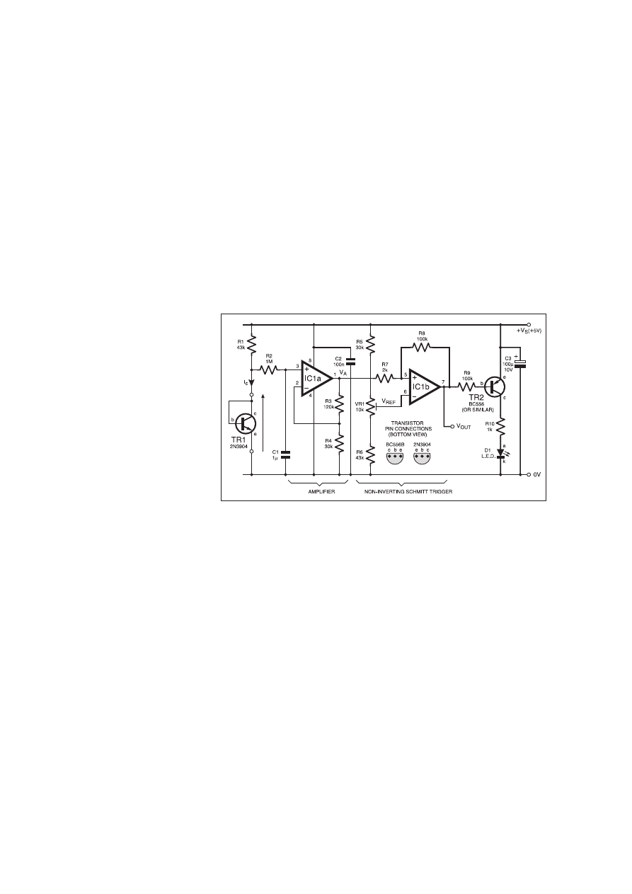
PULL-UP RESISTOR
The TLC393 is a low-power, dual comparator with open drain
output, therefore a pull-up resistor, R7, is needed at the output.
Resistor R7 can be omitted if a comparator like the TLC3702 hav-
ing rail-to-rail output swing is used.
Both the TLC393 and TLC3702 have very low input bias currents
(typically just 5pA) so large resistance values can be used for R1 to
R6. If an alternative device such as the LM393 is used, beware that
the bias currents are much larger (250nA maximum), so it may be
necessary to scale down the resistor values.
Tests on the Zero-Crossing Detector circuit of Fig.4.10a revealed
that the timing error (the time difference between the zero-crossing
points and the rising or falling edge of V
OUT
) was less than 65µs,
which is just 0·33% of the 20ms mains period.
Finally, a word of caution. When experimenting with zero-
crossing detectors, never be tempted to connect the Schmitt
trigger circuitry directly to the mains supply. Not only is this
likely to destroy the low voltage components, but it also bypass-
es the galvanic isolation provided by the transformer, a practice
which can be fatal.
TEMPERATURE DETECTOR
Temperature is probably the most commonly measured physical
parameter, so it is not surprising that it can be measured with many
different types of sensor, such as thermocouples, RTDs (resistance
temperature detectors), thermistors, and so on.
The humble bipolar junction transistor (BJT) makes a surprising-
ly good temperature sensor. For most silicon devices, the base-emit-
ter junction exhibits a reasonably linear tem-
perature coefficient of around –2mV/°C. How
an npn transistor can be combined with an
amplifier and Schmitt trigger to produce an
inexpensive temperature detector is shown in
Fig.4.11.
Transistor TR1 is the sensor. It is “diode-
connected’’ (its base and collector are connect-
ed together), and is biased by resistor R1
which produces a nominal collector current, I
C
,
of around 100µA. Provided the supply voltage,
+V
S
, is held constant, the only changes in base-
emitter voltage, V
BE
, will be due to changes in
TR1’s ambient temperature.
Almost any low-power, small-signal, npn
silicon transistor could be used, but the
2N3904 is well-suited to temperature measure-
ment and is widely used for temperature sens-
ing applications. The combination of resistor
R2 and capacitor C1 form a low-pass filter
which helps to remove any mains pickup or
other low-frequency noise which gets onto the
sensor. (If TR1 is located some distance from
IC1a, it should be connected to the circuit via
a “twisted pair’’ of wires to minimise pickup on the wires
themselves).
Op.amp IC1a should have a wide output swing to accommodate
as much gain as possible. With resistor R3 selected at 120k
9 and
R4 at 30k
9, the amplifier has a gain of five, such that V
A
= 5 × (V
BE
+
∆V
BE
), where V
BE
is the quiescent, room temperature base-emit-
ter voltage, and
∆V
BE
is the change in V
BE
caused by temperature
variations.
THRESHOLD LEVELS
Op.amp IC1b acts as a comparator and forms the Schmitt trigger,
with hysteresis set by resistors R7 and R8; trimmer pot VR1 pro-
vides a variable reference voltage, V
REF
, at the inverting input which
is used to calibrate the detector. The circuit values have been cho-
sen such that the Schmitt’s thresholds correspond to temperature
levels of approximately +25°C and +35°C, although it could be
adapted to trip at other temperatures if required.
Assuming TR1’s temperature coefficient is –2mV/°C, an increase
in temperature of 10°C will cause a change in V
BE
of:
∆V
BE
= 10°C
× (–2mV/°C) = –20mV. The corresponding change in V
A
will be:
∆V
A
= 5 ×
∆V
BE
= 5 × –20mV = –100mV. Therefore, the Schmitt
trigger’s hysteresis must be set to 100mV; provided V
OUT
swings
from 0V to +5V, this is accomplished by selecting R7 = 2k
9 and
R8 = 100k
9.
The values chosen for R5, VR1 and R6 provide a V
REF
range of
around 2·60V to 3·20V. This allows the circuit to be calibrated to
accept any value of V
BE
at 25°C from 540mV to 640mV. The way
this relates to the circuit’s behaviour can be understood by follow-
ing the calibration routine.
CALIBRATING THE DETECTOR
Assuming the particular sample of transistor TR1 in Fig.4.11 has
a room temperature (+25°C) value of V
BE
= 580mV, such that V
A
=
5 × 580mV = 2·9V. Starting with V
REF
at its maximum value such
that V
OUT
is low and the l.e.d. D1 is on, preset VR1 is carefully
adjusted until V
REF
is just slightly less than V
A
, at which point the
comparator trips, V
OUT
goes high and the l.e.d. turns off.
If the temperature now increases slightly, the comparator does
not trip – the hysteresis prevents it from doing so. However, when
the temperature increases to +35°C, the value of V
A
will be low
enough to take IC1b’s non-inverting input voltage below V
REF
: the
comparator trips, V
OUT
goes low and l.e.d. D1 turns on, signaling
that the upper temperature threshold has been reached. Whilst V
OUT
remains low, the l.e.d. stays on until TR1’s temperature has fallen
back down to +25°C, at which point the comparator trips again and
D1 turns off.
When calibrating the detector, the simplest way to raise TR1’s
temperature is to apply heat from a soldering iron; it can quickly be
cooled down again using “freezer spray’’, or by touching it with a
suitable object (e.g. a screwdriver) which has been left in the freez-
er for an hour or so!
The circuit’s accuracy depends largely on the “quality’’ of its cali-
bration. Repeatability (the degree to which the circuit trips at the same
threshold levels over a period of time) depends mainly on the stability
of the hysteresis levels, which in turn depend on V
OUT
and +V
S
.
TRIPPING THE LIGHT FANTASTIC
Like temperature, light is also a commonly measured quantity, and
can be sensed using devices like photodiodes, phototransistors and light
dependent resistors (l.d.r.s). Usually made from Cadmium Sulphide
(CdS), the l.d.r. is strictly a photoconductive cell in which the conduc-
tivity increases in logarithmic fashion as the light intensity increases.
Light dependent resistors are relatively cheap and make ideal
sensors for threshold-type light detectors. An example circuit dia-
gram for a Light Detector with an audio output is shown in Fig.4.12.
The l.d.r. sensor (R2) is connected, together with VR1 and R1, in a
potential divider network at the input to an inverting Schmitt trigger
formed by comparator IC1a. A second comparator, IC1b, is
configured as a “gated’’ astable which drives the piezoelectric
sounder WD1.
Preset potentiometer VR1 is used to set the trigger threshold. The
values chosen for R1 and VR1 depend on the particular light level
that must trip the comparator. For instance, if the circuit is required
to detect a range of relatively high light intensities, then resistor R1
and preset VR1 must be small; on the other hand, operation in dull
conditions will require higher resistance values.
Tests on three samples of the NORP12 revealed that in bright
sunlight the sensor resistance ranged from 40 to 50 ohms. In rela-
tively dark conditions, however, the sensors’ resistance was in the
hundreds of kilohms range.
Few of us are likely to possess a calibrated light source, so the
easiest way to experiment with this circuit is to place the l.d.r. sen-
sor at varying distances from a mains-powered, filament-type 60W
144
Everyday Practical Electronics, February 2001
Fig.4.11. Circuit diagram for a transistor-based Temperature Detector.
V
BE

light bulb in an otherwise darkened room.
Changing the distance between sensor and
bulb effectively varies the light intensity
falling on the sensor.
For example, at just 3cm from the bulb, the
sensor resistance was measured as 104
9; with
the distance increased to 30cm the resistance
increased to 552
9. (Interestingly, the relation-
ship between distance and resistance is fairly
linear, suggesting the l.d.r. could be used in
conjunction with a light source as a crude “dis-
tance meter’’ – albeit only in the dark!)
MID-HYSTERESIS POINT
With resistors R3 and R4 both equal to
10k
9, and provided IC1a has a rail-to-rail out-
put swing, the mid-hysteresis point of the
Schmitt trigger will be +V
S
/2, or 2·5V.
Therefore, if preset VR1 is adjusted such that
R1+VR1 equals the sensor resistance at the
required light level, then the voltage, V
SENSE
, on l.d.r. R2 will also
equal 2·5V and the comparator will trip.
In this circuit (Fig.4.12), resistor R5 must be selected to provide
adequate hysteresis. The degree of hysteresis required will depend
on the operating conditions. One reason for requiring hysteresis is
to eliminate the effects of background light fluctuations which
could otherwise cause the detector to “oscillate’’ about the trip
point.
However, a more important reason for requiring hysteresis in this
kind of experimental set-up is to suppress the effects of mains “rip-
ple’’ in the light bulb intensity. With the values of R1+VR1 set to
470
9, and with the sensor (R2) located 3cm from the 60W bulb, the
r.m.s. component of V
SENSE
was measured as 25mV. This a.c. com-
ponent is caused by the 50Hz mains voltage which effectively
“modulates’’ the light intensity at 100Hz and acts as a kind of
“noise’’. (Why is the modulation frequency twice the mains
frequency?)
An r.m.s. voltage of 25mV corresponds to a peak-to-peak ripple
voltage of 71mV. Therefore, resistor R5 must be selected to provide
hysteresis of at least 71mV such that the ripple voltage on V
SENSE
does not upset the trip point. With R5 = 240k
9, the thresholds are
V
TL
= 2·449V and V
TU
= 2·551V and the hysteresis is V
H
= 102mV.
Reducing R5 will increase the hysteresis if more “noise immunity’’
is required.
GATED OSCILLATOR
When the light intensity is low, the l.d.r. sensor’s resistance is
large compared to R1+VR1, and so V
SENSE
is greater than 2·5V,
causing IC1a’s output to be in negative saturation. Since the
TLC3702 dual comparator is capable of rail-to-rail output swings,
diode D1’s cathode (k) potential will be very near to 0V.
Consequently, D1 is forward biased, effectively “clamping’’ the
voltage on capacitor C2 to around 0·7V. This prevents the astable
from oscillating, and forces IC1b’s output voltage into positive sat-
uration such that there is no voltage across the piezoelectric sounder
WD1.
However, as the l.d.r. sensor (R2) is moved closer to the light
source, its resistance falls and V
SENSE
decreases. When the sensor
resistance is low enough, the detector trips and IC1a’s output goes
high, reverse biasing diode D1. The astable is now free to run, and
the squarewave voltage at IC1b’s output causes WD1 to sound.
RESONANT FREQUENCY
Capacitor C2 and resistor R9 set the astable’s time constant. This
should be chosen to set the operating frequency as close as possible
to the piezoelectric sounder’s resonant frequency. With the compo-
nent values shown in Fig.4.12, the frequency is around 4·4kHz,
quite close to WD1’s resonant frequency of 4·5kHz. If alternative
sounders are used, C2 and R8 should be adjusted, if necessary, to
suit the sounder’s characteristics.
Calibrating the Detector stage is easy. Start with preset VR1 at its
minimum resistance and locate the l.d.r. sensor R2 at the required
distance from the light bulb. Then, slowly adjust VR1 until sounder
WD1 just begins to sound.
As the sensor is moved either side of the threshold point (the pre-
set distance from the bulb), the sounder should turn on and off
“cleanly’’. However, if resistor R5 is removed from the circuit, such
that the comparator no longer has any hysteresis, the sounder will
now produce a “squawking’’ sound when the sensor is moved near
the trip point: this is caused by the mains ripple effectively modu-
lating the astable’s output frequency.
This dramatic effect is a perfect example of how hysteresis can
be used to overcome the problems caused by noise and interference.
In this case, the unwanted signal is the ripple voltage on V
SENSE
. It
oscillates at twice the mains frequency simply because the mains
sinusoid reaches a peak (one positive, one negative) twice each
cycle: each peak in the mains voltage causes a slight increase in the
bulb’s light output, i.e., the light intensity is “modulated’’ at twice
the 50Hz mains frequency.
LOOKING AHEAD
The Light Detector circuit in Fig.4.12 employs not one, but two
Schmitt triggers, each performing a different task. There can be lit-
tle doubt that the Schmitt function is a versatile and essential ele-
ment in analogue systems built using op.amps and comparators.
However, as we shall see in Part Five, the Schmitt trigger finds
many applications in digital systems, where specialised Schmitt
trigger logic gates are available to simplify the design task.
Fig.4.12. Circuit diagram for a Light Detector, with audible output.
145
Everyday Practical Electronics, February 2001
WD1
SUBSCRIPTION ORDER FORM
Annual subscription rates (2001):
6 Months: UK £14.50, Overseas £17.50 (standard air service),
£27 (express airmail)
1 Year: UK £27.50, Overseas £33.50 (standard air service)
£51 (express airmail)
2 Years: UK £50.00, Overseas £62.00 (standard air service)
£97 (express airmail)
To: Everyday Practical Electronics,
Allen House, East Borough, Wimborne, Dorset BH21 1PF
Tel: 01202 881749 Fax: 01202 841692
E-mail: subs@epemag.wimborne.co.uk
Name ..................................................................................................
Address ...............................................................................................
.............................................................................................................
...................................................................Post code .........................
SUBSCRIPTION ORDER FORM
I enclose payment of £........... (cheque/PO in
£ sterling only),
payable to Everyday Practical Electronics
My card number is: .......................................................................................
Signature ........................................................................................................
Card Ex. Date .....................................................Switch Issue No. ................
Subscriptions can only start with the next available issue.
For back numbers see the Back Issues page.
2/01
Please print clearly, and check that you have the number correct
S
SA
AV
VE
E U
UP
P T
TO
O 6
66
6p
p A
AN
N IIS
SS
SU
UE
E

PRACTICAL REMOTE CONTROL PROJECTS
Owen Bishop
Provides a wealth of circuits and circuit modules for use
in remote control systems of all kinds; ultrasonic, infra-
red, optical fibre, cable and radio. There are instructions
for building fourteen novel and practical remote control
projects. But this is not all, as each of these projects
provides a model for building dozens of other related cir-
cuits by simply modifying parts of the design slightly to
suit your own requirements. This book tells you how.
Also included are techniques for connecting a PC to a
remote control system, the use of a microcontroller in
remote control, as exemplified by the BASIC Stamp, and
the application of ready-made type-approved 418MHz
radio transmitter and receiver modules to remote control
systems.
PRACTICAL ELECTRONIC MODEL RAILWAY
PROJECTS
R. A. Penfold
The aim of this book is to provide the model railway
enthusiast with a number of useful but reasonably sim-
ple projects that are easily constructed from readily
available components. Stripboard layouts and wiring
diagrams are provided for each project. The projects
covered include: constant voltage controller; pulsed con-
troller; pushbutton pulsed controller; pulsed controller
with simulated inertia, momentum and braking;
automatic signals; steam whistle sound effect; two-tone
horn sound effect; automatic two-tone horn effect;
automatic chuffer.
The final chapter covers the increasingly popular sub-
ject of using a computer to control a model railway lay-
out, including circuits for computer-based controllers
and signalling systems.
A PRACTICAL INTRODUCTION TO SURFACE
MOUNT DEVICES
Bill Mooney
This book takes you from the simplest possible starting
point to a high level of competence in handworking with
surface mount devices (SMD’s). The wider subject of SM
technology is also introduced, so giving a feeling for its
depth and fascination.
Subjects such as p.c.b. design, chip control, soldering
techniques and specialist tools for SM are fully
explained and developed as the book progresses. Some
useful constructional projects are also included.
Whilst the book is mainly intended as an introduction
it is also an invaluable reference book, and the browser
should find it engrossing.
146
Everyday Practical Electronics, February 2001
FAULT-FINDING ELECTRONIC PROJECTS
R. A. Penfold
Starting with mechanical faults such as dry joints, short-circuits
etc, coverage includes linear circuits, using a meter to make
voltage checks, signal tracing techniques and fault finding on
logic circuits. The final chapter covers ways of testing a wide
range of electronic components, such as resistors, capacitors,
operational amplifiers, diodes, transistors, SCRs and triacs,
with the aid of only a limited amount of test equipment.
The construction and use of a Tristate Continuity Tester, a
Signal Tracer, a Logic Probe and a CMOS Tester are also
included.
TEST EQUIPMENT CONSTRUCTION
R. A. Penfold
This book describes in detail how to construct some simple and
inexpensive but extremely useful, pieces of test equipment.
Stripboard layouts are provided for all designs, together with
wiring diagrams where appropriate, plus notes on construction
and use.
The following designs are included:-
AF Generator, Capacitance Meter, Test Bench Amplifier, AF
Frequency Meter, Audio Mullivoltmeter, Analogue Probe, High
Resistance Voltmeter, CMOS Probe, Transistor Tester, TTL
Probe. The designs are suitable for both newcomers and more
experienced hobbyists.
HOW TO DESIGN AND MAKE YOUR OWN P.C.B.s
R. A. Penfold
Deals with the simple methods of copying printed circuit board
designs from magazines and books, and covers all aspects of
simple p.c.b. construction including photographic methods and
designing your own p.c.b.s.
ELECTRONIC PROJECT BUILDING FOR BEGINNERS
R. A. Penfold
This book is for complete beginners to electronic project
building. It provides a complete introduction to the practical
side of this fascinating hobby, including the following topics:
Component identification, and buying the right parts;
Resistor colour codes, capacitor value markings, etc;
Advice on buying the right tools for the job; Soldering, with
advice on how to produce good joints and avoid “dry’’ joints;
Making easy work of the hard wiring; Construction meth-
ods, including stripboard, custom printed circuit boards,
plain matrix board, surface mount boards and wire-wrap-
ping; Finishing off, and adding panel labels; Getting
“problem” projects to work, including simple methods of
fault-finding; In fact everything you need to know in order to
get started in this absorbing and creative hobby.
DIRECT BOOK SERVICE
NEW SOFTBACK
EDITION
THE INVENTOR OF STEREO – THE LIFE AND
WORKS OF ALAN DOWER BLUMLEIN
Robert Charles Alexander
This book is the definitive study of the life and works
of one of Britain’s most important inventors who, due
to a cruel set of circumstances, has all but been over-
looked by history.
Alan Dower Blumlein led an extraordinary life in
which his inventive output rate easily surpassed that
of Edison, but whose early death during the darkest
days of World War Two led to a shroud of secrecy
which has covered his life and achievements ever
since.
His 1931 Patent for a Binaural Recording System
was so revolutionary that most of his contemporaries
regarded it as more than 20 years ahead of its time.
Even years after his death, the full magnitude of its
detail had not been fully utilized. Among his 128
patents are the principal electronic circuits critical to
the development of the world’s first elecronic television
system. During his short working life, Blumlein pro-
duced patent after patent breaking entirely new
ground in electronic and audio engineering.
During the Second World War, Alan Blumlein was
deeply engaged in the very secret work of radar devel-
opment and contributed enormously to the system
eventually to become ‘H2S’ – blind-bombing radar.
Tragically, during an experimental H2S flight in June
1942, the Halifax bomber in which Blumlein and sev-
eral colleagues were flying, crashed and all aboard
were killed. He was just days short of his thirty-ninth
birthday.
Only £14.99
The books listed have been
selected by
Everyday Practical
Electronics
editorial staff as
being of special interest to
everyone involved in electron-
ics and computing. They are
supplied by mail order to your
door. Full ordering details are
given on the last book page.
Note our UK postage costs just
£2.00 no matter how many
books you order!
FOR A FURTHER SELECTION
OF BOOKS SEE THE NEXT
TWO ISSUES OF EPE.
project construction
420 pages
£14.99
Order code NE32
160 pages
£5.99
Order code BP413
120 pages
£4.99
Order code BP411
151 pages
£4.99
Order code BP384
136 pages
£4.99
Order code BP391
104 pages
£3.99
Order code BP248
radio / tv
video
TEACH-IN No. 7.
ANALOGUE AND DIGITAL ELECTRONICS COURSE
(published by
Everyday Practical Electronics)
Alan Winstanley and Keith Dye B.Eng(Tech)AMIEE
This highly acclaimed
EPE Teach-In series, which included
the construction and use of the Mini Lab and Micro Lab test
and development units, has been put together in book
form.
An interesting and thorough tutorial series aimed
specifically at the novice or complete beginner in electron-
ics. The series is designed to support those undertaking
either GCSE Electronics or GCE Advanced Levels, and
starts with fundamental principles.
If you are taking electronics or technology at school or
college, this book is for you. If you just want to learn the
basics of electronics or technology you must make sure
you see it.
Teach-In No. 7 will be invaluable if you are con-
sidering a career in electronics or even if you are already
training in one. The Mini Lab and software enable the
construction and testing of both demonstration and devel-
opment circuits. These learning aids bring electronics to life
in an enjoyable and interesting way: you will both see and
hear the electron in action! The Micro Lab microprocessor
add-on system will appeal to higher level students and
those developing microprocessor projects.
TEACH-IN 2000 plus FREE software
John Becker
The
Teach-In 2000 series is now available on CD-ROM,
see advert elsewhere in this issue.
ELECTRONIC PROJECTS FOR VIDEO ENTHUSIASTS
R. A. Penfold
This book provides a number of practical designs for
video accessories that will help you get the best results
from your camcorder and VCR. All the projects use
inexpensive components that are readily available, and
they are easy to construct. Full construction details are
provided, including stripboard layouts and wiring dia-
grams. Where appropriate, simple setting up procedures
are described in detail; no test equipment is needed.
The projects covered in this book include: Four channel
audio mixer, Four channel stereo mixer, Dynamic noise
limiter (DNL), Automatic audio fader, Video faders, Video
wipers, Video crispener, Mains power supply unit.
SETTING UP AN AMATEUR RADIO STATION
I. D. Poole
The aim of this book is to give guidance on the decisions
which have to be made when setting up any amateur
radio or short wave listening station. Often the experience
which is needed is learned by one’s mistakes, however,
this can be expensive. To help overcome this, guidance is
given on many aspects of setting up and running an effi-
cient station. It then proceeds to the steps that need to be
taken in gaining a full transmitting licence.
Topics covered include: The equipment that is needed;
Setting up the shack; Which aerials to use; Methods of
construction; Preparing for the licence.
An essential addition to the library of all those taking
their first steps in amateur radio.
EXPERIMENTAL ANTENNA TOPICS
H. C. Wright
Although nearly a century has passed since Marconi’s first
demonstration or radio communication, there is still
research and experiment to be carried out in the field of
antenna design and behaviour.
The aim of the experimenter will be to make a measure-
ment or confirm a principle, and this can be done with
relatively fragile, short-life apparatus. Because of this,
devices described in this book make liberal use of card-
board, cooking foil, plastic bottles, cat food tins, etc. These
materials are, in general, cheap to obtain and easily worked
with simple tools, encouraging the trial-and-error philosophy
which leads to innovation and discovery.
Although primarily a practical book with text closely
supported by diagrams, some formulae which can be used
by straightforward substitution and some simple graphs
have also been included.
25 SIMPLE INDOOR AND WINDOW AERIALS
E. M. Noll
Many people live in flats and apartments or other types of
accommodation where outdoor aerials are prohibited, or a
lack of garden space etc. prevents aerials from being
erected.This does not mean you have to forgo shortwave-lis-
tening, for even a 20-foot length of wire stretched out along
the skirting board of a room can produce acceptable results.
However, with some additional effort and experimentation
one may well be able to improve performance further.
This concise book tells the story, and shows the reader
how to construct and use 25 indoor and window aerials that
the author has proven to be sure performers. Much infor-
mation is also given on shortwave bands, aerial directivity,
time zones, dimensions etc.
66 pages
£3.99
Order code BP121
135 pages
£4.95
Order code BP392
109 pages
£4.95
Order code BP356
86 pages
£3.95
Order code BP300
152 pages
£3.95
Order code TI7
72 pages
£3.50
Order code BP278
50 pages
£1.75
Order code BP136
NEW

Everyday Practical Electronics, February 2001
147
POSTAGE
You
only
pay
£2.00
per order
(UK postage)
NO MATTER HOW
MANY BOOKS
YOU ORDER
Overseas Readers see
ORDERING DETAILS on the
next page for overseas
postage prices
VALVE & TRANSISTOR AUDIO AMPLIFIERS
John Linsley Hood
This is John Linsley Hood’s greatest work yet, describ-
ing the milestones that have marked the development of
audio amplifiers since the earliest days to the latest sys-
tems. Including classic amps with valves at their heart
and exciting new designs using the latest components,
this book is the complete world guide to audio amp
design.
Contents: Active components; Valves or vacuum
tubes; Solid-state devices; Passive components;
Inductors and transformers; Capacitors, Resistors,
Switches and electrical contacts; Voltage amplifier
stages using valves; Valve audio amplifier layouts;
Negative feedback; Valve operated power amplifiers;
Solid state voltage amplifiers; Early solid-state audio
amplifiers; Contemporary power amplifier designs;
Preamplifiers; Power supplies (PSUs); Index.
AUDIO AMPLIFIER PROJECTS
R. A. Penfold
A wide range of useful audio amplifier projects, each
project features a circuit diagram, an explanation of the
circuit operation and a stripboard layout diagram. All
constructional details are provided along with a shop-
ping list of components, and none of the designs
requires the use of any test equipment in order to set up
properly. All the projects are designed for straightforward
assembly on simple circuit boards.
Circuits include: High impedance mic preamp, Low
impedance mic preamp, Crystal mic preamp, Guitar and
GP preamplifier, Scratch and rumble filter, RIAA
preamplifier, Tape preamplifier, Audio limiter, Bass and tre-
ble tone controls, Loudness filter, Loudness control,
Simple graphic equaliser, Basic audio mixer, Small
(300mW) audio power amp, 6 watt audio power amp,
20/32 watt power amp and power supply, Dynamic noise
limiter.
A must for audio enthusiasts with more sense than
money!
MAKING MUSIC WITH DIGITAL AUDIO
Ian Waugh
In this practical and clearly written book, Ian Waugh
explains all aspects of the subject from digital audio basics
to putting together a system to suit your own music
requirements. Using the minimum of technical language,
the book explains exactly what you need to know about:
Sound and digital audio, Basic digital recording principles,
Sample rates and resolutions, Consumer sound cards and
dedicated digital audio cards.
On a practical level you will learn about: sample editing,
digital multi-tracking, digital FX processing, integrating
MIDI and digital audio, using sample CDs, mastering to
DAT and direct to CD, digital audio and Multimedia.
This book is for every musician who wants to be a part
of the most important development in music since the
invention of the gramophone. It’s affordable, it’s flexible, it’s
powerful and it’s here now! It’s digital and it’s the future of
music making.
250 pages
£19.99
Order code NE24
116 pages
£9.95
Order code PC113
256 pages
£14.95
Order code PC114
Audio and Music
Bebop To The
Boolean Boogie
By Clive (call me Max) Maxfield
ORDER CODE BEB1
£24.95
An Unconventional Guide to Electronics
Fundamentals, Components and Processes
The Foreword by Pete Waddell, Editor,
Printed Circuit Design reads:
“Personally, I think that the title of this tome alone (hmmm, a movie?)
should provide some input as to what you can expect. But, for those who
require a bit more: be forewarned, dear reader, you will probably learn
far more than you could hope to expect from
Bebop to the Boolean
Boogie, just because of the unique approach Max has to technical mate-
rial. The author will guide you from the basics through a minefield of
potentially boring theoretical mish-mash, to a Nirvana of understanding.
You will not suffer that fate famil-
iar to every reader: re-reading
paragraphs over and over won-
dering what in the world the
author was trying to say. For a
limey, Max shoots amazingly well
and from the hip, but in a way that
will keep you interested and
amused. If you are not vigilant,
you may not only learn some-
thing, but you may even enjoy the
process. The only further advice I
can give is to ‘expect the unex-
pected’.’’
This book gives the “big picture’’
of digital electronics. This indepth,
highly readable, up-to-the-minute
guide shows you how electronic
devices work and how they’re
made. You’ll discover how transis-
tors operate, how printed circuit
boards are fabricated, and what the innards of memory ICs look like. You’ll
also gain a working knowledge of Boolean Algebra and Karnaugh Maps,
and understand what Reed-Muller logic is and how it’s used. And there’s
much, MUCH more (including a recipe for a truly great seafood gumbo!).
Hundreds of carefully drawn illustrations clearly show the important
points of each topic. The author’s tongue-in-cheek British humor makes
it a delight to read, but this is a REAL technical book, extremely detailed
and accurate. A great reference for your own shelf, and also an ideal gift
for a friend or family member who wants to understand what it is you do
all day. . . .
By importing these books ourselves we have managed to
make them available at an exceptional price.
Bebop Bytes Back
By Clive “Max’’ Maxfield and
Alvin Brown
ORDER CODE BEB2
£29.95
An Unconventional Guide To Computers
Plus FREE CD-ROM which includes: Fully Functional
Internet-Ready Virtual Computer with Interactive Labs
The Foreword by Lee Felsenstein reads:
“1. The more time you spend with this book and its accompanying
CD-ROM, the more you’ll get out of it. Skimming through it won’t
take you where you want to go. Paying serious attention, on the
other hand, will teach you more about computers than you can
imagine. (You might also see a few beautiful sunrises.)
2. The labs work on two levels: on and under the surface. When
you’re performing the labs
you’ll need to look for patterns
that build up from individual
events.
3. When you’re done, you
won’t look any different. You
won’t get a trophy or a certifi-
cate to hang on your wall.
You’ll have some knowledge,
and some skill, and you’ll be
ready to find more knowledge
and develop more skill. Much
of this will be recognisable
only to someone who has the
same knowledge and skill.’’
This follow-on to
Bebop to
the Boolean Boogie is a multi-
media extravaganza of infor-
mation about how computers
work. It picks up where
“Bebop I’’ left off, guiding you
through the fascinating world of computer design . . . and you’ll have
a few chuckles, if not belly laughs, along the way. In addition to over
200 megabytes of mega-cool multimedia, the accompanying CD-
ROM (for Windows 95 machines only) contains a virtual
microcomputer, simulating the motherboard and standard computer
peripherals in an extremely realistic manner. In addition to a wealth
of technical information, myriad nuggets of trivia, and hundreds of
carefully drawn illustrations, the book contains a set of lab experi-
ments for the virtual microcomputer that let you recreate the
experiences of early computer pioneers.
If you’re the slightest bit interested in the inner workings of
computers, then don’t dare to miss this one!
TWO EXCITING BOOKS
Specially imported by
EPE

AN INTRODUCTION TO PIC MICROCONTROLLERS
Robert Penfold
Designing your own PIC based projects may seem a
daunting task, but it is really not too difficult providing you
have some previous experience of electronics.
The PIC processors have plenty of useful features, but
they are still reasonably simple and straightforward to
use. This book should contain everything you need to
know.
Topics covered include: the PIC register set; numbering
systems; bitwise operations and rotation; the PIC instruc-
tion set; using interrupts; using the analogue to digital
converter; clock circuits; using the real time clock counter
(RTCC); using subroutines; driving seven segment dis-
plays.
PRACTICAL OSCILLATOR CIRCUITS
A. Flind
Extensive coverage is given to circuits using capacitors
and resistors to control frequency. Designs using CMOS,
timer i.c.s and op.amps are all described in detail, with a
special chapter on ``waveform generator’’ i.c.s. Reliable
“white’’ and “pink’’ noise generator circuits are also includ-
ed.
Various circuits using inductors and capacitors are cov-
ered, with emphasis on stable low frequency generation.
Some of these are amazingly simple, but are still very
useful signal sources.
Crystal oscillators have their own chapter. Many of the
circuits shown are readily available special i.c.s for
simplicity and reliability, and offer several output frequen-
cies. Finally, complete constructional details are given for
an audio sinewave generator.
PRACTICAL ELECTRONIC CONTROL PROJECTS
Owen Bishop
Explains electronic control theory in simple, non-mathe-
matical terms and is illustrated by 30 practical designs
suitable for the student or hobbyist to build. Shows how to
use sensors as input to the control system, and how to
provide output to lamps, heaters, solenoids, relays and
motors.
Computer based control is explained by practical exam-
ples that can be run on a PC. For stand-alone systems,
the projects use microcontrollers, such as the inexpensive
and easy-to-use Stamp BASIC microcontroller.
PRACTICAL ELECTRONICS HANDBOOK –
Fifth Edition. Ian Sinclair
Contains all of the everyday information that anyone
working in electronics will need.
It provides a practical and comprehensive collection of
circuits, rules of thumb and design data for professional
engineers, students and enthusaists, and therefore
enough background to allow the understanding and
development of a range of basic circuits.
Contents:
Passive components, Active discrete
components, Circuits, Linear I.C.s, Energy conversion com-
ponents, Digital I.C.s, Microprocessors and microprocessor
systems, Transferring digital data, Digital-analogue conver-
sions, Computer aids in electronics, Hardware components
and practical work, Microcontrollers and PLCs, Digital broad-
casting, Electronic security.
COIL DESIGN AND CONSTRUCTIONAL MANUAL
B. B. Babani
A complete book for the home constructor on “how to
make’’ RF, IF, audio and power coils, chokes and trans-
formers. Practically every possible type is discussed and
calculations necessary are given and explained in detail.
Although this book is now twenty years old, with the
exception of toroids and pulse transformers little has
changed in coil design since it was written.
OPTOELECTRONICS CIRCUITS MANUAL
R. M. Marston
A useful single-volume guide to the optoelectronics
device user, specifically aimed at the practical design
engineer, technician, and the experimenter, as well as
the electronics student and amateur. It deals with the
subject in an easy-to-read, down-to-earth, and non-
mathematical yet comprehensive manner, explaining
the basic principles and characteristics of the best
known devices, and presenting the reader with many
practical applications and over 200 circuits. Most of the
i.c.s and other devices used are inexpensive and read-
ily available types, with universally recognised type
numbers.
OPERATIONAL AMPLIFIER USER’S HANDBOOK
R. A. Penfold
The first part of this book covers standard operational amplif-
er based “building blocks’’ (integrator, precision rectifier,
function generator, amplifiers, etc), and considers the ways in
which modern devices can be used to give superior perfor-
mance in each one. The second part describes a number of
practical circuits that exploit modern operational amplifiers,
such as high slew-rate, ultra low noise, and low input offset
devices. The projects include: Low noise tape preamplifier,
low noise RIAA preamplifier, audio power amplifiers, d.c.
power controllers, opto-isolator audio link, audio millivolt
meter, temperature monitor, low distortion audio signal
generator, simple video fader, and many more.
A BEGINNERS GUIDE TO CMOS DIGITAL ICs
R. A. Penfold
Getting started with logic circuits can be difficult, since many
of the fundamental concepts of digital design tend to seem
rather abstract, and remote from obviously useful applica-
tions. This book covers the basic theory of digital electronics
and the use of CMOS integrated circuits, but does not lose
sight of the fact that digital electronics has numerous “real
world’’ applications.
The topics covered in this book include: the basic concepts
of logic circuits; the functions of gates, inverters and other
logic “building blocks’’; CMOS logic i.c. characteristics, and
their advantages in practical circuit design; oscillators and
monostables (timers); flip/flops, binary dividers and binary
counters; decade counters and display drivers.
148
Everyday Practical Electronics, February 2001
INTRODUCTION TO DIGITAL AUDIO
(Second Edition) Ian Sinclair
The compact disc (CD) was the first device to bring digital
audio methods into the home.
This development has involved methods and circuits
that are totally alien to the technician or keen amateur
who has previously worked with audio circuits. The princi-
ples and practices of digital audio owe little or nothing to
the traditional linear circuits of the past, and are much
more comprehensible to today’s computer engineer than
the older generation of audio engineers.
This book is intended to bridge the gap of understand-
ing for the technician and enthusiast. The principles and
methods are explained, but the mathematical background
and theory is avoided, other than to state the end product.
PROJECTS FOR THE ELECTRIC GUITAR
J. Chatwin
This book is for anyone interested in the electric gui-
tar. It explains how the electronic functions of the
instrument work together, and includes information on
the various pickups and transducers that can be fitted.
There are complete circuit diagrams for the major
types of instrument, as well as a selection of wiring
modifications and pickup switching circuits. These can
be used to help you create your own custom wiring.
Along with the electric guitar, sections are also
included relating to acoustic instruments. The function
of specialised piezoelectric pickups is explained and
there are detailed instructions on how to make your own
contact and bridge transducers. The projects range
from simple preamps and tone boosters, to complete
active controls and equaliser units.
VALVE AMPLIFIERS
Second Edition. Morgan Jones
This book allows those with a limited knowledge of the field
to understand both the theory and practice of valve audio
amplifier design, such that they can analyse and modify cir-
cuits, and build or restore an amplifier. Design principles and
construction techniques are provided so readers can devise
and build from scratch, designs that actually work.
The second edition of this popular book builds on its main
strength – exploring and illustrating theory with practical
applications. Numerous new sections include: output trans-
former problems; heater regulators; phase splitter analysis;
and component technology. In addition to the numerous
amplifier and preamplifier circuits, three major new designs
are included: a low-noise single-ended LP stage, and a pair
of high voltage amplifiers for driving electrostatic transduc-
ers directly – one for headphones, one for loudspeakers.
VALVE RADIO AND AUDIO REPAIR HANDBOOK
Chas Miller
This book is not only an essential read for every profes-
sional working with antique radio and gramophone
equipment, but also dealers, collectors and valve tech-
nology enthusiasts the world over. The emphasis is firm-
ly on the practicalities of repairing and restoring, so
technical content is kept to a minimum, and always
explained in a way that can be followed by readers with
no background in electronics. Those who have a good
grounding in electronics, but wish to learn more about
the practical aspects, will benefit from the emphasis
given to hands-on repair work, covering mechanical as
well as electrical aspects of servicing. Repair techniques
are also illustrated throughout.
A large reference section provides a range of infor-
mation compiled from many contemporary sources, and
includes specialist dealers for valves, components and
complete receivers.
LOUDSPEAKERS FOR MUSICIANS
Vivan Capel
This book contains all that a working musician needs to
know about loudspeakers; the different types, how they
work, the most suitable for different instruments, for
cabaret work, and for vocals. It gives tips on constructing
cabinets, wiring up, when and where to use wadding,
and when not to, what fittings are available, finishing,
how to ensure they travel well, how to connect multi-
speaker arrays and much more.
Ten practical enclosure designs with plans and
comments are given in the last chapter, but by the time
you’ve read that far you should be able to design your
own!
circuits and design
audio and music
166 pages
£5.99
Order code BP394
133 pages
£4.99
Order code BP393
440 pages
£14.99
Order code NE21
96 pages
£3.99
Order code 160
182 pages
£14.99
Order code NE14
119 pages
£4.95
Order code BP333
120 pages
£4.95
Order code BP335
92 pages
£4.95
Order code BP358
488 pages
£24.99
Order code NE33
288 pages
£19.99
Order code NE34
164 pages
£4.99
Order code BP297
BOOK ORDERING DETAILS
Our postage price is the same no matter how many books you order, just add £2.00 to your
total order for postage and packing (overseas readers add £4 for countries in the EEC, or add
£7 for all countries outside the EEC, surface mail postage) and send a PO, cheque, international
money order (£ sterling only) made payable to Direct Book Service or credit card details, Visa,
Mastercard or Switch – minimum card order is £5 – to:
DIRECT BOOK SERVICE, ALLEN HOUSE, EAST BOROUGH, WIMBORNE, DORSET BH21 1PF
Books are normally sent within seven days of receipt of order, but please allow 28 days for
delivery (more for overseas orders).
Please check price and availability (see latest issue of
Everyday Practical Electronics) before ordering from old lists.
For a further selection of books see the next two issues of
EPE.
DIRECT BOOK SERVICE IS A DIVISION OF WIMBORNE PUBLISHING LTD.
Tel 01202 881749 Fax 01202 841692.
E-mail:dbs@epemag.wimborne.co.uk
198 pages
£5.99
Order code BP377
128 pages
£7.95
Order code PC102
BOOK ORDER FORM
Full name: ...............................................................................................................................................
Address: ..................................................................................................................................................
.................................................................................................................................................................
.................................................................................................................................................................
.............................................. Post code: ........................... Telephone No: .............................................
Signature: ................................................................................................................................................
I enclose cheque/PO payable to DIRECT BOOK SERVICE for £ ...................................................
Please charge my Visa/Mastercard/Switch £ ............................. Card expiry date .........................
Card Number .......................................................................................... Switch Issue No .....................
Please send book order codes:
.................................................................................................................................................................
Please continue on separate sheet of paper if necessary
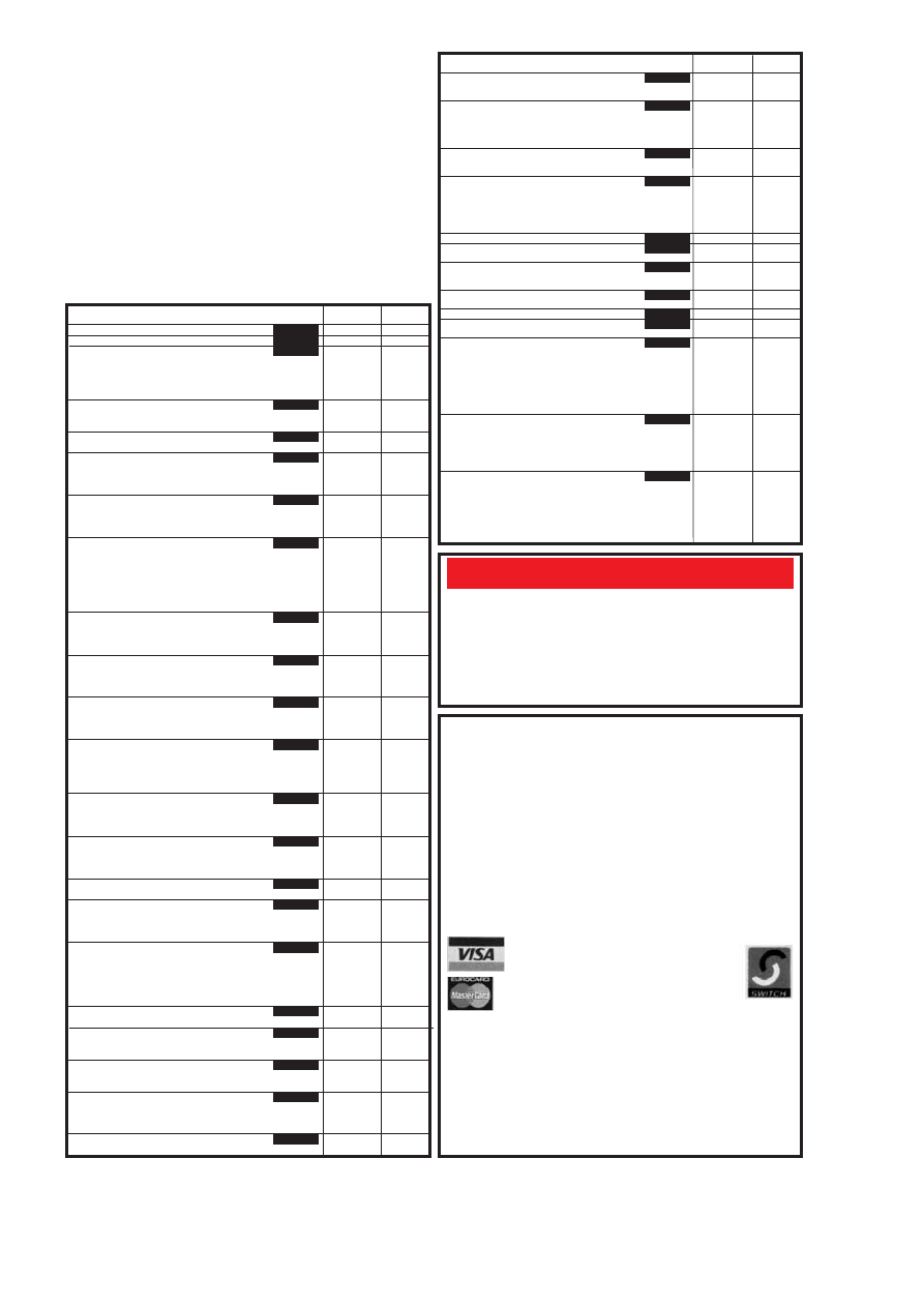
PROJECT TITLE
oRC-Meter
oDice Lott
EPE Mood Changer
(AT89C2051/1051 Programmer
Main Board
Test Board
oReaction Timer
Software only
oPIC16x84 Toolkit
oGreenhouse Computer
Control Board
Float Charger
Lightbulb Saver
Personal Stereo Amplifier
(Multi-project PCB)
oGreenhouse Radio Link
oPIC Altimeter
Voice Processor
IR Remote Control
–Transmitter
– Receiver
oPIC Tape Measure
Electronic Thermostat – T-Stat
PhizzyB
A – PCB B – CD-ROM C – Prog. Microcontroller
15-Way IR Remote Control
Switch Matrix
15-Way Rec/Decoder
Damp Stat
Handheld Function Generator
oFading Christmas Lights
PhizzyB I/O Board (4-section)
Twinkle Twinkle Reaction Game
oEPE Mind PICkler
PhizzyB I/O Board (4-section)
Alternative Courtesy Light Controller
Light Alarm
oWireless Monitoring System Transmitter
Receiver
oPIC MIDI Sustain Pedal
Software only
oWireless Monitoring System-2
F.M. Trans/Rec Adaptors
oTime and Date Generator
Auto Cupboard Light
Smoke Absorber
Ironing Board Saver
Voice Record/Playback Module
Mechanical Radio (pair)
oVersatile Event Counter
PIC Toolkit Mk2
A.M./F.M. Radio Remote Control
Transmitter
Receiver
oMusical Sundial
PC Audio Frequency Meter
oEPE Mood PICker
12V Battery Tester
Intruder Deterrent
L.E.D. Stroboscope (Multi-project PCB)
Ultrasonic Puncture Finder
o8-Channel Analogue Data Logger
Buffer Amplifier (Oscillators Pt 2)
Magnetic Field Detective
Sound Activated Switch
Freezer Alarm (Multi-project PCB)
Child Guard
Variable Dual Power Supply
Micro Power Supply
oInterior Lamp Delay
Mains Cable Locator (Multi-project PCB)
Vibralarm
Demister One-Shot
oGinormous Stopwatch – Part 1
oGinormous Stopwatch – Part 2
Giant Display
Serial Port Converter
Loft Guard
Scratch Blanker
Flashing Snowman (Multi-project PCB)
Everyday Practical Electronics, February 2001
149
Printed circuit boards for most recent
EPE constructional projects are available from
the PCB Service, see list. These are fabricated in glass fibre, and are fully drilled and
roller tinned. All prices include VAT and postage and packing. Add £1 per board for
airmail outside of Europe. Remittances should be sent to The PCB Service,
Everyday Practical Electronics, Allen House, East Borough, Wimborne, Dorset
BH21 1PF. Tel: 01202 881749; Fax 01202 841692; E-mail: orders@epemag.wim-
borne.co.uk. Cheques should be crossed and made payable to
Everyday Practical
Electronics (Payment in £ sterling only).
NOTE: While 95% of our boards are held in stock and are dispatched within
seven days of receipt of order, please allow a maximum of 28 days for delivery
– overseas readers allow extra if ordered by surface mail.
Back numbers or photostats of articles are available if required – see the
Back
Issues page for details.
Please check price and availability in the latest issue.
Boards can only be supplied on a payment with order basis.
Software programs for
EPE projects marked with an asterisk
(
are available on 3.5
inch PC-compatible disks or
free from our Internet site. The following disks are
available: PIC Tutorial (Mar-May ’98 issues); PIC Toolkit Mk2 (May-Jun ’99
issues);
EPE Disk 1 (Apr ’95-Dec ’98 issues); EPE Disk 2 (Jan-Dec ’99); EPE Disk
3 (Jan-Dec ’00).
EPE Disk 4 (Jan ’01 issue to current cover date); EPE Teach-In
2000;
EPE Interface Disk 1 (October ’00 issue to current cover date). The disks
are obtainable from the
EPE PCB Service at £3.00 each (UK) to cover our admin
costs (the software itself is
free). Overseas (each): £3.50 surface mail, £4.95 each
airmail. All files can be downloaded
free from our Internet FTP site:
ftp://ftp.epemag.wimborne.co.uk.
Order Code
Cost
188
£7.66
192 £8.05
193 £7.75
194
£8.50
195
£8.69
–
–
196
£6.96
197
£9.08
199
£6.59
202
£3.00
932
£3.00
200
£8.32
201
£8.15
203
£7.18
205
£3.00
206
£3.50
207
£6.82
208
£4.00
£14.95
Bee (A)(B)(C) each
211
£3.00
212
£4.00
209
£4.50
213
£4.00
215
£5.16
216
£3.95
210
£7.55
214
£6.30
216
£3.95
217
£6.72
218
£6.78
219+a £9.92
220+a £8.56
–
–
See
219a/220a
Feb’99
221
£7.37
222
£6.36
223
£5.94
224
£5.15
225
£5.12
226A&B £7.40
207
£6.82
227 £8.95
228 £3.00
229 £3.20
231
£9.51
232
£8.79
233
£6.78
234
£6.72
235
£7.10
932
£3.00
236
£5.00
237
£8.88
238
£6.96
239
£6.77
240
£6.53
932
£3.00
241
£7.51
242
£7.64
243
£3.50
244
£7.88
932
£3.00
230
£6.93
245
£6.78
246
£7.82
247
£7.85
248
£3.96
249
£4.44
250
£4.83
932
£3.00
EPE PRINTED CIRCUIT
BOARD SERVICE
Order Code
Project
Quantity
Price
..............................................................................
Name ...................................................................
Address ...............................................................
..............................................................................
I enclose payment of £................ (cheque/PO in £ sterling only) to:
Everyday
Practical Electronics
MasterCard, Visa or Switch No.
Minimum order for cards £5
Switch Issue No. . . . .
Card No. . . . . . . . . . . . . . . . . . . . . . . . . . . . . . . . . . . . . . .
Signature....................................... Card Exp. Date................
NOTE: You can also order p.c.b.s by phone, Fax, E-mail or via our
Internet site on a secure server:
http://www.epemag.wimborne.co.uk
PROJECT TITLE
oVideo Cleaner
Find It
oTeach-In 2000 – Part 4
High Performance
Regenerative Receiver
oEPE Icebreaker – PCB257, programmed
PIC16F877 and floppy disc
Parking Warning System
oMicro-PICscope
Garage Link – Transmitter
Receiver
Versatile Mic/Audio Preamplifier
PIR Light Checker
oMulti-Channel Transmission System
Transmitter
Receiver
Interface
oCanute Tide Predictor
oPIC-Gen Frequency Generator/Counter
g
-Meter
oEPE Moodloop
Quiz Game Indicator
Handy-Amp
Active Ferrite Loop Aerial
oRemote Control IR Decoder Software only
oPIC Dual-Channel Virtual Scope
Handclap Switch
oPIC Pulsometer Software only
Twinkling Star
Festive Fader
Motorists’ Buzz-Box
oPICtogram
oPIC-Monitored Dual PSU–1
PSU
Monitor Unit
Static Field Detector (Multi-project PCB)
Two-Way Intercom
UFO Detector and Event Recorder
Magnetic Anomaly Detector
Event Recorder
Audio Alarm
oUsing PICs and Keypads Software only
Ice Alarm
oGraphics L.C.D. Display with PICs (Supp)
Using the LM3914-6 L.E.D. Bargraph Drivers
Multi-purpose Main p.c.b.
Relay Control
L.E.D. Display
oPC Audio Power Meter Software only
Order Code
Cost
251
£5.63
252
£4.20
253
£4.52
254, 255
256 Set
Set Only
£22.99
258
£5.08
259
£4.99
261
262 Set
£5.87
260
£3.33
263
£3.17
264
265 Set
£6.34
266
267
£3.05
268
£5.07
269
£4.36
271
£5.47
272
£4.52
273
£4.52
274
£4.67
–
–
275
£5.15
270
£3.96
–
–
276
£4.28
277
£5.71
278
£5.39
279
£4.91
280
£4.75
281
£5.23
932
£3.00
282
£4.76
283
284 Set
£6.19
285
–
–
287
£4.60
288
£5.23
289
290 Set
£7.14
291
–
–
E
EP
PE
E S
SO
OF
FT
TW
WA
AR
RE
E
}
}
}
}
}
£5.49
7pt
APR ’98
MAY ’98
JUNE ’98
JULY ’98
AUG ’98
SEPT ’98
OCT ’98
NOV ’98
DEC ’98
JAN ’99
FEB ’99
MAR ’99
APR ’99
MAY ’99
JUNE ’99
JULY ’99
AUG ’99
SEPT’99
OCT ’99
NOV 99
DEC ’99
JAN ’00
FEB’00
MAR’00
APR’00
MAY’00
JUNE’00
JULY’00
AUG’00
SEPT’00
OCT ’00
NOV ’00
DEC ’00
JAN ’01
FEB ’01
P
PCCB
B SSEER
RVVIICCEE

If you want your advertisements to be seen by the largest readership at the most economical price our classified and semi-display
pages offer the best value. The prepaid rate for semi-display space is £8 (+VAT) per single column centimetre (minimum 2·5cm).
The prepaid rate for classified adverts is 30p (+VAT) per word (minimum 12 words).
All cheques, postal orders, etc., to be made payable to Everyday Practical Electronics. VAT must be added. Advertisements, together
with remittance, should be sent to Everyday Practical Electronics Advertisements, Mill Lodge, Mill Lane, Thorpe-le-Soken, Essex CO16
0ED. Phone/Fax (01255) 861161.
For rates and information on display and classified advertising please contact our Advertisement Manager, Peter Mew as above.
Everyday Practical Electronics reaches twice as
many UK readers as any other UK monthly hobby
electronics magazine, our audited sales figures
prove it. We have been the leading monthly mag-
azine in this market for the last sixteen years.
PRINTED CIRCUIT BOARDS – QUICK
SERVICE. Prototype and production artwork
raised from magazines or draft designs at low
cost. PCBs designed from schematics.
Production assembly, wiring and software pro-
gramming. For details contact Patrick at Agar
Circuits, Unit 5, East Belfast Enterprise Park,
308 Albertbridge Road, Belfast, BT5 4GX.
Phone 028 9073 8897, Fax 028 9073 1802,
E-mail agar@argonet.co.uk.
PROTOTYPE PRINTED CIRCUIT
BOARDS one offs and quantities, for details
send s.a.e. to B. M. Ansbro, 38 Poynings
Drive, Hove, Sussex BN3 8GR, or phone
01273 883871,
Mobile 07949 598309.
E-mail b.m.a@cwctv.net.
FREE PROTOTYPE PRINTED CIRCUIT
BOARDS! Free prototype p.c.b. with quantity
orders. Call Patrick on 028 9073 8897 for
details. Agar Circuits, Unit 5, East Belfast
Enterprise Park, 308 Albertbridge Road,
Belfast BT5 4GX.
G.C.S.E. ELECTRONIC KITS, at pocket
money prices. S.A.E. for FREE catalogue. SIR-
KIT Electronics, 52 Severn Road, Clacton, CO15
3RB.
VALVE ENTHUSIASTS: Capacitors and other
parts in stock. For free advice/lists please ring,
Geoff Davies (Radio), Tel. 01788 574774.
100kV D.C. GENERATOR. An inexpensive
high voltage source for the hobbyist/experimenter.
Numerous applications including anti-gravity
research. For details send sae to AL Tech, 5 White
Lodge, Newmarket, Suffolk CB8 0SS.
Valve Output Transformers: Single ended 50mA, £4.50; push/pull
15W, £27; 30W, £32; 50W, £38; 100W, £53. Mains Transformers:
Sec 220V 30mA 6V 1A, £3; 250V 60mA 6V 2A, £5; 250V 80mA
6V 2A, £6. High Voltage Caps: 50
mF 350V, 68mF 500V, 150mF
385V, 330
mF 400V, 470mF 385V, all £3 ea., 32+32mF 450V £5.
Postage extra.
Record Decks and Spares: BSR, Garrard, Goldring, motors,
arms, wheels, headshells, spindles, etc. Send or phone your
want list for quote.
3
33
37
7 W
WH
HIIT
TE
EH
HO
OR
RS
SE
E R
RO
OA
AD
D,, C
CR
RO
OY
YD
DO
ON
N
S
SU
UR
RR
RE
EY
Y,, C
CR
R0
0 2
2H
HS
S.. T
Te
ell:: ((0
02
20
0)) 8
86
68
84
4 1
16
66
65
5
Lots of transformers, high volt caps, valves, output transformers, speakers, in stock.
Phone or send your wants list for quote.
GNVQ ADVANCED ENGINEERING
(ELECTRONIC) – PART-TIME
HND ELECTRONICS – FULL-TIME
B.Eng FOUNDATION – FULL-TIME
Next course commences
Monday 29th January 2001
FULL PROSPECTUS FROM
THE BRITISH AMATEUR
ELECTRONICS CLUB
exists to help electronics enthusiasts by
personal contact and through a quarterly
Newsletter.
For membership details, write to the
Secretary:
Mr. M. P. Moses,
5 Park View, Cwmaman,
Aberdare CF44 6PP
Space donated by
Everyday Practical Electronics
RADIO COMPONENT SPECIALISTS
BTEC ELECTRONICS
TECHNICIAN TRAINING
LONDON ELECTRONICS COLLEGE
(Dept EPE) 20 PENYWERN ROAD
EARLS COURT, LONDON SW5 9SU
TEL: (020) 7373 8721
150
Everyday Practical Electronics, February 2001
TIS
– Midlinbank Farm
Ryeland, Strathaven ML10 6RD
Manuals on anything electronic
Circuits – VCR £8, CTV £6
Service Manuals from £10
Repair Manuals from £5
P&P any order £2.50
Write, or ring 01357 440280 for full details
of our lending service and FREE quote for
any data
CLASSIFIED
E
EP
PE
E N
NE
ET
T A
AD
DD
DR
RE
ES
SS
SE
ES
S
EPE FTP site: ftp://ftp.epemag.wimborne.co.uk
Access the FTP site by typing the above into your web browser, or by setting
up an FTP session using appropriate FTP software, then go into quoted
sub-directories:
PIC-project source code files: /pub/PICS
PIC projects each have their own folder; navigate to the correct folder and open
it, then fetch all the files contained within.
Do not try to download the folder
itself!
EPE text files: /pub/docs
Basic Soldering Guide: solder.txt
Ingenuity Unlimited submission guidance: ing_unlt.txt
New readers and subscribers info: epe_info.txt
Newsgroups or Usenet users advice: usenet.txt
Ni-Cad discussion: nicadfaq.zip and nicad2.zip
Writing for
EPE advice: write4us.txt
On-line readers! Try the EPE
Chat Zone – a virtu-
ally real-time Internet “discussion board” in a
simple to use web-based forum
!
http://www.epemag.wimborne.co.uk/wwwboard
Or buy
EPE Online: www.epemag.com
Ensure you set your FTP soft-
ware to ASCII transfer when
fetching text files, or they may be
unreadable.
Note that any file which ends in
.zip needs unzipping before use.
Unzip utilities can be downloaded
from:
http://www.winzip.com or
http://www.pkware.com
Miscellaneous
A
AL
LS
SO
O S
SP
PE
EC
CT
TR
RU
UM
M
A
AN
ND
D Q
QL
L.. P
PA
AR
RT
TS
S
W
W.. N
N.. R
RIIC
CH
HA
AR
RD
DS
SO
ON
N &
& C
CO
O..
PHONE/FAX 01494 871319
E-mail: wnr@compuserve.com
RAVENSMEAD, CHALFONT ST PETER, BUCKS, SL9 0NB
Z88
NOW AVAILABLE WITH
128K AND 512K – OZ4
Why tolerate when you can automate?
An extensive range of 230V X-10 products
and starter kits available. Uses proven Power
Line Carrier technology, no wires required.
Products Catalogue available Online.
Worldwide delivery.
Laser Business Systems Ltd.
E-Mail: info@laser.com
http://www.laser.com
Tel: (020) 8441 9788
Fax: (020) 8449 0430
X-10
JJ Home Automation
We put you in control
L
L
WE PAY CASH
For Unused Surplus
and Obsolete
Electronic Components
Telecomm Spares
Tel: 01438 814545 Fax: 01438 814630

Please send me my Free Information on your Electronics Courses.
Mr/Mrs/Ms/Miss
(BLOCK CAPITALS PLEASE)
Date of Birth / / /
Address
Postcode
Occupation
Tel. No.
From time to time, we permit other carefully screened organisations to write to you about
products and services. If you would prefer not to hear from such organisations please tick box
1
TRAIN TODAY FOR A BETTER
FUTURE
Now you can get the skills and qualifications you need for
career success with an ICS Home Study Course. Learn in the
comfort of your own home at the pace and times that suit you.
ICS is the world's largest, most experienced home study
school. Over the past 100 years ICS have helped nearly 10
million people to improve their job prospects. Find out how we
can help YOU. Post or phone today for FREE INFORMATION
on the course of your choice
Electrical Contracting & Installation
Electrical Engineering
C&G/ICS Basic Electronic Engineering
C&G/ICS Basic Mechanical Engineering
TV and Video Servicing
Radio and Hi-Fi Servicing
Refrigeration Heating & Air Conditioning
Motorcycle Maintenance
FREEPHONE 0500 581 557
Or write to: International Correspondence Schools, FREEPOST 882, 8 Elliot Place,
Clydeway Skypark, Glasgow, G3 8BR. Tel: 0500 581 557 or Tel/Fax: Dublin 285 2533.
Dept. ZEEVC1A1
Professional 88-108MHz FM Broadcasting Kits
1W Professional PLL FM Transmitter for Licenced Use in the UK
Visit our Website at http://www.veronica.co.uk
All Our Kits Include
Our Product Range Includes
Our Kits Are Also Available
Fully Assembled And Tested
Detailed Instructions with Schematics
High Quality Screen Printed PCBs
High Quality Components
Transmitters from 0·05W to 35W
FM Stereo Coders
Audio Compressor Limiters
Antennas
RF Power Amps
Contact Us Now For A Free Brochure
Tel 01274 883434 Fax 01274 428665
email info@veronica.co.uk
Unit 5/6 1A Sandbeds/Albert Rd Queensbury BRADFORD BD13 1AA
WE DELIVER WORLD-WIDE AND
ACCEPT MAJOR CREDIT CARDS
N
N.
.
R
R.
.
B
BA
AR
RD
DW
WE
EL
LL
L
L
L T
TD
D
(
(E
EP
PE
E)
)
100
Signal Diodes 1N4148 . . . . . . . . . . . . .£1.00
75
Rectifier Diodes 1N4001 . . . . . . . . . . .£1.00
50
Rectifier Diodes 1N4007 . . . . . . . . . . .£1.00
10
W01 Bridge Rectifiers . . . . . . . . . . . . .£1.00
10
555 Timer I.C.s . . . . . . . . . . . . . . . . . .£1.00
4
741 Op Amps . . . . . . . . . . . . . . . . . . .£1.00
50
Assorted Zener Diodes 400mW . . . . . .£1.00
12
Assorted 7-segment Displays . . . . . . . .£1.00
25
5mm l.e.d.s, red, green or yellow . . . . .£1.00
25
3mm l.e.d.s, red, green or yellow . . . . .£1.00
50
Axial l.e.d.s, 2mcd red Diode Package .£1.00
25
Asstd. High Brightness l.e.d.s, var cols .£1.00
20
BC182L Transistors . . . . . . . . . . . . . . .£1.00
25
BC212L Transistors . . . . . . . . . . . . . . .£1.00
30
BC237 Transistors . . . . . . . . . . . . . . . .£1.00
20
BC327 Transistors . . . . . . . . . . . . . . . .£1.00
30
BC328 Transistors . . . . . . . . . . . . . . . .£1.00
30
BC547 Transistors . . . . . . . . . . . . . . . .£1.00
30
BC548 Transistors . . . . . . . . . . . . . . . .£1.00
30
BC549 Transistors . . . . . . . . . . . . . . . .£1.00
25
BC557 Transistors . . . . . . . . . . . . . . . .£1.00
30
BC558 Transistors . . . . . . . . . . . . . . . .£1.00
30
BC559 Transistors . . . . . . . . . . . . . . . .£1.00
20
2N3904 Transistors . . . . . . . . . . . . . . .£1.00
100
1nf 50V wkg Axial Capacitors . . . . . . .£1.00
100
4N7 50V wkg Axial Capacitors . . . . . .£1.00
12
1uf 250V encapsulated radial plastic
cased capacitors . . . . . . . . . . . . . . . . .£1.00
80
Asstd capacitors electrolytic- . . . . . . . .£1.00
80
Asstd. capacitors 1nF to 1
mF . . . . . . . .£1.00
200
Asstd. disc ceramic capacitors . . . . . . .£1.00
50
Asstd. Skel Presets (sm, stand, cermet) £1.00
50
Asstd. RF chokes (inductors) . . . . . . . .£1.00
50
Asstd. grommets . . . . . . . . . . . . . . . . .£1.00
80
Asstd. solder tags, p/conns, terminals .£1.00
10
Asstd. crystals – plug in . . . . . . . . . . . .£1.00
24
Asstd. coil formers . . . . . . . . . . . . . . . .£1.00
8
Asstd. dil switches . . . . . . . . . . . . . . . .£1.00
20
Miniature slide switches sp/co . . . . . . .£1.00
10
Standard slide switches dp/dt . . . . . . . .£1.00
100
Asstd. beads (ceramic, teflon, fish spine) £1.00
80
Asstd. small stand offs, l/throughs etc .£1.00
30
Asstd. dil sockets up to 40 way . . . . . . .£1.00
10
TV coax plugs, plastic . . . . . . . . . . . . .£1.00
40
metres very thin connecting wire, red . .£1.00
20
1in. glass reed switches . . . . . . . . . . . .£1.00
20
Magnetic ear pips with lead and plug .£1.00
100
Any one value 1/4W 5% cf resistors range
1R to 10M . . . . . . . . . . . . . . . . . . . . . .£0.45
10
7812 Voltage Regulators . . . . . . . . . . .£1.00
288 Abbeydale Road, Sheffield S7 1FL
Phone: 0114 255 2886
0
0 Fax: 0114 250 0689
e-mail: sales@bardwells.co.uk
0
0
Web: www.bardwells.co.uk
Prices include VAT.Postage £1.65
44p stamp for lists or disk
D
DIIG
GIIT
TA
AL
L
T
TE
ES
ST
T M
ME
ET
TE
ER
R
Built-in transistor test socket
and diode test position.
DC volts 200mV to 1000V.
AC volts 200V to 750V.
DC current 200mA to 10A.
Resistance 200 ohms to
2000K ohms.
£6.99
incl. VAT
SERVICE TRADING CO
57 BRIDGMAN ROAD, CHISWICK, LONDON W4 5BB
Tel: 0181-995 1560 FAX: 0181-995 0549
INPUT 220V/240V AC 50/60Hz OUTPUT 0V-260V
PANEL MOUNTING
Price
P&P
0·5KVA 2·5 amp max
£33.00
£6.00
(£45.84 inc VAT)
1KVA 5 amp max
£45.25
£7.00
(£61.39 inc VAT)
SHROUDED
0·5KVA 2·5 amp max
£34.00
£6.00
(£47.00 inc VAT)
1KVA 5 amp max
£46.25
£7.00
(£62.57 inc VAT)
2KVA 10 amp max
£65.00
£8.50
(£86.36 inc VAT)
3KVA 15 amp max
£86.50
£8.50
(£111.63 inc VAT)
5KVA 25 amp max
£150.00 (+ Carriage & VAT)
Buy direct from the Importers. Keenest prices in the country.
500VA ISOLATION TRANSFORMER
Input lead 240V AC. Output via 3-pin 13A socket. 240V AC
continuously rated. mounted in fibreglass case with handle.
Internally fused.Price £35.00 carriage paid + VAT (£41.13)
TOROIDAL L.T. TRANSFORMER
Primary 0-240V AC. Secondary 0-30V + 0-30V 600VA.
Fixing bolt supplied.
Price £25.00 carriage paid + VAT (£29.38)
COMPREHENSIVE RANGE OF TRANSFORMERS–
LT– ISOLATION & AUTO
110V-240V Auto transfer either cased with American socket
and mains lead or open frame type. Available for immediate
delivery.
ULTRA VIOLET BLACK LIGHT BLUE
FLUORESCENT TUBES
4ft. 40 watt £14.00 (callers only)
(£16.45 inc VAT)
2ft 20 watt £9.00 (callers only)
(£10.58 inc VAT)
12in 8 watt £4.80 + 75p p&p
(£6.52 inc VAT)
9in 6 watt £3.96 + 50p p&p
(£5.24 inc VAT)
6in 4 watt £3.96 + 50p p&p
(£5.24 inc VAT)
230V AC BALLAST KIT
For either 6in, 9in or 12in tubes £6.05+£1.40 p&p
(£8.75 inc VAT)
The above Tubes are 3500/4000 angst. (350-400um) ideal for detecting
security markings, effects lighting & Chemical applications.
Other Wavelengths of UV TUBE available for Germicidal & Photo
Sensitive applications. Please telephone your enquiries.
400 WATT BLACK LIGHT
BLUE UV LAMP
GES Mercury Vapour lamp suitable for
use with a 400W P.F. Ballast.
Only £39.95 incl. p&p & VAT
5 KVA ISOLATION TRANSFORMER
As New. Ex-Equipment, fully shrouded, Line Noise
Suppression, Ultra Isolation Transformer with termi-
nal covers and knock-out cable entries.Primary
120V/240V, Secondary 120V/240V, 50/60Hz,
0·005pF Capacitance. Size, L 37cm x W 19cmc x H
16cm, Weight 42 kilos. Price £120 + VAT. Ex-ware-
house. Carriage on request.
24V DC SIEMENS CONTACTOR
Type 3TH8022-0B 2 x NO and 2 x NC 230V AC 10A.
Contacts. Screw or Din Rail fixing. Size H 120mm x
W 45mm x D 75mm. Brand New Price £7.63 incl.
p&p and VAT.
240V AC WESTOOL SOLENOIDS
Model TT2 Max. stroke 16mm, 5lb. pull. Base mount-
ing. Rating 1. Model TT6 Max. stroke 25mm, 15lb.
pull. Base mounting. Rating 1. Series 400 Max.
stroke 28mm, 15lb. pull. Front mounting. Rating 2.
Prices inc. p&p & VAT: TT2 £5.88, TT6 £8.81, Series
400 £8.64.
AXIAL COOLING FAN
230V AC 120mm square x 38mm 3 blade 10 watt
Low Noise fan. Price £7.29 incl. p&p and VAT.
Other voltages and sizes available from stock.
Please telephone your enquiries.
INSTRUMENT CASE
Brand new. Manufactured by Imhof. L 31cm x H
18cm x 19cm Deep. Removable front and rear panel
for easy assembly of your components. Grey tex-
tured finish, complete with case feet. Price £16.45
incl. p&p and VAT. 2 off £28.20 inclusive.
DIECAST ALUMINIUM BOX
with internal PCB guides. Internal size 265mm x
165mm x 50mm deep. Price £9.93 incl. p&p & VAT. 2
off £17.80 incl.
230V AC SYNCHRONOUS GEARED MOTORS
Brand new Ovoid Gearbox Crouzet type motors. H
65mm x W 55mm x D 35mm, 4mm dia. shaft x 10mm
long. 6 RPM anti cw. £9.99 incl. p&p & VAT.
20 RPM anti cw. Depth 40mm. £11.16 incl. p&p & VAT.
EPROM ERASURE KIT
Build your own EPROM ERASURE for a fraction ot the
price of a made-up unit. Kit of parts less case includes
12in. 8watt 2537, Angst Tube Ballast unit, pair of bi-pin
leads, neon indicator, on/off switch, safety microswitch
and circuit £15.00+£2.00 p&p.
(£19.98 inc VAT)
WASHING MACHINE WATER PUMP
Brand new 240V AC fan cooled. Can be used for a
variety of purposes. Inlet 11/2in., outlet 1in. dia.
Price includes p&p & VAT. £11.20 each or 2 for
£20.50 inclusive.
VARIABLE VOLTAGE
TRANSFORMERS
16 RPM REVERSIBLE Croucet 220V/230V
50Hz geared motor with ovoid geared box.
4mm dia. shaft. New manuf. surplus. Sold
complete with reversing capacitor, connect-
ing block and circ. Overall size: h 68mm x w
52mm x 43mm deep
PRICE incl. P&P & VAT £9.99
Open
Monday/Friday
Ample
Parking Space
MANUFACTURER OF HIFI AUDIO MODULES AND
TOROIDAL TRANSFORMERS SINCE 1971
IIL
LP
P D
DIIR
RE
EC
CT
T L
LT
TD
D..
SPONG LANE, ELMSTED, ASHFORD, KENT TN25 5JU
TEL +44 1233 750481 FAX +44 1233 750578
CONTACT US NOW FOR A FREE CATALOGUE
Everyday Practical Electronics, February 2001
151
E
EL
LE
EC
CT
TR
RO
ON
NIIC
CS
S S
SU
UR
RP
PL
LU
US
S C
CL
LE
EA
AR
RA
AN
NC
CE
E S
SA
AL
LE
E
SCOOP PURCHASE:
FLUKE HAND HELD DIGITAL MULTIMETER, MODEL 8024B
Cancelled export order 750V AC/DC 2 amp AC/DC Resistance 20Megohm plus
Siemens range. Also measures temperature –20°C to +1265°C. Temp. probe
not included. Calibrated for K-type thermocouple. Peak hold facility. Supplied
brand new and boxed but with original purchasing organisation’s small identify-
ing mark on case. Test leads and handbook included.
Offered at a fraction of original price: £47.50, p&p £6.50
THE ELECTRONICS SURPLUS TRADER – This is a listing of new first class com-
ponents, books and electronic items at below trade prices. Includes manufacturers’
surplus and overstocks. Also obsolete semiconductors, valves and high voltage
caps and components. Send two first class stamps for large catalogue.
(Dept E) CHEVET SUPPLIES LTD
1
57 Dickson Road, BLACKPOOL FY1 2EU
Tel: (01253) 751858. Fax: (01253) 302979
E-mail: chevet@globalnet.co.uk Telephone Orders Accepted
Callers welcome Tues, Thurs, Fri and Sat.

ADVERTISERS INDEX
A.L. ELECTRONICS . . . . . . . . . . . . . . . . . . . . . . . . . . . . . . . . .152
ANTEX . . . . . . . . . . . . . . . . . . . . . . . . . . . . . . . . . . . . . . . . . . .117
N. R. BARDWELL . . . . . . . . . . . . . . . . . . . . . . . . . . . . . . . . . . .151
BELL COLLEGE OF TECHNOLOGY . . . . . . . . . . . . . . . . . . . . .86
BITZ TECHNOLOGY . . . . . . . . . . . . . . . . . . . . . . . . . . . . . . . .117
B.K. ELECTRONICS . . . . . . . . . . . . . . . . . . . . . . . .Cover (iii)/120
BRIAN J. REED . . . . . . . . . . . . . . . . . . . . . . . . . . . . . . . . . . . .152
BULL ELECTRICAL . . . . . . . . . . . . . . . . . . . . . . . . . . . . .Cover (ii)
CHEVET SUPPLIES . . . . . . . . . . . . . . . . . . . . . . . . . . . . . . . .151
CRICKLEWOOD ELECTRONICS . . . . . . . . . . . . . . . . . . . . . . .120
DISPLAY ELECTRONICS . . . . . . . . . . . . . . . . . . . . . . . . . . . . 82
EPTSOFT . . . . . . . . . . . . . . . . . . . . . . . . . . . . . . . . . . . .Cover (iv)
ESR ELECTRONIC COMPONENTS . . . . . . . . . . . . . . . . . . . . .90
FOREST ELECTRONIC DEVELOPMENTS . . . . . . . . . . . . . . 106
GREENWELD . . . . . . . . . . . . . . . . . . . . . . . . . . . . . . . . . . . . . .87
ICS . . . . . . . . . . . . . . . . . . . . . . . . . . . . . . . . . . . . . . . . . . . . .151
ILP DIRECT . . . . . . . . . . . . . . . . . . . . . . . . . . . . . . . . . . . . . . .151
J&N FACTORS . . . . . . . . . . . . . . . . . . . . . . . . . . . . . . . . . . . . .105
JPG ELECTRONICS . . . . . . . . . . . . . . . . . . . . . . . . . . . . . . . .152
LABCENTER ELECTRONICS . . . . . . . . . . . . . . . . . . . . . . . . . .97
MAGENTA ELECTRONICS . . . . . . . . . . . . . . . . . . . . . . . . . .88/89
MILFORD INSTRUMENTS . . . . . . . . . . . . . . . . . . . . . . . . . . . .101
NATIONAL COLLEGE OF TECHNOLOGY . . . . . . . . . . . . . . . .120
PEAK ELECTRONIC DESIGN . . . . . . . . . . . . . . . . . . . . . . . . .109
PICO TECHNOLOGY . . . . . . . . . . . . . . . . . . . . . . . . . . . . . . . .137
QUASAR ELECTRONICS . . . . . . . . . . . . . . . . . . . . . . . . . . .84/85
SERVICE TRADING CO . . . . . . . . . . . . . . . . . . . . . . . . . . . . . 151
SHERWOOD ELECTRONICS . . . . . . . . . . . . . . . . . . . . . . . . .152
SKY ELECTRONICS . . . . . . . . . . . . . . . . . . . . . . . . . . . . . . . .117
SQUIRES . . . . . . . . . . . . . . . . . . . . . . . . . . . . . . . . . . . . . . . . .86
STEWART OF READING . . . . . . . . . . . . . . . . . . . . . . . . . . . . . .86
SUMA DESIGNS . . . . . . . . . . . . . . . . . . . . . . . . . . . . . . . . . . .131
VERONICA KITS . . . . . . . . . . . . . . . . . . . . . . . . . . . . . . . . . . .151
ADVERTISEMENT MANAGER:
PETER J. MEW
ADVERTISEMENT OFFICES:
EVERYDAY PRACTICAL ELECTRONICS, ADVERTISEMENTS,
MILL LODGE, MILL LANE, THORPE-LE-SOKEN,
ESSEX CO16 0ED.
Phone/Fax: (01255) 861161
For Editorial address and phone numbers see page 91
Millions of quality components
at lowest ever prices!
Plus anything from bankruptcy – theft recovery
– frustrated orders – over productions etc.
Send 54p stamped self-addressed label or
envelope for clearance lists.
B
Br
riia
an
n J
J R
Re
ee
ed
d
6
6 Q
Qu
ue
ee
en
ns
sm
me
ea
ad
d A
Av
ve
en
nu
ue
e,, E
Ea
as
stt E
Ew
we
ellll,,
E
Ep
ps
so
om
m,, S
Su
ur
rr
re
ey
y K
KT
T1
17
7 3
3E
EQ
Q
T
Te
ell:: 0
07
77
77
75
5 9
94
45
53
38
86
6 o
or
r 0
02
20
08
8 3
39
93
3 9
90
05
55
5
M
Ma
aiill O
Or
rd
de
er
r U
UK
K o
on
nlly
y..
Lists are updated and only 40 are sent out every 2 weeks. This
normally ensures that orders can be fulfilled where only a few
thousands of an item is available. (Payment is returned if sold out.
I do not deal in credit notes).
Published on approximately the second Thursday of each month by Wimborne Publishing Ltd., Allen House, East Borough, Wimborne, Dorset BH21 1PF. Printed in England by Apple Web Offset Ltd.,
Warrington, WA1 4RW. Distributed by COMAG Magazine Marketing, Tavistock Rd., West Drayton, UB7 7QE. Subscriptions INLAND: £14.50 (6 months); £27.50 (12 months); £50 (2 years). OVERSEAS:
Standard air service, £17.50 (6 months); £33.50 (12 months); £62 (2 years). Express airmail, £27 (6 months); £51 (12 months); £97 (2 years). Payments payable to “Everyday Practical Electronics’’, Subs Dept,
Allen House, East Borough, Wimborne, Dorset BH21 1PF. E-mail: subs@epemag.wimborne.co.uk. EVERYDAY PRACTICAL ELECTRONICS is sold subject to the following conditions, namely that it shall
not, without the written consent of the Publishers first having been given, be lent, resold, hired out or otherwise disposed of by way of Trade at more than the recommended selling price shown on the cover, and
that it shall not be lent, resold, hired out or otherwise disposed of in a mutilated condition or in any unauthorised cover by way of Trade or affixed to or as part of any publication or advertising, literary or pictorial
matter whatsoever.
SHERWOOD ELECTRONICS
SP1
15 x 5mm Red LEDs
SP2
12 x 5mm Green LEDs
SP3
12 x 5mm Yellow LEDs
SP6
15 x 3mm Red LEDs
SP7
12 x 3mm Green LEDs
SP8
10 x 3mm Yellow LEDs
SP10
100 x 1N4148 diodes
SP11
30 x 1N4001 diodes
SP12
30 x 1N4002 diodes
SP20
20 x BC184 transistors
SP21
20 x BC212 transistors
SP23
20 x BC549 transistors
SP24
4 x CMOS 4001
SP25
4 x 555 timers
SP26
4 x 741 Op.Amps
SP28
4 x CMOS 4011
SP29
3 x CMOS 4013
SP31
4 x CMOS 4071
SP36
25 x 10/25V radial elect. caps.
SP37
15 x 100/35V radial elect. caps.
SP39
10 x 470/16V radial elect. caps.
SP40
15 x BC237 transistors
SP41
20 x Mixed transistors
SP42
200 x Mixed 0·25W C.F. resistors
SP47
5 x Min. PB switches
SP102
20 x 8-pin DIL sockets
SP103
15 x 14-pin DIL sockets
SP104
15 x 16-pin DIL sockets
SP105
4 x 74LS00
SP109
15 x BC557 transistors
SP111
12 x Assorted polyester caps
SP112
4 x CMOS 4093
SP115
3 x 10mm Red LEDs
SP116
3 x 10mm Green LEDs
SP118
2 x CMOS 4047
SP120
3 x 74LS93
SP124
20 x Assorted ceramic disc caps
SP130
100 x Mixed 0·5W C.F. resistors
SP131
2 x TL071 Op.Amps
SP133
20 x 1N4004 diodes
SP134
15 x 1N4007 diodes
SP136
3 x BFY50 transistors
SP137
4 x W005 1·5A bridge rectifiers
SP138
20 x 2·2/63V radial elect. caps.
SP140
3 x W04 1·5A bridge rectifiers
SP142
2 x CMOS 4017
SP143
5 Pairs min. crocodile clips
(Red & Black)
SP145
6 x ZTX300 transistors
SP146
10 x 2N3704 transistors
SP147
5 x Stripboard 9 strips x
25 holes
SP151
4 x 8mm Red LEDs
SP152
4 x 8mm Green LEDs
SP153
4 x 8mm Yellow LEDs
SP154
15 x BC548 transistors
SP156
3 x Stripboard, 14 strips x
27 holes
SP160
10 x 2N3904 transistors
SP161
10 x 2N3906 transistors
SP165
2 x LF351 Op.Amps
SP166
20 x 1N4003 diodes
SP167
6 x BC107 transistors
SP168
6 x BC108 transistors
SP172
4 x Standard slide switches
SP175
20 x 1/63V radial elect. caps.
SP177
10 x 1A 20mm quick blow fuses
SP182
20 x 4·7/63V radial elect. caps.
SP183
20 x BC547 transistors
SP187
15 x BC239 transistors
SP191
3 x CMOS 4023
SP192
3 x CMOS 4066
SP193
20 x BC213 transistors
SP195
3 x 10mm Yellow LEDs
SP197
6 x 20 pin DIL sockets
SP198
5 x 24 pin DIL sockets
SP199
5 x 2·5mm mono jack plugs
2
20
00
01
1 Catalogue now available £1
inc. P&P or F
FR
RE
EE
E with first order.
P&P £1.25 per order. NO VAT
Orders to:
S
Sh
he
errw
wo
oo
od
d E
Elle
ec
cttrro
on
niic
cs
s,,
7
7 W
Wiilllliia
am
ms
so
on
n S
Stt..,, M
Ma
an
ns
sffiie
elld
d,,
N
No
otttts
s.. N
NG
G1
19
9 6
6T
TD
D..
RESISTOR PACKS – C.Film
RP3
5 each value – total 365 0·25W
£2.95
RP7
10 each value – total 730 0·25W £4.20
RP10 1000 popular values 0·25W
£5.95
RP4
5 each value-total 365 0·5W
£3.90
RP8
10 each value-total 730 0·5W
£6.55
RP11 1000 popular values 0·5W
£8.25
Buy 10 x £1 Special Packs and choose another one
FREE
Black and White Pin Hole Board Cameras
with Audio. Cameras in P.I.R., Radios,
Clocks, Briefcases etc. Transmitting
Cameras with Receiver (Wireless).
Cameras as above with colour.
Audio Surveillance Kits and Ready Built
Units, Bug Detector etc.
A
A..L
L.. E
EL
LE
EC
CT
TR
RO
ON
NI
IC
CS
S
Please phone 0181 203 6008 for free catalogue.
Fax 0181 201 5359
E-mail: surveillance@btclick.com www.uspy.com
New DTI approved Video Transmitters and Receivers (Wireless)
Major credit cards now taken
C
CO
OV
VE
ER
RT
T V
VIID
DE
EO
O C
CA
AM
ME
ER
RA
AS
S
Watch Slides on TV.
Make videos of your slides. Digitise your slides
(using a video capture card)
“Liesgang diatv” automatic slide viewer with built in
high quality colour TV camera. It has a composite
video output to a phono plug (SCART & BNC adaptors
are available).They are in very good condition with few
signs of use. More details see www.diatv.co.uk.
£91.91 + VAT = £108.00
Board cameras all with 512 x 582 pixels 8·5mm 1/3 inch sensor and composite video
out. All need to be housed in your own enclosure and have fragile exposed surface
mount parts. They all require a power supply of between 10V and 12V DC 150mA.
47MIR size 60 x 36 x 27mm with 6 infra red LEDs (gives the same illumination as a
small torch but is not visible to the human eye) £37.00 + VAT = £43.48
30MP size 32 x 32 x 14mm spy camera with a fixed focus pin hole lens for hiding
behind a very small hole £35.00 + VAT = £41.13
40MC size 39 x 38 x 27mm camera for ‘C’ mount lens these give a much sharper
image than with the smaller lenses £32.00 + VAT = £37.60
Economy C mount lenses all fixed focus & fixed iris
VSL1220F 12mm F1.6 12 x 15 degrees viewing angle £15.97 + VAT £18.76
VSL4022F 4mm F1·22 63 x 47 degrees viewing angle £17.65 + VAT £20.74
VSL6022F 6mm F1·22 42 x 32 degrees viewing angle £19.05 + VAT £22.38
VSL8020F 8mm F1·22 32 x 24 degrees viewing angle £19.90 + VAT £23.38
Better quality C Mount lenses
VSL1614F 16mm F1·6 30 x 24 degrees viewing angle £26.43 + VAT £31.06
VWL813M 8mm F1.3 with iris 56 x 42 degrees viewing angle £77.45 + VAT = £91.00
1206 surface mount resistors E12 values 10 ohm to 1M ohm
100 of 1 value £1.00 + VAT 1000 of 1 value £5.00 + VAT
866 battery pack originally intended to be
used with an orbitel mobile telephone it con-
tains 10 1·6Ah sub C batteries (42 x 22 dia.
the size usually used in cordless screw-
drivers etc.) the pack is new and unused
and can be broken open quite easily
£7.46 + VAT = £8.77
Please add £1.66 + vat = £1.95 postage & packing per order
J
JP
PG
G E
Elle
ec
cttr
ro
on
niic
cs
s
276-278 Chatsworth Road, Chesterfield, S40 2BH.
Tel 01246 211202 Fax 01246 550959
Mastercard/Visa/Switch
Callers welcome 9.30 a.m. to 5.30 p.m. Monday to Saturday
Document Outline
- EPE Online - February 2001
- Copyright and Disclaimer
- Contents
- Projects and Circuits
- Series and Features
- Regulars and Services
Wyszukiwarka
Podobne podstrony:
Everyday Practical Electronics 2001 02
Everyday Practical Electronics 2001 03
Everyday Practical Electronics 2001 11
Everyday Practical Electronics 2001 09
Everyday Practical Electronics 2001 12
Everyday Practical Electronics 2001 01
Everyday Practical Electronics 2001 08
Everyday Practical Electronics 2001 04
Everyday Practical Electronics 2001 10
Everyday Practical Electronics 2001 06
Everyday Practical Electronics 2001 05
Everyday Practical Electronics 2001 08
Everyday Practical Electronics 2001 07
Everyday Practical Electronics 2001 05
Everyday Practical Electronics 2001 01
Everyday Practical Electronics 2001 04
Everyday Practical Electronics 2001 09
więcej podobnych podstron