Chapter 11
Steering and suspension
Front anti-roll bar - removal and refitting . . . . . . . . . . . . . . . . . . . . .19
Front anti-roll bar bushes - renewal . . . . . . . . . . . . . . . . . . . . . . . . .20
Front stub axle carrier - removal and refitting . . . . . . . . . . . . . . . . .16
Front suspension crossmember - removal and refitting . . . . . . . . .15
Front suspension lower arm - removal, overhaul and refitting . . . . .18
Front suspension strut - dismantling and reassembly . . . . . . . . . . .22
Front suspension strut - removal and refitting . . . . . . . . . . . . . . . . .21
Front wheel alignment - checking and adjusting . . . . . . . . . . . . . . .14
Front wheel bearings - renewal . . . . . . . . . . . . . . . . . . . . . . . . . . . .17
General information . . . . . . . . . . . . . . . . . . . . . . . . . . . . . . . . . . . . . .1
Power steering fluid - level check and bleeding . . . . . . . . . . . . . . . . .2
Power steering hoses - removal and refitting . . . . . . . . . . . . . . . . . .12
Power steering pump - removal and refitting . . . . . . . . . . . . . . . . . .11
Power steering pump drivebelt - removal, refitting and tensioning .10
Rear anti-roll bar - removal and refitting . . . . . . . . . . . . . . . . . . . . .30
Rear crossmember insulator - removal and refitting . . . . . . . . . . . .28
Rear hub - removal and refitting . . . . . . . . . . . . . . . . . . . . . . . . . . . .24
Rear shock absorber - removal and refitting . . . . . . . . . . . . . . . . . .31
Rear spring - removal and refitting . . . . . . . . . . . . . . . . . . . . . . . . . .27
Rear suspension and final drive assembly - removal and refitting . .23
Rear suspension lower arm - removal and refitting . . . . . . . . . . . . .29
Rear wheel bearings - renewal . . . . . . . . . . . . . . . . . . . . . . . . . . . . .25
Ride height control compressor - removal and refitting . . . . . . . . . .33
Ride height control sensor - removal and refitting . . . . . . . . . . . . . .34
Ride height control system - general information . . . . . . . . . . . . . .32
Steering column - removal and refitting . . . . . . . . . . . . . . . . . . . . . . .7
Steering column lock - removal and refitting . . . . . . . . . . . . . . . . . . .8
Steering gear - removal and refitting . . . . . . . . . . . . . . . . . . . . . . . . .3
Steering intermediate shaft and flexible coupling - removal and
refitting . . . . . . . . . . . . . . . . . . . . . . . . . . . . . . . . . . . . . . . . . . . . . .9
Steering rack bellows - renewal in vehicle . . . . . . . . . . . . . . . . . . . . .4
Steering wheel - centralising . . . . . . . . . . . . . . . . . . . . . . . . . . . . . . .6
Steering wheel - removal and refitting . . . . . . . . . . . . . . . . . . . . . . . .5
Track rod end - removal and refitting . . . . . . . . . . . . . . . . . . . . . . . .13
Wheel stud - renewal . . . . . . . . . . . . . . . . . . . . . . . . . . . . . . . . . . . .26
General
Suspension type:
Front . . . . . . . . . . . . . . . . . . . . . . . . . . . . . . . . . . . . . . . . . . . . . . . . . .
Independent, MacPherson struts and anti-roll bar
Rear . . . . . . . . . . . . . . . . . . . . . . . . . . . . . . . . . . . . . . . . . . . . . . . . . . .
Independent, semi-trailing arms and anti-roll bar; ride height
control optionally available
Steering type . . . . . . . . . . . . . . . . . . . . . . . . . . . . . . . . . . . . . . . . . . . . . .
Rack and pinion, power-assisted on some models
Front wheel alignment
Toe:
Setting value . . . . . . . . . . . . . . . . . . . . . . . . . . . . . . . . . . . . . . . . . . . .
2 ± 1 mm (0.08 ± 0.04 in) toe-in
Tolerance in service . . . . . . . . . . . . . . . . . . . . . . . . . . . . . . . . . . . . . .
0.5 mm (0.02 in) toe-out to 4.5 mm (0.18 in) toe-in
Castor :
SOHC and 2.8 litre models:
Standard, without ride height control . . . . . . . . . . . . . . . . . . . . . . .
+ 1°51’ ± 1°00’
Standard, with ride height control . . . . . . . . . . . . . . . . . . . . . . . . . .
+ 1°58’ ± 1°00’
Heavy duty . . . . . . . . . . . . . . . . . . . . . . . . . . . . . . . . . . . . . . . . . . .
+ 1°46’ ± 1°00’
DOHC carburettor and low series fuel-injection models . . . . . . . . . .
+ 2°27’ ± 1°00’
DOHC high series models . . . . . . . . . . . . . . . . . . . . . . . . . . . . . . . . . .
+ 2°26’± 1°00’
2.4 litre:
low series models . . . . . . . . . . . . . . . . . . . . . . . . . . . . . . . . . . . . . .
+ 2°17’ ± 1°00’
high series models . . . . . . . . . . . . . . . . . . . . . . . . . . . . . . . . . . . . .
+ 2°50’ ± 1°00’
2.9 litre models . . . . . . . . . . . . . . . . . . . . . . . . . . . . . . . . . . . . . . . . . .
+ 2°22’ ± 1°00’
11•1
Easy, suitable for
novice with little
experience
Fairly easy, suitable
for beginner with
some experience
Fairly difficult,
suitable for competent
DIY mechanic
Difficult, suitable for
experienced DIY
mechanic
Very difficult,
suitable for expert
DIY or professional
Degrees of difficulty
Specifications
Contents
11

11•2 Steering and suspension
Front wheel alignment (continued)
Camber :
SOHC and 2.8 litre models:
Standard . . . . . . . . . . . . . . . . . . . . . . . . . . . . . . . . . . . . . . . . . . . . .
0°23’ ± 1°00’
Heavy duty . . . . . . . . . . . . . . . . . . . . . . . . . . . . . . . . . . . . . . . . . . .
0°00’ ± 1°00’
DOHC models . . . . . . . . . . . . . . . . . . . . . . . . . . . . . . . . . . . . . . . . . . .
-0°17’
2.4 litre low series models . . . . . . . . . . . . . . . . . . . . . . . . . . . . . . . . .
-0°27’
2.4 litre high series and 2.9 litre models . . . . . . . . . . . . . . . . . . . . . . .
-0°21’
Tolerance:
DOHC, 2.4 and 2.9 litre models: . . . . . . . . . . . . . . . . . . . . . . . . . . .
1°00’ to + 0°60’
Difference between left-hand and right-hand sides:
SOHC and 2.8 litre models:
Castor . . . . . . . . . . . . . . . . . . . . . . . . . . . . . . . . . . . . . . . . . . . . . . .
1°00’ maximum
Camber . . . . . . . . . . . . . . . . . . . . . . . . . . . . . . . . . . . . . . . . . . . . . .
1°15’ maximum
DOHC, 2.4 and 2.9 litre models:
Castor . . . . . . . . . . . . . . . . . . . . . . . . . . . . . . . . . . . . . . . . . . . . . . .
1°00’
Camber . . . . . . . . . . . . . . . . . . . . . . . . . . . . . . . . . . . . . . . . . . . . . .
1°15’
Steering gear
Make:
Manual . . . . . . . . . . . . . . . . . . . . . . . . . . . . . . . . . . . . . . . . . . . . . . . .
Cam Gears
Power-assisted . . . . . . . . . . . . . . . . . . . . . . . . . . . . . . . . . . . . . . . . . .
Cam Gears or ZF
Power steering fluid type . . . . . . . . . . . . . . . . . . . . . . . . . . . . . . . . . . . .
ATF to Ford spec SQM-2C9010-A (Automatic Transmission
Fluid)
Tyres
Tyre sizes . . . . . . . . . . . . . . . . . . . . . . . . . . . . . . . . . . . . . . . . . . . . . . . .
175 SR/TR/HR 14, 185/70 HR/TR/VR 14, 195/65 HR 15, 205/60
VR 15
Tyre pressures: . . . . . . . . . . . . . . . . . . . . . . . . . . . . . . . . . . . . . . . . . . . .
Front
Rear
Normal load . . . . . . . . . . . . . . . . . . . . . . . . . . . . . . . . . . . . . . . . . . . . .
1.8 bar (26 lbf/in
2
)
1.8 bar (26 lbf/in
2
)
Full load . . . . . . . . . . . . . . . . . . . . . . . . . . . . . . . . . . . . . . . . . . . . . . . .
2.1 bar (30 lbf/in
2
)
2.9 bar (42 lbf/in
2
)
Torque wrench settings
Nm
lbf ft
Steering
Steering gear-to-crossmember bolts:
Stage 1 (clamping) . . . . . . . . . . . . . . . . . . . . . . . . . . . . . . . . . . . . . . .
45
33
Slacken, then Stage 2 (snug) . . . . . . . . . . . . . . . . . . . . . . . . . . . . . . .
15
11
Stage 3 . . . . . . . . . . . . . . . . . . . . . . . . . . . . . . . . . . . . . . . . . . . . . . . .
Tighten further 90°
Tighten further 90°
Track rod end balljoint nut . . . . . . . . . . . . . . . . . . . . . . . . . . . . . . . . . . .
25 to 30
18 to 22
Track rod end locknut . . . . . . . . . . . . . . . . . . . . . . . . . . . . . . . . . . . . . . .
57 to 68
42 to 50
Track rod inner balljoint nut . . . . . . . . . . . . . . . . . . . . . . . . . . . . . . . . . .
75
55
Intermediate shaft coupling pinch-bolts . . . . . . . . . . . . . . . . . . . . . . . . .
20
15
Pinion retaining nut (manual steering) . . . . . . . . . . . . . . . . . . . . . . . . . . .
70 to 100
52 to 74
Pinion shaft nut (power steering) . . . . . . . . . . . . . . . . . . . . . . . . . . . . . .
37 to 47
27 to 34
Slipper yoke plug (see text):
Manual steering . . . . . . . . . . . . . . . . . . . . . . . . . . . . . . . . . . . . . . . . . .
4 to 5
3 to 4
Power steering . . . . . . . . . . . . . . . . . . . . . . . . . . . . . . . . . . . . . . . . . .
3 to 4
2 to 3
Steering wheel nut . . . . . . . . . . . . . . . . . . . . . . . . . . . . . . . . . . . . . . . . .
45 to 55
33 to 41
Steering column mounting nuts . . . . . . . . . . . . . . . . . . . . . . . . . . . . . . .
17 to 24
13 to 18
Steering column adjuster pivot nut . . . . . . . . . . . . . . . . . . . . . . . . . . . . .
10 to 13
7 to 10
Steering pump bracket to block . . . . . . . . . . . . . . . . . . . . . . . . . . . . . . .
52 to 64
38 to 47
Steering pump pulley hub bolt . . . . . . . . . . . . . . . . . . . . . . . . . . . . . . . .
10 to 12
7 to 9
Pressure hose to steering pump . . . . . . . . . . . . . . . . . . . . . . . . . . . . . . .
26 to 31
19 to 23
Steering pump bracket-to-engine mounting . . . . . . . . . . . . . . . . . . . . .
41 to 58
30 to 43
Steering pump to bracket (V6) . . . . . . . . . . . . . . . . . . . . . . . . . . . . . . . .
22 to 29
16 to 21
Front suspension
Hub nut . . . . . . . . . . . . . . . . . . . . . . . . . . . . . . . . . . . . . . . . . . . . . . . . . .
390 to 450
288 to 332
Lower arm balljoint nut . . . . . . . . . . . . . . . . . . . . . . . . . . . . . . . . . . . . . .
65 to 85
48 to 63
Top mount retaining nuts . . . . . . . . . . . . . . . . . . . . . . . . . . . . . . . . . . . .
20 to 24
15 to 18
Stub axle carrier pinch-bolt . . . . . . . . . . . . . . . . . . . . . . . . . . . . . . . . . .
80 to 90
59 to 66
Anti-roll bar clamps . . . . . . . . . . . . . . . . . . . . . . . . . . . . . . . . . . . . . . . . .
70 to 90
52 to 66
Anti-roll bar to lower arms . . . . . . . . . . . . . . . . . . . . . . . . . . . . . . . . . . .
70 to 110
52 to 81
Crossmember to frame . . . . . . . . . . . . . . . . . . . . . . . . . . . . . . . . . . . . . .
70 to 90
52 to 66
Suspension strut to turret . . . . . . . . . . . . . . . . . . . . . . . . . . . . . . . . . . . .
40 to 52
30 to 38
Lower arm pivot:
Stage 1 (clamping) . . . . . . . . . . . . . . . . . . . . . . . . . . . . . . . . . . . . . . .
45
33
Slacken. then Stage 2 (snug) . . . . . . . . . . . . . . . . . . . . . . . . . . . . . . .
15
11
Stage 3 . . . . . . . . . . . . . . . . . . . . . . . . . . . . . . . . . . . . . . . . . . . . . . . .
Tighten further 90°
Tighten further 90°
The steering gear is of rack-and-pinion type.
Power assistance is standard on V6 models
and optional on others. The power-assisted
steering gear has a “variable ratio” effect
which increases the steering ratio about the
straight-ahead position: this provides quick
lock-to-lock action without the penalty of
over-responsiveness in open road driving.
The steering wheel is adjustable both up-
and-down and fore-and-aft. Both steering
column and shaft are designed to collapse
under impact. The steering shaft is connected
to the pinion by an intermediate shaft, which
has a universal joint at its upper end and a
flexible coupling at the lower end.
Front suspension is independent, of the
MacPherson strut type, with coil springs and
concentric telescopic shock absorbers. The
struts are attached to the tops of the stub axle
carriers, which are located at their lower ends
by balljoints incorporated in the lower
suspension arms. The lower suspension arms
pivot at their inner ends, where they are
attached to a central crossmember. The anti-
roll bar is attached to the rear of the arms and
serves to control fore-and-aft movement as
well as reducing roll.
Suspension geometry has been designed to
give good steering “feel”, resistance to pulling
caused by uneven braking effort or tyre
deflation, and (in the case of manual steering)
acceptably low steering wheel effort at parking
speeds. Only toe is adjustable in service.
The rear suspension is also independent. It
is of the semi-trailing arm type, with coil
springs and separate telescopic shock
absorbers. An optionally-available ride height
control system keeps the rear suspension
height constant, regardless of vehicle load.
Both front and rear wheel bearings are of a
special taper-roller type and require no
periodic adjustment in service.
1 Refer to Chapter 1, Section 35, to check the
power steering fluid level.
2 If the fluid level falls so low that air enters
the pump, or after component renewal, the
system must be bled as follows.
3 Remove the reservoir filler cap. Top-up with
clean fluid to the appropriate “cold” level. It is
important that the fluid is free of air bubbles,
so do not shake the container when topping-
up, and pour the fluid slowly.
4 Disconnect the negative LT lead from the
ignition coil. Have an assistant crank the
engine on the starter in two second bursts, at
the same time turning the steering wheel from
lock to lock. Keep the reservoir topped up
whilst this is going on.
5 When air bubbles no longer appear in the
fluid, stop the cranking. Reconnect the coil
negative lead and run the engine for a few
seconds, then stop it and check the level
again. Refit the filler cap.
6 Run the vehicle for a few miles to warm up
the fluid and expel any remaining air, then stop
the engine and make a final fluid level check.
Manual steering
1 Position the steering in the straight-ahead
position, then remove the ignition key so that
the steering is locked.
2 Slacken the front wheel nuts. Raise and
support the front of the vehicle and remove
the front wheels.
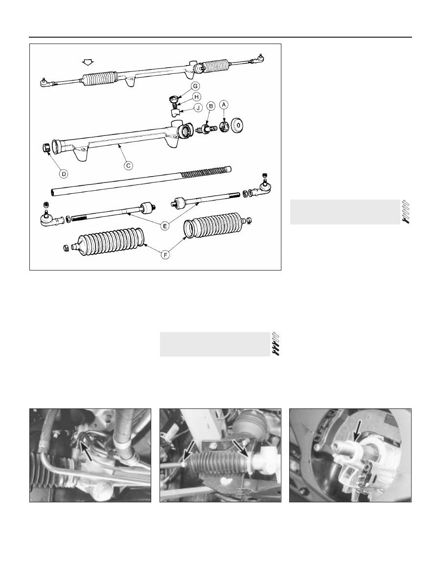
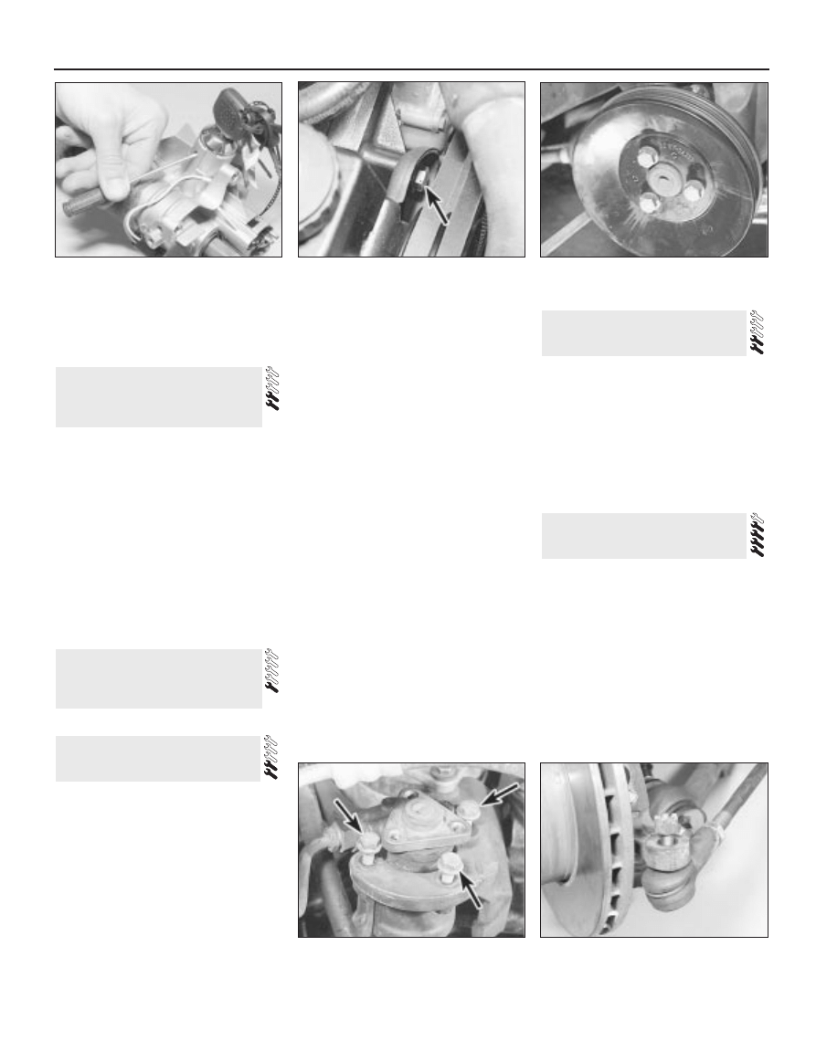
3 Remove the pinch-bolt and nut which
secure the intermediate shaft flexible coupling
to the pinion shaft (see illustration).
4 Slacken the track rod end locknuts by half a
turn each (see illustration).
5 Remove the split pin from the track rod
balljoint nuts. Unscrew the nuts, break the
balljoint tapers using a separator tool and
disengage the track rod ends from the
steering arms.
6 Remove the two bolts which secure the
steering gear to the crossmember. Lift out the
steering gear.
7 Mark the positions of the track rod ends on
the track rods, using paint or sticky tape, so
that they can be refitted in approximately the
same positions. Unscrew the track rod ends
and locknuts.
8 Commence refitting by screwing on the
locknuts and track rod ends, observing the
previously made position marks when
applicable.
9 Bring the rack to the straight-ahead
position. Do this by counting the number of
turns of the pinion needed to go from lock to
lock, then applying half that number of turns
from full lock on one side.
10 Offer the steering gear to the vehicle,
engaging the flexible coupling and loosely
fitting the securing bolts. Note that the master
spline on the pinion shaft mates with the
corresponding groove in the flexible coupling.
11 Tighten the two steering gear-to-
crossmember bolts to the specified Stage 1
torque. Slacken the bolts and retighten to the
Stage 2 torque. Finally tighten the bolts
through the angle specified for Stage 3.
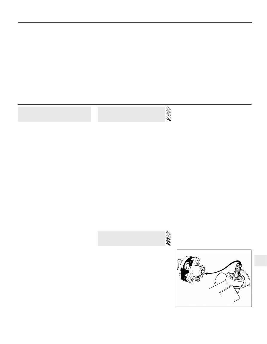
12 Make sure that the flexible coupling and
pinion shaft are properly engaged, then fit the
pinch-bolt and nut. Tighten the pinch-bolt to
the specified torque.
3 Steering gear - removal and
refitting
2 Power steering fluid - level
check and bleeding
1 General information
Steering and suspension 11•3
11
3.3 Master spline and groove on pinion
shaft and coupling
Torque wrench settings (continued)
Nm
lbf ft
Rear suspension
Driveshaft stub axle nut . . . . . . . . . . . . . . . . . . . . . . . . . . . . . . . . . . . . .
250 to 290
180 to 210
Final drive mounting to floor . . . . . . . . . . . . . . . . . . . . . . . . . . . . . . . . . .
20 to 25
15 to 18
Final drive mounting to rear cover . . . . . . . . . . . . . . . . . . . . . . . . . . . . .
40 to 50
30 to 37
Guide plate-to-floor bolts . . . . . . . . . . . . . . . . . . . . . . . . . . . . . . . . . . . .
41 to 51
30 to 38
Guide plate insulator bolt . . . . . . . . . . . . . . . . . . . . . . . . . . . . . . . . . . . .
69 to 88
51 to 65
Lower arm to crossmember . . . . . . . . . . . . . . . . . . . . . . . . . . . . . . . . . .
80 to 95
59 to 70
Brake anchor plate to lower arm . . . . . . . . . . . . . . . . . . . . . . . . . . . . . .
52 to 64
38 to 47
Anti-roll bar bracket bolts . . . . . . . . . . . . . . . . . . . . . . . . . . . . . . . . . . . .
20 to 25
15 to 18
Shock absorber mountings:
Top . . . . . . . . . . . . . . . . . . . . . . . . . . . . . . . . . . . . . . . . . . . . . . . . . . .
73 to 97
54 to 72
Bottom . . . . . . . . . . . . . . . . . . . . . . . . . . . . . . . . . . . . . . . . . . . . . . . .
68 to 92
50 to 68
Rear hub bolts . . . . . . . . . . . . . . . . . . . . . . . . . . . . . . . . . . . . . . . . . . . .
80 to 100
59 to 74
Wheels
Wheel nuts (steel or alloy wheels) . . . . . . . . . . . . . . . . . . . . . . . . . . . . . .
70 to 100
52 to 74
13 Refit the track rod ends to the steering
arms. Fit the balljoint nuts and tighten them to
the specified torque, then secure with new
split pins.
14 Nip up the track rod end locknuts, but do
not tighten them fully yet.
15 Refit the front wheels and wheel nuts.
Lower the vehicle and tighten the wheel nuts
to the specified torque.
16 Check the toe setting as described in
Section 19. When toe is correct, tighten the
track rod end locknuts fully.
Power-assisted steering
17 Proceed as described for manual steering
gear, but before removing the steering gear-
to-crossmember bolts, remove the clamp
plate bolt from the steering gear valve body
(see illustration).
18 Pull the fluid pipes out of the valve body.
Be prepared for fluid spillage. Plug or cap the
open pipes and orifices.
19 The steering gear may now be removed.
20 Refit in the reverse order to removal, using
new O-rings on the fluid pipes.
21 Bleed the steering gear hydraulic system
on completion.
1 Remove the track rod end on the side
concerned. Also remove the locknut.
2 Remove the bellows retaining clips and slide
the bellows off the track rod (see illustration).
3 On manual steering racks, apply a smear of
grease to the track rod
4 Fit the new bellows and secure with new
clips. Make sure that the ends of the bellows
are located in their grooves. Do not tighten the
outer clip yet - leave it slack until toe has been
checked after refitting.
5 Refit the track rod end locknut, followed by
the track rod end itself.
6 Repeat on the other side of the vehicle if
necessary.
Models before April 1992
1 Disconnect the battery negative lead.
2 Prise off the horn push pad from the centre
of the steering wheel.
3 Remove the three screws which secure the
horn switch plate. Withdraw the plate,
disconnect its wires and remove it.
4 Engage the steering lock, then undo and
remove the steering wheel nut. Unlock the
steering again.
5 Mark the relationship of the wheel to the
shaft, then pull the wheel off the shaft. Use a
puller if it cannot be removed by hand. Do not
use hammer blows, which may damage the
collapsible parts of the column and shaft.
6 Recover the spacer from below the steering
wheel (see illustration).
7 Refit by reversing the removal operations.
Tighten the steering wheel nut to the specified
torque.
Models from April 1992
8 The steering wheel can be removed and
refitted as described above whilst ignoring the
5 Steering wheel - removal and
refitting
4 Steering rack bellows - renewal
in vehicle
11•4 Steering and suspension
3.17 Clamp plate bolt (arrowed) is located
between two fluid pipes
4.2 Steering rack bellows retaining clips
(arrowed)
5.6 Spacer ring (arrowed) fits below
steering wheel
3.4 View of manual steering gear
A Pinion nut
B Pinion
C Rack housing
D Support bush
E Track rods
F Bellows
G Slipper plug
H Spring
J Slipper
reference to horn switch plate retaining
screws. Note that the wheel is retained by a
bolt, not a nut as on earlier models. To gain
access to the bolt, prise out the horn button
and disconnect the wiring connectors.
1 This operation is for correcting small errors
in steering wheel centralisation - up to 60°. For
larger errors, remove the steering wheel and
make a rough correction by repositioning the
wheel on refitting.
2 Drive the vehicle in a straight line on a level
surface. Note the angle by which the steering
wheel deviates from the desired straight-
ahead position.
3 Raise the front of the vehicle by driving it
onto ramps, or with a jack and axle stands
(see “Jacking”).
4 Slacken both track rod end locknuts. Also
slacken the steering rack bellows outer clips.
5 Make alignment marks between each track
rod end and its rod, so that the amount of
rotation applied can be accurately determined.
6 Turn both track rods in the same direction
to correct the steering wheel position. As a
rough guide, 19° of track rod rotation will
change the steering wheel position by 1°. To
correct error at the steering wheel, rotate both
track rods anti-clockwise (viewed from the
left-hand side of the vehicle), and the reverse
to correct as anti-clockwise errors. Both track
rods must be rotated by the same amount.
7 Tighten the bellows clips and the track rod
end locknuts when adjustment is correct.
Lower the vehicle.
1 Disconnect the battery negative lead.
2 Position the steering in the straight-ahead
position.
3 Remove the steering wheel. This is not
essential, but will improve access.
4 Working under the bonnet, disconnect the
intermediate shaft universal joint from the
steering column shaft.
5 Remove the steering column shrouds and
disconnect the switch multi-plugs. Do not
forget the ignition/starter switch.
6 Disconnect the bonnet release cable from the
operating lever on the underside of the column.
7 Prise out the driver’s side air vent. Remove
the under-dash insulation and trim panel on
the driver’s side, unclipping the bulb failure
module, where applicable.
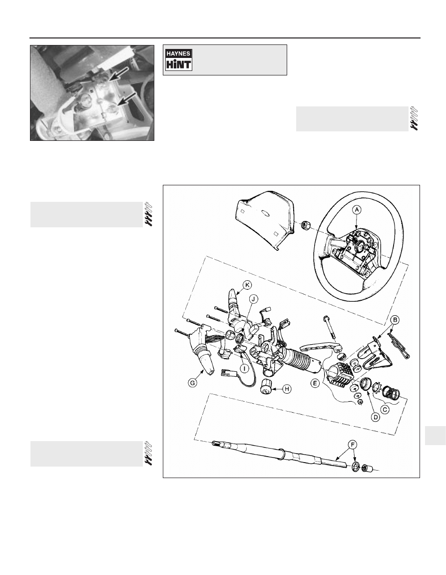
8 Remove the three nuts which secure the
column height adjuster to the mounting bracket
(see illustration). Remove the column assembly
by drawing it into the vehicle. Do not drop it or
otherwise mistreat it if it is to be re-used.
9 When refitting, have an assistant guide the
column shaft into the intermediate shaft
universal joint. Secure the column with the
three nuts inside the vehicle and adjust it to
the minimum length position, then tighten the
coupling pinch-bolt.
10 Complete refitting by reversing the
removal operations.
1 Remove the steering column (see
illustration).
2 Insert the key into the lock and turn it to
position 1. (If the lock has failed so that the key
will not enter, destructive methods will have to
be used.)
8 Steering column lock - removal
and refitting
7 Steering column - removal and
refitting
6 Steering wheel - centralising
Steering and suspension 11•5
11
7.8 Two of the three nuts (arrowed) which
secure the column height adjuster
8.1 View of steering wheel and column
A Steering wheel
B Mounting bracket and
spring
C Thrust washer and spring
D Lower bearing
E Height adjuster
F Column shaft and spire
washer
G Multi-function switch
H Ignition/steering lock
I Horn brush unit
J Upper bearing
K Multi-function switch
Make alignment marks
between the two shafts for
reference when reassembling.
3 Depress the locking button with a small
screwdriver. Draw the lock barrel out of its
housing using the key (see illustration).
4 Refit by reversing the removal operations.
1 The intermediate shaft and flexible coupling
are not available separately, and so must be
renewed as a unit.
2 Disconnect the battery negative lead.
3 Position the steering straight-ahead.
4 Remove the pinch-bolts which secure the
upper and lower ends of the intermediate
shaft. Free the universal joint from the column
shaft, then pull the flexible coupling off the
pinion shaft.
5 When refitting, engage the master spline on
the pinion shaft with the groove in the flexible
coupling.
6 Tighten the pinch-bolts to the specified
torque.
7 Reconnect the battery.
Refer to Chapter 1, Section 21.
All engines except DOHC
1 Disconnect the battery negative lead.
2 Wipe clean around the unions, then
disconnect the high pressure and return pipes
from the pump and the reservoir. Be prepared
for fluid spillage; take steps to keep fluid out of
the alternator.
3 Remove the pump drivebelt(s).
4 Remove the pump mounting, pivot and
adjustment bolts (as applicable) and lift the
pump from the engine (see illustration).
5 If a new pump is to be fitted, recover the
pulley and mounting plate from the old pump.
6 Refit by reversing the removal operations.
Adjust the drivebelt tension on completion and
bleed the steering hydraulic system.
DOHC engines
7 The pump is mounted on a bracket on the
front right-hand side of the cylinder block. To
improve access to the pump, firmly apply the
handbrake then jack up the front of the car
and support it securely on axle stands (see
“Jacking”).
8 Place a suitable container under the pump,
unscrew the fluid pipe unions, and drain the
fluid.
9 Remove the drivebelt with reference to
Chapter 1.
10 Prevent the pulley from rotating using a
strap wrench (which can be improvised using
an old drivebelt and a large socket and
wrench), and unscrew the three pulley
securing bolts (see illustration). Withdraw the
pulley.
11 Unscrew the three pump securing bolts
from the front of the pump bracket, and the
single bolt from the rear of the bracket, and
withdraw the pump (see illustration).
12 Refitting is a reversal of removal, bearing
in mind the following points:
a) Reconnect the fluid unions using new O-
rings.
b) On completion, top-up and bleed the
power steering fluid circuit.
1 Disconnect the battery negative lead.
2 Clean around the hose unions on the
steering gear. Remove the single securing
bolt, withdraw the hoses and catch the fluid
which will drain from the reservoir.
3 Clean around the hose unions on the pump.
Disconnect the unions and remove the hoses.
4 Refit in the reverse order to removal, using
new O-rings.
5 Top-up the steering fluid and bleed the
system.
1 Slacken the front wheel nuts, raise and
support the vehicle and remove the front
wheel on the side concerned.
2 Slacken the track rod end locknut by half a
turn.
3 Remove the split pin from the track rod end
balljoint nut. Unscrew the nut a few turns (see
illustration).
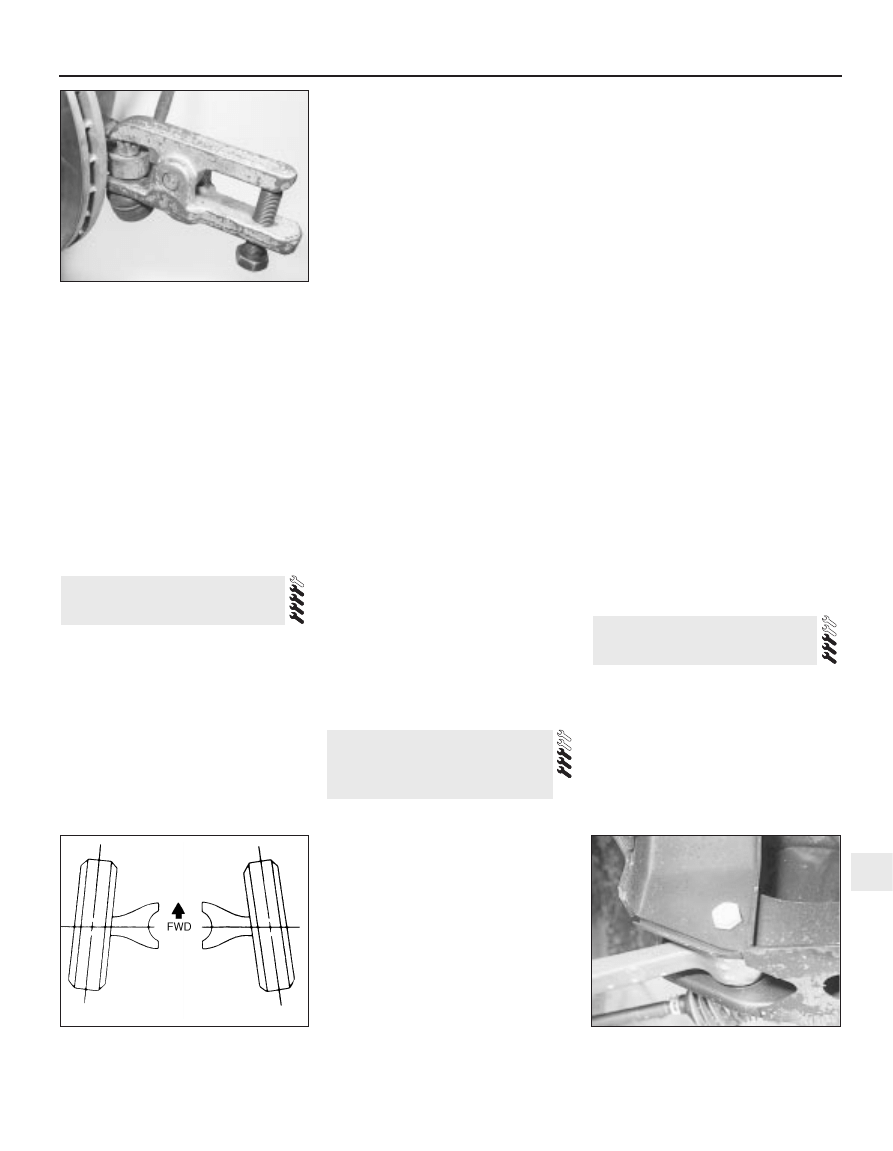
4 Break the balljoint taper with a proprietary
balljoint separator (see illustration). Remove
the separator and the nut and disengage the
track rod end from the steering arm.
5 Unscrew the track rod end from the track
rod, being careful not to disturb the locknut.
13 Track rod end - removal and
refitting
12 Power steering hoses -
removal and refitting
11 Power steering pump -
removal and refitting
10 Power steering pump
drivebelt - removal, refitting
and tensioning
9 Steering intermediate shaft
and flexible coupling - removal
and refitting
11•6 Steering and suspension
8.3 Depress the column lock locking button
11.11 . . . for access to the front pump
securing bolts (arrowed)
13.3 Track rod end balljoint nut unscrewed
11.4 Steering pump pivot bolt (arrowed) -
V6 model shown
11.10 Unbolt the power steering pump
pulley . . .
6 When refitting, screw the track rod end onto
the track rod as far as the locknut, then back it
off half a turn.
7 Insert the ball-pin into the steering arm.
Tighten the balljoint nut to the specified torque
and secure with a new split pin. Nip up the
track rod end locknut, but do not tighten it fully
yet.
8 Refit the roadwheel, lower the vehicle and
tighten the wheel nuts to the specified torque.
9 Check the toe setting as described in the
following Section. (This may not be strictly
necessary if the same track rod end has been
refitted, but is certainly advisable if any
components have been renewed.)
10 Tighten the track rod end locknut when
toe is correct.
1 Front wheel alignment is defined by camber,
castor, steering axis inclination and toe
setting. The first three factors are determined
in production; only toe can be adjusted in
service. Incorrect toe will cause rapid tyre
wear (see illustration).
2 Toe is defined as the amount by which the
distance between the front wheels, measured
at hub height, differs from the front edges to
the rear edges. If the distance between the
front edges is less than that at the rear, the
wheels are said to toe-in; the opposite case is
known as toe-out.
3 To measure toe, it will be necessary to
obtain or make a tracking gauge. These are
available in motor accessory shops, or one
can be made from a length of rigid pipe or bar
with some kind of threaded adjustment facility
at one end. Many tyre specialists will also
check toe free, or for a nominal sum.
4 Before measuring toe, check that all
steering and suspension components are
undamaged and that tyre pressures are
correct. The vehicle must be at approximately
kerb weight, with the spare wheel and jack in
their normal positions and any abnormal loads
removed.
5 Park the vehicle on level ground and bounce
it a few times to settle the suspension.
6 Use the tracking gauge to measure the
distance between the inside faces of the front
wheel rims, at hub height, at the rear of the
front wheels. Record this distance; call it
measurement A.
7 Push the vehicle forwards or backwards so
that the wheels rotate exactly 180°(half a turn).
Measure the distance between the front wheel
rims again, this time at the front of the wheels.
Record this distance; call it measurement B.
8 Subtract measurement B from
measurement A. If the answer is positive it is
the amount of toe-in; if negative it is the
amount of toe-out. Permissible values are
given in the Specifications.
9 If adjustment is necessary loosen the track
rod end locknuts and the outer bellows clips,
then rotate each track rod by equal amounts
until the setting is correct. Hold the track rod
ends in their horizontal position with a spanner
while making the adjustment.
10 Tighten the locknuts and outer bellows
clips.
11 Provided the track rods have been
adjusted by equal amounts the steering wheel
should be central when moving straight-
ahead. The amount of visible thread on each
track rod should also be equal.
1 Disconnect the battery negative lead.
2 Raise and securely support the front of the
vehicle.
3 Remove the suspension lower arm pivot
nuts and bolts (see illustration). Disengage
the arms from the crossmember.
4 Disconnect the steering column shaft from
the intermediate shaft universal joint.
5 Remove the two bolts which secure the
steering gear to the crossmember. Draw the
steering gear forwards so that it is clear of the
crossmember and support it by wiring it to the
frame rails.
6 It is now necessary to support the engine,
preferably from above, using a hoist or an
adjustable support bar resting on the wings or
suspension turrets. Alternatively a jack and
some wooden blocks may be used from
below, but this is bound to obstruct access to
some extent.
7 Remove the engine mounting lower
securing nuts. Raise the engine until the
mountings are just clear of the crossmember.
8 Release the brake pipe clips from the
crossmember and slide the brake pipes from
their slots. Be careful not to strain the pipes.
9 Support the crossmember and remove its
four securing bolts. Lower the crossmember
and remove it from the vehicle.
10 Commence refitting by offering the
crossmember to the frame rails. Insert the four
securing bolts and tighten them to the
specified torque.
11 Secure the brake pipes to the
crossmember.
12 Refit the steering gear to the
crossmember. Tighten its securing bolts to the
specified torque.
13 Insert the suspension arms into the
crossmember and secure them with the pivot
bolts and nuts. Do not tighten the nuts and
bolts yet, just nip them up.
14 Lower the engine onto the crossmember.
Make sure that the engine mountings locate
correctly into the holes in the crossmember.
Tighten the engine mounting nuts. The engine
support bar or hoist can now be removed.
15 Reconnect the steering column shaft to
the intermediate shaft. Tighten the pinch-bolt
to the specified torque.
16 Lower the vehicle onto its wheels, then
tighten the lower arm pivot bolts to the
specified torque.
17 Reconnect the battery.
1 Slacken the front wheel nuts. Raise and
support the front of the vehicle and remove
the front wheel.
2 Separate the track rod end from the steering
arm.
3 Unbolt the brake caliper, pull it off the disc
and tie it up out of the way. Do not allow it to
hang by its hose.
4 Remove the split pin from the suspension
lower arm balljoint nut. Slacken the nut a few
16 Front stub axle carrier -
removal and refitting
15 Front suspension
crossmember - removal and
refitting
14 Front wheel alignment -
checking and adjusting
Steering and suspension 11•7
11
13.4 Using a balljoint separator
14.1 Front wheel toe-in (greatly
exaggerated)
15.3 Front suspension lower arm pivot bolt
times, then use a proprietary balljoint
separator to break the taper (see illustration).
5 Use a stout piece of wood to lever the lower
arm downwards and free the balljoint from the
stub axle carrier.
6 Remove the ABS wheel sensor from its
hole.
7 Remove the spring clip from one of the
wheel studs and pull the brake disc off the
hub.
8 Remove the stub axle carrier pinch-bolt.
Spread the stub axle carrier by carefully
introducing a chisel or blunt instrument into its
slot. Draw the stub axle carrier off the
suspension strut and remove it.
9 Refit by reversing the removal operations,
noting the following points:
a) Tighten all fastenings to the specified
torque
b) Use new split pins, when applicable
c) Renew the wheel sensor O-ring if
necessary; clean the sensor and its bore,
and smear them with wheel bearing
grease
Models before August 1989
1 Remove the stub axle carrier as described
in the previous Section.
2 Screw the wheel nuts onto the studs to
protect the threads. Clamp the stub axle
carrier in a vice by means of the studs and
nuts; do not overtighten.
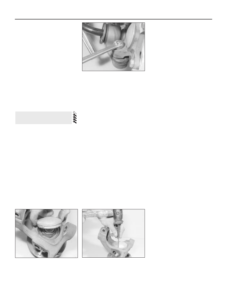
3 Remove the dust cap from the hub nut,
carefully levering it free (see illustration). A
new cap and a new hub nut will be required for
reassembly.
4 Undo the hub nut. This nut is very tight. The
right-hand hub nut has a left-hand thread,
therefore it is undone in a clockwise direction.
5 Remove the ABS rotor from below the hub
nut.
6 Lift the carrier off the stub axle, tapping it
with a mallet if necessary to free it. Remove
the bearing inner race from the carrier.
7 Prise the oil seal out of the carrier and
recover the bearing outer race.
8 Drive the bearing tracks out of the stub axle
carrier using a blunt drift and a hammer. Be
careful not to mark the bearing seats.
9 Clean all old grease and debris from the
stub axle carrier.
10 New bearing components are matched in
production and must only be fitted as a set.
Only the manufacturer’s approved
components should be used in order to obtain
the required long service life and freedom from
adjustment.
11 Drive the new bearing tracks into the
carrier, preferably using a suitable diameter
tube to seat them. Make sure the tracks are
fully seated.
12 Work some clean grease into the bearing
races. Use high melting-point lithium-based
grease (to Ford spec. SAMIC-9111A or
equivalent). Make sure all the spaces between
the rollers are filled; do not pack grease into
the space between the inner and outer
bearings however.
13 Fit the bearing outer race. Grease the lips
of a new oil seal and fit it to the stub axle
carrier, lips facing inwards. Seat the seal with
a pipe or large socket and a mallet.
14 Offer the carrier to the stub axle, tapping it
home if necessary. Fit the bearing inner race
over the stub axle.
15 Refit the ABS rotor, dished face
uppermost.
16 Fit a new hub nut (left-hand thread on the
right-hand hub) and tighten it to the specified
torque.
17 Fit a new dust cap and seat it by tapping
round the rim (see illustration).
18 Refit the stub axle carrier.
Models from August 1989
19 Modified front wheel bearing assemblies
were fitted to all models after 1989. The
modified bearings are of similar design, but
are interference fit type bearings. This was to
reduce the amount of endfloat present at the
wheel hub and to improve bearing preload
tolerances. This was achieved by increasing
the diameter of the stub axle, thus causing the
axle to be an interference fit in the bearing.
Note that the modified bearings can be fitted
to earlier models which were originally
equipped with non-interference fit front wheel
bearings. Note: Due to the design of the
interference fit bearings, a suitable heavy duty
bearing puller and a hydraulic press and
several suitable mandrels will be required to
remove the original bearing and install the new
one.
20 Interference fit front wheel bearings can be
removed and refitted as described above,
noting the following points.
a) It will be necessary to press or draw the
stub axle out of the carrier using a
hydraulic press or a suitable bearing
puller.
b) Draw the outer bearing off the stub axle
using a suitable bearing puller.
c) Press new bearing tracks into the hub
carrier using a suitable tubular spacer
which bears only on the tracks outer edge.
d) Pack the new outer bearing with Ford
grease (SAM-1C9111-A) and press the
bearing into the carrier.
e) Press a new seal into position in the
carrier and pack all cavities with the
specified grease.
f) Position the hub carrier over the stub axle
and press the carrier onto the axle using a
suitable tubular spacer which bears only
on the bearing track outer edge.
g) Pack the new inner bearing with the
specified grease then press the bearing
onto the stub axle, using a suitable tubular
spacer, whilst rotating the hub carrier to
ensure that the bearing is correctly seated.
h) Whilst tightening the hub nut to the
specified torque, rotate the hub carrier to
ensure that the bearing preload is correct
and bearings are correctly seated. Once
the nut is tightened to the specified
torque, rotate the hub carrier 20 times to
settle the bearings in position then
recheck that the hub nut is tightened to
the specified torque. Pack the inner
bearing with the specified grease and fit a
new dust cap.
17 Front wheel bearings -
renewal
11•8 Steering and suspension
16.4 Slackening the front suspension lower
arm balljoint nut
17.17 Seating the new dust cap
17.3 Removing the dust cap from the stub
axle carrier to expose the hub nut
1 Raise the vehicle on ramps or on a hoist, so
that the weight is still on the wheels.
2 Remove the lower arm pivot nut and bolt
(see illustration).
3 Remove the anti-roll bar end nut, dished
washer and plastic cover. Note which way
round these components are fitted.
4 Now raise and support the vehicle so that
the front wheels are off the ground.
5 Remove the split pin from the lower arm
balljoint nut. Back off the nut a few turns,
break the taper with a balljoint separator, then
remove the nut and free the balljoint from the
stub axle carrier.
6 Pull the lower arm off the anti-roll bar and
remove it.
7 If the balljoint is defective, the whole arm
must be renewed. The dust boot can be
renewed separately if required.
8 The anti-roll bar bushes (compliance
bushes) can be removed by cutting off their
flanges with a chisel, then pressing or tapping
out the remains. Fit new bushes by tapping
them home with a tube or socket.
9 The pivot bush can be pressed out using a
bench vice and a couple of large sockets or
suitable pieces of tube. The new pivot bush
should be lubricated with soap or glycerine
(not oil or grease) before being fitted in a
similar fashion. Do not keep the new bush
compressed in the tube for longer than
necessary, in case it becomes permanently
distorted.
10 Commence refitting by offering the arm to
the anti-roll bar. Make sure that the shallow
dished washer and the plastic cover are fitted
on the inboard side of the bar (furthest from
the nut).
11 Refit the balljoint to the stub axle carrier.
Tighten the castellated nut to the specified
torque and secure it with a new split pin.
12 Fit the pivot end of the arm into the
crossmember and secure it with the pivot nut
and bolt. Jacking the vehicle up or down to
vary the loading on the wheels may help to get
the holes lined up. Do not tighten the pivot nut
and bolt yet.
13 Lower the vehicle back onto its wheels.
14 Fit the deep dished washer and the plastic
cover over the end of the anti-roll bar. Fit the
nut and tighten it to the specified torque.
15 Tighten the lower arm pivot nut and bolt to
the specified torque.
1 Raise the vehicle on ramps or a hoist, so
that the weight is still on the wheels.
2 Unbolt the two anti-roll bar clamps (see
illustration).
3 Now raise and support the vehicle with the
wheels free.
4 Remove the two nuts which hold the ends
of the anti-roll bar to the lower arms. Recover
the plastic covers and deep dished washers.
5 Remove one lower arm pivot nut and bolt.
Prise the lower arm out of the crossmember
and work the anti-roll bar free from it.
6 Pull the anti-roll bar out of the other lower
arm and remove it. Recover the other
compliance bush covers and washers.
7 Refit by reversing the removal operations,
but do not finally tighten any fastenings until
the weight of the vehicle is back on the
wheels. Tighten in the following order:
a) Anti-roll bar clamps
b) Anti-roll bar-to lower arm nuts
c) Lower arm pivot nut and bolt
8 Make sure that the anti-roll bar clamp
bushes are not twisted on completion.
Compliance bushes
1 These are described in Section 18. It is not
strictly necessary to remove the lower arms to
renew these bushes, though obviously access
is not good with the arms installed.
Clamp bushes
2 Although it is possible to remove and refit
the clamp bushes without removing the anti-
roll bar, since the bushes are split, this is not
recommended by the makers.
3 Remove the anti-roll bar as described in the
previous Section.
4 Slide the clamp bushes off the anti-roll bar,
if necessary prising them open a little first.
5 Lubricate the new bushes with glycerine or
soap and slide them into position with the split
facing forwards.
6 Refit the anti-roll bar.
1 Slacken the front wheel nuts, raise and
support the vehicle and remove the front
wheel.
2 Disconnect the battery negative lead.
3 Unbolt the brake caliper and suspend it
nearby so that the flexible hose is not strained.
4 Remove the ABS sensor from the stub axle
carrier.
5 Separate the track rod end and suspension
lower arm balljoints from the stub axle carrier.
6 Unclip the ABS/brake pad wear wiring from
the strut.
7 Remove the dust cover from the top of the
strut.
8 Have an assistant support the strut.
Remove the three nuts which secure the strut
to the turret (see illustration). Do not undo
the centre nut.
9 Lower the strut out of the turret and remove
it.
10 Refit by reversing the removal operations.
Do not fully tighten the strut-to-turret nuts until
the weight of the vehicle is back on its wheels.
21 Front suspension strut -
removal and refitting
20 Front anti-roll bar bushes -
renewal
19 Front anti-roll bar - removal
and refitting
18 Front suspension lower arm -
removal, overhaul and refitting
Steering and suspension 11•9
11
19.2 A front anti-roll bar clamp
21.8 Two of the three nuts (arrowed)
securing the suspension strut to the turret
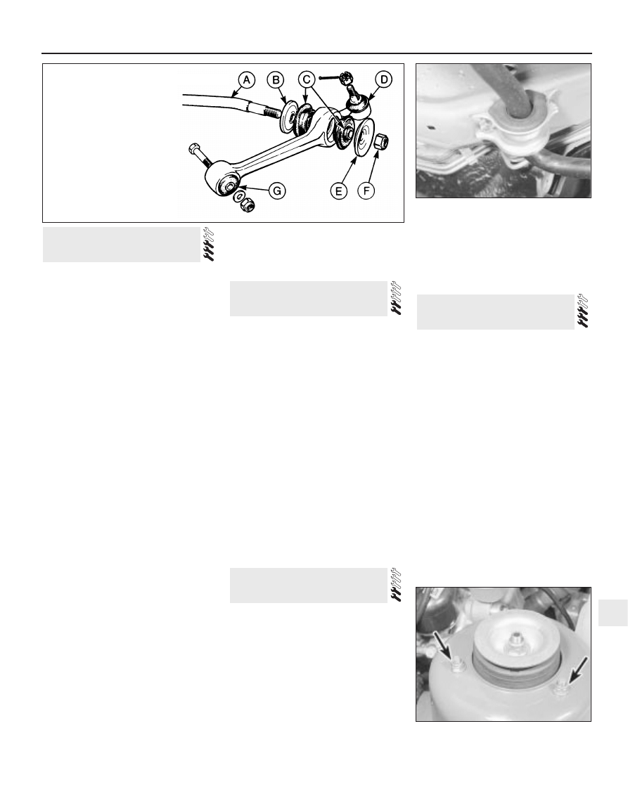
18.2 Front suspension lower arm components
A Anti-roll bar
B Rear dished washer and cover
C Bushes
D Balljoint
E Front dished washer and cover
F Locknut
G Pivot bush
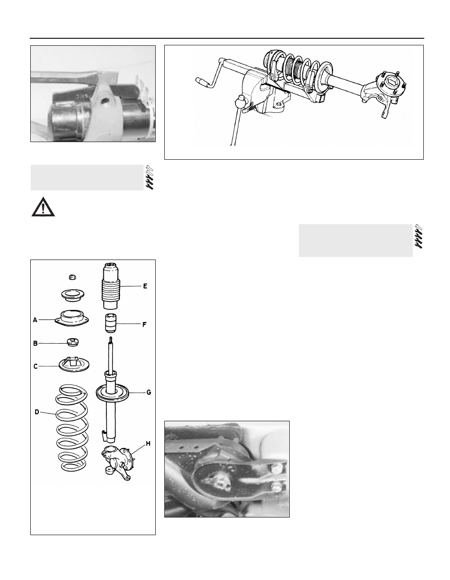
1 With the strut removed, clamp it in a vice
with protected jaws.
2 Remove the stub axle carrier pinch-bolts.
Spread the carrier by carefully introducing a
chisel or blunt screwdriver into the crack, then
slide it off the strut (see illustration).
3 Fit spring compressors to the strut.
Compress the spring until it is no longer
tensioning the strut. Make sure that the
compressors are secure (see illustration).
4 Hold the piston rod with a hexagon key and
remove the piston rod nut. Also remove the
dished retainer.
5 Remove the top mount, the bearing and the
spring upper seat (see illustration).
6 Carefully lift off the compressed spring.
Place it where it will not be knocked or jarred.
7 Remove the shock absorber gaiter and
bump stop.
8 Examine all components for wear and
damage and renew as necessary. The shock
absorber must be renewed if it is leaking, or if
it shows uneven resistance when “worked”
with its lower end clamped in a vice. In theory
springs and shock absorbers should be
renewed in pairs in order to maintain balanced
handling characteristics.
9 Commence reassembly by sliding the bump
stop onto the shock absorber piston rod. Refit
the gaiter.
10 Make sure that the spring seats are clean,
then fit the compressed spring to the lower
seat.
11 Refit the spring upper seat, the bearing
(small hole upwards) and the top mount.
12 Refit the dished retainer and the piston rod
nut. Hold the piston rod and tighten the nut.
13 Carefully release the spring compressors.
Make sure that the ends of the spring are
correctly located in the spring seats.
14 Spread the stub axle carrier again. Slide it
onto the strut, remove the spreader and refit
the pinch-bolt. Tighten the pinch-bolt to the
specified torque.
15 Refit the strut to the vehicle.
Models before 1987
1 Raise the rear of the vehicle and support it
securely under the frame rails.
2 Remove the exhaust system.
3 Remove the propeller shaft.
4 Release the handbrake cable from the
equaliser yoke by removing the circlip from the
handbrake lever pin. Release the cable from
its floor brackets.
5 Disconnect the brake flexible hoses from
the rear brake pipes.
6 Disconnect the ABS and brake pad wear
sensor wires (as applicable). Free the wires
from the suspension lower arms.
7 Unbolt the two anti-roll bar brackets from
the floors.
8 Disconnect the ride height control sensor
and the shock absorber air lines, when so
equipped.
9 Lower the vehicle onto its wheels in order to
load the rear springs a little. Place a jack under
the final drive unit and support it.
10 Unbolt and remove the two guide plates
(see illustrations). The centre bolt on each
plate is retained by a lockwasher which must
be released first.
11 Unbolt the final drive unit rear mounting
from the floor.
12 Remove the luggage area side trim, then
remove the rear shock absorber upper
mounting bolts.
13 Raise and support the rear of the vehicle
again. Withdraw the rear suspension and final
drive assembly.
14 Refit by reversing the removal operations.
Tighten all fastenings to the specified torque,
when known. When applicable use new O-
rings on the ride height control line unions.
23 Rear suspension and final
drive assembly - removal and
refitting
22 Front suspension strut -
dismantling and reassembly
11•10 Steering and suspension
22.2 Spreading the stub axle carrier clamp
22.3 Spring compressors fitted to a front suspension strut
22.5 Front suspension strut components
A Top mount
B Bearing
C Spring upper seat
D Spring
E Gaiter
F Bump stop
G Shock absorber
and spring lower
seat
H Stub axle
Warning: Spring compressors of
adequate rating must be used for
this job. The use of makeshift or
inadequate equipment may result
in damage and personal injury.
23.10a One of the rear suspension guide
plates
15 Bleed the brake hydraulic system and
adjust the handbrake on completion.
Models from 1987
16 From 1987, the tab washer which secures
the guide plate centre bolt on each side has
been deleted. A self-locking bolt and plain
washer are used instead.
17 The new bolt and washer should be fitted
to earlier models if the old bolt has been
removed for any reason. The tab washer
should be discarded.
18 The tightening torque for the new bolt
remains the same as that given for the original.
1 Remove the wheel trim. Apply the
handbrake and chock the front wheels.
2 Slacken the driveshaft stub axle. This nut is
very tight. The left-hand nut has a left-hand
thread, therefore it is undone clockwise.
3 Remove the brake disc.
4 Remove the driveshaft stub axle.
5 Remove the four bolts which secure the
hub. Pull the hub off the driveshaft stub,
leaving the disc splash shield loose.
6 Refit by reversing the removal operations.
Carry out the final tightening of the driveshaft
stub nut with the wheels on the ground.
1 Remove the rear hub as described in the
previous Section (see illustration).
2 Prise out both oil seals from the hub.
Recover the bearing races.
3 Drive the bearing tracks out of the hub with
a hammer and a blunt drift.
4 Clean grease and debris from the hub and
clean up any burrs or nicks.
5 Fit the new bearing tracks, pressing them in
squarely with the help of a piece of pipe or
tube.
6 Thoroughly grease the bearing races and
pack the lips of the oil seals with grease.
7 Fit the races and the oil seals, lips inwards.
Seat the oil seals with a mallet and the pipe or
tube.
8 Refit the rear hub.
1 This procedure is only specified by the
manufacturers as applying to the rear wheels,
but there is no reason to believe that it will not
work on the front.
2 Remove the rear wheel, brake caliper and
brake disc.
3 Drive the wheel stud out of the hub flange.
4 Insert the new stud from the inboard side of
the flange. Engage the splines by hand
pressure, then draw the stud into place with a
wheel nut and progressively thicker spacers
(see illustration).
5 Refit the brake disc, caliper and wheel.
1 Raise and support the rear of the vehicle.
2 Unbolt the driveshaft outboard flange from
the stub. It is secured by six Torx screws.
3 Disconnect the anti-roll bar from the link rod
by prising it free. On models with ride height
control, also disconnect the height sensor
from the anti-roll bar link rod.
4 Free the brake pipe and flexible hose from
the brackets next to the spring. If it is the left-
hand spring which is being removed, also
unbolt the brake pipe T-piece from the floor.
5 Raise a jack under the rear suspension
lower arm to load the spring.
6 Unbolt the shock absorber from the lower
arm.
27 Rear spring - removal and
refitting
26 Wheel stud - renewal
25 Rear wheel bearings -
renewal
24 Rear hub - removal and
refitting
Steering and suspension 11•11
11
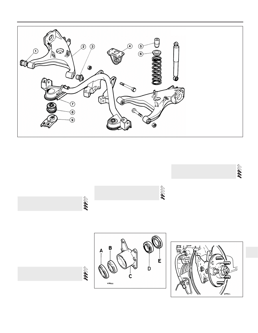
25.1 Rear hub components
A Outer oil seal
B Outer bearing
C Hub
D Inner bearing
E Inner oil seal
26.4 Fitting a new wheel stud using a nut
and spacer
23.10b Rear suspension components
1 Lower arm outer bush
2 Lower arm
3 Lower arm inner bush
4 Final drive rear mounting
5 Buffer
6 Spring seat
7 Crossmember
8 Insulator
9 Guide plate
7 Unbolt the guide plate from the body on the
side concerned.
8 Carefully lower the jack until the spring is no
longer under tension. Remove the spring and
the rubber buffer.
9 Refit by reversing the removal operations,
tightening all fastenings to the specified torque
when known.
Note: Ford tool No 15-014, or locally made
equivalent, will be required for this job.
1 Raise and support the rear of the vehicle.
2 Flatten the lockwasher which secures the
guide plate centre bolt. Remove the centre
bolt and the two bolts which hold the guide
plate to the floor; remove the guide plate.
3 Wedge a piece of wood between the
crossmember and the floor.
4 Draw the insulator out with the special tool
(see illustration).
5 Smear the new insulator with glycerine or
liquid soap, then press it in as follows.
6 Use the special tool spindle or other long
M12 bolt. Screw a nut up to the bolt head,
then fit a plain washer and the insulator onto
the bolt. Pass the bolt through the hole in the
crossmember and screw it into the floor, then
press the insulator home by winding the nut
and washer up the bolt.
7 Remove the installation tool and the wood.
8 Refit the guide plate, tightening the bolts to
the specified torque. Secure the centre bolt
with the lockwasher.
9 Lower the vehicle.
1 Remove the rear hub.
2 Disconnect both rear brake flexible hoses
from the brake pipes. Free the brake pipes
from the brackets on the lower arms.
3 Unclip the handbrake cable from the lower
arm.
4 Remove the rear spring.
5 Remove the lower arm-to-crossmember
bolts. Withdraw the lower arm.
6 Renew the rubber bushes if wished, using
lengths of tube or sockets and a vice, or large
nuts and bolts. Lubricate the new bushes with
glycerine or liquid soap.
7 Refit by reversing the removal operations,
tightening the lower arm-to-crossmember
bolts with the weight of the vehicle back on its
wheels. Bleed the brake hydraulic system on
completion.
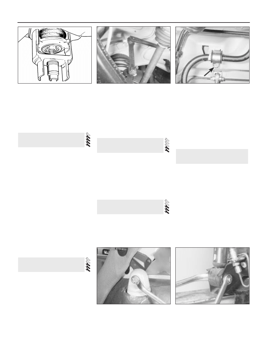
1 Raise and support the rear of the vehicle.
2 Separate the anti-roll bar from the link rods
on each side by prising them free (see
illustration).
3 Unbolt the two anti-roll bar brackets.
Remove the bar, brackets and bushes (see
illustration).
4 Refit by reversing the removal operations.
Tighten the bracket bolts to the specified
torque.
1 Working inside the vehicle, remove the
luggage area side trim to gain access to the
shock absorber top mounting.
2 Raise and support the rear of the vehicle.
Raise a jack under the rear suspension lower
arm to take the load off the shock absorber.
3 On models with ride height control,
disconnect the air line from the shock
absorber.
4 Unbolt the shock absorber top mounting
(see illustration).
5 Unbolt the shock absorber lower mounting
(see illustration). Pull the shock absorber out
of the lower mounting bracket and remove it.
6 Refit by reversing the removal operations.
Tighten the shock absorber mountings to the
specified torque. On models with ride height
control, use new O-rings on the air line union.
The ride height control system is an optional
extra, designed to keep the rear suspension
height constant regardless of vehicle load.
This is obviously useful if heavy loads are often
carried, or if the vehicle is used for towing.
The main components of the system are a
height sensor, a compressor and two special
rear shock absorbers. The compressor
supplies air to the shock absorbers, so
“pumping up” the rear suspension, when so
commanded by the height sensor. Other
components include the connecting pipes,
electrical wiring and a compressor relay. The
relay is mounted behind the glovebox.
Variations in vehicle height are not
recognised by the system for approximately
20 seconds, in order to prevent responses to
temporary changes such as those induced by
32 Ride height control system -
general information
31 Rear shock absorber -
removal and refitting
30 Rear anti-roll bar - removal
and refitting
29 Rear suspension lower arm -
removal and refitting
28 Rear crossmember insulator
- removal and refitting
11•12 Steering and suspension
28.4 Drawing out an insulator with the
special tool
31.4 Undoing a rear shock absorber top
mounting
31.5 Undoing a rear shock absorber lower
mounting
30.2 Rear anti-roll bar link rod
30.3 A rear anti-roll bar bracket - bolt
arrowed
cornering or braking. Control circuitry also
prevents the compressor being energised for
more than five minutes continuously, as could
otherwise happen if the system sprang a leak.
No repairs to individual components are
possible. Apparent control faults should be
referred to a Ford dealer before embarking on
an expensive programme of testing by
substitution. Always use new O-rings on the
pipe unions once they have been disturbed.
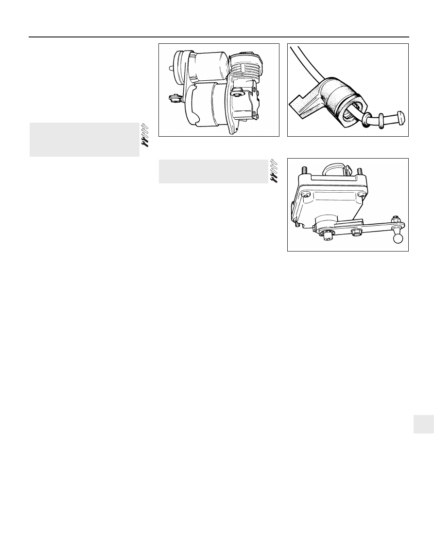
1 Disconnect the battery negative lead.
2 Raise and support the front of the vehicle.
3 Remove the compressor cover (front left-hand
side of engine) which is secured by four screws.
4 Disconnect the air pipe and the power
supply leads from the compressor (see
illustration).
5 Remove the three bolts which secure the
compressor to the bracket. Withdraw the
compressor, at the same time disconnecting
the suction line and the control multi-plug.
6 Refit by reversing the removal operations;
use new O-rings on the air pipe union (see
illustration).
1 Disconnect the battery negative lead.
2 Raise and support the rear of the vehicle to
gain access to the sensor, located to the right
of the rear crossmember (see illustration).
3 Unclip the linkage balljoint from the sensor.
4 Disconnect the sensor multi-plug.
5 Unbolt the sensor from the floor and remove
it.
6 Do not attempt to adjust the sensor by
altering the position of the control arm.
7 Refit by reversing the removal operations.
34 Ride height control sensor -
removal and refitting
33 Ride height control
compressor - removal and
refitting
Steering and suspension 11•13
11
33.4 Ride height control compressor
33.6 Detail of ride height control pipe union
34.2 Ride height control height sensor

11•14
Notes
Wyszukiwarka
Podobne podstrony:
Jaguar XJ8 XJR Steering Suspension
11 Front Wheel Suspension Steering
11 Front Wheel Suspension Steering
07 E65 Suspension & Steering
ARTICLE SUSPENSION STRUT FRONT REPLACE INSTALL
M32d Rear Suspension
17 steering system
50 Steering Column
50 Steering Column
26 Front Suspension
ARTICLE SUSPENSION STRUT FRONT DISASSEMBLE REASSEMBLE
Scorpions
Scorpion
C 06 0 SteeringGearFailure
61 STEERING COLUMN SWITCHES
C102968 0 SERVICE LOCAL STEERING
suspenser, Studia (Geologia,GZMIW UAM), II rok, Hydrogeologia, Egzamin, zagadnienia
POWER STEERING
więcej podobnych podstron