
Initial Print Date: 05/06
Table of Contents
Subject
Page
Fundamentals of Coding & Programming . . . . . . . . . . . . . . . . . . . . . . .4
What is the Purpose of Coding and Programming? . . . . . . . . . . . . . . . . .6
Where is Data Stored in a Control Module? . . . . . . . . . . . . . . . . . . . . . . . .8
(Electrically Programmable Read Only Memory) . . . . . . . . . . . . . . . . .8
(Electrically Erasable Programmable Read Only Memory) . . . . . . . . .9
What is needed to Code and Program? . . . . . . . . . . . . . . . . . . . . . . . . . . .9
Complete Software Update Programming Procedures . . . . . . . . . . . . .10
Five Pillars for Programming a Vehicle . . . . . . . . . . . . . . . . . . . . . . . . .10
Vehicle Coding Information . . . . . . . . . . . . . . . . . . . . . . . . . . . . . . . . . . .11
ZCS Stored Location in Vehicle . . . . . . . . . . . . . . . . . . . . . . . . . . . . . . .14
Accessing ZCS Information Label . . . . . . . . . . . . . . . . . . . . . . . . . . . .15
Control Modules Flash (EEPROM) Programming . . . . . . . . . . . . . . .19
Determination Process for DME EEPROM . . . . . . . . . . . . . . . . . . . . . . .19
Coding & Programming . . . . . . . . . . . . . . . . . . . . . . . . . . . . . . . . . . . . . . .20
Coding & Programming
Revision Date: 05/10

Subject
Page
BLANK
PAGE

3
Coding & Programming
Coding & Programming
Model: All
Production: All
After completion of this module you will be able to:
• Distinguish between Coding & Programming
• Understand the importance of Coding & Programming
• Understand where data is stored in a Control Module
• Know the 5 (+1) reasons for programming a vehicle
4
Coding & Programming
What is Coding?
It is a process utilized by BMW, which groups system specific operating requirements
(Data) together and then assigns a label/code to each of these groups of data. The
various groups of data are all pre-loaded into system specific “codable” control modules,
along with a basic set of operating instructions (Program).
Types of operating requirements:
• Nominal values of device input signals (0.25V to 2.5V, 5W - 25W, ...)
• Type of device input signal (PWM, square wave, analog ...)
• Operational parameters (device activation/deactivation time, ...)
• Market specific operations (O2 Sensors, Fuel Type, Emission Control, ...)
• Country Specific Regulations (U.S., Canada, Japan, UK, ECE, ...)
• Powertrain Configurations (Manual, Auto, Diesel, ...)
The procedure of assigning one specifically labeled group of data to the operating
program of a specific control module/component is referred to as “coding”.
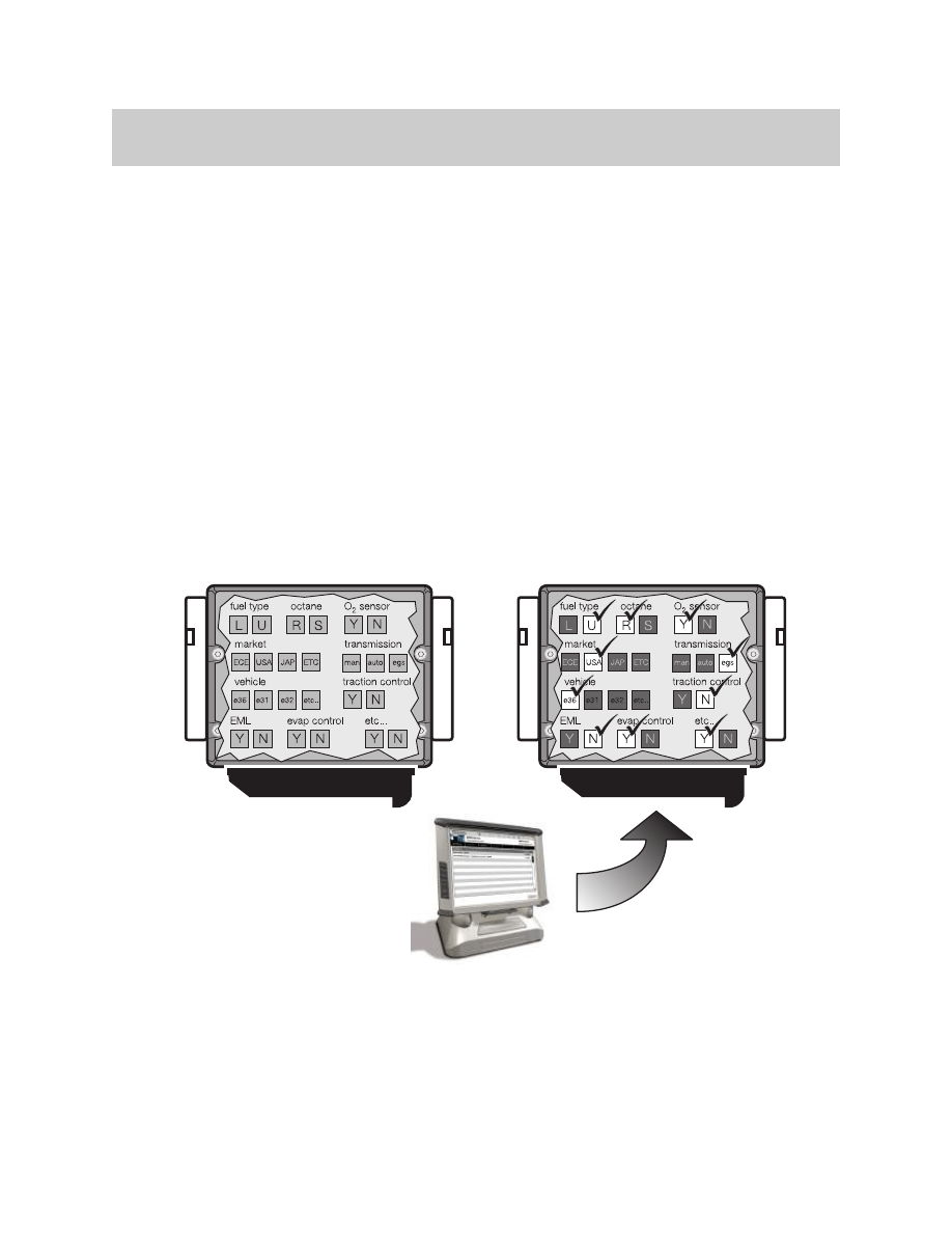
A “codable” control module has a basic operating program already installed along with
several specific variations of operating data. The coding process allows a specific set of
operating data to be assigned to the basic operating program of that module/component,
with respect to its specific application.
BEFORE CODING
AFTER CODING
Coding allows a specific
set of data already present
in the module to be selected.
BMW Diagnosis and information system
Hassermen
Bsaljeoi
Gllufpjenr
Rusdljfoiv
TIS
Nerucvleu
Frluelkdmvdk
Wsdkurovcn
kjdfkjorir
Hassermen
Fundamentals of Coding & Programming
Coding can be performed for some systems/components:
• Selecting customer specific system operational settings from a list of available
features (VKM).
• Automatically by selecting a specific coding process available via ISTA/P.
• By using a coded ground wire to a module.
• Determined at the factory.
Note: Codable control modules/components are system specific,
which means that not all control modules are codable.
What is Programming?
It is a process utilized by BMW to load application/system specific operating instructions
(Program) into a module/component which already has the systems operating require-
ments (Data) installed, plus it can be used as a means of updating data and operating
instructions previously installed in a control module.
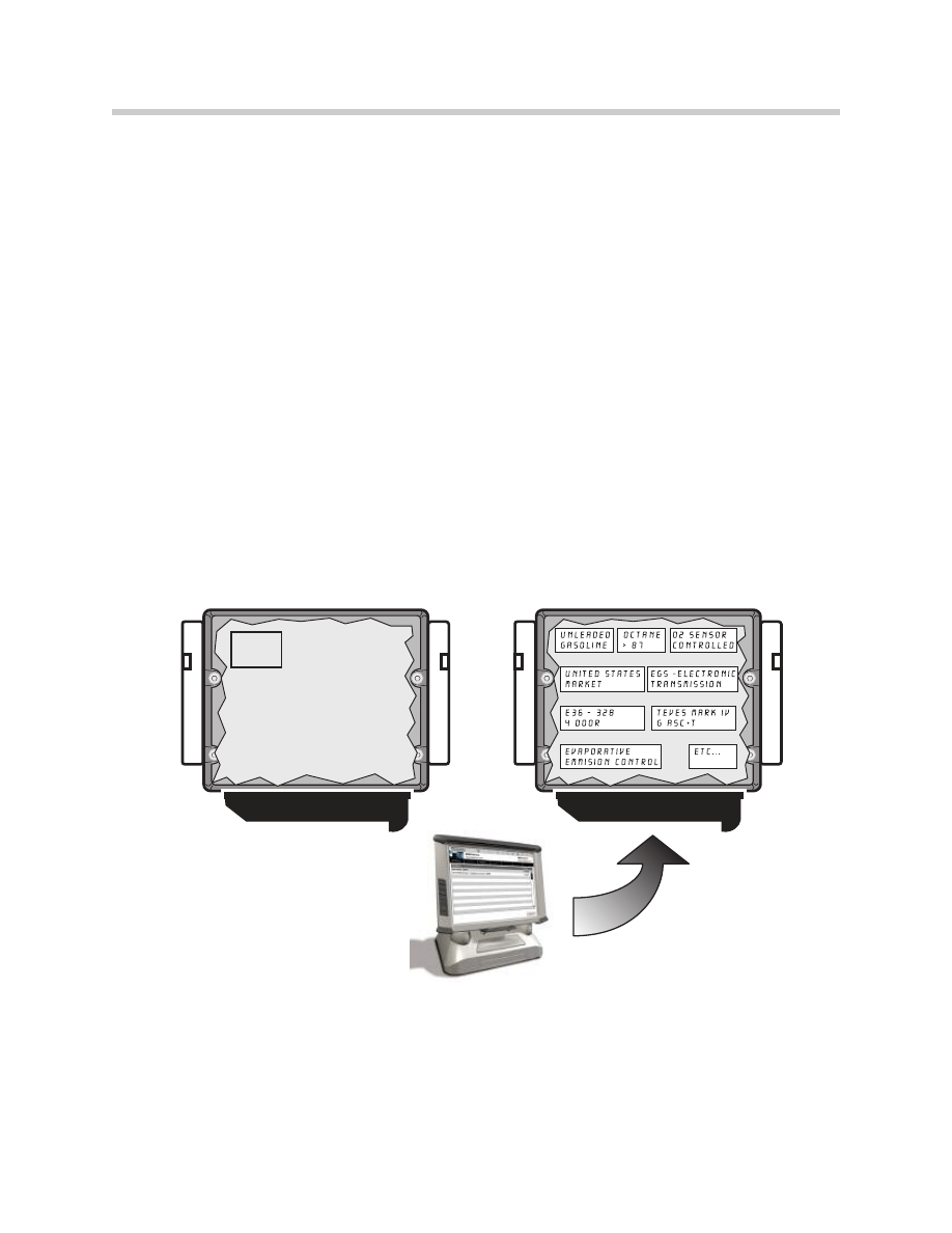
Basic programmable control modules have a pre-defined set of operating data already
installed which allows the module to be fairly generic until a specific operational program
is installed.
Programming of system control modules is performed using ISTA/P.
5
Coding & Programming
BEFORE PROGRAMMING
AFTER PROGRAMMING
Programming loads control
functions instructions into
a specific control module.
No specific operational
program installed.
BASIC
DATA
BMW Diagnosis and information system
Hassermen
Bsaljeoi
Gllufpjenr
Rusdljfoiv
TIS
Nerucvleu
Frluelkdmvdk
Wsdkurovcn
kjdfkjorir
Hassermen

Note: Programmable control modules are system specific and not all control
modules are programmable using workshop equipment like ISTA/P.
The ability to program a module is limited to the number of times it
has already been programmed and the hardware version of the control
module itself.
What is the Purpose of Coding and Programming?
As a global manufacturer, BMW must design a large variety of control modules to meet
numerous vehicle requirements pertaining to issues such as:
• Country Specific Regulations (U.S., Canada, Japan, UK, ECE, ...)
• Vehicle Equipment Level (Phone, Navigation, HiFi, IHKA, IHKR, ...)
• Vehicle Powertrain Configurations (Manual, Auto, ...)
• System Specific Operating Requirements (Nominal values, type of input signal, ...)
By using Coding and/or Programming, the large variety of control modules needed can be
reduced to a smaller number of model specific hardware variations.
Codable control modules contain:
• A common operating program
• A large number/variety of specific operating data groups
In order to use this type of control module it must first be CODED to ensure that the
operating data specific to that vehicle/model application is used by the operating program
of the control module.
Programmable control modules contain:
• The required/specific operational data
• No operating program
In order to use this type of control module it must first be PROGRAMMED to ensure that
the operating program specific to the vehicle/model application is used.
Prior to the availability of Coding and Programming in the workshop this task could only
be performed at the factory.
Initially the factory installed Control Module(s) with a common operating program or data
into vehicles and as theses vehicles reached various points in the assembly process the
control modules were updated with the required operating data or program specific to
the application for that particular vehicle. Since replacement parts always need to be
available, parts inventory needed to contain all variations of preprogrammed control
modules installed in all varieties of vehicles that were manufactured. This was not a
big problem in the early years, when the variety/quantity of models was smaller.
6
Coding & Programming
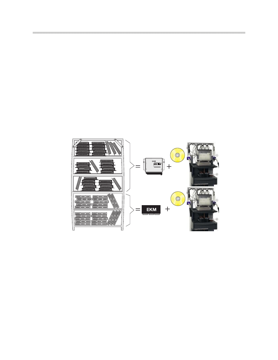
As the number of control modules and the complexity of the various systems installed
into vehicles increased, the number of modules that needed to be stored in parts invento-
ry began to increase as well. Eventually this led to the stocking of hundreds of different
control modules that were either pre-programmed or pre-coded for a specific application
and model, but only differed slightly in the way they were coded or programmed.
Pre-programmed and pre-coded control modules always needed to be available in the
event a control module failed once the vehicle left the factory floor, since this was the only
place programming & coding procedures could be performed. In order for repairs to be
made quickly, dealers were required to maintain a stock of several varieties of control
modules, since technicians could only remove the failed module and installed a new pre-
programmed or pre-coded module into the vehicle.
As a result of having to maintain a very large inventory of pre-programmed and pre-coded
control modules in parts inventory, it was decided to make coding and eventually pro-
gramming available in BMW workshops.
The following advantages have occurred since programming and coding can be per-
formed in the workshop:
• Fewer control module hardware versions are needed (only need basic
control modules)
• Lower parts and inventory costs
• Able to update software in a control module without having to replace
the module (Re-Code/ Re-Program to address service Measures)
• Ability to add special equipment features to existing control modules
(DWA, Day Time Running Lights, ...)
• Customization of vehicle operation (Conversions, VKM, A/C, ...)
7
Coding & Programming
DME
The means by which coding or programming information is provided to a control module
varies and is determined by the vehicle, model year and type of module(s) installed.
BMW currently uses the following methods to perform Coding or Programming:
• Coding Plug
• DME variant Coding
• Coding Code
• Central Coding Key (ZCS) or Vehicle Order (VO)
• EPROM Programming
• Flash Programming
• Vehicle and Key Memory (VKM)
Where is Data Stored in a Control Module?
The control modules used in our vehicles store data/information on one of the following:
• EPROM (Electrically Programmable Read Only Memory)
• EEPROM (Electrically Erasable Programmable Read Only Memory)
in essence these devices are similar to the hard drive of the PC (Personal Computer) that
many of us use daily to store the images and documents/files of information.
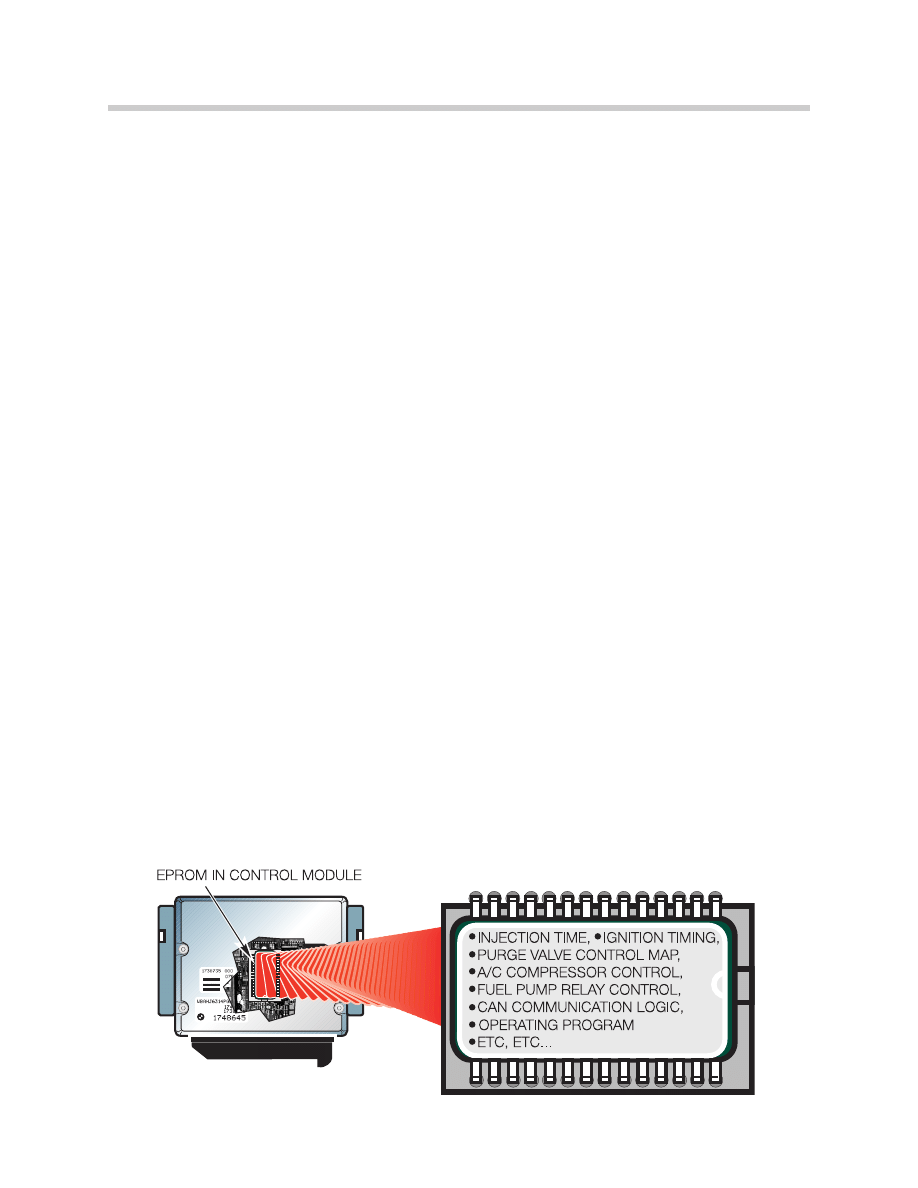
EPROM (Electrically Programmable Read Only Memory)
An EPROM is a computer memory chip that can be electrically programmed, however
this chip cannot be erased using normal means.
In order to erase data that is stored on the chip it must be removed from the device and
exposed to UV lighting for a specific time period. An EPROM has what is commonly
called a “window” on the top portion of the chip usually located underneath a protective
label, it is this area that must be exposed to UV light of a certain intensity for a specific
time period in order to erase the information stored on it.
BMW does not currently utilize EPROMS on current vehicles.
8
Coding & Programming
DME
DME
9
Coding & Programming
EEPROM (Electrically Erasable Programmable Read Only Memory)
An EEPROM is a computer memory chip that can be electrically programmed and
electrically erased, thereby not requiring the chip to be removed from the module or
exposed to light. In general this chip is not easily removable from the device it is
installed into (it is usually soldered in its place).
Since the entire process of programming and erasing is done electronically this device
is commonly referred to as “Flash Programmable”.
During the programming process the following type of information may be loaded into
the control module depending on the specific application or update that needs to be
installed:
• Characteristic Maps (Ex. Ignition, Injection, Purge Control, DSC Regulation, ...)
• Control Constants/ Operational Data
• Operational Program
• Control Module Identification Information (Ex. Hardware Number, Program Number,
Date of Modification, ...)
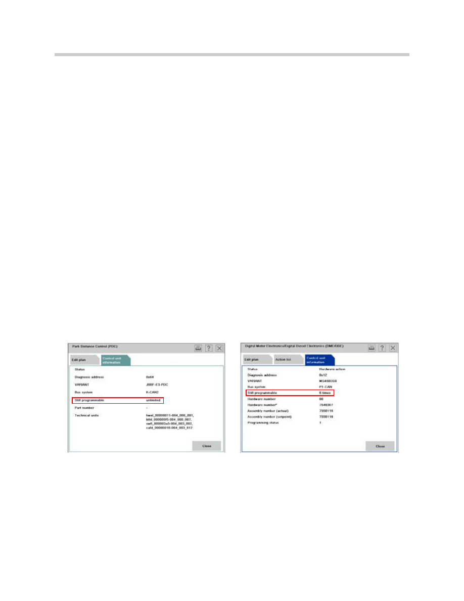
At this moment, there are modules with EEPROMS that can only be flash programmed
(“flashed”), 14 times total and others that have no limit. For the ones that do, if the
module has to be programmed a 15
th
time, the module has to be replaced.
Note: For more information on whether a control module can be programmed
or not, please refer to the Control Unit Information tab in ISTA P.
What is needed to Code and Program?
In order to code or program a vehicle or control in the workshop, specific equipment and
special software is required such as ISTA/P which must be connected to a network and
have the most current version installed. Having the latest version will allow ISTA/P to
update the required control modules to address customer concerns and implement ser-
vice solutions.

Complete Software Update Programming Procedures
(Five Pillars) + 1
There are constant improvements and enhancements to BMW products that are includ-
ed with each new software release. However, it is not BMW's policy to automatically
update vehicles with new software as it becomes available. This practice is time consum-
ing, costly, and may change the functionality of one or more systems; in most cases, it
offers no tangible benefit to the customer.
In situations where BMW identifies specific product issues, the fixes are integrated into
the diagnostic test plans, and/or are announced via an SIB. If the applicable test plans
have been completed, and the SIBs reviewed in TIS did not identify any fixes related to a
software update, there is no reason to believe that the latest version of vehicle software
will correct a customer's concern.
Before updating the vehicle's software, always verify that:
1. The latest available software release version has an Integration Level that is higher
than the vehicle's current software Integration Level. The vehicle's current software
Integration Level is shown when completing the Vehicle Test using ISTA or in the
Software tab in SAM, which is located in DCSnet, after the current key data is read.
The current software Integration Level will also display the corresponding Print Key
Data printout.
2. The vehicle's current Integration Level is not already equal to or greater than the
minimum Integration Level specified as needed in a corresponding SIB or repair
procedure. Refer to SI B09 07 07 for a cross-reference between Integration level
and Programming version.
Five Pillars for Programming a Vehicle
A vehicle must have its software updated if:
1. Programming was required after replacing a control module.
2. Programming was required, as outlined in an SIB, to address a specific product
issue, Service Action or Recall; and the vehicle's current Integration Level is lower
than what is specified as necessary.
3. A Programming Validation Code (GW Code) was provided at the end of a diagnostic
test plan.
4. Programming was recommended through a PuMA contact.
5. Programming was recommended by the Regional Technical Engineer (RTE).
Lastly, a vehicle may also be programmed because of:
1. Software updates caused by a "customer pay" conversion or retrofit.
Note: For more information please refer to SI B01 03 06.
10
Coding & Programming

11
Coding & Programming
Introduction
As part of an ongoing process to reduce the need for country, model and option specific
control modules, BMW utilizes a multi digit vehicle coding structure referred to as a
Central Coding Key (ZCS).
The Central Coding Key (ZCS) is a unique 37 digit code that contains specific model,
country variation and individual equipment/option information for a vehicle.
During the manufacturing process of a vehicle, the ZCS code is created to identify the
specific vehicle being built and to properly code the control modules installed during the
assembly process once the vehicle reaches the end of the line. To ensure that the ZCS
code can be retrieved once the vehicle leaves the factory it is stored in two control mod-
ules, the cluster and the EWS.
ZCS is often referred to as a “key” since it is able to automatically “unlock” or ”activate”
specific functions of a new control module or can be used to recode a used control
module to be compatible with the specific vehicle it has been installed into. With the
introduction of the E31 the ZCS information was used for the first time as a coding key
for replacement vehicle control modules, this ensured that the replacement modules
would be coded to the required specification of the vehicle.
These codeable modules have no limit as to the number of times that they can be
recoded.
GM 16430000P
SA
0000422005009CC0U
VN
000001E116K
Vehicle Coding Information

ZCS Structure
The 37 digit structure of the ZCS is subdivided
into three segments. The segments represent
specific information about the vehicle.
Each segment ends with a checksum “digit”.
A checksum is utilized by the coding software to
detect unacceptable/erroneous manually entered
coding information.
The information/digits of the ZCS code reflects the options installed in the vehicle and
should never be changed manually unless it is necessary for special recoding functions
such as:
• Canadian market vehicle being moved to the US
• Retrofit installation of an accessory system (ie. alarm or satellite radio)
For extreme cases; If a modification needs to be made to the ZCS structure and there is
no information available in a service bulletin then the Technical Hotline should be con-
tacted for assistance by submitting a PUMA case, requesting a modified ZCS code.
Each portion of the ZCS provides specific information regarding that vehicle:
GM (Grundmerkmale) - Identifies the “Basic Features” of the vehicle and contains
9 digits that are used to describe:
• Vehicle type (R50, R52, R53 ...)
• Specific body style of the vehicle (Convertible, Coupe ...)
• Country specific coding identification (US, UK, ECE ...)
• Unique equipment that affects the basics of the vehicle
(with sunroof, without sunroof, wheel size ...)
• Basic language variant (English, Spanish, German ...)
SA (Sonderausstattungs) - Identifies the “Special Equipment” of the vehicle and contains
17 digits that describe what features/functions are installed in
the vehicle, such as:
• Power Windows or Manual windows
• Power Door Locks or Manual Door Locks
• Power Sunroof or Manual Sunroof
• Power Convertible Top or Manual Convertible Top
• Satellite Pre-wire
The SA segment is configured to provide a total of 64 possible number combinations
(option groups) for all series vehicles worldwide. The information is modified whenever
a new component/accessory is added to the vehicle via a retrofit coding procedure.
12
Coding & Programming
GM 16430000P
SA
0000422005009CC0U
VN
000001E116K
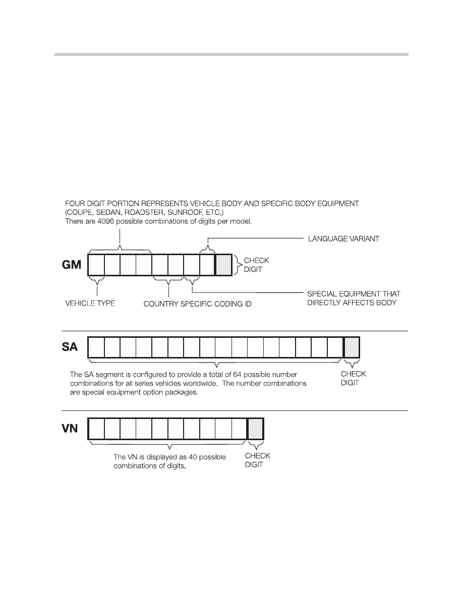
VN (Versionsnummer) - Identifies the “Version Number” of the vehicle and contains
11 digits that are used to describe:
• Series specific coding data that are not reflected in the GM
or SA segments. This includes, model year dependent data,
software and hardware versions of the control modules
installed, coding instructions, etc.
The VN is displayed as 40 possible combinations of digits. A deliberate change in the
VN will result in erroneous coding data being used when recoding a module or coding a
replacement module which will affect the proper operation of a control module(s) coded
with an incorrect VIN.
13
Coding & Programming
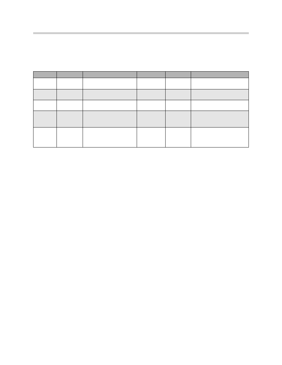
ZCS Stored Location in Vehicle
The ZCS is stored in the vehicle to simplify the coding procedures when a module needs
to be recoded or a replacement module needs to be coded. Depending on the vehicle,
the ZCS information is stored in the following locations:
* The E46 switched to a Vehicle Order (VO) data structure in 9/01.
The procedure to code control modules that utilize the ZCS information can be per-
formed via ISTA/P. Always reference service bulletins for information regarding the latest
coding version and any possible software errors.
When coding a ZCS codable control module the coding program automatically searches
the stored location, based on the VIN, and codes the selected module according to the
information provided in the ZCS code.
On later production vehicles the ZCS information began to be stored in two locations,
referred to as redundant data storage, this insures that the information is always available
in the event the primary device storing the data fails.
Note: On early production vehicles without redundant data storage, if the mod-
ule being coded or recoded is the module that stores the ZCS informa-
tion, then the vehicles ZCS information must be obtained from the label
located on the vehicle or electronically accessed from the module and
printed out then entered manually via the input screen on ISTA/P.
For vehicles with redundant data storage the coding of the module stor-
ing the data is performed automatically using the information stored in
the “back up” module.
14
Coding & Programming
Vehicle
Model
Module
Vehicle
Model
Module
E31
All
EKM
E39
All
Instrument Cluster/EWS
E32
All
Instrument Cluster
E38
All
Instrument Cluster/EWS
E34
All
Instrument Cluster
E46*
All
Instrument Cluster/LSZ
E36
318i/is
325i/is
M3
Instrument Cluster
E52
All
Instrument Cluster/LSZ
E36
318ti
Z3
EWS II
As of 9/98:
Instrument Cluster/EWS
E53
All
Instrument Cluster/LSZ
15
Coding & Programming
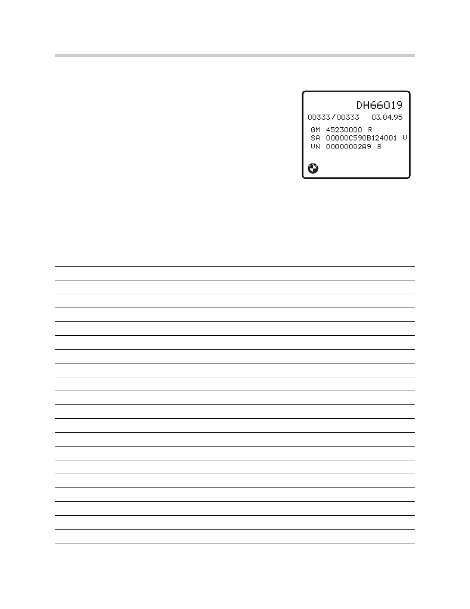
Accessing ZCS Information Label
On earlier production vehicles the ZCS label is affixed to the
vehicle in a specific location depending on the model:
• E36 - Under rear seat; center area or next to left send-
ing unit of fuel tank.
• Z3 Roadster - In Trunk; under carpet on floor, forward
of tool kit.
• E31/32/34 - In fuse box cover
• E38 - In E-Box cover
Note: As of 9/98 production the ZCS label was eliminated from the vehicle.
Some older vehicles will have identification labels containing an AM
segment, this information is not needed for coding or recoding a control
module on that vehicle.
NOTES
16
Coding & Programming
Vehicle Order
In 9/01 the ZCS vehicle data structure on the E46 was replaced with what is referred to
as the Vehicle Order (VO) or Fahrzeugauftrag (FA). The vehicle order structure is utilized
on all new models introduced/produced as of 9/01, such as E65/66, E60, E63/64, E83,
E85 etc. Models such as E36, E39, E52, and E53 produced after 9/01 continued to be
manufactured using the ZCS structure until production of the model is complete.
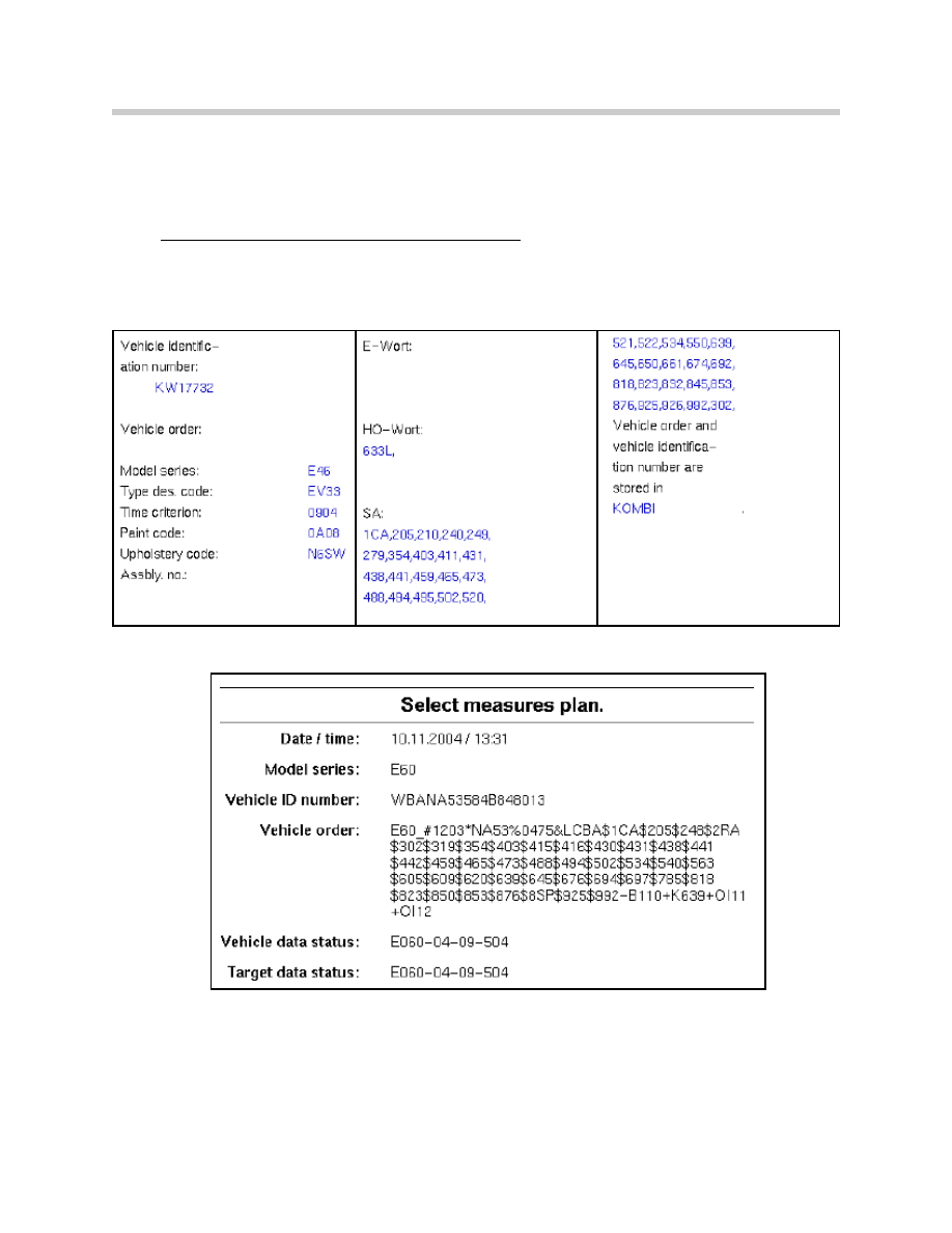
Vehicle Order for E46 as of 9/01 Production:
Vehicle Order for New Models as of 9/01 Introduction:

17
Coding & Programming
The vehicle order format contains information pertaining to the production of a specific
vehicle such as:
Series Type - E46, E65, E60, etc.
Time Criterion - Identifies date the options/hardware equipment available for installation
into the vehicle was standardized/”locked”. This information does not
refer to the production date of the vehicle. A problem with coding or
programming may occur if a module or option based on a newer or
older time criterion date is installed into the vehicle.
Model Code (Basic Type) - Base level from which the vehicle is “created/built”.
Paint Code - Identifies the color of the vehicle at time of production.
Upholstery Code - Identifies the type of upholstery installed in the vehicle at time of
production.
Assembly Number - Identifies the programmed part number for powertrain (Not used).
E-Wort - Identifies additions/options added to the vehicle that are not part of standard
SA codes/options.
HO-Wort - Identifies options installed at Center/Dealer using 3 digit option code
(Currently not used).
Installed Option/SA Codes - Listing of accessories & equipment options installed
in the vehicle.
The information contained in the vehicle order is used to identify the module(s)/system(s)
that are/should be installed in the vehicle and also what if any control modules need to be
updated if a new system/option is added or removed to/from the vehicle to ensure proper
compatibility with the devices installed in the vehicle. The information contained in the
vehicle order such as installed options, is modified whenever a new component (mod-
ule/system) is installed and coded to the vehicle. If the new component is not properly
coded to the vehicle the SA listing is not updated and problems can be encountered
whenever a measures plan for the vehicle is created, vehicle needs to be recoded or
VKM/Individualization functions are to be modified.
A listing of the components that need to be updated is provided whenever a measures
plan is generated.
18
Coding & Programming
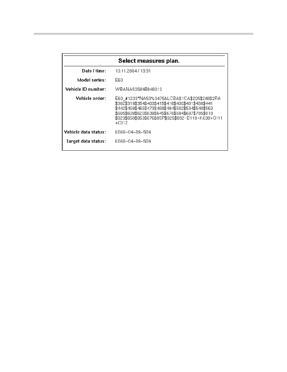
Example: Information contained in the VO of an E60
Series Type:
E60
Time Criterion:
Identified as 1203 indicates the date (month/year) that the list of
available options/hardware available for installation into the vehicle
was standardized/”locked”. Although the vehicle referenced was
produced in 6/04 the time criterion of 1203 is still valid and indi-
cates that no changes were made to the available option pack-
ages/hardware available for installation into that specific model
since 1203.
Model Code:
Identified as NA53 indicates the vehicle and engine type plus pro-
vides information pertaining to the country the vehicle was built for
(i.e. LH or RH drive). If an automatic transmission is installed it will
be considered an NA63, however the model code contained in the
VO will always reflect the base level which is a manual transmission
vehicle.
Paint Code:
Identified as 0475 indicates the color of the vehicle at time of pro-
duction.
Upholstery Code: Identified as LCBA indicates the type of upholstery installed in the
vehicle at time of production.
Installed Option/
SA Codes:
Listing of accessories & equipment options installed in the vehicle
1CA - Selection COP relevant vehicles
205 -Automatic transmission
248 - Steering Wheel Heating
2RA - LT/ALY wheels

19
Coding & Programming
An EEPROM is an Electrically Erasable Programmable Read Only Memory chip that
is soldered onto the circuit board of a control module. This signifies that programs &
data stored on the chip can be electrically erased and replaced with new/revised
programs or data.
In order to erase the data on the chip a short duration low level voltage/charge is applied
to a pin on the EEPROM and the stored data is erased, hence the name “Flash”. Once
the data is erased new data is loaded.
By using a this technology, control modules have the ability to be updated a total of
13 times before they need to be replaced.
Theoretically an EEPROM can be erased and reprogrammed more than 13 times,
BMW set the number to 13, since a point will be reached where the update being
installed may no longer be compatible with the hardware of the installed module which
could result in erroneous operation. If the program is not compatible with the hardware
version of the module, the program used to determine the correct update for the module
will indicate that the module will need to be replaced before the update can be per-
formed.
The reference to Flash programming is a result of the technology used to erase the
EEPROM prior to installing a new program and or data.
The utilization of EEPROMs started with Engine Management Systems and has
expanded into other control modules.
Determination Process for DME EEPROM
ISTA/P is used to determine the correct replacement part numbers (Control Module or
software update) to be installed.
For modules that utilize EEPROMs/Flash programming the determination process is
done automatically as part of determining a measures plan.
Control Modules Flash (EEPROM) Programming

20
Coding & Programming
Introduction
The intention of ISTA/P is to insure that whenever a module is updated or replaced it will
still be compatible with all the other modules installed in the vehicle. Since all of the
communication between the various modules installed in a vehicle is over a bus network
structure, it is very important that all of the installed modules be able to communicate
with each other without problems.
To ensure compatibility/seamless integration between control modules, ISTA/P reads out
the part numbers of all the control modules installed in the vehicle as well as the soft-
ware levels of the respective modules. The information from the various installed mod-
ules is then cross referenced against a “master reference list” to determine if a module(s)
needs to be updated and how this update will effect the other installed modules. Once
this cross reference process is started it can result in additional issues such as:
• If the software level in a selected module is updated will the hardware of the module
still be able to function correctly.
• If the software to be installed is not going to be compatible with the installed hard-
ware then the module will need to be replaced.
• If updated software is installed in the selected module will this have any impact on
any other installed modules and will they need to have the software updated or will
the hardware need to be updated in additional modules in order to install the
revised software.
Example: A desktop computer originally built with a Pentium I, 75 MHz processor
using Windows 95 is not able to operate using Windows 2000. In order to
operate with Windows 2000 this old desktop computer needs to upgraded
with new hardware. However, a desktop computer designed to operate with
Windows 2000 can be updated to Windows XP without having to upgrade
the hardware of the computer.
Coding & Programming
21
Coding & Programming
All hardware devices that utilize software/programs to operate can only have the installed
software updated a certain number of times before the operating capacity of the installed
hardware is exceeded and no longer compatible, this results in the device no longer being
able to function. In order for these devices to continue to operate the installed hard-
ware/control modules will need to be updated, which is what happens in our vehicles or
desktop computers over time.
Specific information pertaining to coding and programming with ISTA/P are provided in
SI B 09 05 01.
Integration Levels
All new models produced as of the E65 have a minimum allowable software level, based
on production date, which is referred to as an integration level or data status. The inte-
gration level defines the software level that all the control modules installed into a particu-
lar model, at time of production, must be at in order to ensure compatibility. Once an
integration level for a specific production period is defined/“locked”, the modules installed
in those vehicles can not be updated beyond that level.
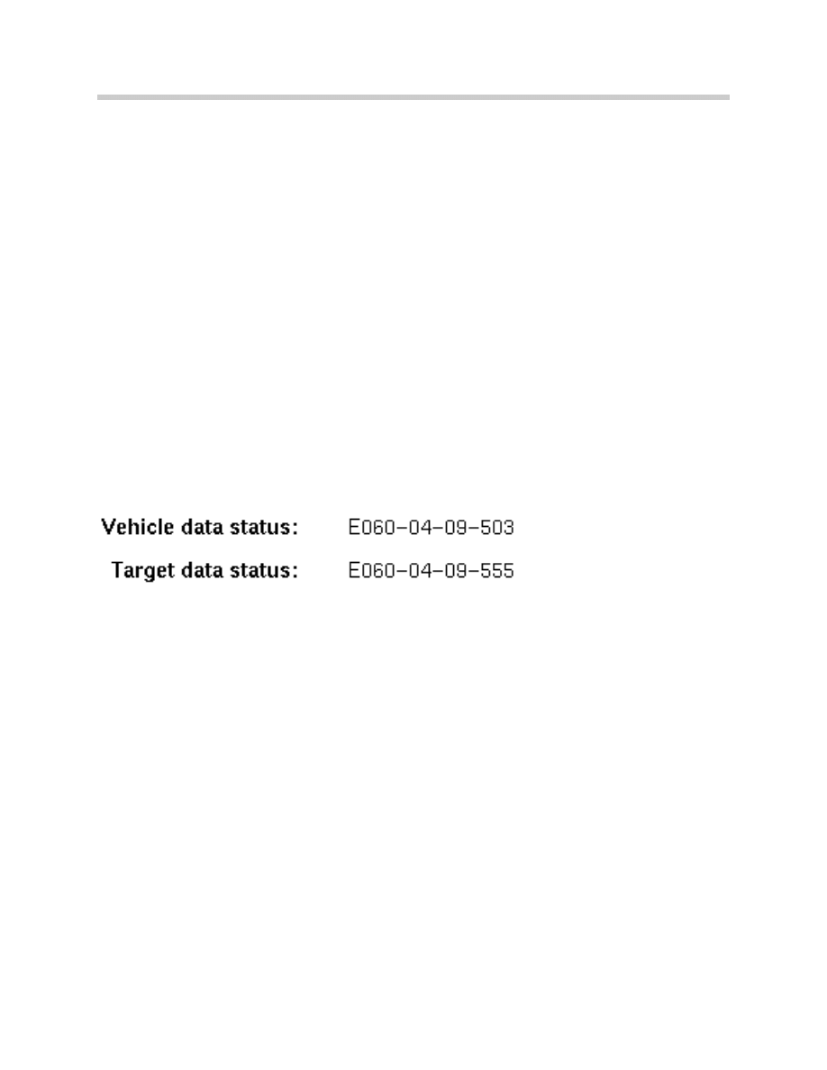
The Integration level or data status for vehicles equipped with a most bus is provided in
the “Status report” or “Measures plan” as shown below.
If the vehicle data status and target data status are not the same, this indicates that some
of the installed control modules need to be updated to bring the vehicle up to the latest
level.
If the software levels were not locked it would be quite complex to track all software and
hardware variations for all models through all production ranges. It would be extremely
difficult to determine what software and hardware level is compatible with each module
installed in a specific vehicle(s) and exactly what needs to be updated if one module is
updated or replaced, therefore a limit or locked point must be define for specific produc-
tion periods by model.
Example: MY2002 vehicles can not be programmed with software that is assigned to
MY2003 vehicles since the defined integration level for each Model Year is
different. Similarly Windows 2000 can not be installed & operated on a com-
puter originally developed to run with Windows 95.
Information contained in this module is for reference as a user guide, more detailed infor-
mation can be obtained from the respective Service Information Bulletins
SI B09 05 01 & SI B09 03 98.

22
Coding & Programming
NOTES
PAGE
Document Outline
- Main Menu
- 01_Introduction to BMW
- 02_Features and Technology
- 03_Information Resources
- 04 Workshop Equipment
- 04a_ISIS.pdf
- 04b_ISID.pdf
- 04c_ICOM
- 04d_IMIB
- 04e_ISAP
- 05 Workshop Applications
- 05a_ISTA
- 05b_IMIB
- 05c_Understanding Diagnostics
- 05d_Coding and Programming
- 05e_ISTA-Programming
- 06_Service and Maintenance
- 07_PuMA
- 08_Basic Diagnostic Certification
Wyszukiwarka
Podobne podstrony:
Ada 95 A guide for C and C programmers S Johnston
coding and cryptography 6Y62KKTQLITJVMP5343FZ6VRTKBB32IB4YQTH5I
Embedded Systems Building and Programming Embedded Devices
Instruction of connection and programming of OSCAR N PLUS OBDCAN controller
How to Design Programs An Introduction to Computing and Programming Matthias Felleisen
Embedded Systems Building and Programming Embedded Devices
Classroom types Programs and programming languages
Instruction of connection and programming of OSCAR N MINI controller
QGIS 1 4 0 Coding and Compilation Guide
Programming Survey Of Genetic Algorithms And Genetic Programming
A Comparison between Genetic Algorithms and Evolutionary Programming based on Cutting Stock Problem
instalacja i plug and play, java, javascript, oprogramowanie biurowe, programowanie, programowanie 2
Programming and Documentation Pad
SHSBC377 THE CLASSIFICATION AND GRADATION PROGRAM
Library Science Programs and Continuing Education Opportunities
M Kaufmann Programming Cameras and Pan tilts With DirectX and Java fly (2)
więcej podobnych podstron