1.Dane wyjściowe.
1.1. Parametry geotechniczne gruntów (na podstawie (Tab.1, Rys3,4,5 PN-81/B-03020) )
|
|
|
|
|
|
|
2,65 |
1,70 |
31 |
0 |
5 |
|
2,65 |
1,65 |
32 |
0 |
6 |
|
2,65 |
1,75 |
39 |
0 |
4 |
|
|
|
|
|
|
|
|
0,89 |
1,51 |
27,59 |
- |
1,2 |
2,22 |
|
0,9 |
1,49 |
28,8 |
- |
1,2 |
2,25 |
|
0,89 |
1,56 |
34,71 |
- |
1,2 |
2,1 |
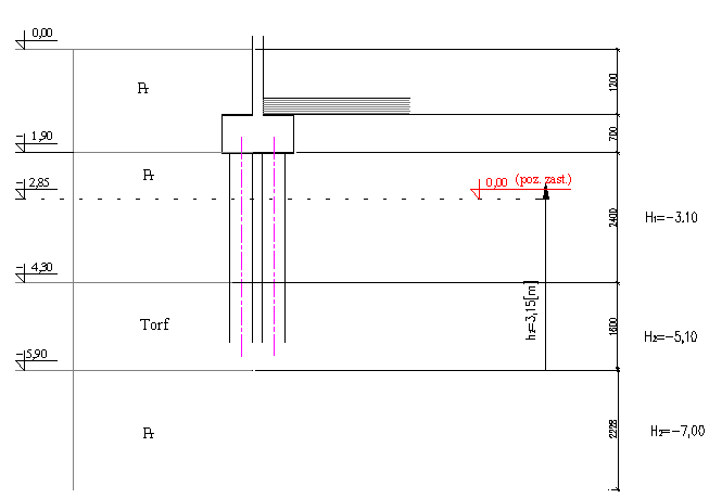
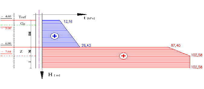
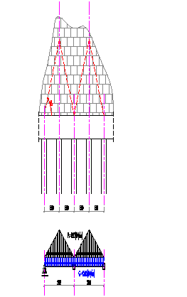
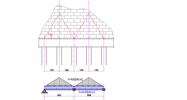
Warunki gruntowo wodne ( przekrój geotechniczny)
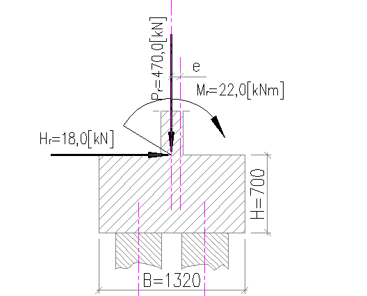
Sprawdzenie mimośrodu obciążenia.
2.1. Zestawienie obciążeń.
![]()
![]()
![]()
![]()
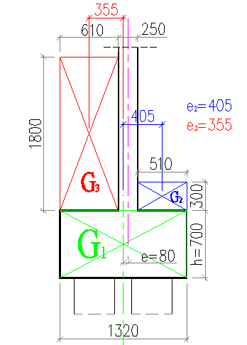
Wyznaczenie mimośrodu od obciążeń stałych.....(

)
![]()
![]()
![]()
Przyjęto przesunięcie środka ciężkości osi ściany o ![]()
![]()
.
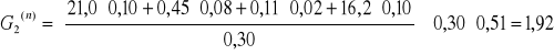
Obciążenia....(na 1

dł. ławy!)
ciężar oczepu
![]()
![]()
![]()
![]()
![]()
![]()
ciężar posadzki
wylewka cem.
![]()
![]()
![]()
![]()
styropian
![]()
![]()
![]()
![]()
2 × papa .
![]()
![]()
![]()
![]()
piasek
![]()
![]()
![]()
![]()
![]()
![]()
![]()
ciężar gruntu
![]()
![]()
Mimośród
![]()
![]()
![]()
Przy tak małym mimośrodzie można założyć, że pale będą obciążone równomiernie!
3.Obliczenie nośności pojedynczego pala (![]()
)
![]()
((2)PN-83/B-02482)
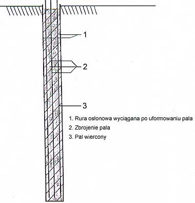
3.1. Przyjęcie typu pali ( Pale wiercone)
3.2. Wyznaczenie jednostkowej, obliczeniowej wytrzymałości gruntu pod podstawą pala (![]()
)
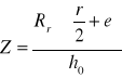
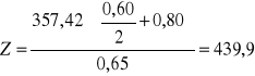
a) poziom zastępczy
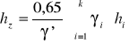
(str.130 SKRYPT'97)
![]()
- wartość charakterystyczna ciężaru obj.
gruntu nośnego z uwzględnieniem wyporu
wody (dla ![]()
![]()
![]()
![]()
)
![]()
-wartość charakterystyczna ciężaru gruntu
z uwzględnieniem wyporu wody w
warstwie „i” zalegającej nad stropem
gruntu nośnego( dla ![]()
![]()
![]()
![]()
dla ![]()
![]()
![]()
![]()
)
![]()
![]()
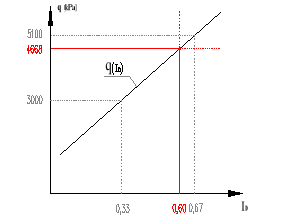
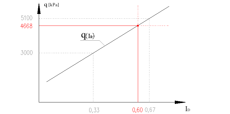
b) określenie wartości ![]()
od ![]()
(Tab.1 PN-83/B-02482)
![]()
((4) PN-83/B-02482)
Zakładamy że pale będą kończyć się
w warstwie żwiru -grunt niespoisty
(w naszym przypadku ![]()
) i
dla takich parametrów wyznaczyliśmy
![]()
![]()
, ![]()
![]()
![]()
![]()
ale teraz musimy uwzględnić średnicę pali!
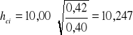
c) określenie wartości ![]()
od ![]()
wyznaczenie głębokości krytycznej

(dla pali wierconych:
)
dla ![]()

![]()
((7)PN-83/B-02482)
![]()
- głębokość krytyczna (![]()
![]()
)
![]()
- wyjściowa średnica podstawy pala
(![]()
![]()
)
![]()
![]()
![]()
3.4. Wyznaczenie jednostkowych wartości wytrzymałości pobocznicy pala.
a)określenie wartości ![]()
od ![]()
,![]()
(Tab.2 PN-83/B-02482)
a)określenie wartości ![]()
od H
3.5. Wyznaczenie długości pala
ciężar pala
![]()
![]()
![]()
![]()
![]()
![]()
![]()
![]()
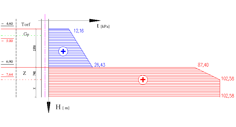
wypadkowa tarcia negatywnego gruntu (

)
![]()
![]()
![]()
![]()
![]()
- współczynnik technologiczny zależny od
rodzaju gruntu i typu pali(technologii
wykonania) (Tab.4 PN-83/B-02482)
W naszym przypadku mamy do czynienia z palmi
wierconymi w rurach obsadowych wyciąganych.
dla 1:![]()
(![]()
)![]()
![]()
dla 2: ![]()
![]()
![]()
![]()
![]()
![]()
![]()
![]()
![]()
![]()
![]()
![]()
![]()
długość pala (

)
![]()
(str.147 SKRYPT'97)
![]()
![]()
![]()
![]()
(patrz p.3.2.b ) ![]()
(dla żwiru)
![]()
(![]()
)![]()
![]()
![]()
(![]()
) ![]()
![]()
![]()
(![]()
) ![]()
![]()
![]()
![]()
![]()
![]()
![]()
![]()
![]()
![]()
![]()
![]()
![]()
![]()
![]()
![]()
![]()
![]()
![]()
![]()
![]()
![]()
![]()
![]()
![]()
![]()
![]()
![]()
![]()
![]()
(patrz p.2.3.)
![]()
![]()
![]()
![]()
![]()
![]()
![]()
![]()
![]()
![]()
![]()
![]()
Przyjęto ![]()
![]()
![]()
długość pali ![]()
![]()
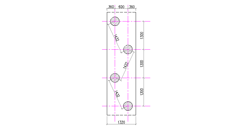
Pal w grupie.
![]()
((11) PN-83/B-02482)
![]()
- promień strefy naprężeń w gruntach
![]()
- średnica pala (![]()
![]()
)
![]()
- grubość warstwy tego samego
![]()
- kąt rozchodzenia naprężeń w gruncie (Tab.7PN-83/B-02482)
W przypadku a) naprężenia zachodzą na siebie i musielibyśmy zredukować w pewnym stopniu nośność pala! Ale istnie możliwość wykonywania pali pod kątem ,dla tego propozycją na rozwiązanie problemu zachodzenia naprężń jest wykonać wiercenie tych pali pod kątem ![]()
!
5.Zbrojenie ławy
5.1. Zbrojenie poprzeczne ławy
![]()
![]()
![]()
![]()
![]()
Przyjęto w obrębie ![]()
![]()
![]()
a na pozostałych odcinkach po![]()
.
5.2. Zbrojenie podłużne ławy
obciążenia
-ciężar własny ławy ,ciężar gruntu nad ławą , ciężar posadzki (patrz p.2.3.)
![]()
![]()
-ciężar pryzmy trójkątnej muru(![]()
)
![]()
![]()
![]()
![]()
![]()
![]()
b) wartości momentów
-na podporze (nad palami)
![]()
![]()
-w przęśle pośrednim
![]()
![]()
-w przęśle skrajnym
![]()
![]()
c) przyjęcie liczby potrzebnego zbrojenia
Z obliczeń otrzymaliśmy przekrój mniejszy od minimalnego zbrojenia ![]()
, przyjęto więc zbrojenie min!
![]()
![]()
Przyjęto ![]()
10
1
Wyszukiwarka
Podobne podstrony:
3935
3935
3935
3935
3935
3935
3935
3935
3935
200412 3935
3935
3935
3935
org lett 3 3935 salvinorin c
więcej podobnych podstron