led sequencer night rider

L.E.D. Seąuencer - MgM IEM©ff
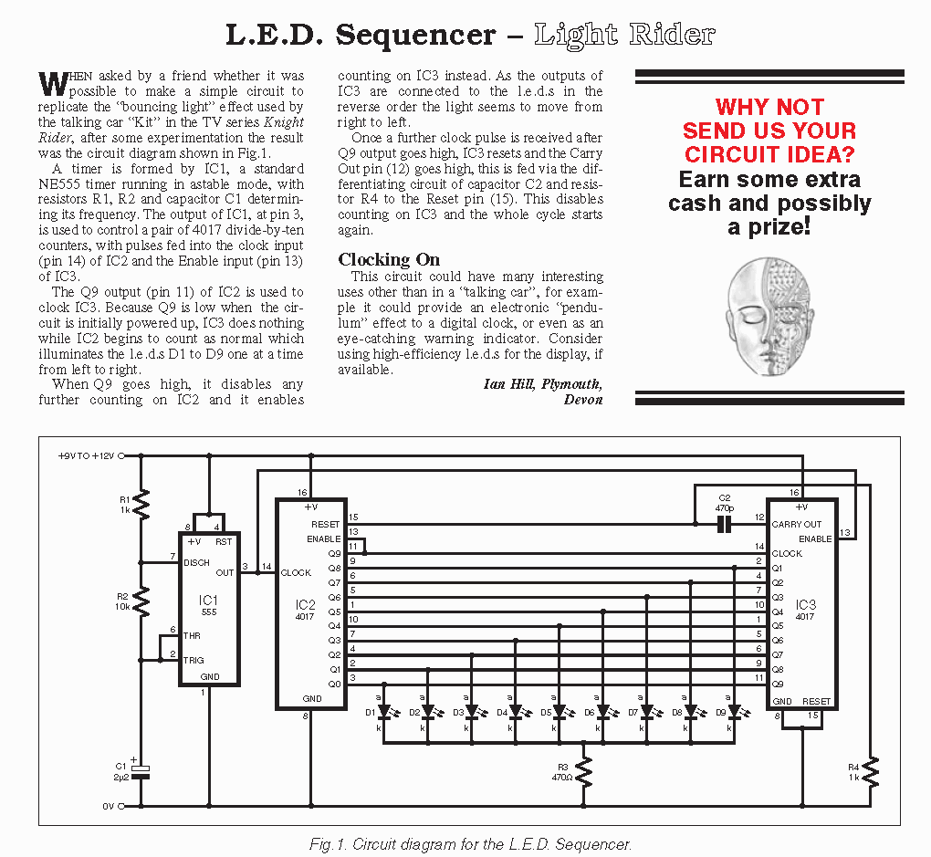
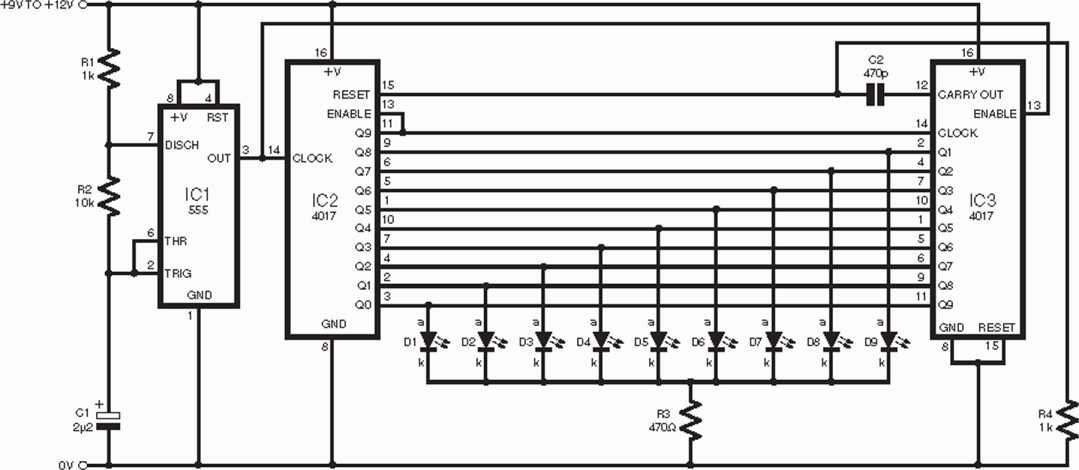
W hen asked by a friend whether it was possible to make a simple Circuit to replicate the “bouncing light” effect used by the talking car “Kit” in the TV series Knight Rider, after some experimentation the result was the Circuit diagram shown in Fig.l.
A timer is formęd by 1C1, a standard NE555 timer running in astable modę, with resistors Rl, R2 and capacitor Cl determin-ing its freąuency. The output of IC1, at pin 3, is used to contro 1 a pair of 4017 divide-by-ten counters, with pulses fed into the clock input (pin 14) of IC2 and the Enable input (pin 13) of IC3.
The Q9 output (pin 11) of 1C2 is used to clock IC3. Because Q9 is Iow when the Circuit is initially p owe red up, IC3 does nothing while IC2 begins to count as nor mai which illuminates the l.e.d.s Dl to D9 one at atime from left to right.
When Q9 go es high, it disables any further counting on IC2 and it enables counting on 1C3 instead. As the outputs of 1C3 are connected to the l.e.d.s in the reverse order the light seems to move from right to left.
Once a further clock pulse is received after Q9 output goes high, 1C3 resets and the Carry Out pin (12) goes high, this is fed via the dif-ferentiating Circuit of capacitor C2 and resis-tor R4 to the Reset pin (15). This disables counting on IC3 and the whole cycle starts again.
Clocking On
This Circuit could have many interesting uses other than in a 'talking car”, for example it could provide an electronic “pendu-lum” effect to a digital clock, or even as an eye-catching waming indicator. Consider using high-efficiency l.e.d.s for the display, if available.
łan HiU, Plymouth, Devoti
WHY NOT SEND US YOUR CIRCUIT IDEA? Earn some extra cash and possibly a prize!


Fig. 1. Circuit diagram for the L.E.D. Seąuencer.
Wyszukiwarka
Podobne podstrony:
led sequencer night rider L.E.D. Seąuencer - MgM IEM©ff W hen asked by a friend whether it was possi
Image2148 BSBRHHHHRmTes^i "•f bp i uznać/ za rozproszone, a energia pstyczl 1* przez przegro
skanuj0065(1) We were walking across Greenfield Park. It was twelve o clock at night. The park was e
07 (79) &) f‘ y" SOOtjri- J>fj) tĄ * lypu T JM . fy3 £5 ąM TO .
night im day * -5 IE +5 IE - black linę, HR slowing -white linę, * p<0.05 as compared to INI
United Poster by thagerott one neart. one moutn. to glorify Go areawide night of youth joining toget
PICT0407 o / - r*—‘T* -~F ((monnenvtr ^iętAo- «vfM^)-U>jZ<łuaca^of <*a^*eava. ^7ryvtiZr6 to
07 (79) &) f‘ y" SOOtjri- J>fj) tĄ * lypu T JM . fy3 £5 ąM TO .
Database Backup and Recovery Concepts To back up your database mcans to make copies of yourdata file
07 (79) &) f‘ y" SOOtjri- J>fj) tĄ * lypu T JM . fy3 £5 ąM TO .
DSCN6492 T4. * »*f«**4, otytr**. do «t- p*U<»fc&. cUcć^K,it^cA- & t r%*^) łb.l - 0iU(A^bw
0 »f rcM, i/ ^ępCKOJ^f ~op i c*;<y > vc-&fpjpf cu jcy pryy>^ r ‘ TO? V-* ■
Obraz (85) 34 Phonology and the sequence within the nonmanual signal cannot bc reversed. It is not p
A GHOSTLY NIGHT It was a moonlight night in November, wlien tlie very shadows seemed turned to ghost
więcej podobnych podstron