29

(5)
w
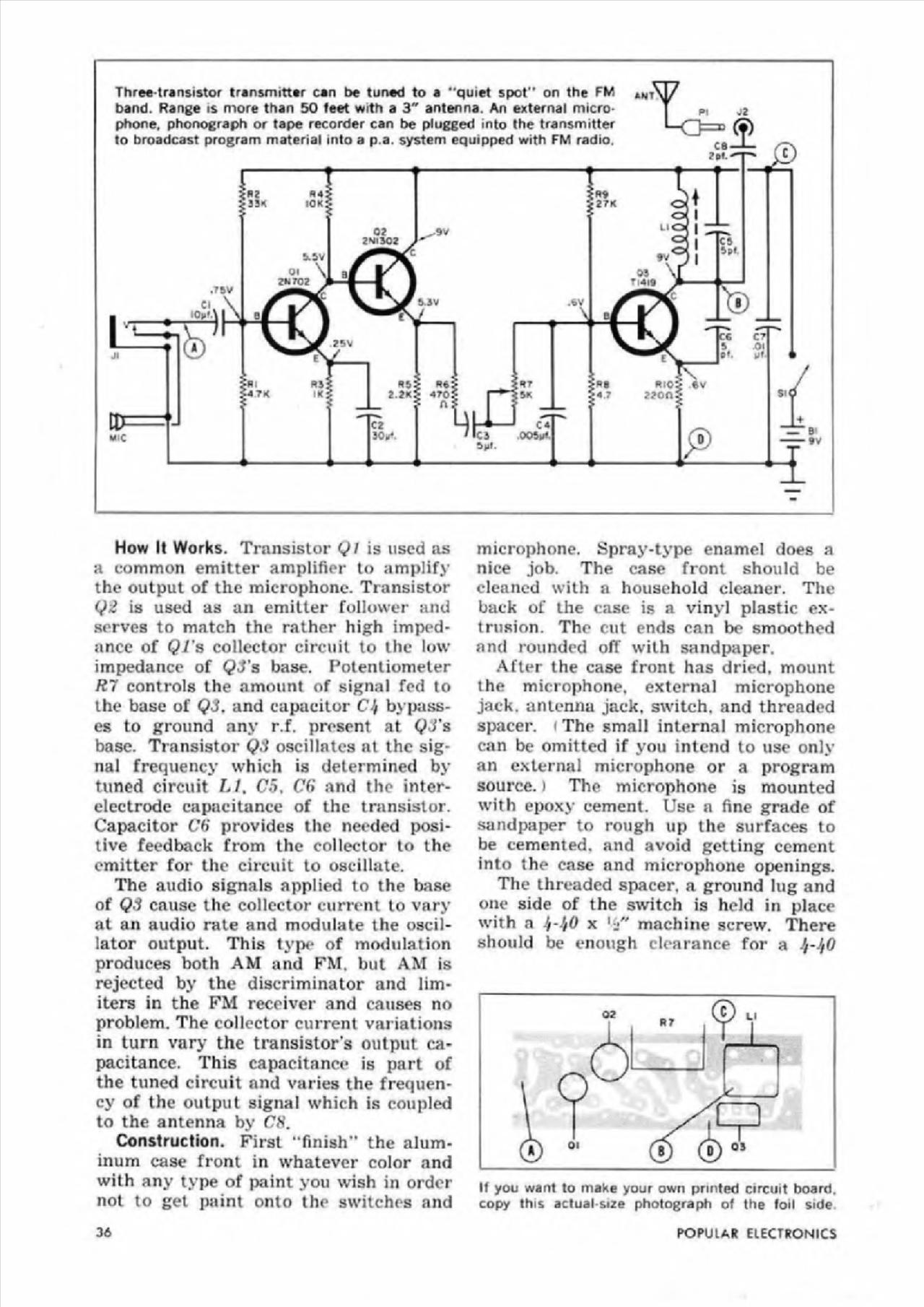
Thre€*tr«nsi5tor transmitttr can be tuned to a *'quiet spot" on the FM band. Rangę is morę than 50 feet with a 3" antenna. An external micro-pbone, phonograph or tape recorder can be plugged into the transmitter to broadcast program materiał into a p a. system eqaipped with FM radio.
AKT
p\

— B
MIC
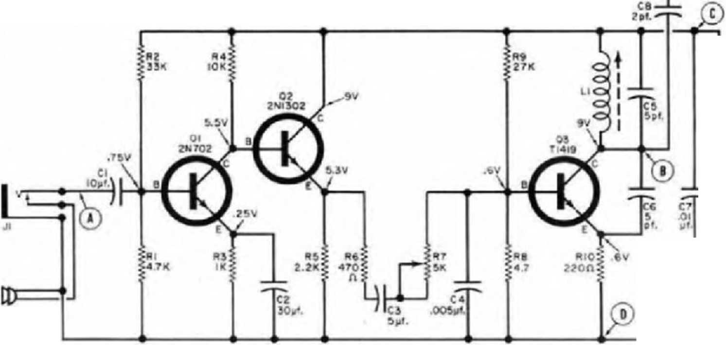
How It Works. Transistor Ql is uscd as a common emitter amplifier to amplify the output of the microphone. Transistor Q2 is used as an emitter follower and serves to match the rather high imped-ance of Ql's colleetor Circuit to the Iow impedance of QJ’s base. Potentiometer R7 Controls the nmount of signal fed to the base of Q3. and capacitor C-'/ bypass-es to ground any r.f. present at (J3's base. Transistor QS oscillates at the signal frequency which is determined by tuned Circuit LI. C5. Cd and the inter-electrode capacitance of the transistor. Capacitor Cd provides the needed posi-tive feedback from the colleetor to the emitter for the Circuit to oscillate.
The audio signals npplied to the base of Q1 cause the colleetor current to vary at an audio ratę and modulate the oscil-lator output. This type of modulation produces both AM and FM. but AM is rejected by the discriminator and lim* iters in the FM recciver and causes no problem. The colleetor current vai iations in turn vary the transistor's output capacitance. This capacitance is part of the tuned Circuit and varies the frequen-cy of the output signal which is coupled to the antenna by CS.
Construction. First "finish” the alum-inum case front in whatevcr color and with any type of paint you wish in order not to get paint onto the switches and microphone. Spray-type enamel does a nice job. The case front should be elenned with a houschold cleaner. The back of the case is a vinyl piastic ex-trusion. The cut ends can be smoothed and rounded olT with sandpaper.
After the case front has dried. mount the microphone. external microphone jack. antenna jack. switch. and threaded spacer, i The smali internal microphone can be omitted if you intend to usc only an exlernal microphone or a program source.» The microphone is mounted with epoxy cement. Use n fine grade of sandpaper to rongh up the surfaces to be cemented. and avoid getting cement into the case and microphone openings.
The threaded spacer, a ground lug and one side of the switch is held in place with a If-hO x 1 machinę screw. There should be enough clearance for a

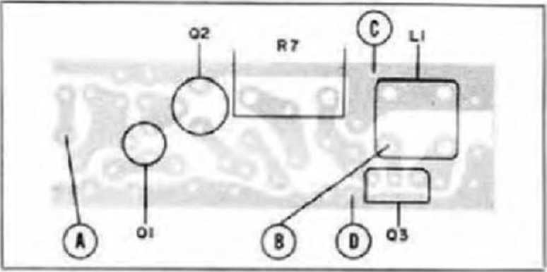
If you want to make your own printed Circuit board. copy this actual size photograph of the foil side
36
POPULAR ELECTRONICS
Wyszukiwarka
Podobne podstrony:
FIELD INSTRUMENTS IN MEASUREMENT SYSTEMS Level transmitters can be xnnected to the MultiCONT prxess
Introduction in Western Poland can be stimulated to a great extent by the significant growth potenti
10385 skanuj0024 (125) 2.* What can be done to prevent young people from using drugs? 3.
00027 ?6ad09812700ed54e35de4f20e2a7ad 26 Molnau The SPR procedurę can be applied to the fuli rangę
00070 fb165febe7867857bf3f5a54487a5b 69 Adaptiye Hierarchical Bayesian Kalman Filtering this can b
00102 B2805d720a3f852501694e34fead415 101 The OCAP seldom-used terminators can be moved to the end
Download Geometria del piano PDF eBooks Free Online, which can be sent to your customers and clients
of the people mentioned above marks the thesis as unsatisfactory (D),Chancellor decides if a student
C..A. Mascardi (Orał discussion) Few comments can be added to the contributions by Martinetti and Di
a distinctive colour tint can be applied to the erosion surface. This is better restricted to elear
The main disadvantages of using a Computer is that staring at a screen for long periods can be harmf
Gremlins (3) Grtmlkn óo not exntf Tbis card can be used to remove the Aclion token łrom any Computer
hammer of thor This mystic artifact can act once per tum. Its action can be used to increase the Pow
A closer look at the HP 495/C s flipdown keyboard. Unlike most Computer keyboardst it can be used to
C..A. Mascardi (Orał discussion) Few comments can be added to the contributions by Martinetti and Di
więcej podobnych podstron