Metex800 Digitalis Multimeter
1. INTRODUCTION
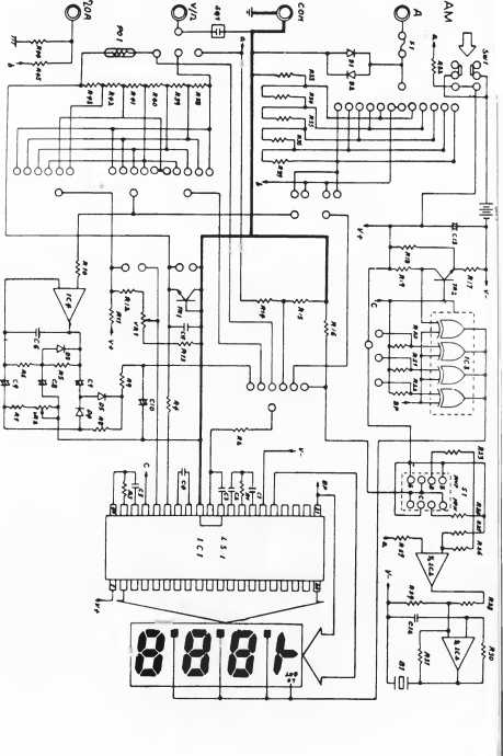
This instrument is a compact, rugged, battery operated, handheld 31/? digit multimeter for measuring DC and AC voltage, DC and AC current, Resistance and Diodę, for testing Audible continuity and transistor hFE. The Dual-slope A-D Converter uses C-MOS technology for auto-Zeroing, polarity selection and over-range indication. Ful! overload protection is provided.
It is an ideał instrument for use in the field, laboratory, workshop, hobby and home applications.
2. FEATURES
* Push-button ON-OFF power switch.
* Single 30 position easy to use rotary switch for FUNCTION and RANGĘ selection.
* 0.5" high contrast LCD.
* Automatic overrange indication with the “1” displayed.
* Automatic polarity indication on DC ranges.
* Ali ranges fully protected plus Automatic “ZERO” of all ranges without short Circuit except 200 ohm Rangę which shows “000 or 001
* High Surge Voltage protection 1.5 KV-3 KV.
* Diodę testing with 1 mA fixed current.
* Audible Continuity Test.
* Transistor hFE Test.
3. SPECIFICATIONS
Accuracies are ± (% reading -f No. of digits) Guranteed for 1 year, 23°C ± 5°C, less than 75% RH. DC Voltage
|
Rangę |
Accuracy |
Resolution |
|
200 mV |
100 mV | |
|
2 V |
1 mV | |
|
20 V |
±0.5%, of rdg +1 digit |
10 mV |
|
200 V |
100 mV | |
|
1000 V |
1 V | |
|
pedance: 10 M ohm on all ranges. Overload Protection: tage |
1000V dc or peak a< | |
|
Rangę |
Accuracy |
Resolution |
|
200 mV |
±1.2%, of rdg +3 digits |
100 |
|
2 V |
1 mV | |
|
20 V |
±0.8%, of rdgv+3 digits |
10 mV |
|
200 V |
100 mV | |
|
700 V |
±1 2%, of rdg +3 digits |
1 V |
Input impedance:< 10Mohm in parallel with>50PF (ac coupled).
Frequency Rangę. 40 Hz to 1 kHz.
Overload Protection 750V rms or 1000V peak continuous on ac ranges,
except 200 mV ac ranges (15 seconds maximum above 300V rms). Indication Average (rms of sine wave).
DC Current
|
Rangę |
Accuracy |
Resolution |
|
200 MA |
±0.5%, of rdg +1 digit |
0.1 MA |
|
2 mA |
1 fiA | |
|
20 mA |
10 [iA | |
|
200 mA |
±1.2%, of rdg +1 digit |
100 fiA |
|
2 A |
1 mA | |
|
20 A , 20MA |
±2.0%, of rdg ±5 digits |
10 mA ,10 nA |
Overload Protection: 2A/250N/ fuse (20A rangę unfused ). Maximum Input Current: 20A (up to 60 seconds). Measuring Voltage Drop: 200 mV.
|
Rangę |
Accuracy |
Resolution |
|
200 |
±1.0%, of rdg +3 digits |
0.1 ma |
|
2 mA |
1 ma | |
|
20 mA |
10 mA | |
|
200 mA |
±1 8%, of rdg +3 digits |
100 ma |
|
2 A |
1 mA | |
|
20 A . 20mA |
±3.0%, of rdg ±7 digits |
10 mA, 1 0 nA |
Overload Protection: 2JA/250V fuse (20 A rangę unfused ). Maximum Input Current: 20 A (up to 60 seconds). Frequency Rangę. 40 Hz to 1 k Hz Indication. Average (rms of sine wave)
Measuring Voltage Drop. 200 rnV
|
Rangę |
Accuracy |
Resolution |
|
200 ohm |
±0.5%, of rdg ±3 digits |
0.1 ohm |
|
2 K ohm |
±0.5%, of rdg ±1 digit |
1 ohm |
|
20 K ohm |
10 ohm | |
|
200 K ohm |
100 ohm | |
|
2 M ohm |
1 K ohm | |
|
20 M ohm |
±1.0%, of rdg +2 digits |
10 K ohm |
Overload Protection: 500V dc/ac rms on all ranges,
except 200Q rangę (200V dc/ac rms). Open Circuit Voltage: Less than 700 mV.
Relative Humidity: 0 to 75%, 0°C to 35°C on 2 MQ, 20 MQ 0 to 90%, 0°C to 35°C on all other ranges. 0 to 70%, 35°C to 50°C.
|
Rangę |
Description |
Test Conditiom |
|
f) -w- |
Display read approximate forward voltage of diodę |
Foward DC current approx imatelyimA Reversed DC yoltage approximately 2.8 Volts |
|
-w- |
Built-ln buzzer sounds if conductance is less than approximately 30Q |
Open Circuit Voltage approximately 2.8 Volts |
Transistor hFE Test
|
Rangę |
Description |
Test Condition |
|
hFE |
Display read approximate hFE value (0-1000) of transistor under test (ALL TYPE) |
Base Current approx 10.pA VCEapproximately 2 8 Volts. |
4. GENERAL CHARACTERISTICS
Maximum Display Indication Method Measuring Method Overrange Indication Maximum common modę voltage Reading ratę time
Temperaturę for guaranteed accuracy* : Temperaturę Ranges
Power Supply
Low Battery Indication
Size
Weight
Accessories
1999 counts (3l/z digits) with automatic polarity indication LCD display
Dual-Slope integration A-D converter system.
“1” Figurę only in the display.
500V dc/ac rms.
2-3 reading per sec (approximate).
23°C ±5°C.
Operating 0°C to 40°C, 32°F to 104°F.
Storage —10°C to 50°C, 14°F to 122°F/
One 9-volt battery (NEDA 1604. 6F22 TYPE or equivalent). LO BAT or BAT on theleft cf display.
88W X 172D X 36H m/m.
340g (including 9 volt batteries).
Operating manuał, 9V Battery (Zinc-Carbon TYPE).
Set of test leads, Spare fuse (2A/250N/ fast blow TYPE), and Carrying case.
5. OPERATION
PRELIMINARY NOTĘ
1. Check the 9-volt battery by setting the ON-OFF switch to ON If the battery is weak, a “LO BAT” or “BAT” sign will appear on the left of the display.
if this does not appear on the display, proceed as below. See MAINTENANCE if the battery has to be replaced
2. The mark, or sign, A next to the test lead jacks, is for warning that the input voltage or current should not exceed the indicated values.
This is to prevent demage to the internal circuitry.
3. The function switch should be set to the rangę which you want to test before operation
5-1 DC Voltage Measurement
1. Connect the BLACK test lead to the COM jack and the RED test lead to the V/Q jack.
2. Set the FUNCTION switch to the DC V rangę to be used and connect the test leads across the source or load under measurement .see Fig 5-1.
The polarity of the RED lead connection will be indicated at the same time as the voltage.
Notę ’ 1 2. 3. 4
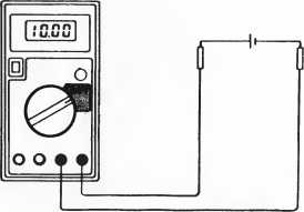
Fig. 5-1 DC Voltage measurement
If the voltage rangę is not known beforehand set the FUNCTION switch to the highest rangę and work down.
When only the figurę "1 ” is displayed, overrange is being indicated and the FUNCTION switch must be set to a higher rangę.
/\f Do not apply morę than 1000V to the input. Indication is possible at higher voltages but there is danger of damaging the internal circuitry.
Use extreme caution to avoid contact with high tension circuits when measuring high voltage.
. Connect the BLACK test lead to the COM jack and the RED test lead to the V/Q jack.
. Set FUNCTION switch to the AC V rangę to be used, and connect the test leads across the source or load under measurement. See Fig. 5-2.
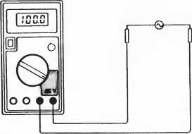
Fig. 5-2 AC Voltage measurement.
Notę :
See DC Voltage measurement Notę 1.2.
AL : do not apply morę than 700V rms to the input Indication is possiblc at higher voltages but there is danger of damaging the internai circuitry.
Use extreme caution to avoid contact with high tension circuits when measuring high voltage.
1. Connect the BLACK test lead to the COM jack and the RED test lead to the A jack for a Max-imum of 2A. For a maximum of 20A move the red test lead to the 20 A jack.
2. Set the FUNCTION switch to the DC A rangę to be used and connect the test leads in series with the load under measurement see Fig. 5-3.
The polarity at the RED test lead connection will be indicated at the same time as the current.
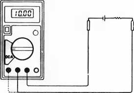
Fig. 5-3 DC Current measurement
Notę : 1. If the current rangę is not known beforehand. set the FUNCTION switch tothe highest rangę and work down.
2. When only the figurę “1 ” is displayed overrange is being indicated and the FUNCTION switch must be set at higher rangę.
3. /a The Maximum input current is 2A, or 20A depending upon the jack used. Excessive current will blow the fuse which must be repiaced. The 20 A Rangę is not protected by a fuse. The fuse rating should not be over 2A, to prevent damage to the internal circuitry.
4 The Maximum terminal voltage drop is 200 mV
5-4 AC Current Measurement
1. Connect the BLACK test lead to the COM jack and the RED test lead to the A jack, for a max-imum of 2A
For a maximum of 20A move the RED test lead to the 20 A jack.
2. Set the FUNCTION switch to the AC %A rangę to be used and connect the test lead in series with the load under measurement .See Fig 5-4.
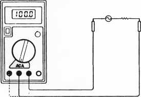
Fig. 5-4 AC Current measurement
Notę
1 If the current rangę is not known beforehand, set the FUNCTION switch to the highest rangę andwork down.
2 When only the figurę “1 ” is displayed overrange is being indicated and the FUNCTION switch must be set to at higher rangę.
3. The Maximum input current is 2A, or 20A depending on the jack used. Excessive current will blow the fuse which must be replaced.
The 20 A rangę is not protected by a fuse.
The fuse rating should not be over 2A This is to prevent damage to the internal circuitry
4. The Maximum terminal voltage drop is 200 mV.
1. Connect the BLACK test lead to the COM jack and the RED test lead to the V/Q jack (Notę: The polarity of the RED test lead is “ + ”)
2. Set the FUNCTION switch to the Q rangę to be used and connect the test leads across the resistance under measurement see Fig. 5-5.
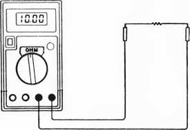
Fig. 5-5 Resistance measurement
Notę: 1. If the resistance value being measured exceeds the maximum value of the rangę selected, an over-range indication will be dispjayed (“1 ’’). Select a higher rangę. For resistance of approx-imately 1 Megohm and above, the Meter may take a few seconds to stabilize. This is normal for high resistance readings.
When the input is not connected, i.e. at open Circuit, the figurę ‘‘1 ” will be displayed for the overrange condition.
3 When checking in-circuit resistance, be surę the Circuit under test has all power removed and that all capacitors are fully discharged
4 The resistance ranges of this instrument are protected by a posister above 500V and a resistor network below 500V, except 200Q rangę (250V).
5 Some devices may be damaged by the current applied during resistance measurements. The following table lists the voltage and current available on each rangę
|
Rangę |
A |
B |
C |
|
200 Q |
0.65 |
0 08 |
0.44 |
|
2 K |
0.65 |
0.3 |
0.27 |
|
20 K |
0.65 |
0.42 |
0.06 |
|
200 K |
0.65 |
0.43 |
0.007 |
|
2 M |
0.65 |
0.43 |
0.001 |
|
20 M |
0.65 |
0 43 |
0.0001 |
A is open Circuit voltage at the jack B is voltage across a resistance equal to fuli scalę value
C is current m milliamperes thru a short eircuit at the input jacks All values are typical.
1. Connect the BLACK test lead to the COM jack and the RED test lead to the V/£> jack (Notę: The polarity of the RED test lead is “ + ”)
2. Set the FUNCTION switch to the -W- ranqe and connect the test leads across the diodę under measurement see Fig. 5-6
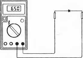
Fig . 5-6 Diodę measurement
Notę:
1. When the input is not connected, i.e. at open Circuit, the figurę “1” will be displayed for the overrange condition.
2. There is 1 milliamp Current flow through the device under test.
3. The meter displays the forward voltage drop in millivolts, and overload when the diodę is reversed.
1 Connect the BLACK test lead to the COM jack and the RED test lead to the V/Q jack 2. Set the FUNCTION switch to the f] rangę (same rangę) and connect the test leads across the resistance under measurementSee Fig. 5-7 3 Buzzer sounds if the resistance between two prods is less than approximately 30 ohms.
Notę:
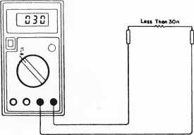
Fig. 5-7. Audible Continuity test
1 When the input is not connected, i.e. at open Circuit, the Figurę “1 ’ will be displayed for the overange condition.
2 The Circuit to be tested must be in power off status during the continuity check
1. Set the FUNCTION switch to the hFE rangę.
2. Determine whether the transistor is NPN or PNP and locate the Emitter, Base and Collector leads. Insert the leads into the proper holes in the Socket on the front panelSee Fig. 5-8.
3. The display will read the approximate hFE value at the test condition ot base current 10 \jlA VCE2.8V.
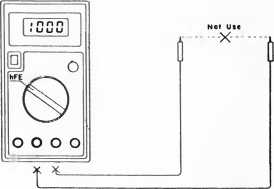
Fig. 5-8 Transistor hFE Test
6. MAINTENANCE
Your Digital Multimeter is a precision electronic device. Do not tamper with the circuitry To avoid damage:
A. Never connect morę than 1,000 Volts DC or 700 Volts RMS AC.
B. Never connect a source of voltage with Function Switch in OHM position.
C. Never operate the DVM unless the battery cover is in place and fully closed
D. Battery and/or fuse replacement should only be done after the test leads have been disconnected and POWER IS OFF.
6-1 9-Volt Battery Replacement
Notę the condition of the 9-volt battery using the procedurę described above If the battery needs to be replaced, open the Back cover, remove the spent battery and replace it with a battery of the same type.
6-2 Fuse Replacement
Should the fuse need replacement, use only 2-amp fuses identical in physical size to the original or use the spare fuse in the storage compartment adjacent to the main fuse in the Case (TopCover)
ro
O
>
o
JO
co
O
X
m
£
>
H
O
o
WARRANTY
Warrants this instrument to be free from defects in materiał and workmanship for a period of one year. Any instrument found defective within one year from the delivery datę and returned to the factory with transportation charges prepaid, will be repaired, adjusted, or replaced at no charge to the original purchaser. This warranty does not cover expen-dable items such as batteries or fuses. If the defect has been caused by a misuse or abnormal operating conditions, the repair will be billed at a nominał cost.
SECTION
1. INTRODUCTION ...................
2. FEATURES ...........................
3. SPECIFICATIONS ..................
4. GENERAL CHARACTERISTICS
5. OPERATION .........................
5-5 Resistance Measurements 5-6 Diodę Measurements 5-7 Audible Continuity Test 5-8 Transistor hFE Test
PRELIMINARY NOTĘ 5-1 DC Voltage Measurements 5-2 AC Voltage Measurements 5-3 DC Current Measurements
5- 4 AC Current Measurements
6. MAINTENANCE .....................
6- 1 Battery Replacement 6-2 Fuse Replacement
/WETEX - 3800
DIGITAL MULTIMETER
OPERATING MANUAŁ
Wyszukiwarka
Podobne podstrony:
80226 pg004 Introduction This book is a go do to tho principles of modellmg wilh fabnc for the aspir
Instructions to Authors This instruction is based upon Uniform Requirements for Manuscripts Submitte
j058 This image is hosted at mangafox.com. we take no credit for the creation or editing of this ima
r152 This image is hosted at mangafox.com. we take no credit for the creation or editing of this ima
i103 SxSKn-y 7°*(7)UAYUTASAMA This image is hosted at mangafox.com, we take no credit for the creati
i113 _<n(D V 1-% This image is hosted at mangafox.com. we take no credit for the creation or edit
i128 VII JUST HAV£ TO TRy HARP&RAli RIćHT This image is hosted at mangafox.com. we take no
Temporary Mobile Subscriber Identity (TMSI) This number is sometimes used instead of the IMSI. One r
więcej podobnych podstron