3
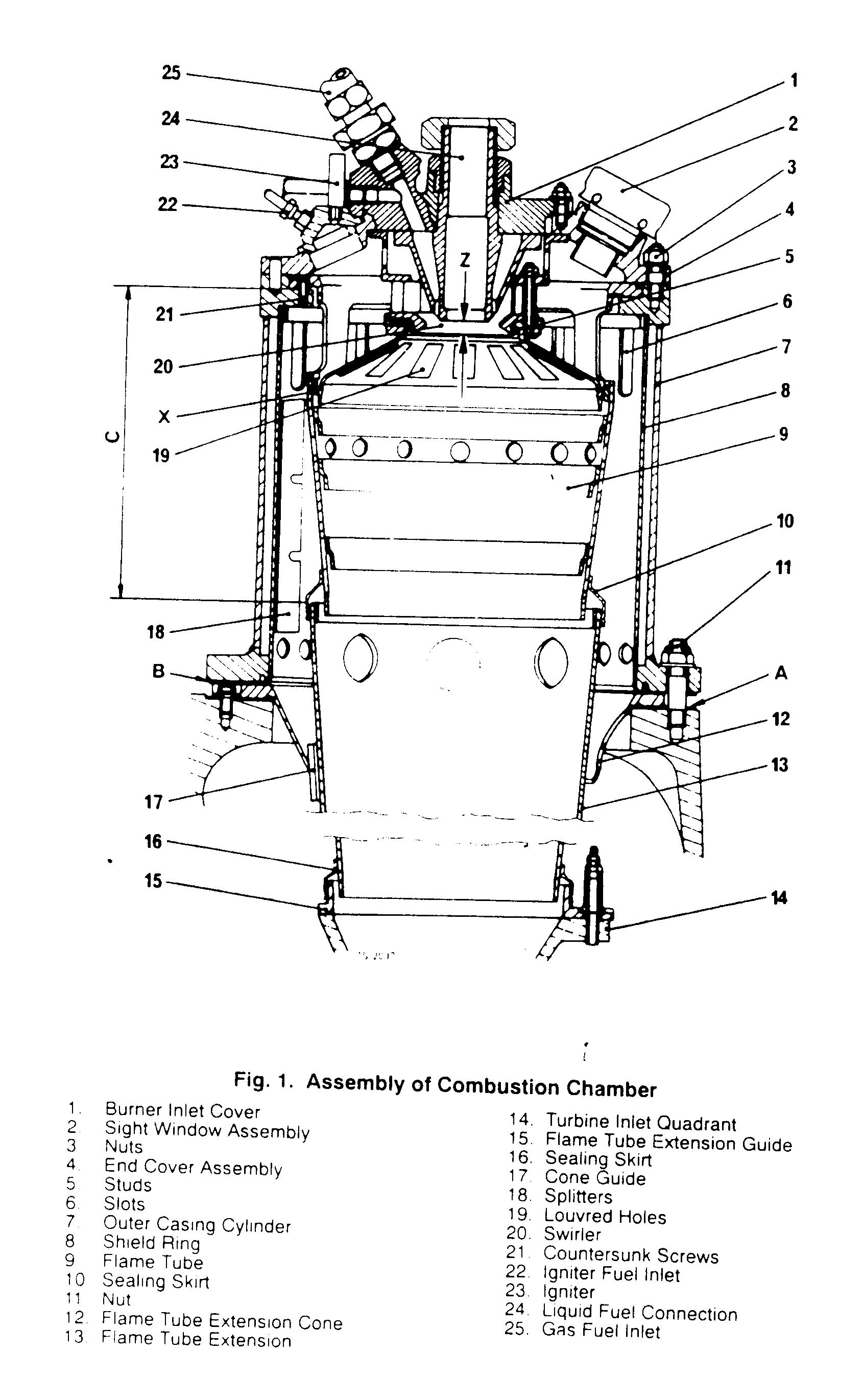
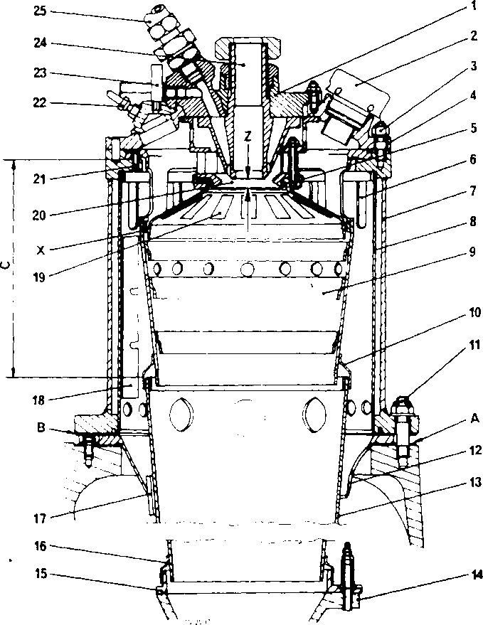
Fig. 1. Assembly of Combustion Chamber
|
1. |
Burner Inlet Cover |
14. |
Turbinę Inlet Ouadrant |
|
2 |
Sight Window Assembly |
15. |
Flame Tubę Extension Guide |
|
3 |
Nuts |
16. |
Sealing Skirt |
|
4 |
End Cover Assembly |
17 |
Cone Guide |
|
5 |
Studs |
18. |
Splitters |
|
6 |
Slots |
19. |
Louvred Holes |
|
7 |
Outer Casmg Cylinder |
20. |
Swirler |
|
8 |
Shield Ring |
21 |
Countersunk Screws |
|
9 |
Ramę Tubę |
22. |
Igniter Fuel Inlet |
|
10 |
Sealing Skirt |
23. |
Igniter |
|
11 |
Nut |
24. |
Liquid Fuel Connection |
|
12 |
Flame Tubę Extension Cone |
25. |
Gas Fuel Inlet |
13 Ramę Tubę Extension
Wyszukiwarka
Podobne podstrony:
siemens 1 Air-intake duet 2 Rib 3 Inlet casing 4 Burner 5 Combustion chamber 10 Tu
- 69 - I ju A 600-1 FIG. A - EFFECT OF THE SUPRESSOR ELECTRODE BIAS VOLTAGE ON TARGET ASSEMBLY CURRE
Slajd68 Bielactwo - kamuflaż Fig. 3.9.2 (a-d)Camouflaging of facia I vrtiligo in Iwo dark skinned pa
Image53 The sele of this book without ils cover is unauthorized. tf you purchased this book without
564 UN DfiBAT : LES MENTALITfiS COLLECTIYES 8 Fig. 2. Holders of publlc offices, men of busines
S5002321 260 MSeckć Żehrovicc in Bohemia Fig. 2. Interpretation of the ground plan ofbuilding 0/87-1
Fig. 3. Behavior of CO and C02 conceniration in the stack gases as a function of stoichiometric raii
199 RIKEN Accel. Próg. Rep. 24 (1990)V-2-34. Bending Fabrication of a Vaccum ChamberT. Nishodono, T.
Slajd68 Bielactwo - kamuflaż Fig. 3.9.2 (a-d)Camouflaging of facia I vrtiligo in Iwo dark skinned pa
16 TRIBOLOGIA 4-2003 Rys. 3. Widok nalepienia Al na powierzchni narzędzia Fig. 3. View of the a
28 Milena Napiórkowska Ryc. 4. Fragment Mapy geologicznej Polski 1: 200 000. Arkusz Płock. Fig. 4. P
więcej podobnych podstron