synare5 bmp

OSCILLATORS.
Testing. The output of the oscillators can be measured at the 4093, tuning pots, or the input to the fil ter. Common problems are broken switches, pots, and rarely, a bad 4093. (Notę that only RCA 4093s work well in this Circuit.) It is also normal for the triangle output to appear clipped until the filter's-0sc 2 pot is turned up.
FUTER.
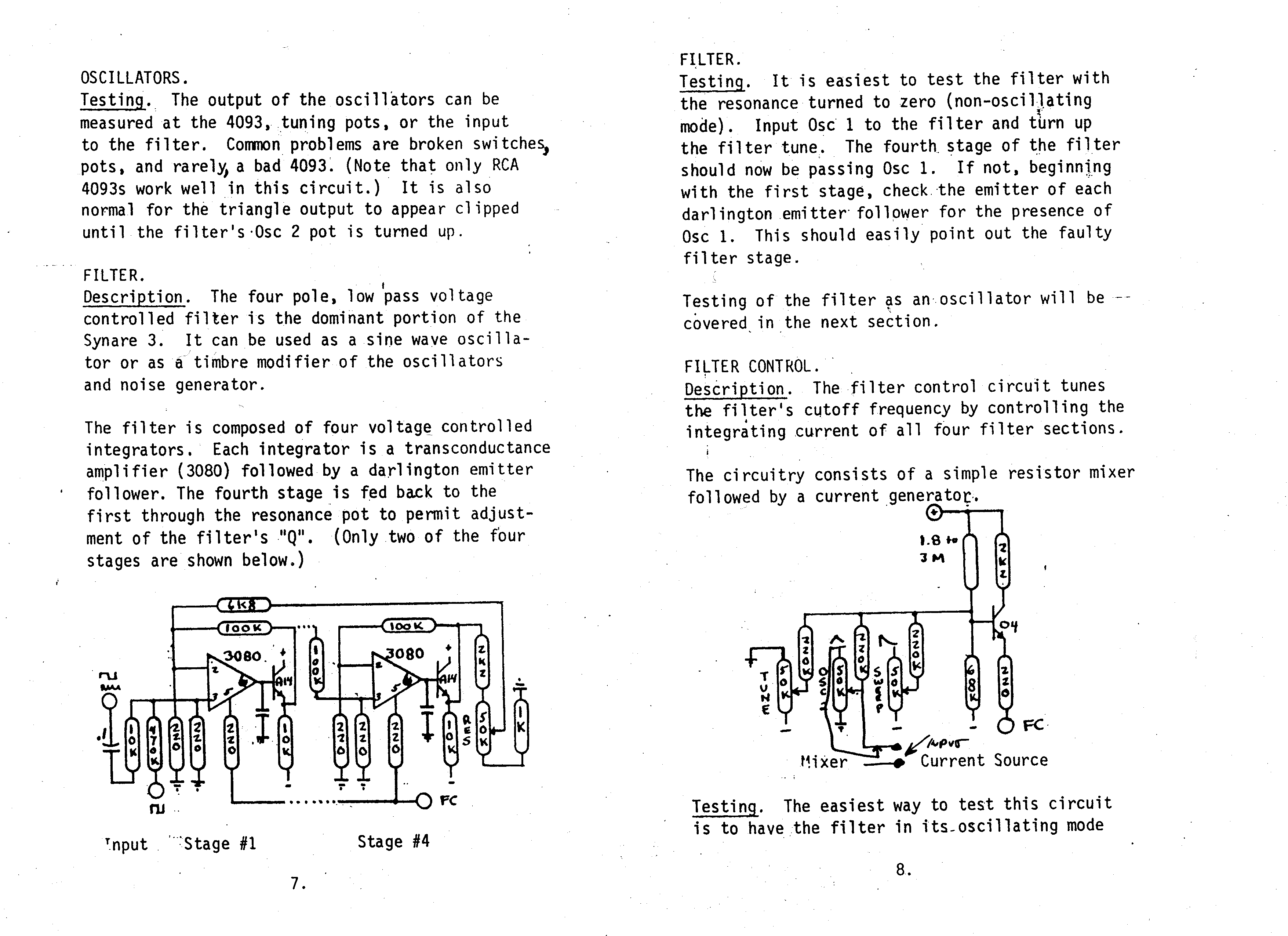
Description. The four pole, Iow pass voltage controlled filter is the dominant portion of the Synare 3. It can be used as a sine waye oscilla-tor or as a timbre modifier of the oscillators and noise generator.
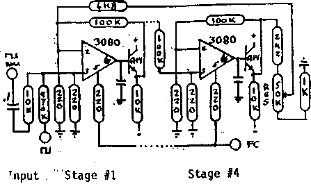
The filter is composed of four voltage controlled integrators. Each integrator is a transconductance amplifier (3080) followed by a darlington emitter follower. The fourth stage is fed back to the first through the resonance pot to permit adjust-ment of the filter's "Q". (Only two of the four stages are shown below.)

FILTER.
Testing. It is easiest to test the filter with the resonance turned to zero (non-oscillating modę). Input Osc 1 to the filter and turn up the filter tune. The fourth stage of the filter should now be passing Osc 1. If not, beginnlng with the first stage, check the emitter of each darlington emitter foliower for the presence of Osc 1. This should easily point out the faulty filter stage.
Testing of the filter ąs an oscillator will be --cóvered in the next section.
FILTER CONTROL.
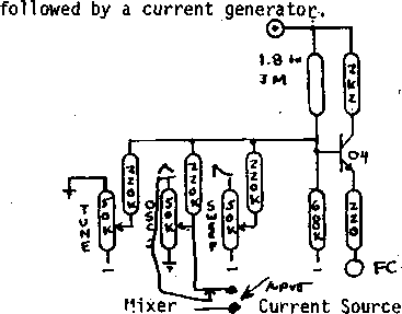
Description. The filter control Circuit tunes the filter's cutoff frequency by controlling the integrating current of all four filter sections.
The circuitry consists of a simple resistor mixer

Testing. The easiest way to test this Circuit is to have the filter in its-oscillating modę
8.
Wyszukiwarka
Podobne podstrony:
III. MODEL FORMULATION The output voltage of a single celi can be defined as the result of the follo
skanowanie0042 (10) the preparation of lesson plans can be very helpful. Especially, if this knowled
IMGS05 NOTES TO THE PLATES 1
47005 skanowanie0074 (3) 12.1.1.1. Sub-skills of listening Listening can be divide
skanowanie0074 (3) 12.1.1.1. Sub-skills of listening Listening can be divided into
Relay blok Błock Paramelers: Relay Relay Output the specified on or off value by comparing the
75 (31) Home SpaCellulite Becausejuniper promotes circulation and the dissolving of fat. it can be u
1.2. Goal and Plan of the Work 3 It is assumed that the goal of this work can be reached in the foll
another can be identified at the zonę of maximal plastic deformations. It is exactly in this zonę wh
IMGP3217 Fanconi anaemia In some cases the diagnosls of Fanconi anaemia may be snspected at birth, i
92 J. Ruchel, T. Adamczyk An example of basie computations can be computing an azimuth. The algo-rit
The division of sentences Sentences can be divided on the basis of: - Their functi
47005 skanowanie0074 (3) 12.1.1.1. Sub-skills of listening Listening can be divide
railway stations, where the service of stabling tracks can be use i railway stations, where rai
Convert6 Convert to Printed Circuit Board 3 Areas of solid copper can be added automatically to the
więcej podobnych podstron